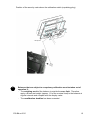
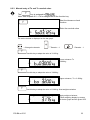
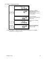
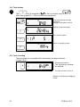
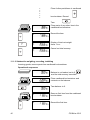
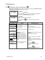
1
KERN & Sohn GmbH
Ziegelei 1
D-72336 Balingen
E-Mail: [email protected]
Tel: +49-[0]7433- 9933-0
Fax: +49-[0]7433-9933-149
Internet: www.kern-sohn.com
Operating instruction
Platform scale
KERN FIS
Version 1.2
07/2005
GB
FIS-BA-e-0512
GB
KERN FIS
Version 1.2 07/2005
Operating instruction
Platform scale
List of contents:
1
TECHNICAL DATA (VERIFIABLE) ..........................................................................................................4
2
DECLARATION OF CONFORMITY .........................................................................................................6
3
GENERAL .................................................................................................................................................9
3.1
3.2
3.3
3.4
4
CONSTRUCTION OF THE OPERATING INSTRUCTION:................................................................................9
WARRANTY .......................................................................................................................................10
SAFETY INFORMATION ........................................................................................................................11
IMPORTANT INFORMATION ..................................................................................................................11
INSTALLATION AND COMMISSIONING, OPERATING INSTRUCTIONS...........................................12
4.1
CONDITIONS APPLICABLE TO THE PLACE OF INSTALLATION ...................................................................12
4.2
INSTALLATION OF THE WEIGHING SYSTEM ............................................................................................12
4.3
FUNCTION TEST/READY-TO-OPERATE ..................................................................................................12
4.4
SCOPE OF DELIVERY ..........................................................................................................................13
4.5
LEVELLING THE WEIGHING SYSTEM .....................................................................................................13
4.6
MAINS CONNECTION ..........................................................................................................................13
4.7
POWER SUPPLY .................................................................................................................................13
4.7.1 Installation of the power supply by the customer .......................................................................13
5
CALIBRATION INFORMATION .............................................................................................................14
5.1
5.2
5.3
6
INFORMATION ON RECALIBRATION .......................................................................................................17
CALIBRATION INFORMATION FOR NON EU COUNTRIES ..........................................................................17
LEVELLING DEVICE .............................................................................................................................17
OVERALL VIEW OF THE EQUIPMENT.................................................................................................18
6.1
DISPLAY AND CONTROL PANEL............................................................................................................18
6.1.1 Display ........................................................................................................................................19
6.1.2 Keyboard.....................................................................................................................................19
6.1.3 General function keys .................................................................................................................20
6.1.4 Keys for weighing, recording and application functions .............................................................20
6.2
COMBINED FUNCTIONS .......................................................................................................................21
6.3
OPERATION AND CONTROL WHEN IN THE PARAMETER AND SERVICE MENU ............................................22
6.4
ALLOCATION OF THE FUNCTION KEY ....................................................................................................23
7
WEIGHING OPERATION........................................................................................................................25
7.1
FUNCTION TEST .................................................................................................................................25
7.2
WEIGHT DISPLAY ...............................................................................................................................26
7.3
ZERO SETTING...................................................................................................................................26
7.4
TARE FUNCTIONS...............................................................................................................................26
7.4.1 Net weighing with tare balancing................................................................................................26
7.4.2 Net weighing with fixed tare value ..............................................................................................27
7.5
GROSS WEIGHT, DISPLAY ...................................................................................................................27
7.6
TARE VALUE, DISPLAY ........................................................................................................................27
7.7
WEIGHT DISPLAY WITH INCREASED RESOLUTION (NON-VERIFIABLE) ......................................................28
7.8
UNIT SWITCH-OVER KG/LB OR LB/KG ...................................................................................................28
7.9
STORAGE VALUES AND OPERATING MODES .........................................................................................29
7.9.1 Fixed tare value ..........................................................................................................................29
2
FIS-BA-e-0512
8
TOLERANCE CHECK WEIGHING.........................................................................................................30
8.1
GENERAL ..........................................................................................................................................30
8.2
INPUT OF NOMINAL VALUE AND TOLERANCE LIMITS, FUNCTION START ....................................................31
8.2.1 Weighed nominal value and tolerances .....................................................................................31
8.2.2 Weighed nominal value, tolerance limits ± 2,5%, ± 5,0%, ± 7,5% .............................................32
8.2.3 Manual entry of Tu and To nominal value ..................................................................................33
8.3
OPERATING MODES, SETTINGS ...........................................................................................................34
9
COUNTING OPERATION .......................................................................................................................35
9.1
9.2
9.3
9.4
10
RECORDING (TOTALIZING)..................................................................................................................39
10.1
10.2
10.3
11
IMPORTANT NOTES CONCERNING PIECE COUNTING ..............................................................................35
START OF COUNTING PROCEDURE ......................................................................................................37
START OF COUNTING PROCEDURE WITH NUMBER OF REFERENCE PIECE RECOMMENDATION ...................38
CLOSING OF COUNTING PROCEDURE...................................................................................................38
ITEM RECORDING, ADDING ..................................................................................................................39
TOTAL DISPLAY ..................................................................................................................................40
TOTAL RECORDING ............................................................................................................................40
APPLICATION AND OPERATIONAL SEQUENCES ............................................................................41
11.1
WEIGHING, RECORDING, TOTALIZING...................................................................................................41
11.1.1
Additive weighing, recording, totalizing ..................................................................................41
11.1.2
Subtractive weighing, recording, totalizing.............................................................................42
11.2
COUNTING, RECORDING, TOTALIZING ..................................................................................................43
11.2.1
Additive weighing, counting, recording, totalizing ..................................................................43
12
PARAMETER AND SERVICE MENU.....................................................................................................45
12.1
SERVICE PASSWORD..........................................................................................................................45
12.2
GENERAL PARAMETERS .....................................................................................................................46
12.3
BALANCE PARAMETERS ......................................................................................................................47
12.3.1
QSF-Filter ...............................................................................................................................48
13
CALIBRATION (CAL) .............................................................................................................................49
13.1
13.2
13.3
14
GENERAL ..........................................................................................................................................49
CALIBRATION OF THE BALANCE BY SETTING THE “GEO“ VALUE .............................................................50
CALIBRATION OF THE BALANCE USING TEST WEIGHTS ..........................................................................52
MISCELLANEOUS..................................................................................................................................53
DISTURBANCES, CAUSES, REMEDIAL ACTION
...................................................................53
14.1
14.2
CLEANING .........................................................................................................................................55
14.2.1
Weighing terminal...................................................................................................................55
15
APPENDIX – BRIEF OPERATING INSTRUCTIONS.............................................................................56
16
ATTACHMENT (TERMINAL DIMENSIONS)..........................................................................................57
16.1
16.2
TABLE MODEL ....................................................................................................................................57
WALL MODEL .....................................................................................................................................58
FIS-BA-e-0512
3
1
Technical Data (verifiable)
Model
FIS 3K1 IPM
FIS 6K2 IPM
FIS 15K5 IPM
Readability (d)
1g
2g
5g
Weighing range (max.)
3 kg
6 kg
15 kg
Calibration value (e)
1g
2g
5g
Minimum load (min.)
20 g
40 g
100 g
Reproducibility
1g
2g
5g
±1g
±2g
±5g
0.1 g
0.2 g
0.5 g
3 kg (M1)
6 kg (M1)
15 kg (M1)
Linearity
Minimum single weight,
piece counting
Calibration weight (not added)
Net weight
12 kg
Weighing plate, stainless steel, width x
depth x height in mm
335 x 260
x ( min. 92 – max. 107)
Permissible ambient temperature
- 10° .... + 40° C
Max. air humidity
Display unit; width x depth x height in mm
Protective system
Mains supply depending on design (see
type plate)
Model
max. 80 % (non-condensing)
380 x 150 x 260
Terminal
IP68
Weighing system IP 67
without switch
either 230 V AC; +0.6%/-10%; 50 – 60 Hz
o or
120 V AC; +10%/-15%; 50 – 60 Hz
FIS 30K10 IPM
FIS 60K20 IPM
FIS 150K50 IPM
Readability (d)
10 g
20 g
50 g
Weighing range (max.)
30 kg
60 kg
150 kg
Calibration value (e)
10 g
20 g
50 g
Minimum load (min.)
200 g
400 g
1000 g
Reproducibility
10 g
20 g
50 g
± 10 g
± 20 g
± 50 g
1g
2g
5g
30 kg
60 kg
150 kg
Linearity
Minimum single weight,
piece counting
Calibration weight (not added)
Net weight
Weighing plate, stainless steel, width x
depth x height in mm
Permissible ambient temperature
Max. air humidity
Display unit; width x depth x height in mm
Protective system
Mains supply depending on design (see
type plate)
4
30,5 kg
500 x 400
x ( min. 86 – max. 101)
- 10° .... + 40° C
max. 80 % (non-condensing)
380 x 150 x 260
Terminal
IP68
Weighing system IP 67
without switch
either 230 V AC; +0.6%/-10%; 50 – 60 Hz
o or
120 V AC; +10%/-15%; 50 – 60 Hz
FIS-BA-e-0512
Technical Data (not verifiable)
Model
FIS 6K1 IP
FIS 12K2 IP
Readability (d)
1g
2g
Weighing range (max.)
6 kg
12 kg
Reproducibility
1g
2g
±2g
±4g
0.1 g
0.2 g
6 kg (M1)
12 kg (M1)
Linearity
Minimum single weight,
piece counting
Calibration weight (not added)
Net weight
12 kg
Weighing plate, stainless steel, width x
depth x height in mm
335 x 260
x ( min. 92 – max. 107)
Permissible ambient temperature
- 10° .... + 40° C
Max. air humidity
Display unit; width x depth x height in mm
Protective system
Mains supply depending on design (see
type plate)
Model
Readability (d)
Weighing range (max.)
Reproducibility
Linearity
Minimum single weight,
piece counting
Calibration weight (not added)
Net weight
Weighing plate, stainless steel, width x
depth x height in mm
Permissible ambient temperature
Max. air humidity
Display unit; width x depth x height in mm
Protective system
Mains supply depending on design (see
type plate)
FIS-BA-e-0512
max. 80 % (non-condensing)
380 x 150 x 260
Terminal
IP68
Weighing system IP 67
without switch
either 230 V AC; +0.6%/-10%; 50 – 60 Hz
o or
120 V AC; +10%/-15%; 50 – 60 Hz
FIS 30K5 IP
FIS 60K10 IP
FIS 120K20 IP
5g
10 g
20 g
30 kg
60 kg
120 kg
5g
10 g
20 g
± 10 g
± 20 g
± 40 g
1g
2g
5g
30 kg(M1)
60 kg(M1)
120 kg(M1)
30,5 kg
500 x 400
x ( min. 86 – max. 101)
- 10° .... + 40° C
max. 80 % (non-condensing)
380 x 150 x 260
Terminal
IP68
Weighing system IP 67
without switch
either 230 V AC; +0.6%/-10%; 50 – 60 Hz
o or
120 V AC; +10%/-15%; 50 – 60 Hz
5
2 Declaration of Conformity
KERN & Sohn GmbH
D-72322 Balingen-Frommern
Postfach 4052
E-Mail: [email protected]
Tel: 0049-[0]7433- 9933-0
Fax: 0049-[0]7433-9933-149
Internet: www.kern-sohn.de
Declaration of conformity for apparatus with CE mark
Konformitätserklärung für Geräte mit CE-Zeichen
Déclaration de conformité pour appareils portant la marque CE
Declaración de conformidad para aparatos con distintivo CE
Dichiarazione di conformità per apparecchi con contrassegno CE
English
Deutsch
Français
Español
Italiano
We hereby declare that the product to which this declaration refers conforms to the following
standards.
Please consider the chapter Calibration information in the user manual.
Wir erklären hiermit, dass das Produkt, auf das sich diese Erklärung bezieht, mit den nachstehenden
Normen übereinstimmt.
Unbedingt Kapitel Hinweise zur Eichung (Kap. 5 Eichhinweise) in der Bed.-Anleitung beachten.
Nous déclarons par la présente que le produit auquel se rapporte cette déclaration est conforme aux
normes citées ci-après.
Il est impératif de prendre en considération les indications concernant l´étalonnage (chap. 5
Remarques relatives à l'étalonnage) dans le manuel d´utilisation.
Manifestamos por medio de la presente que el producto al que se refiere esta declaración está de
acuerdo con las siguientes normas.
Le rogamos tener en consideración el capítulo "Indicaciones para la calibración" del presente manual
de instrucciones.
Dichiariamo con la presente che il prodotto al quale la dichiarazione si riferisce è conforme alle norme
di seguito citate.
Attenersi in ogni caso alle indicazioni relative alla taratura (Cap. 5 Istruzioni per la taratura) riportate
nelle Istruzioni per l’uso della bilancia.
Electronic Balance:
Mark applied
[year] 1) [code] M
1)
KERN FIS 3K1 IPM
KERN FIS 6K2 IPM
KERN FIS 15K5 IPM
EU Directive
KERN FIS 30K10 IPM
KERN FIS 60K20 IPM
KERN FIS 150K50 IPM
Standards
89/336/EEC EMC
EN 50082-1,2
73/23/EEC Low voltage EN 50081-1,2
EN 55011
90/384/EEC Non
EN45501:1992 1)
automatic weighing
Instruments 1)
Approval/Testcertificate N°
D02-09-001 1)
applies only to certified balances
gilt nur für geeichte Waagen
valable uniquement pour les balances étalonnées
sólo aplicable a balanzas verficadas
la dichiarazione vale solo per le bilance omologate
Date: 11.02.2004
Signature:
Gottl. KERN & Sohn GmbH
Management
Gottl. KERN & Sohn GmbH, Ziegelei 1, D-72336 Balingen, Tel. +49-07433/9933-0,Fax +49-074433/9933-149
6
FIS-BA-e-0512
KERN & Sohn GmbH
D-72322 Balingen-Frommern
Postfach 4052
E-Mail: [email protected]
Tel: 0049-[0]7433- 9933-0
Fax: 0049-[0]7433-9933-149
Internet: www.kern-sohn.de
Declaration of conformity for apparatus with CE mark
Konformitätserklärung für Geräte mit CE-Zeichen
Déclaration de conformité pour appareils portant la marque CE
Declaración de conformidad para aparatos con disitintivo CE
Dichiarazione di cofnromitá per apparecchi contrassegnati con la marcatura CE
English
Deutsch
Français
Español
Italiano
We hereby declare that the product to which this declaration refers conforms with the following
standards.
Please consider the chapter Calibration information in the user manual.
Wir erklären hiermit, daß das Produkt, auf das sich diese Erklärung bezieht, mit den nachstehenden
Normen übereinstimmt.
Unbedingt Kapitel Hinweise zur Eichung (Kap. 5 Eichhinweise) in der Bed.-Anleitung beachten.
Nous déclarons avec cela responsabilité que le produit, auquel se rapporte la présente déclaration,
est conforme aux normes citées ci-après.
Veuillez prendre en considération le chapitre Indication concernant l'étalonnage dans le mode
d'emploi.
Manifestamos en la presente que el producto al que se refiere esta declaración est´´a de acuerdo
con las normas siguientes
Le rogamos de considerar el capítulo Indicación para la calibración en el manual.
Dichiariamo con ciò che il prodotto al quale la presente dichiarazione si riferisce è conforme alle
norme di seguito citate.
In ogni caso rispettare gli indicazioni quanto riguarda l'omologazione nel manuale di uso della bilancia
Electronic Balance:
Mark applied
Date: 11.02.2004
KERN FIS 3K1 IP
KERN FIS 6K1 IP
KERN FIS 12K2 IP
EU Directive
89/336EEC EMC
KERN FIS 30K5 IP
KERN FIS 60K10 IP
KERN FIS 120K20 IP
Standards
EN 50081-1
EN 50082-1
EN 55022
Signature:
Gottl. KERN & Sohn GmbH
Management
Gottl. KERN & Sohn GmbH, Ziegelei 1, D-72336 Balingen, Tel. +49-07433/9933-0,Fax +49-074433/9933-149
FIS-BA-e-0512
7
Notice
Certified balances and balances used for legal applications have the EU type approval. The year of the initial verification is
shown next to the CE mark. Such balances are verified in the factory and carry the „M“ mark on the actual balance. The
year of initial verification is shown next to the CE mark. The GEO value of verified balances explains for which location of
use the balance has been verified. This GEO value is shown on the balance itself and on the packing. Further details see
GEO value table.
Hinweise
Für geeichte/eichpflichtige Waagen liegt eine EU Bauartzulassung vor. Das Jahr der ersten Eichung ist neben dem CE
Zeichen aufgeführt. Solche Waagen sind ab Werk geeicht und tragen die Kennzeichnung „M“ auf dem Gerät. Der GEOWert gibt bei vom Hersteller geeichten Waagen an, für welchen Aufstellungsort die Waage geeicht ist. Dieser GEO-Wert
befindet sich auf der Waage sowie der Verpackung. Genaueres ist der GEO-Wert-Tabelle zu entnehmen.
Remarques
Il existe une homologation UE pour les balances étalonnées/soumises à l´obligation d´étalonnage. L’année du premier
étalonnage est indiquée à côté de la marque CE. Ces balances sont vérifiées à la sortie d´usine et portent la marque „M“
sur l’appareil lui-même. Dans le cas des balances étalonnées par le fabricant, la valeur GEO indique le lieu d’utilisation
pour lequel la balance été étalonnée. Cette valeur GEO se trouve sur la balance ainsi que sur l’emballage. Vous trouverez
plus de détails dans le tableau de valeurs GEO.
Notas
Las balanzas verificadas/verificables cuentan con una aprobación de modelo UE. El año de la primera verificación está
indicado al lado del distintivo CE. Estas balanzas están verificadas en fábrica y llevan la designación „M“ sobre el propio
aparato. El valor GEO indica el lugar de ubicación por lo cual la balanza está verificado. El valor se encuentra sobre la
balanza así como sobre el embalaje. Por favor toman demás detalles de la tabla GEO.
Avvertenza
Per le bilance sottoposte/sottoponibili a verifica esiste un’approvazione CE del tipo. L’anno della verifica prima è riportato a
fianco del contrassegno CE. Queste bilance sono sottoposte a verifica in fabbrica e sono marcate con contrassegno ”M“. Il
valore GEO nelle bilance verificate in fabbrica indica il luogo d’impiego per il quale la bilancia è stata verificata. Questo
valore GEO è riportato sulla bilancia e sull’imballo. Ulteriori dettagli si possono ricavare dalla tabella “valori GEO”.
Tableau de valeurs GEO / GEO-value table
geographische
Breite/
geographicallatitude
0°
9°
15°
19°
22°
25°
28°
30°
33°
35°
37°
40°
42°
44°
46°
48°
51°
53°
55°
58°
60°
63°
66°
69°
73°
77°
8
0‘
52‘
6‘
2‘
22‘
21‘
6‘
41‘
9‘
31‘
50‘
5‘
19‘
32‘
45‘
58‘
13‘
31‘
52‘
17‘
49‘
30‘
24‘
35‘
16‘
52‘
-
9°
15°
19°
22°
25°
28°
30°
33°
35°
37°
40°
42°
44°
46°
48°
51°
53°
55°
58°
60°
63°
66°
69°
73°
77°
85°
Höhe über Meer in Metern /
height above sea level
52‘
6‘
2‘
22‘
21‘
6‘
41‘
9‘
31‘
50‘
5‘
19‘
32‘
45‘
58‘
13‘
31‘
52‘
17‘
49‘
30‘
24‘
35‘
16‘
52‘
45‘
0-650
650-1300
1300-1950
1950-2600
2600-3250
4/5
5/6
6/7
7/8
8/9
9 / 10
10 / 11
11 / 12
12 / 13
13 / 14
14 / 15
15 / 16
16 / 17
17 / 18
18 / 19
19 / 20
20 / 21
21 / 22
22 / 23
23 / 24
24 / 25
25 / 26
26 / 27
27 / 28
28 / 29
29 / 30
3/4
4/5
5/6
6/7
7/8
8/9
9 / 10
10 / 11
11 / 12
12 / 13
13 / 14
14 / 15
15 / 16
16 / 17
17 / 18
18 / 19
19 / 20
20 / 21
21 / 22
22 / 23
23 / 24
24 / 25
25 / 26
26 / 27
27 / 28
28 / 29
2/3
3/4
4/ 5
5/6
6/7
7/8
8/9
9 / 10
10 / 11
11 / 12
12 / 13
13 / 14
14 / 15
15 / 16
16 / 17
17 / 18
18 / 19
19 / 20
20 / 21
21 / 22
22 / 23
23 / 24
24 / 25
25 / 26
26 / 27
27 / 28
1/2
2/3
3/4
4/5
5/6
6/7
7/8
8/9
9 / 10
10 / 11
11 / 12
12 / 13
13 / 14
14 / 15
15 / 16
16 / 17
17 / 18
18 / 19
19 / 20
20 / 21
21 / 22
22 / 23
23 / 24
24 / 25
25 / 26
26 / 27
0/1
1/2
2/3
3/4
4/5
5/6
6/7
7/8
8/9
9 / 10
10 / 11
11 / 12
12 / 13
13 / 14
14 / 15
15 / 16
16 / 17
17 / 18
18 / 19
19 / 20
20 / 21
21 / 22
22 / 23
23 / 24
24 / 25
25 / 26
FIS-BA-e-0512
3 General
Please read the operating instructions carefully before working with your new
balance.
After unpacking, please check the equipment for any signs of external damage.
Keep all packaging in case it should be necessary to despatch the equipment. This
can help to prevent unnecessary damage.
Please go through carefully and observe the operating conditions in chapter 4
and the entire operating instructions before carrying out installation and
commissioning.
3.1
Construction of the operating instruction:
Explanation of symbols:
Information/reference to another explanation, limitation or
extension.
Important additional information for correct operation or
function of the equipment.
SAFETY INFORMATION ; please always observe!
Help, e.g. in cases of disturbances
Function sequence description:
Operation of Display content after operation of the
keys
keys
0
FIS-BA-e-0512
Description of the
function/process
Associated
process
9
3.2
Warranty
The weighing system is installed by staff members who have received training in
weighing techniques.
We cannot accept any liability for damage resulting from:
- non-observance of our operating conditions and operating instructions
- improper installation
- faulty electrical installation by the user
- modifications to our equipment
- removal of verification and protective marks
- improper operation
- improper handling of foil keyboard (for example, using sharp objects)
- natural wear and tear
- media/liquids which affect the following materials
Components
Material
Weighing terminal
Load carriers
Type WS . . . G sensors
Stainless steel 1.4301,
Stainless steel 1.4301
Stainless steel 1.4301, internal AlCuMg 2,
silicone caoutchouc diaphragms, polyethylene
cover
Housing seal
Frame: Polyamid
Seals:
Polyurethan
Keyboard foil
Polyester
Adjusting knobs for slope of Plastic, including brass nut and washer
equipment
(EPDM)
Mains line
PVC hose line, H05VV-F 3G0,75 incl.
integrally cast shockproof plug, 2.5 metres
long, or with plug for Switzerland or
USA/Canada.
Line screw fitting
Nickel-faced brass
Any claim to warranty is forfeited if faults/damages are caused due to intervention
by unauthorised persons, especially due to not using original KERN spare parts
or operating material.
All wear parts are excluded from warranty.
No warranty is offered for faults caused by the equipment being operated outside
its prescribed protective system. Damages caused due to environmental
influences such as sea water and unsuitable cleaning material are also excluded
from warranty.
10
FIS-BA-e-0512
When installing the equipment or changing equipment settings, always
carry out a test run with the known test weight at cyclic intervals. This avoids
incorrect results and evaluations.
Ensure that only trained personnel operate and take care of the equipment.
Please check that our products are handled appropriately.
Our products are regularly subjected to further development and are governed by
various regulations specific to the country. Illustrations and graphics used in the
operating instructions may differ from the model supplied.
3.3
Safety information
The equipment may only be opened by trained service engineers in compliance
with KERN directives.
Please disconnect the equipment from the mains before opening.
Warranty is forfeited if the equipment is opened.
The FIS weighing system may not be used in hazardous areas.
3.4
Important information
The measured values are stabilised by a short warm-up period lasting a few
minutes after switching on. Apply the items to be weighed carefully. Do not place
a permanent load on the weighing plate. Be sure to avoid knocks and
overloading in excess of the maximum load (max.), as this can cause damage to
the balance.
Switch the balance off for a short period of time following a disturbance in
programme sequence. The weighing process must now be repeated.
Check the balance regularly using external test weights.
Guarantee/warranty are forfeited if the balance is opened and following use
of the balance outside the prescribed directives.
Keep the packaging in case if should be necessary to return the equipment. Only
use the original packaging to return the equipment.
FIS-BA-e-0512
11
4 Installation and commissioning, operating instructions
4.1
Conditions applicable to the place of installation
-
Level installation surface
-
It must be ensured that the location is free from vibrations and that
installation is carried out in as dry an area as possible that is not subjected
to drafts.
-
Arrange the equipment in such a way as to facilitate operation, working
procedures and service.
-
As far as systems subjected to compulsory calibration are concerned, the
person weighing must have an unobstructed view from the evaluation
equipment to the place of weighing.
The weighing system is not suitable for the following environmental areas:
- Potentially explosive areas
-
4.2
Areas subjected to vibrations and jarring
External temperature ranges with temperatures below -10°C or
above +40°C
Installation of the weighing system
Unpack the weighing system carefully at the place of installation paying special
attention to the connecting cables.
Weighing belts or roller conveyor tracks may only be installed on the load carrier
after consulting with KERN.
Moving parts must not be able to re-charge.
Power-driven weighing belts or roller conveyor tracks must comply with the
requirements of the 98/37/EC directive on machinery.
4.3
Function test/ready-to-operate
An automatic function test is carried out as soon as the FIS is connected to the
mains supply.
The weighing terminal is operative when a weight value is displayed.
Maximum weighing accuracy is reached following a short warm-up period.
It is favourable to leave the weighing terminal connected to the mains voltage
for the entire working day.
A consistent operating temperature and highest possible balance accuracy are
achieved in this way.
Please be sure to observe chapter 13 on calibration (CAL).
12
FIS-BA-e-0512
4.4
Scope of delivery
The weighing system is supplied with the following components:
4.5
-
Load carriers
-
FIS weighing terminal
-
Operating instructions
Levelling the weighing system
The weighing system is levelled in the factory using the foot screws. Please
check that all 4 foot screws rest evenly on the supporting area.
The bubble level may also be installed underneath the load plate on small load
carriers.
Please compensate for any unevenness by adjusting the foot screws.
4.6
Mains connection
A separate mains switch is not available.
Maximum weighing accuracy is reached following a short warm-up period. It is
favourable to leave the weighing terminal connected to the mains voltage for
the entire working day.
A consistent operating temperature and highest possible balance accuracy are
achieved in this way.
4.7
Power supply
4.7.1 Installation of the power supply by the customer
Installation of the power supply for the connection of our equipment must be
carried out in compliance with the international standards and the regulations
deriving from these. They mainly include the recommendations of at least
one of the following commissions:
-
International Electrotechnical Commission
(IEC)
-
European Committee for Electrotechnical Standardisation
(CENELEC)
-
Association of German Electrical Engineers
(VDE)
Our equipment is designed according to VDE protection class III (protective low
voltage ).
FIS-BA-e-0512
13
5 Calibration Information
Weight symbol flashing:
Calibration switch (hardware seal) is not in secured condition.
Calibration switch (=equalising plug)
Traditionally, backup of the data relevant to calibration is carried out by means of
hardware backup (equalising plug on the circuit board in the terminal).
Equalising plug
Status
on the circuit board in the terminal
Plug not inserted
Plug inserted
Calibration data not saved
Calibration data saved
The calibration switch (equalising plug) can be seen through the right-hand window
on the terminal. This switch is secured by means of a sticker (stamp) when in
calibrated condition.
Balance calibration is not valid without the valid sticker.
The four screws on the rear side of the terminal must be opened in order to reach
the calibration switch (equalising plug).
Caution: Please remove the mains plug before opening the terminal.
The GEO value can only be changed or the balance calibrated if the calibration
switch (equalising plug) has been pulled out.
14
FIS-BA-e-0512
Position of the security mark above the calibration switch (equalising plug)
Security mark
Balances that are subject to compulsory calibration must be taken out of
operation if:
The weighing result of the balance is outside the error limit. Therefore,
apply a known test weight (approx. 1/3 of the nominal load) to the balance at
regular intervals and compare with the display value.
The recalibration deadline has been exceeded.
FIS-BA-e-0512
15
6
0,04
0,002
2002
20
M
1787281
1478071
Definition of the individual markings:
4591930100
=
Identification plate no.
KERN
=
Manufacturer
FIS
=
Type designation (basic type)
CE 2002
=
CE identification including the figures of the year in
which the CE identification was applied.
0103
=
Identification number of the named office “Calibration
Management Stuttgart“
D02-09-001
=
No. of the EU design approval
M
=
Square green sticker (metrology)
GEO 20
=
Calibrated for geo value area 20
=
Balance accuracy class III
Made in Germany
=
Manufacturing country
230V; 50/60 Hz
0.08 A
=
Electric data
IP 68
=
Protective system of the FIS terminal according to EN
60529.
6: Protection against dust contamination
8: Protection against water penetration
The weighing system is fitted with an IP 67 protective
system
A security mark is fitted in the evaluation equipment. In compliance with the
legal regulations, recalibration is to be arranged by the operator of the
balance.
16
FIS-BA-e-0512
5.1
Information on recalibration
A balance is recalibrated according to the legal requirements applicable to the
individual countries. For instance, the calibration validity period for balances in
Germany is normally 2 years. The period of time for calibration validity begins
when the balance is put into operation (installation and commissioning). Also see
the identification plate (2002 in the preceding example as designated CE 2002).
5.2
Calibration information for non EU countries
The statutory provisions of the relevant countries are to be observed.
5.3
Levelling device
The FIS is fitted with a bubble level. This must be checked following every
change in location and the balance re-levelled if necessary.
The bubble level may also be installed underneath the load plate on small load
carriers.
FIS-BA-e-0512
17
6 Overall view of the equipment
6.1
Display and control panel
Illuminated LCD display
Additional display for plusminus weighing
Minus weight LED red
Weight w. tolerance LED green
Plus weight LED yellow
Status display
Window for checking
protective mark
ON
OFF
0
T
Service functions
Basic weighing
functions
Standby/Test
Recording functions
Weight and
application values
18
Application functions
FIS-BA-e-0512
6.1.1 Display
1
1
2
1
= Status symbols:
: gross weight
NET
: net weight
battery voltage, battery depleted
recharge or change the battery
: recording procedure
: weighing application
: tolerance check
weighing application
: counting application
2
= weight, tare and application values including dimension
: multiple-range scale;
effective range = (1 or 2 or 3)
6.1.2 Keyboard
The balance is operated using fixed function keys.
For relevant applications, the function key
adjusted to individual operational procedures.
FIS-BA-e-0512
F
can be changed and
19
6.1.3 General function keys
ON
OFF
ON
OFF
Test (press key briefly)
2s
Actuation time: at least 2 seconds:
standby disconnection
Service functions
key is used for service purposes and is not
documented
6.1.4 Keys for weighing, recording and application functions
Tare
T
0
Cancel tare
Set to zero
Addition
F
20
Freely assignable function key
FIS-BA-e-0512
6.2
Combined functions
Additional functions can be activated within the function test phase (chapter 7.1)
after operating the
Selection
ON
OFF
(test) key for at least 2 seconds (2s):
Function/parameter group
User
group
“Test”
appears in
the display
ON
OFF
Operator
F
Chapter 6.4
2s
hold depressed for
2 seconds whilst
“test“ is seen on the
display
Assignment function key
F
“Test”
appears in
the display
ON
OFF
Selection of free parameter menu
0
Explanation
2s
Service
engineer
Chapter
7.9.1
8.3
hold depressed for
2 seconds whilst
“test“ is seen on the
display
FIS-BA-e-0512
21
6.3
Operation and control when in the parameter and service menu
Meaning of the function keys after selecting the parameter and service menu
Function
keys
F
T
Symbol
↓
Acceptance of the selected table value.
Relaying of selection or menu step
↑
Switch back selection or menu step
Prescribed value, relay to next decade, from left to right. The
decade of the highest value follows on again from the lowest
value. The activated decade is marked on the FIS by a line
segment.
0
22
Meaning/explanation
↓
Selection of the next table value/figure
↑
Selection of the preceding table value/figure
FIS-BA-e-0512
6.4
Allocation of the function key
ON
OFF
during “test” appears
F
2s
Selection of function key assignment
Selection
T
F
↑
↓
↑
Sub-selection
Symbol
0
display
Explanation
Counting function
-
↑
↓
Reference figure 5
-
↑
↓
Reference figure 10
-
↑
↓
Reference figure 15
-
↑
↓
Reference figure 20
-
↑
↓
Reference figure 25
-
↑
↓
Reference figure 50
-
↑
↓
Reference figure 100
-
↑
↓
Reference figure 200
-
↑
↓
Reference figure 250
↓
FIS-BA-e-0512
F
Plus-minus control
Determination of the
tolerance limits by
weighing
-
↑
↓
Percentage deviation of ±
2.5% of nominal value
-
↑
↓
Percentage deviation of ±
5% of nominal value
-
↑
↓
Percentage deviation of ±
7.5% of nominal value
23
Selection
T
F
Sub-selection
Symbol
0
display
Explanation
-
↑
↓
Nominal value and tolerance
limit entry using the cursor
keys (as nominal value
entry, chapter 8.2.3)
↑
↓
-
-
-
Fine resolution Weight
display with 10 times greater
resolution
↑
↓
-
-
-
Display of total
↑
↓
-
Call up fixed tare value
stores tare value
-
-
-
New weighing, tare value
↑
↓
-
-
-
Dimension switch-over
kg/lb and lb/kg
↑
↓
-
-
-
Tare value display
↑
↓
-
-
-
Gross weight display
After selection of the desired function and sub-selection, close assignment
function and save after operating the
ON
OFF
key.
The executable functions are described in chapters 7.5. to 10.2.
The factory setting for the
24
F
function key is marked with a ¿ .
FIS-BA-e-0512
7 Weighing operation
7.1
Function test
Automatic function test by
applying voltage or activating the
ON
OFF
ON
OFF
key (test).
All display segments and LEDs
are activated.
Display of the installed
programme version (example).
(6.459.51)
Version no. of approved software
Version no. functions
Amendment status
Changeover to weighing operation. The balance is now ready for operation
ON
OFF
Applying voltage or activating the
key after a stand-by disconnection
causes an automatic initial zero setting to be carried out if the weight value is
less than +/- 10% of the weighing range.
FIS-BA-e-0512
25
7.2
Weight display
The current weight is
displayed continuously.
7.3
Zero setting
0
7.4
Zero setting of weight
display; this function will be
executed when the weight
value lies within a range of
± 2% of the maximum capacity
range and when it has
stabilized.
Tare functions
The tare functions as described hereunder vary from country to country and are
subject to the applicable national Weights and Measures regulations.
A tare function is closed by means of the function key or by opening a new tare
function (sequential counterbalancing), i. e. only the last called up or weighed
tare value is active.
7.4.1 Net weighing with tare balancing
Counterbalancing with a
weighed tare value. This
function is executed when the
weight value lies within the
weighing range and has
stabilized.
26
FIS-BA-e-0512
7.4.2 Net weighing with fixed tare value
F
The
key is assigned to
and a fixed tare value stored.
Note: See chapters 6.2 – 6.4 for assignment of the function key
Counterbalancing by calling
up the fixed tare value.
A tare value of 5.48 kg has
been stored.
F
7.5
Gross weight, display
F
The
key is assigned to
.
Note: See chapters 6.2 – 6.4 for assignment of the function key
Gross weight display
F
Return to weighing mode
F
7.6
Tare value, display
F
The
key is assigned to
.
Note: See chapters 6.2 – 6.4 for assignment of the function key
Subtractive weighing
Tare value display
F
Return to weighing mode
F
FIS-BA-e-0512
27
7.7
Weight display with increased resolution (non-verifiable)
F
The
key is assigned to
, fine resolution.
Note: See chapters 6.2 – 6.4 for assignment of the function key
Selection of weight display
with increased resolution.
F
The resolution of the weight display is 10 times higher.
Return to normal weight display after activating the
5 second control period.
F
key or after expiry of the
Recording functions/addition are disabled in the 'weight display with
increased resolution' operating mode.
7.8
Unit switch-over kg/lb or lb/kg
F
The
key is assigned to
.
Note: See chapters 6.2 – 6.4 for assignment of the function key.
The total memory and a fixed tare value memory are available for each unit, i.e.
kg and lb.
Unit switch-over from kg to lb
F
Unit switch-over from lb to kg
F
Unit change-over is not possible if the tare or counting function is active.
28
FIS-BA-e-0512
7.9
Storage values and operating modes
7.9.1 Fixed tare value
A new fixed tare value can be stored by weighing if the
(chapter 6.4.).
FIS-BA-e-0512
F
key is assigned
29
8 Tolerance check weighing
8.1
General
In many weighing applications, it is not the absolute weight of an item that is of
interest, but the deviation of this weight from a nominal value. These
applications, for example, are weight control of packages of equal weight or the
process control of parts during a manufacturing process.
The FIS balance offers a variety of functions so as to ensure that these tests can
be carried out efficiently.
The results of this kind of tolerance check are displayed with the help of three
different display possibilities:
•
Pilot lamps (yellow-green-red)
The quickest information as to whether or not the item to be weighed lies within
the tolerance limits is supplied by the coloured pilot lamps located in the upper
section of the display housing. These pilot lamps are only in operation while the
tolerance check is active, otherwise they are not visible.
The pilot lamps provide the following information:
- item to be weighed within tolerance range
- green pilot lamp illuminated
- item to be weighed below lower tolerance limit - red pilot lamp illuminated
- item to be weighed above upper tolerance limit - yellow pilot lamp illuminated
•
Bar graph (display bar)
Further information is supplied by the bar graph in the upper section of the LC
display. This bar graph gives an analogue indication (by the length of the
presented bar) of where the weight of the item to be weighed lies within the
tolerance range. For this purpose, the tolerance range between the nominal
value and the upper or lower limiting value is always standardized in such a way
that it just corresponds to the length of the bar of the bar graph.
•
Weight value (numerical display)
The exact weight value is supplied by the numerical display which is also online during this operating mode. The following displays may be selected:
- display of the absolute weight value,
- display of the difference between the current weight value and the nominal
value (see chapter 8.3 operating modes, settings).
This type of display can be selected in “equipment settings“ (symbol display 9).
When delivered the standard equipment is set to absolute values display.
30
FIS-BA-e-0512
8.2
Input of nominal value and tolerance limits, function start
F
key is assigned to a tolerance check input function.
The
Input function selection is carried out as described in chapter 6.4.
8.2.1 Weighed nominal value and tolerances
F
The
key is assigned to
Note: See chapters 6.2 – 6.4 for assignment of the function key
A nominal weight of 2.000 kg is
on the balance
Start the tolerance check
function.
F
The nominal weight is weighed
on start-up of the function.
Weigh the lower Tu tolerance.
Apply a Tu weight of 1.800 kg
The weight value is indicated
The value for Tu has been
adopted.
F
Start weighing
Weigh the upper To tolerance
A To weight of 2.100 kg has
been applied
The value for To has been
adopted
F
Start weighing
The tolerance check is started after the To has been measured
The green pilot lamp indicates the result of the weight evaluation. Further weights can now
be checked. Nominal value and tolerance limits are maintained until the function is
switched off using the
FIS-BA-e-0512
F
key.
31
8.2.2 Weighed nominal value, tolerance limits ± 2,5%, ± 5,0%, ± 7,5%
F
2.5%, 5% or 7.5% are assigned to the
key
Note: See chapters 6.2 – 6.4 for assignment of the function key
A nominal weight of 1.700 kg is
on the balance
F
Start the tolerance check
function.
Setting, for example, ±5%
symmetrical to nominal value
The nominal weight is weighed upon start-up of the function.
Tu and To are calculated. The result is displayed on the bar graph and the signal LEDs.
Apply a new weight of 1.790 kg.
The weight is above To.
The yellow signal LED is
turned on.
32
FIS-BA-e-0512
8.2.3 Manual entry of Tu and To nominal value
F
key is assigned to
The
Note: See chapters 6.2 – 6.4 for assignment of the function key
Start the tolerance check
function.
F
Enter the nominal value
The active decade is displayed on the bar graph
0
→ Change the decade
F
↑ Decade + 1
↓ Decade - 1
Use this key to adopt the value of 3.125 kg
Lower tolerance Tu
3.000 kg
F
Use this key to adopt the value of 3.000 kg
Upper tolerance, To = 3.200kg
F
Use this key to adopt the value of 3.200 kg. Start weight evaluation
Apply weight to balance.
Check weighing display by means
of the bar graph and the green LED.
FIS-BA-e-0512
33
8.3
Operating modes, settings
Selection of service parameter
menu
ON
OFF
2s
if
“test“
appears
Selection of general
parameters
F
Selection
T
F
↑
↓
Sub-selection
Symbol
0
display
9
Explanation
-
↑
↓
0 +/- Operating mode
0 Weighing from zero, display of absolute
-
↑
↓
1 Weighing towards zero, display of
weight value
difference to the nominal value
↑
↓
10
-
-
↑
↑
↑
Automatic recording within the tolerance
range
↓
0 Excluding automatic recording within the
↓
tolerance range when the balance has
stabilized
1 Including automatic recording within the
tolerance range when the balance has
stabilized
↓
-
↑
↓
-
↑
↓
11
0 +/- LED operating mode
0 Signal LEDs are always active
1 Signal LEDs only active when the balance
12
has stabilised
↑
34
↓
-
↑
↓
0 Tare after addition
0 Off
-
↑
↓
1 On
FIS-BA-e-0512
9 Counting operation
F
key is assigned to
and a reference number, e.g.
The
pre-selected.
Note: See chapters 6.2 – 6.4 for assignment of the function key
9.1
,
Important notes concerning piece counting
Counting of pieces with the aid of a balance is based on a weight comparison
between the items to be counted and the base weight of an item, the so-called
reference weight.
The determination of the reference weight is decisive with regard to piece
counting accuracy. This is clearly shown by the following example.
Let us assume that one of the items to be counted weighs 1g.
This piece must be weighed in order to determine the piece weight. Let us also
assume that the weight of this piece is determined with an accuracy of 0.01g.
The relative accuracy, i. e. the relative error for this weight determination, is thus
0.01g divided by 1g, i. e. 1%.
If, for example, a large batch consisting of about a thousand pieces is to be
counted, this batch is weighed and the obtained weight value of this batch divided
by the reference weight, i. e. the weight of one piece.
The “n” number of pieces is thus derived from the division.
If the individual weight is determined within a margin of 1%, this error will be
transferred to the determination of the total number of pieces.
This means that when counting about 1000 pieces in this example, an error of ±
10 pieces is to be expected which, in turn, corresponds to 1% of 1000 pieces.
From this example it can be seen that the error (expressed in number of pieces)
during piece counting depends on the ratio of the number of pieces to be counted
to one piece (i.e. the reference piece).
In practice, a measuring error in the determination of the reference weight is
unavoidable. On the one hand, the accuracy of the balance is limited and on the
other, not all the pieces to be counted are of identical weight. They show a weight
tolerance which may easily fall within a percentage range.
If one happens to choose one of the lighter pieces as the reference piece, it is
obvious that the counting result will be different from the result which would be
obtained when choosing a reference piece with a weight in the upper section of
the dispersion range.
FIS-BA-e-0512
35
There are several ways of increasing the accuracy in piece counting.
• When determining the reference weight, use, for example, 10 rather than one
reference piece (weigh 10 pieces and divide the obtained weight value by 10).
-
This yields a number of advantages. The first is that the ratio between the
number of pieces to be counted and the number of reference pieces
reduces (figures from the above example), the ratio now being 1000/10 =
100 instead of 1000/1 = 1000 as before. Let us assume that the weight of
the 10 pieces has been determined with a balance error of 1%. This error
now only results in an uncertainty of ± 1 piece when counting
approximately 1000 pieces.
-
The second advantage of using several reference pieces is that the error
caused by the differing weights of the individual pieces is covered up by
the use of several pieces as reference size. In accordance with the rules
of mathematics, it is to be expected that this error is reduced by the factor
of the square root of the number of reference pieces, in this case by a
factor of approximately 3 (the square root of 10 is about 3).
When weighing reference pieces, external error sources should be eliminated as
far as possible. Such error sources might be:
- Wind pressure acting on the load plate as a result of air movements
- Vibrations and shocks
- Electrical disturbances
The first error source in particular may involve considerable errors when
determining the reference weight of very light parts.
When using several reference pieces, (particularly when these pieces are very
light), place them on the load plate together and not one by one.
The reason for this lies in certain equipment functions, which are normally not
noticed by the user and which serve to optimize the accuracy of the unit
(automatic zero plotting). These functions attempt to detect whether small weight
changes are ‘real’ changes or faults caused by vibrations, great temperature
changes or wind pressure.
If the reference pieces are very light and if the pieces are placed on the load plate
slowly one after another, the functions working in the background may interpret
the associated, small weight changes as interference and eliminate them.
36
FIS-BA-e-0512
9.2
Start of counting procedure
F
Calculation of reference
weight with the pre-selected
reference number.
Number of pieces = number of
reference pieces
Continuous display
Number of pieces according to
balance load
F
F
Change-over to weighing
mode
Return to counting mode
without new calculation of
reference weight
Note: See chapter 11 “Application and Operational Sequences“ for a detailed
description of counting procedure
FIS-BA-e-0512
37
9.3
Start of counting procedure with number of reference piece
recommendation
Reference weight mass too
small. Proposal: apply 3
additional reference pieces.
F
Apply 3 additional reference
pieces
Automatic calculation
Reference weight with
calculated number of
reference pieces
Continuous display
Number of pieces according to
the loading of balance
Even if a proposal is made to apply additional reference pieces, the counting
function can be started by activating the
9.4
key.
Closing of counting procedure
ON
OFF
38
F
Return to weighing mode
(counting procedure can be
re-started)
FIS-BA-e-0512
10 Recording (Totalizing)
Weighed items are stored in a memory to form totals.
∗ Total memory
• Net weight, tare weight, gross weight, (number of pieces)
• Item counter starting at 0 and item counter starting at 1
Note: See chapter 11 „“Application and Operational Sequences“ for detailed description of
recording.
10.1 Item recording, adding
− Recording procedure.
− The weight value is added to
the memory *kg.
− The consecutive number and
the item counter are increased.
FIS-BA-e-0512
39
10.2 Total display
F
The
key is assigned to
or call up function using
Note: See chapter 6.2 – 6.4 for function key assignment
2s
2s
Only active during counting
procedure:
Display of total piece number
Display of total net weight
F
Item counter display
F
Return to weighing mode
F
10.3 Total recording
Total recording is only possible after total display has been activated
(chapter 10.2).
− Recording procedure.
− The *kg memory contents
are deleted.
− The item counter is set to 0.
Return to counting or weighing
mode.
40
FIS-BA-e-0512
11 Application and operational sequences
The following sections give practical examples of weighing, counting and
operating sequences using recording and totalizing as well as the required
parameter settings
11.1 Weighing, recording, totalizing
Recording of individual and total weights.
Parameter settings
Assignment
F
Total display
11.1.1 Additive weighing, recording, totalizing
Outgoing goods: Pack parts in a cardboard box / container.
Operational sequences
Balance is not loaded, set to 0
and the total memory cancelled.
0
Place cardboard box/container on the
balance.
Tare balance to 0.
Place the first item parts in the
cardboard box/container.
Record the first item.
Apply any further packaging material
and tare balance to 0.
FIS-BA-e-0512
41
•
•
•
•
•
•
Place further parts/items in cardboard
box/container. Record
Tare
Place parts of any other item in the
cardboard box/container.
Record the item.
F
Display of total net weight
Items 1 to x.
Cancel out total memory.
11.1.2 Subtractive weighing, recording, totalizing
Incoming goods, remove parts from cardboard box/container.
Operational sequences
Balance is not loaded, set to 0,
and the total memory cancelled.
0
Place cardboard box/container and
contents on the balance.
Tare balance to 0.
Remove first item from the cardboard
box/container.
Record the first item.
42
FIS-BA-e-0512
•
•
•
•
•
•
Remove any further packaging
material and tare balance to 0.
Remove further parts/items from
cardboard box/container.
Record
Tare
Remove next (last) item from the
cardboard box/container.
Record the next (last) item.
Display of total net weight
items 1 to x.
F
Cancel out total memory.
11.2 Counting, recording, totalizing
Recording of individual weight/number of pieces and total weight/number of
pieces.
11.2.1 Additive weighing, counting, recording, totalizing
Parameter settings
Assignment
F
counting function with reference
number 10
Note: See chapter 6.2 – 6.4 for assignment of the
function key
Operational sequences
Balance is not loaded, set to 0
and total memory cancelled.
0
Place cardboard box/container on the
balance.
FIS-BA-e-0512
43
Tare balance to 0.
Place 10 reference parts in the
cardboard box/container.
Start counting with reference weight
calculation.
Number of pieces = reference figure.
F
Put the required number of the 1st item
into the cardboard box/container
Record the first item.
Balance is not loaded.
Place the empty cardboard
box/container on the balance if the
number of items does not equal 0,
then press
•
•
•
•
•
•
.
Processing/weighing of further items.
Place nominal number of pieces in
cardboard box/container, next item.
b
Display of total number of pieces
items 1 to x.
2s
Cancel out total memory.
44
FIS-BA-e-0512
12 Parameter and service menu
The service menu allows parameters to be set for a diversity of tasks and
requirements.
• Metrological functions
• Functions and applications
Functions are also made available for commissioning, tests and analyses.
The settable application and parameter functions are divided into 3 groups and
provided for the following user groups:
Function/parameter groups
Assignment of function key
F
User group
Operators
Free parameter menu
Customer technicians
Service parameter menu
Service technicians
/adjusting function
Verifiable balance parameters and adjustment data
This data can only be changed if the calibration jumper is plugged into the
relevant position (chapter 5).
All other parameters can be changed whenever necessary.
12.1 Service password
Access to the service parameter menu and balance adjustment is protected by a
password.
FIS-BA-e-0512
45
12.2 General parameters
Selection of the service
parameter menu.
ON
OFF
Selection of general
parameters.
when
“test“
appears
2s
F
Selectio
n
T
↑
F
Sub-selection
Symbol
0
display
↓
Explanation
01
-
↑
↑
↑
↓
↓
↓
-
↑
↓
-
09
8 Standard setting
0 +/- Operating mode
0 Weighing from zero, display of absolute
weight value
1 Weighing towards zero, display of difference
to nominal value
↑
↓
10
-
↑
↑
Automatic recording within the tolerance
range
↓
0 Without automatic recording within the
tolerance range at stabilization of balance
1 With automatic recording within the tolerance
range at stabilization of balance
-
↑
↓
-
↑
↓
0 +/- LED operating mode
0 Signal LEDs always active
-
↑
↓
1 Signal LEDs only active when balance has
↓
11
stabilized
↑
↑
↑
↑
↑
↑
↓
↓
↓
↓
↓
↓
12
-
↑
↓
-
↑
↓
→
→
→
→
→
↑
↑
↑
↑
↑
↓
↓
↓
↓
↓
34
40
41
42
43
0 Tare after recording
0 Off
1 On
25 Resting time
80 QSF digital filter
250
16
40
same as described in
section. 12.3
To close the general parameter menu with data storage in the EEPROM, press
ON
OFF
46
key.
FIS-BA-e-0512
12.3 Balance parameters
Selection of the service
parameter menu.
ON
OFF
2s
when
“test“
appears
0
PASS
Selection of the balance
parameters
Hidden input of the service
password.
Without the input of a
password, the parameters can
only be displayed but not
changed. Pass code is 0001.
The position is selected using
0
. The figure is entered
using
Adopt and check service
menu
F
Selection
T
F
↑
↓
↑
Sub-selection
Symbol
0
display
20
-
↑
↓
-
↑
↓
-
↑
↓
↓
FIS-BA-e-0512
31
Explanation
0 Verification flat
0 verified
1 non-verified
000 g-Factor, g/kg
Value pre-setting for decades
010 corresponds to 0.10 g/kg
Correction value according to GEO value
table (see chapter 13 Calibration)
47
↑
↑
↓
↓
34
-
↑
↓
→
↑
↓
→
↑
↓
40
25 Resting time for determination of stabilised
weight
Value pre-setting for decades
Value X 40 ms
OFF
0 QSF digital filter (see chap. 12.3.1)
80 Value presetting
↑
↓
→
→
↑
↑
↓
↓
41
↑
↓
-
↑
↑
↓
↓
42
↑
↓
→
→
↑
↑
↓
↓
43
Threshold value,
scale unloaded
ON
0 to 999
0 QSF digital filter (see chap. 12.3.1)
250 Value presetting
Threshold value, scale
0 to 999
loaded
0 QSF digital filter (see chap. 12.3.1)
16 4 / 8 / 16 / 32 / 64 Capacity of average value
memory
0 QSF digital filter (see chap. 12.3.1)
40 Value presetting
Creep factor
0 to 999
12.3.1 QSF-Filter
The default filter settings by the manufacturer are ideal for ordinary use. However, a
change of settings might be useful for special use. We recommend that such a change
of settings is carried out by specialist staff.
Steps - Setup Menu:
40 Lower threshold factor: Default value = 80
Permitted values: 1 - 999
Important parameter for (potential) balance equilibrium:
This parameter determines the lowest tolerance limit within which the computed incline
of the non-linearized curve must remain, in order to allow the corresponding nonlinearized value to be rated at a potential neutral position. The stated value gives the
percentage of a display digit. The higher the value, the greater is the tolerance of the
filter close to null position.
Settings - Rules of thumb:
As low as possible, as high as necessary. Values exceeding the default value are
usually only required in cases where a strong interfering signal occurs.
41 Upper threshold factor: Default value = 250
Parameter for (potential) balance equilibrium:
Permitted values: 1 - 999
This parameter determines the maximum tolerance limit within which the computed
incline of the non-linearized curve must remain, in order to allow the corresponding
non-linearized value to be rated at a potential neutral position. The stated value gives
the percentage of the lowest threshold factor. The higher the value, the greater is the
tolerance of the filter close to maximum load. The tolerance limit above the null
position and below the maximum load is interpolated between the lower and the upper
threshold factor.
Settings – rules of thumb:
As low as possible, as high as necessary. Values exceeding the default value are
usually only required in cases where a strong interfering signal occurs.
48
FIS-BA-e-0512
42 Main Filter Quantity:
Default value = 16 Permitted values: 4/8/16/32/64
This parameter determines how many of the most recent data values are maximally
included in the computation of the filter value in the case of a neutral position. The
higher the figure, the steadier is the filter value and the more robust it will also be
against single freak values. Values below the default value are mainly required for
apportioning applications or, if the small weight changes to be registered are very
minor. There are only very few occasions when values below 4 would be meaningful.
43 Slow action factor:
Default value = 40 Possible value: 1-999
Important parameter for balance equilibrium:
This parameter determines the tolerance limit within which the filtered non-linearized
curve must remain, in order to ensure a continuing neutral position for the balance.
The stated value gives the percentage of the lower as well as the upper threshold
factor. The higher this value, the greater is the filter's tolerance towards short
disturbances as well as slow weight changes.
Settings – rules of thumb:
As low as possible, as high as necessary. Values exceeding the default value are
usually only required in cases where a strong interfering signal occurs. If slow weight
changes are to be recognized, select small values.
13 Calibration (CAL)
13.1 General
When we weigh a material mass, we are attempting to determine its weight in a
weight unit. As the “g” acceleration of the fall and other factors vary from location to
location, the balance must be calibrated following every change in location, as
otherwise a 30 kg material mass would be displayed as such at one location and as
30.08 kg at another. This would be wrong, but can be prevented by placing a
correct material mass on the scale (let’s say 30 kg) and then informing the balance
that this is actually the amount that corresponds to 30 kg at that location and that
30 kg should thus be displayed – this is known as calibration.
A balance must be calibrated when first installed (if the balance has not already
been calibrated for the location), if it has been moved over a significant distance or
if required by the local regulations. This is necessary, because the weight of a
material mass at one location does not necessarily correspond to the value at
another location.
Please see chapter 5 “Calibration Information“.
FIS-BA-e-0512
49
13.2 Calibration of the balance by setting the “GEO“ value
The balance can be set to the local acceleration of the fall without using calibration
weights by applying the following GEO value table.
Caution: The GEO value information refers to brand new equipment.
If calibration has already been carried out using calibration
weights, the information in the GEO value table may no
longer be used.
Procedure when using the GEO values:
1) Read off the GEO value in the table:
geographische
Breite/geographical
latitude
0°
9°
15°
19°
22°
25°
28°
30°
33°
35°
37°
40°
42°
44°
46°
48°
51°
53°
55°
58°
60°
63°
66°
69°
73°
77°
50
0‘
52‘
6‘
2‘
22‘
21‘
6‘
41‘
9‘
31‘
50‘
5‘
19‘
32‘
45‘
58‘
13‘
31‘
52‘
17‘
49‘
30‘
24‘
35‘
16‘
52‘
-
9°
15°
19°
22°
25°
28°
30°
33°
35°
37°
40°
42°
44°
46°
48°
51°
53°
55°
58°
60°
63°
66°
69°
73°
77°
85°
52‘
6‘
2‘
22‘
21‘
6‘
41‘
9‘
31‘
50‘
5‘
19‘
32‘
45‘
58‘
13‘
31‘
52‘
17‘
49‘
30‘
24‘
35‘
16‘
52‘
45‘
Höhe über Meer in Metern / Height above sea
level in metres
0-650
4/5
5/6
6/7
7/8
8/9
9 / 10
10 / 11
11 / 12
12 / 13
13 / 14
14 / 15
15 / 16
16 / 17
17 / 18
18 / 19
19 / 20
20 / 21
21 / 22
22 / 23
23 / 24
24 / 25
25 / 26
26 / 27
27 / 28
28 / 29
29 / 30
650-1300
3/4
4/5
5/6
6/7
7/8
8/9
9 / 10
10 / 11
11 / 12
12 / 13
13 / 14
14 / 15
15 / 16
16 / 17
17 / 18
18 / 19
19 / 20
20 / 21
21 / 22
22 / 23
23 / 24
24 / 25
25 / 26
26 / 27
27 / 28
28 / 29
1300-1950
2/3
3/4
4/ 5
5/6
6/7
7/8
8/9
9 / 10
10 / 11
11 / 12
12 / 13
13 / 14
14 / 15
15 / 16
16 / 17
17 / 18
18 / 19
19 / 20
20 / 21
21 / 22
22 / 23
23 / 24
24 / 25
25 / 26
26 / 27
27 / 28
1950-2600
1/2
2/3
3/4
4/5
5/6
6/7
7/8
8/9
9 / 10
10 / 11
11 / 12
12 / 13
13 / 14
14 / 15
15 / 16
16 / 17
17 / 18
18 / 19
19 / 20
20 / 21
21 / 22
22 / 23
23 / 24
24 / 25
25 / 26
26 / 27
2600-3250
0/1
1/2
2/3
3/4
4/5
5/6
6/7
7/8
8/9
9 / 10
10 / 11
11 / 12
12 / 13
13 / 14
14 / 15
15 / 16
16 / 17
17 / 18
18 / 19
19 / 20
20 / 21
21 / 22
22 / 23
23 / 24
24 / 25
25 / 26
FIS-BA-e-0512
2) Read off the correction factor in the following table
GEO value
Kern & Sohn
0
1
2
3
4
5
6
7
8
9
10
11
12
13
14
15
16
17
18
19
20
21
22
23
24
25
26
27
28
29
30
31
Correction factor
(g/kg)
3.793196
3.588993
3.384772
3.180633
2.976372
2.772195
2.567998
2.363781
2.159648
1.955394
2.775476
1.547032
1.342822
1.138539
0.934448
0.730182
0.525999
0.321798
0.117577
-0.086559
-0.290817
-0.494991
-0.699183
-0.903394
-1.107623
-1.311768
-1.515932
-1.720215
-1.924415
-2.128532
-2.332768
-2.537021
3) Call up the scale parameter menu as described in chapter 12.3.
Then enter the correction value (ensure the digit sign is correct).
The positions are selected using
The figures are entered using
FIS-BA-e-0512
0
.
.
51
13.3 Calibration of the balance using test weights
Exercise particular care when carrying out the calibration procedure.
The GEO values are overwritten following calibration using test weights.
These may then no longer be used.
Selection of the service
parameter menu.
ON
OFF
2s
when
“test“
appears
PASS
Selection of balance
parameters.
Hidden entry of service password.
Programme start is
carried out if a pass word is
not entered.
Pass code is 0001. The
positions are selected using
0
F
F
F
0
.
0---
The figures are entered using
Dotted segments flashing
Adopt and check service
menu.
Balance completely installed
with load plate/pre-load and
stabilized
0 % max.
Zero calibration,
Zero calibration until the count
of the counter no longer
changes.
Apply max. load to the
balance
100 % max.
Range calibration,
Calibration of range until the
count of the counter no
longer changes.
F
Use
close/confirm
52
to
FIS-BA-e-0512
14 Miscellaneous
14.1
Disturbances, causes, remedial action
Continuous automatic check and test routines are carried out. Status and error
messages are the result of these test routines.
Soft Error
F
key. This permits operations to
Activate the
be continued on the weighing terminal
Hard Error
The error cannot be corrected.
Activating the
started
Disturbances
ON
OFF
key causes a function test to be
Causes
No power supply or plug
not connected
Pre-load missing or load
plate jamming.
Remedial Action
Connect the direct plug-in transformer
unit
Apply the pre-load.
Ensure that load plate has free play.
Weighing range exceeded. Unload the scale.
Vibrations at place of
installation
Material to be weighed in
contact with other parts
Weighing material unstable
Material to be weighed not
positioned properly on the
scale. In contact with other
parts.
Error in weighing terminal.
Error in load carrier
Eliminate disturbances at the place of
installation.
Adapt parameter settings.
Position the material to be weighed
properly.
Position it in such a manner as to
prevent it from coming into contact with
other parts.
ON
OFF
Activate the
key;
Inform KERN quoting the error
number.
ON
OFF
Activate the
key to remedy
momentary disturbances.
FIS-BA-e-0512
53
The most important error numbers
ADW error numbers
Err 20951
RAM error
Err 20952
ROM error
Err 20100
Weighing cell parameter too small for verifiable balances
(acknowledge using the tare cancel key)
Err 20101
Weighing cell zero point too small
Err 20102
Weighing cell zero point too large
Err 20800
Faulty data entered ( divided by zero )
Err 20851
ADW timeout, no ADW interrupt
Err 20900
Error on pre-load adaptation
EEPROM error numbers
Err 21049
Calibration attempt without EEPROM plug-in bridge
54
Err 21050
EEPROM writing error, e.g. calibration bridge not plugged in
Err 21051
Checksum error verifiable data RAM
Err 21052
Checksum error EEPROM block 1
Err 21053
Checksum error EEPROM block 2
Err 21054
Checksum error EEPROM block 3
Err 21055
Checksum error EEPROM block 4
Err 21056
Checksum error consecutive number
FIS-BA-e-0512
14.2 Cleaning
Pressure compensation
Pressure compensation
The weighing terminal has a pressure compensation device for the weighing cell.
This is located next to the measuring cable inlet and consists of a fixed connecting
piece with adhesive diaphragm and a screw plug.
There are three openings on the circumference of the fixed connecting piece and
these must not be clogged by dirt.
Depending on the degree of contamination, these openings must be cleaned at
certain intervals.
Unscrew the hexagonal screw plug and remove any dirt.
Be particularly careful not to damage the diaphragm.
Hand-tighten the screw plug after cleaning.
14.2.1 Weighing terminal
Clean the weighing terminal from time to time using a damp cloth.
Do not use aggressive cleaning agents.
Provide the unit with a water-tight cover when cleaning by means of a
pressure washer.
FIS-BA-e-0512
55
15 Appendix – Brief Operating Instructions
General Functions:
ON
OFF
ON
OFF
2s
Test
Activate for at least 2 seconds if
“test“ appears.
Standby disconnection
Weighing mode functions:
Zero setting
0
Tare
Cancel tare
T
Recording mode functions:
Record items +
Display total
ON
OFF
2s
Record total
ON
OFF
ON
OFF
2s
F
Selection
Function Key Assignment
F
Sub-selection
Symbol
F
0
display
↑
↓
-
↑
↓
↑
↓
-
↑
↓
↑
↓
-
↑
↓
Counting function, number of ref. pieces
5/10/15/20/25/50/100/200/250
Manual tolerance check
2.5: 5.0; 7.5;
Fine resolution display
↑
↓
-
↑
↓
Total display
↑
↓
-
↑
↓
↑
↓
-
↑
↓
Call up fixed tare value
New weighing of fixed tare value
Unit changeover
↑
↓
-
↑
↓
Display tare value
↑
↓
-
↑
↓
Display gross weight
T
56
2s
Explanation
FIS-BA-e-0512
16 Attachment (Terminal Dimensions)
16.1 Table model
Equipment
infinitely slewable
382
90
354
28
13
40
5
128
10
11
Instrument
leads
Pressure
compensation
Connecting line
18
Data line
Control line
140
200
Front view:
FIS-BA-e-0512
6
R1
338
57
16.2 Wall model
(100)
10
135
Equipment
infinitely slewable
18
40
60
Instrument
leads
Connecting line
28
Data line
90
382
Pressure
compensation
Contol line
125
Front view
58
6
R1
338
100
140
200
354
140
FIS-BA-e-0512