1
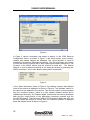
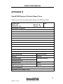
3500LR USER MANUAL 3500LR Receiver Series User Manual Issue 1.0, November Issue 1.0 11/04 3500LR USER MANUAL This page left intentionally blank Issue 1.0 11/04 3500LR USER MANUAL Notice to Customers This manual has been produced to ensure the very best performance from your OmniSTAR receiver. The manual has been clearly set out with simple instructions to ensure trouble free usage of your OmniSTAR receiver. This publication could contain technical inaccuracies or typographical errors. Changes are periodically made to the information herein; these changes will be incorporated in new editions of the manual. Should you require further assistance please contact your local dealer or the OmniSTAR Perth office. OmniSTAR Customer Support and 24 Hour Help Line OmniSTAR Pty Ltd 18 Prowse Street West Perth 6005 Western Australia Contact Numbers Office: Network Control Centre (NCC): Freecall – 24 hours: (08) 9322 5295 (08) 9321 0284 (24 hours) 1800 062 221 Fax Numbers Office: Network Control Centre: (08) 9322 4164 (08) 9321 0885 World Wide Web Internet Address: Email address: www.omnistar.com.au [email protected] i Issue 1.0 11/04 3500LR USER MANUAL Dealer Information Name _____________________________ Address _____________________________ City _____________________________ State _____________________________ Post Code _____________________________ Country _____________________________ Phone _____________________________ Fax _____________________________ Email _____________________________ ii Issue 1.0 11/04 3500LR USER MANUAL One-Year Limited Hardware Warranty OmniSTAR Pty Ltd and its operating companies world-wide (OmniSTAR), warrants this product to be free from defects in workmanship and material for a period of one year from the date of original sale by OmniSTAR or its authorised dealers, to the original purchaser or end user. OmniSTAR reserves the right to repair and/or replace, at its option, any part or parts found to be defective, provided such defects, in their opinion, are due to faulty material or workmanship and are not caused by unauthorised or improper repair or abuse, or normal wear. Purchaser shall be responsible for shipping and insurance of the returned product for repair under this warranty. OmniSTAR will pay shipping and insurance for the product's return to purchaser provided that the product returned proves to be defective under this limited warranty. This warranty applies only to normal usage of the product. It does not apply to units or electronic circuit boards defective due to improper installation or handling. Physical damage due to lightning or other electrical discharge and units subjected to fresh or salt-water contamination are not covered. OmniSTAR reserves the right not to warrant the product if, upon request, sufficient proof of recommended installation compliance as laid out in this manual is not provided. No other warranties are expressed or implied. No other warranties exist. OmniSTAR assumes no responsibility for any consequential or incidental losses or damages of any nature with respect to the use of this product. Issue 1.0 REVISION HISTORY November 2004 First Issue Manual Reference: 3500LR User Manual Copyright OmniSTAR Pty Ltd 2004. No part of this manual can be reproduced without the express permission of OmniSTAR Pty Ltd. iii Issue 1.0 11/04 3500LR USER MANUAL This page left intentionally blank iv Issue 1.0 11/04 3500LR USER MANUAL TABLE OF CONTENTS INTRODUCTION....................................................................................................1 ABOUT THIS MANUAL ...........................................................................................1 SYSTEM FEATURES..............................................................................................1 3500LR GETTING STARTED...............................................................................2 INITIAL SETUP ......................................................................................................2 MODES OF OPERATION SETUP ........................................................................5 MODEL 3500LR / RTCM MODE SETUP ................................................................5 MODEL 3500LR / VBS OR VRC MODE SETUP .....................................................6 RECEIVER INTERFACES ....................................................................................7 POWER ................................................................................................................7 ANTENNA .............................................................................................................8 DATA PORT A ......................................................................................................8 COMMAND PORT B ..............................................................................................8 INSTALLATION...................................................................................................10 INSTALLATION CONSIDERATIONS ........................................................................10 ELECTRICAL GROUNDING REQUIREMENTS .........................................................10 COUNTER ELECTROMAGNETIC FORCE (CEMF) .................................................11 CABLE INSTALLATION .........................................................................................12 ANTENNA LOCATION...........................................................................................13 TECHNICAL SPECIFICATIONS .........................................................................14 ACRONYMS USED IN THIS MANUAL ..............................................................15 APPENDIX A........................................................................................................17 CARE OF PORTABLE BATTERIES ........................................................................17 APPENDIX B........................................................................................................19 RECEIVER SERVICE PROCEDURE.......................................................................19 APPENDIX C .......................................................................................................21 OMNISTAR RECEIVER TOOLKIT ........................................................................21 APPENDIX D........................................................................................................31 OMNISTAR RECEIVER PROBLEM REPORT FORM ..............................................31 USER NOTES......................................................................................................32 v Issue 1.0 11/04 3500LR USER MANUAL INTRODUCTION About This Manual This manual has been produced to assist the typical user with the installation and operation of the 3500LR DGPS Receiver. System Features The 3500LR DGPS Receiver is a component part of the Fugro world-wide DGPS Service. The Fugro service is a full-time differential GPS (DGPS) broadcast system delivering corrections from an array of GPS reference stations located around the globe. Reference stations provide industry standard formatted corrections to Network Control Centres (NCC’s) at strategic geographic locations, where the corrections are decoded, checked, and repackaged in a highly efficient format for broadcast. The data is modulated onto a RF carrier that is then upconverted for transmission to an L-band communications satellite. The signals are received at the user's location by an antenna, demodulated by a receiver, and are made available, after selection of the desired individual reference site's data set, as corrections for use in a GPS, differential-capable, receiver. The 3500 series of receivers support the following OmniSTAR® services: 1. Virtual Base Station where the data from multiple reference stations is used in processor software to produce enhanced corrections for the user's location. The resulting corrections are restructured as RTCM SC-104 version 2 corrections for direct application to a user's receiver. 2. DGPS Services Stand alone differential GPS, where corrections from one selected site are extracted from the incoming data stream and are reformatted to an industry standard Format, RTCM SC-104. 3. Virtual Reference Cell, where the data from multiple reference stations is used in processor software to produce enhanced corrections for an optimised reference Cell. The resulting corrections are restructured as RTCM SC-104 version 2 corrections for direct application to a user's receiver or an internal Receiver. 1 Issue 1.0 11/04 3500LR USER MANUAL 3500LR GETTING STARTED The purpose of this section is to get you started with the 3500LR as quickly as possible. The guide will address receiving the satellite data carrier, and then checking the functionality of the external GPS engine if fitted. We would ask you to quickly review the menu section of this manual, the menus are navigated by the Arrow buttons on the front panel, changes to options are made with the Up/Down keys, and items are entered using the centre key. Generally when the receiver is supplied to you it will be configured for the mode and data link(s) you have subscribed to. In most cases to get up and running will be a case of connecting the appropriate cables and applying power to the system. Initial Setup Figure 1. Bare Rear View of 3500LR 1. Refer to the following diagrams as you will need to assemble all the required items. • • • • • • • 2. 3500LR DGPS Receiver DGPS Antenna DGPS Antenna Cable Power Cable Data Port Cable Power Supply External GPS Install the DGPS antenna where it has a clear view of the sky in the direction of the satellite, refer to the NCC in your region for an azimuth/elevation chart for the satellite service you have subscribed to. 2 Issue 1.0 11/04 3500LR USER MANUAL 3. Connect the DGPS antenna cable between the DGPS antenna and the 3500LR (TNC connector on rear panel). 4. Connect the power cable to a suitable 10-22V (10 – 36V if DC to DC converter fitted) DC power supply being sure to check correct polarity. 5. It is now time to make the 3500LR Receiver acquire the DGPS signal. This can be done by using Toolkit as explained in Appendix C. Toolkit will display regardless of whether the unit is receiving or not. 3 Issue 1.0 11/04 3500LR USER MANUAL This page left intentionally blank 4 Issue 1.0 11/04 3500LR USER MANUAL MODES OF OPERATION SETUP Set the receiver to the required mode (either RAW, RTCM, VRC or VBS). Some modes may not be available depending upon the security setting. Generally the receiver will be set to the correct mode prior to delivery to you, and will not be changeable. Model 3500LR / RTCM Mode Setup • If the 3500LR is operating in RTCM mode the RTCM data will appear on Port A. This port will need to be set up to match the requirements of your GPS receiver RTCM IN port. Toolkit can be used to set these. • Use Toolkit to set these. When using the 3500LR with an external GPS receiver only one RTCM station should be selected. An RS-232C data tester can be used to test for data output, the TX data line should flash every 3-4 seconds. DC Power Supply 3500LR Receiver DGPS Antenna Power Data Command/Data DGPS GPS Receiver Laptop Computer (Configuration & Maintenance) Figure 2. 3500LR Operating in RTCM Mode 5 Issue 1.0 11/04 3500LR USER MANUAL Model 3500LR / VBS or VRC Mode Setup In this mode a composite set of RTCM corrections is computed from the GPS network data sent over the link. The following information is required to compute these corrections; time (supplied via the link), GPS almanac data (supplied via the link), and receiver location either entered via Toolkit or from an external GPS receiver interfaced via Port A. When the unit is first supplied, or not used for a long period of time, or moved a large distance between use it may take up to 40 minutes to start outputting RTCM corrections. • If the 3500LR is operating in VBS/VRC mode the RTCM data will appear on Port A, this port will need to be set up to match the requirements of your GPS receiver RTCM IN/NMEA out port, use Toolkit to set these. • For the VBS or VRC operation the 3500LR needs to be supplied with a position for the area of operation, this can be supplied automatically from an external GPS receiver or manually via Toolkit. If using an external GPS input the GPS receiver must be set up to output $xxGGA NMEA format position telegrams in addition to any other required message types. The NMEA data is input via Port A, therefore the port parameters must match those set for the RTCM data output, see the set up details for this port above. 10 - 32V DC Power Supply 3500LR Receiver DGPS Antenna Power Port A Command/Data GPS Receiver DGPS Laptop Computer (Configuration & Maintenance) Figure 3. 3500LR operating in VBS or VRC Mode 6 Issue 1.0 11/04 3500LR USER MANUAL RECEIVER INTERFACES Power The 3500LR will operate on any DC Voltage between 10V and 32V DC. When operational, the unit dissipates 4W of power. The power input has reverse polarity protection. However, as the negative terminal is also attached to the housing ground, large currents can flow to any ground attachments made to the housing. Reverse polarity must therefore be avoided to prevent damage to the vehicle supply. At Voltages below 10V the unit will reset itself to prevent any data loss. At Voltages below 6V the receiver will turn itself off. Power is connected to the unit via a 2 metre long, black sheath, red & black 2-core cable. The cable is terminated with a 3-pin Switchcraft EN3C3F female connector. The connector pin layout is illustrated in Figure 5. Pin 3 Pin 1 Pin 2 Figure 4. Pin layout of Switchcraft EN3C3F Female Connector The Switchcraft EN3C3F connector is terminated as follows : Pin 1 + DC voltage (red) Pin 2 Not connected Pin 3 – DC voltage (black) 7 Issue 1.0 11/04 3500LR USER MANUAL Antenna Antenna connection is made via a 5 metre RG58 low loss cable, which is terminated with a standard TNC 50-ohm male connector. An antenna unit has an internal LNA (low noise amplifier) which is typically powered by 5V DC. When the 3500LR is powered up, this voltage is present at the antenna socket on the rear panel. Therefore, care must be taken not to connect or disconnect an antenna when power is on. Data Port A The Data port is a standard DB9 female socket. The External GPS plugs into this port. A laptop computer may be plugged into the Data port to migrate the RTCM output. Pin Number 1 2 3 4 5 6 7 8 9 Signal TXD2 RXD2 GND2 Table 1. Data Port Pin Assignment A special Data cable is supplied, terminated as shown in the Figure below. DB9 Male Pin number 2 3 5 2 metre cable ------------------------------------------- DB9 Female Pin number 2 3 5 Warning: Do NOT use standard RS232 cables. Command Port B The Command port is a standard DB9 female socket. Receiver configuration (OmniSTAR 3500LR board) can be carried out via this port by plugging in a laptop computer with ‘Toolkit’ software. 8 Issue 1.0 11/04 3500LR USER MANUAL The pin assignment for the Command Port B is shown in Table 2. Pin Number 1 2 3 4 5 6 7 8 9 Signal TXD1 RXD1 GND Table 2 Command Port Pin Assignment 9 Issue 1.0 11/04 3500LR USER MANUAL INSTALLATION Installation Considerations Before commencing installation of the 3500LR in a vehicle or aircraft, the following should be considered : • Determine the preferred location for each unit. Consider cable length, connector attachment space (cable bend radius), stowing excess cable, moisture, chemical corrosion, vibration and heat exposure. • Before drilling holes, consider using existing hardware and locations where equipment was previously installed. Avoid drilling holes that may damage other equipment (e.g. structural frame members, electrical cables or fluid lines). • High vibration and high temperature locations should be avoided whenever possible. • In application where vibration exceeds 4Gs acceleration, shock mounts are required. (Refer to Customer support for mounting recommendations). • Vehicle primary power has voltages that may be harmful to personnel and equipment. Disconnect the battery cable from the battery –ve (negative) terminal before making connection to any power terminal within the vehicle. Electrical Grounding Requirements The 3500LR requires a vehicle chassis connection that is a perfect ground. There should be a zero ohm reading between the receiver power socket –ve (negative) input and the point where the vehicle battery –ve (negative) terminal is connected to ground. 10 Issue 1.0 11/04 3500LR USER MANUAL Counter Electromagnetic Force (CEMF) A potential problem inherent in any installation of electronic systems within a vehicle is Counter Electro-magnetic Force (CEMF). CEMF is caused when relays or solenoids, connected to the vehicle DC power distribution, are de-energised. The voltage produced may exceed – 400 volts. CEMF is produced by equipment such as the following: • Electric fan brakes • Air conditioners • Starter relays • Electric pump relays CEMF is more than sufficient to damage or cause erratic operation of any electronic system that is also connected to the same vehicle DC power supply. CEMF can be eliminated by installing diodes at the relays and solenoids that cause the problem, and more importantly at the power supply cable connections on the receiver. A 47V, 5W, Zener diode (1N5368 or equivalent) should be connected between the receiver +ve (positive) power input terminal and ground, as illustrated in Figure 6. Battery +ve (positive) supply Ground Zener Diode Figure 6 Zener Diode Connected 11 Issue 1.0 11/04 3500LR USER MANUAL Cable Installation • Cables must be correctly installed for optimum system operation. Therefore, the following should be noted: • Do not route an L-Band receiver remote antenna cable with the cabling of any other radio system. This may cause interference between both systems. • If at all possible, do not run L-Band receiver antenna cables parallel to other radio system cabling closer than 30 centimetres. • If cables must cross, ensure that they cross at an angle of 90°. This minimises the possibility of interference. • As far as is practicable, ensure that cables and I/O connectors are unique and fit only in their allocated location. • Avoid routing cables along-side power generator cabling and other high electrical noise sources. This can cause interference. • Do not kink or force cables into sharp bends that may damage the cables and cause system failure. • After installation, ensure that excess cable in looped and clamped or tied safely away from any control cables, fuel lines, hydraulic lines or moving parts. When stowing over length cables, 150mm minimum cable bend radius. • Cable routing must (e.g. exhaust manifold). avoid form high loops not temperature less than exposure 12 Issue 1.0 11/04 3500LR USER MANUAL Antenna Location Antenna positioning is critical to system performance. The following conditions must be met for optimum system performance: • Antenna must be mounted at least 1.5 metres away from transmitting antennae of any frequency. Closer positioning may cause overloading of receiver RF circuits. • The antenna should be mounted at the highest practical point that will give a good view of the horizon and be as near level as possible. • The antenna must be located along the vehicle centre-line, or at a relevant reference point on the vehicle. 13 Issue 1.0 11/04 3500LR USER MANUAL TECHNICAL SPECIFICATIONS Receive Frequency 1525MHz to 1559MHz Environment Operating Temperature: Humidity: Vibration: Acceleration: 0° to 60°C 95% non-condensing 4G/60 Hz/x, y & z axes 4G Data inputs and outputs Two Serial Ports: Electrical Interference: Data Rates: Plug Types: Command and Data RS232-C 2400, 4800, 9600, 19200, 38400 DB9 Connectors RF Input to Receiver: Power Connector: TNC female Switchcraft En3C3F Power Power Supply: Power Consumption: 10V DC to 32V DC 340mA @ 12V Memory Program Memory: 2MB Physical Characteristics Dimensions (approx.): Weight (approx.): Display: Approvals Height 45mm Width 130mm Length 175mm 600 grams LED C-Tick 14 Issue 1.0 11/04 3500LR USER MANUAL ACRONYMS USED IN THIS MANUAL CEMF Counter Electro-magnetic Force DGPS Differential Global Positioning System GGA Global Positioning System fixed data (NMEA standard) GLL Geographic position (NMEA standard) GPS Global Positioning System GSA Global Positioning System, dilution of position, active satellite (NMEA standard) GSV GPS satellites in view (NMEA standard) LED Light Emitting Diode LNA Low Noise Amplifier NCC Network Control Centre NMEA National Marine Electronics Association (Standard for interfacing marine electronic devices) RF Radio Frequency RTCM Radio Technical Commission Maritime VTG ‘Track mode good’ and ‘ground speed’ (NMEA standard) ZDA Time and date (NMEA standard) 15 Issue 1.0 11/04 3500LR USER MANUAL This page left intentionally blank 16 Issue 1.0 11/04 3500LR USER MANUAL APPENDIX A Care of Portable Batteries General OmniSTAR supply a 12V portable battery pack to supply DC power for the receiver in the field. This is a ‘starved electrolyte battery’, which means that it is maintenance free. However, it is important to care for these batteries and to follow a strict charging regime in order to ensure a reliable DC power supply and long battery life. After all, the last thing you want in the field is a flat battery! Electrical Care of Batteries Starved electrolyte batteries do not like to be fully discharged; this can shorten their life. Therefore, it is important to put them on-charge regularly, keeping a log of charging and usage. It is recommended that an ‘intelligent’ charger be used. The intelligent charger will charge the battery normally until fully charged, then revert to a trickle charge. Do not put batteries on-charge using an ordinary charger that will keep on charging at the normal rate, even when the battery is fully charged. This can damage the battery and shorten its life. Physical Care of Batteries Batteries should be kept clean and dry. Dirt and moisture between the battery terminals can cause the charge to leak away, resulting in an unexpected flat battery when you switch on your equipment in the field. When transporting and installing batteries care should be taken to ensure that the terminals do not come into contact with such things as metal casings, vehicle chassis parts etc. Batteries should not be stored in an uncharged condition, as this will cause the internal parts to deteriorate. When a battery is to be stored, always charge it first. 17 Issue 1.0 11/04 3500LR USER MANUAL This page left intentionally blank 18 Issue 1.0 11/04 3500LR USER MANUAL APPENDIX B Receiver Service Procedure If an OmniSTAR receiver unit fails to perform, contact the Network Control Centre (NCC) within the region, after following the procedural checks. We wish to hear about frequently experienced problems and your assistance will help by copying the form on the next page, filling in the details requested and faxing or mailing the form to the NCC for on-forwarding to Product Marketing. The most common problems are interfacing, and usually occur at installation time. If you have an interfacing connection not covered in this manual we would like to assist you and produce another technical bulletin that may assist other users in the future. If a problem appears that you think may be caused by a system performance problem, contact the NCC in your region for any system aberrations that may have been experienced. We are sensitive to our customers’ needs and we want to assure specified system performance at all times. There could, however, be situations where conditions are below par, such as fringe area operations, radio communication disturbance etc., and, as OmniSTAR receiver monitors the system performance continuously, these conditions would be noted. 19 Issue 1.0 11/04 3500LR USER MANUAL This page left intentionally blank 20 Issue 1.0 11/04 3500LR USER MANUAL APPENDIX C OmniSTAR Receiver Toolkit 1. Opening Toolkit To run Toolkit, open the directory that contains Toolkit and double click on the file USERTK.EXE. 2. Running Toolkit for the First Time The first time that Toolkit is run, the communications port of your computer will need to be set up to correlate to the configuration of the command port of the receiver. A window, as shown in Figure 1, will appear and settings for the communications port of the computer will need to set up to attempt connection to the receiver. The settings are most commonly as follows: Port Name: Baud Rate: Parity: Flow Control: Stop Bits: Data Bits: COM1 57600, 38400, 9600 None None 1 8 Figure 1. When the settings have been entered, click OK. If the computer is communicating with the receiver correctly, Toolkit will display information about the receiver such as the serial number and the DGPS reception levels. The screen will look similar to Figure 2. 21 Issue 1.0 11/04 3500LR USER MANUAL Figure 2. In Figure 2 various information and status is display. In the ‘3500 Receiver Configuration’ frame, as shown in Figure 3, the serial number, group number, channel and manual stations are displayed. The ‘Serial Number’ is used for subscribing receivers for differential corrections. The ‘Group Number’ is the group to which the receiver belongs but is rarely used anymore and is default to 0. The ‘Channel’ is the DGPS service that the receiver is tuned into. The ‘Manual Stations’ is a list of reference stations to use when the receiver is generating the DGPS corrections. This is often blank meaning that it is automatic. Figure 3. In the ‘Static Information’ frame of Figure 2, the software versions and detector mode of the receiver is displayed, as shown in Figure 4. The ‘Software Version’ is the version of the software in the receiver. This version number is more important than the ‘Firmware Version’, which is a more general software version and is updated less commonly. The ‘Detector Mode’ controls how the receiver processes data and the output format of the differential corrections received over the OmniSTAR channel. This commonly VBS or RTCM, however RAW and VRC can be used. When the receiver is set for VRC, the reference position is displayed below the detector mode as shown in Figure 4. 22 Issue 1.0 11/04 3500LR USER MANUAL Figure 4. Displayed in the ‘Dynamic Information’ frame of Figure 2 is the reception status of the differential corrections, as shown in Figure 5. The ‘Actual Frequency’ shows the frequency that the receiver is currently tuned into followed by the symbol rate for the DGPS service. The ‘Signal Status’ displays whether the data received on that frequency is available. The ‘Service Identifier’ shows the tracking status of the receiver on the DGPS signal. The ‘Signal Quality’ displays the strength of the signal. Ideally this should be 8 dark bars. Figure 5. Shown in the ‘Subscription Information’ frame of Figure 2, as in Figure 6, are the details of the subscription of the receiver. The ‘Date & Time’ displays the current date and time that the receiver has decoded from the DGPS signal. The ‘Expiry Date & Time’ shows the time and date of which the differential corrections can no longer be used. The ‘Data Received’ shows what data that the receiver has decoded from the DGPS signal. For the receiver to operate correctly, i.e. produce corrections, ‘Time’, ‘Gps’, ‘Almanac’ and ‘Sites’ needs to be listed in this field. The ‘Subscription Status’ displays the state of your subscription and needs to say ‘Subscribed’ for correct operation. Figure 6. 23 Issue 1.0 11/04 3500LR USER MANUAL Lastly, in Figure 2, there are two buttons in the lower right. ‘Set Port’ displays a window that allows you to configure the port of your computer to communicate with your receiver. ‘Refresh’ simply refreshes the data on the screen in case of communication interruptions. These buttons are displayed in Figure 7 Figure 7. 3. Operation Menu The operation menu allows users to change various settings in the receiver. To access this menu click ‘Operation’ on the menu bar of Toolkit. A drop down menu will appear as shown in Figure 8. Figure 8. 3.1 Mode The mode of the receiver specifies the mode of operation of the receiver. To access this configuration click ‘Mode’ in the ‘Operation’ menu, as shown in Figure 9. A window will appear similar to that shown in Figure 10. Figure 9. Figure 10. 24 Issue 1.0 11/04 3500LR USER MANUAL This allows the user to select the 3500 Output Configuration and the port on which to operate. The default is VBS on the DATA port as shown in Figure 9. 3.2 Port Settings This item allows operators to configure the ports of the 3500 Receiver. To change the configuration of the ports, click ‘Operation’ menu, followed by ‘Port Settings’ and then the desired port to reconfigure being either Command or Data as shown in Figure 11. A window as shown in Figure 12 will appear. Figure 11. Figure 12. With the 3500, only the rate at which the port operates can be changed and not the parity, data bits or stop bits. Select the baud rate and click ‘OK’. 3.3 Channel Selection This menu item allows users to configure the channel on which to receive DGPS corrections. To adjust this setting, click ‘Operation’ menu followed by ‘Channel Selection’. Under ‘Channel Selection’ either select the service by entering the frequency, by clicking ‘By Frequency’, or by selecting the service, by clicking ‘By Service Name’. This is shown in Figure 13. Figure 13. 25 Issue 1.0 11/04 3500LR USER MANUAL ‘By Frequency’ If ‘By Frequency’ was clicked, a window will appear as shown in Figure 14. Figure 14. In this window, enter the frequency in Hertz and select a Symbol Rate. Click ‘OK’ to save and exit. ‘By Service Name’ If ‘By Service Name’ was selected, a window similar to that shown in Figure 15. Figure 15. Select the service to receive DGPS corrections from and click ‘OK’. 26 Issue 1.0 11/04 3500LR USER MANUAL 3.4 Glonass Sites Output To select the sites for Glonass output, click ‘Operation’ menu followed by ‘Glonass Sites Output’ as shown in Figure 16. Currently only ‘Auto’ can be selected, which will automatically select the nearest Glonass site. Figure 16. 3.5 Remote Sites Output To select the remote sites to use, click ‘Operation’ menu followed by ‘Remote Sites Output’. In here select ‘Auto’ to automatically select which remote sites to use in RTCM mode or select ‘Manual’. This is shown in Figure 17. Selecting ‘Manual’ will bring up the window as shown in Figure 18. Figure 17. Figure 18. Set the required sites in the list to use for DGPS corrections. Click ‘OK’ to save these settings. 4. Maintenance Menu The ‘Maintenance’ menu allows the download of firmware into the receiver and talk directly to the receiver. To open the ‘Maintenance’ menu click ‘Maintenance’ in the menu bar as shown in Figure 19. 27 Issue 1.0 11/04 3500LR USER MANUAL Figure 19. 4.1 Download New Software This item will allow users to download new firmware into the receiver. To access this, click ‘Maintenance’ menu followed by ‘Download New Software’, as shown in Figure 19. This will bring up a window similar to Figure 20. Figure 20. In this window locate the new firmware to download into the 3500 receiver. To do this, click ‘Select’, locate the file and click ‘Open’. Once selected, click ‘Download’. A window will appear asking for confirmation of this operation as shown in Figure 21. Figure 21. To continue, click ‘Yes’. At this point ensure that the power is not removed and that the data cable remains plugged in. After clicking ‘Yes’, a window similar to that of Figure 22 will appear and this shows the status of the download of the firmware. When the firmware has completed downloading, the button saying ‘Cancel’ will change to ‘Done’. Click ‘Done’. 28 Issue 1.0 11/04 3500LR USER MANUAL Figure 22. 4.2 Run Terminal To open the terminal click ‘Maintenance’ menu followed by ‘Run Terminal’, as shown in Figure 23. A window will appear as shown in Figure 24 that allows operators to send commands directly to the 3500. Figure 23. Figure 24. 5. Subscription Menu The subscription menu allows users to view the subscription details. To open this menu, click ‘Subscription’ on the menu bar. 5.1 Details To view the details of the subscription, click ‘Subscription’ menu followed by ‘Details’. This will bring up a window similar to that of Figure 25. This displays information such as the group number, expiry date, allowed modes of operation, enabled uplinks and range rings. 29 Issue 1.0 11/04 3500LR USER MANUAL Figure 25. 30 Issue 1.0 11/04 3500LR USER MANUAL APPENDIX D OmniSTAR Receiver Problem Report Form Please copy this form and report problem with as much detail as possible. Problem with: Signal Y/N OmniSTAR Y/N Date: Manual Y/N Receiver Y/N Description of problem: Person Reporting: Contact Phone #: Model #: Serial #: Customer Name: Customer Address: Customer Phone #: Date purchased: / GPS Receiver used: / Dealer: Serial #: Area of operations: Symptoms from display (if any): 31 Issue 1.0 11/04 3500LR USER MANUAL USER NOTES 32 Issue 1.0 11/04