1
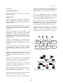
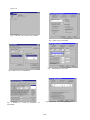
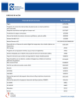
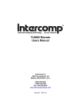
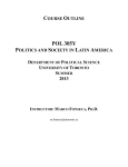
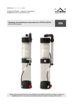
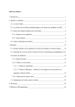
Proceedings World Geothermal Congress 2000
Kyushu - Tohoku, Japan, May 28 - June 10, 2000
THE BDGEO SOFTWARE PACKAGE: A MULTI-TOOLBOX SYSTEM FOR STORAGE,
VISUALIZATION AND ANALYSIS OF GEOTHERMAL DATA
Eduardo R. Iglesias, Rodolfo J. Torres, Rosa M. Barragán, Víctor M. Arellano, Yalú Galicia and Pedro R. Mendoza
Instituto de Investigaciones Eléctricas, Apartado Postal 1-475, 62001 Cuernavaca, Mor., México
Key Words: geothermal software, reservoir assessment,
databases, reservoir engineering, geochemistry.
specialist's computers, to save system's resources. Thus,
some users work only with the KERNEL, while others may
work with the KERNEL plus one or more toolboxes,
according to necessity.
ABSTRACT
There are four toolboxes (Fig. 1): (1) GEOQUIM
performs standard geothermal geochemical computations;
(2) an expert system called ANAPPRES that performs
automatic analysis of pressure well tests; (3) GEOSIM, a
numerical simulator of mass, energy and momentum flow
in geothermal wellbores; and (4) ANPROD, an expert
system for analysis of geothermal production data, aimed
at diagnosing well/reservoir performance (under
construction at the time of this writing, not described in
this paper).
BDGEO v4.0 is a user-friendly, integrated Windows
95/98/NT software package, set up as a distributed,
client-server application over a local area network. Its main
goal is to standardize and simplify the assessment and
management of geothermal fields at departmental level.
Extensive use of BDGEO by the technical staff of IIE's
Geothermal Unit demonstrated its main virtues: it saves
untold man-hours by automatically routing data between
different applications (databases, computing algorithms,
visualization tools); it keeps the Institution's geothermal
databases in one place and homogeneously updated; and
it dramatically improves the Institution's perception of its
data resources.
BDGEO v4.0 is written in Visual Basic (user interface,
communications with Control Module and databases) and
MATLAB (computations, visualization). The Access97
database management system is used for the Database
Module. Multiuser versions of MATLAB and Access97
are installed in the network server, for user's convenience.
In our standard setup the databases reside in the server,
though it is possible to install them in another network
drive. Depending on individually available hardware and
software resources, each user may choose to install
Access97 and/or MATLAB in his local drives or in a
network drive.
1. INTRODUCTION
Over the last few years we developed and tested the
BDGEO V4.0 software package, within the context of the
IEA's Geothermal Implementing Agreement, Annex IV,
Deep Geothermal Resources. Our main goal is to
standardize and simplify the assessment and management
of geothermal fields at the departmental level. This is
accomplished by providing all users with common
databases and standardized toolboxes for visualization and
analysis, that retrieve and format data transparently to the
user.
There is one Administrator of the System, with the usual
privileges, and a few Discipline Specialists with privileges
to update the databases. General Users cannot update the
databases. Different password levels, used for these
categories, are assigned by the Administrator. Access to
BDGEO is restricted by these
passwords.
2. ARCHITECTURE OF BDGEO V4.0
BDGEO's architecture is modular (Fig. 1). A Control
Module, accessible to all users, interacts with a number of
structurally identical databases, each belonging to a distinct
geothermal field, and with several Application Modules.
All Application Modules retrieve the necessary data from
the corresponding database, automatically and
transparently to the user.
2.1 The KERNEL
As mentioned, the KERNEL includes the Control Module,
the Database Module and the Visualization Module. These
modules are described in some detail in Iglesias et al
(1997). Due to space limitations here we describe them
briefly.
The main modules, collectively denominated KERNEL, are
the Control Module, the Database Module and the
Visualization Module. The KERNEL is installed in the
server and in all the networked computers and implements
the BDGEO v4.0 computing environment (Fig. 2). The
environment's user interface is in Spanish.
Control Module
Figure 3 presents the main screen of the Control Module.
The top menu reads (left to right) Applications,
Configure and Help. As shown, selecting Applications
presents options (top to bottom) Database, Visualization,
GeoQuim, Anappres, GeoSim and Exit. These options
correspond to the Application Modules and are displayed
Independent Application Modules, called toolboxes,
implement standard computations or tools for specialized
analysis. Toolboxes are meant to be installed mostly in
4043
Iglesias et al.
according to the toolboxes that have been installed in the
particular system running BDGEO.
Database Relationships presents a graphical depiction of
the tables, fields and relationships of the databases. This is
useful mostly to the database administrators.
Choosing Database allows (top to bottom) Select Active
Database, Access Active Database and Create New
Database. Selecting the top option displays a list of the
existing databases, to select from. The name and path of
the active database are shown in the bottom panel (H:\
Directorio de BDs\cprieto97.mdb, in this case). Data
manipulation and visualization is always performed on the
active database. Users may select another database
anytime. Selecting the bottom option allows one to
automatically create and name a new database, with our
standard structure, for another geothermal field. Selecting
the middle option opens the Database Access Module, as
described in the next subsection.
Visualization Module
BDGEO 4.0 offers visualization tools tailored for
assessment and management of geothermal fields. Figure
4 presents one of its main screens with the Specialized
Graphs option selected. Users navigate through layered
menus like this, selecting the type of graph and the data to
be visualized. Then, selection of the button Visualize
triggers the corresponding query to the active database
(transparent to the user) followed by screen visualization.
Graph parameters (colors, lines, symbols, scales, legends,
etc.) may be customized. When appropriate, users may
select curve fitting for their data. All graphs may be
printed.
The option Configure in the top menu allows users to: (a)
set default values for visualization parameters, such as line
(solid, dashed, etc.), symbol, color, legends, etc.; and (b)
to configure the drive:\path in which the databases,
MATLAB and Access97 are installed (see section 2).
Visualization is organized according to (see Fig. 4):
General Graphs (Gráficas generales) and Specialized
Graphs (Gráficas especializadas). General Graphs offers
the following types of graphs: variable vs. time, variable
vs. variable, Schoeller diagrams, triangular diagrams,
contours, profiles (variable vs. depth or elevation), and
lithological column.
Database Access Module
It offers the following functions: Forms, Reports,
Queries, Database Maintenance and Database
Relationships. Forms presents ad-hoc screens for
updating or consulting data. Only authorized users can
update data: a password is required. These screens are
designed for efficient manual uploading of data.
Furthermore, the screens resemble the paper data sheets
provided by the originating field/laboratory. Data that is
already in some form of computer file may be imported via
MS Access tools.
Specialized Graphs is organized into four disciplines.
These are (see Fig. 4, under Especialidades): Reservoir
Engineering (Ing. Yacimientos), Geochemistry
(Geoquímica), Geology (Geología) and Drilling
(Perforación).
Within Reservoir Engineering, three general types of
graphs are offered (Fig. 4, under "Areas de ING. DE
YACIMIENTOS"): Production (Producción), Output
Curves (Desarrollos) and Pressure Well Tests (Pruebas
de presión). In Production users can select (Fig. 4, under
"Tipo de Gráfica", top to bottom) Variable vs. Time,
Variable vs. Variable, Contours and Saturation Curves.
Saturation Curves are graphs of either log(pressure) or
log(temperature) vs. specific enthalpy, which incorporate
the bell-shaped saturation curves and lines of equal steam
quality. In Output Curves users can select to plot liquid
flowrate, steam flowrate, discharge flowrate, wellhead
pressure, and specific enthalpy of the discharge vs. each
other. In Well Tests users may plot: flowrate and pressure
vs. time, pressure vs. log[(t+∆t)/∆t], and p or ∆p vs. ∆t.
Reports offers three types of report: (i) for all the wells in
the active database, (ii) for one well, and (iii) for a date
interval in one well. Choosing one of these options opens
a dialog box to select one of the pre-defined standard
reports. Depending on the selected report, other dialog
boxes appear as necessary to choose relevant parameters
that define it. All reports may be printed, sent to an MS
Excel file for analysis or to MS Word for publication, via
standard MS Access tools.
Queries provides access to the standard queries created to
build the standard reports, and to other queries designed
and saved by users. Dialog boxes similar to those
described for the Reports function appear in the screen
when selecting Queries. Executing a query shows the
required data on screen.
Within Geochemistry one may chose to plot Variable vs.
Time, Variable vs. Variable, Contours, Triangular
diagrams based on anions or on cations, Schoeller
diagrams and FT vs. HSH (Gases grid) diagrams.
Variables include chemical concentrations in the liquid and
steam discharges, concentrations of stable isotopes,
temperatures, enthalpies, etc.
Database Maintenance: This function is only for database
administrators. A password is required to access it. It
provides the MS Access tools for modifying the
components of the databases and its relationships.
Within Geology users may opt to visualize Lithological
4044
Iglesias et al.
column, Distribution of minerals (%), Hydrothermal
alteration log, Texture log, and Homogeneization
temperature log. These graphs present variables vs. depth.
Users are allowed to select depth ranges for presentation.
In Distribution of minerals (%) users must chose mineral
types among Essentials, Accessories, Primary opaque,
Secondary transparent, and Neoformed. Each type is
presented in a separated graph. Users then have to select
which of the existing minerals in the chosen depth interval
to present in that graph. Logs of the selected existing
minerals are presented side by side for the chosen depth
interval (Fig. 5).
offered only the first two options just mentioned. Finally,
when selecting fed by "superheated steam", users are
presented five choices: TD (D'Amore and Panichi, 1980),
TCO2 (Arnorsson, 1985), TH2S (Arnorsson, 1985), TH2
(Arnorsson, 1985) and TFT (Fischer-Tropsch;
Arnorsson,1985). The results may be displayed in the
screen, saved to a file, printed in a report or plotted.
(iii) Provides a comprehensive set of
gas
geothermometers: D'Amore and Panichi's (1980) and five
gas geothermometers from Arnorsson and Gunlaugsson
(1985), TCO2, TH2S, TH2, TCO2/H2 and TH2S/H2.
Results may be displayed in the screen, saved to a file or
printed. They are presented by sample date and
geothermometer.
Within Drilling six types of graphs are offered. These are:
Lost circulation log, Lithology log, Well completion,
Temperature log, Pressure log and Heating rate log. In
Well completion one may select which of the recorded
completions (e.g., the original one, the one after the first
recompletion, etc.) to visualize. Heating rate logs are
automatically computed from sequences of temperature
logs obtained during the heating stage of the well. Users
must select which of the available logs to include in the
computations.
(iv) It is designed to compute a comprehensive set of
liquid phase geothermometers. The silica geothermometer
(Fournier and Potter, 1982); the Cationic Composition
Geothermoemeter (Nieva and Nieva, 1987); and four Na-K
geothermometers: Na/K (Truesdell, 1975), Na/K (Fournier,
1979), Na-K-Ca (Fournier and Truesdell, 1973) and Na-KCa corrected by Mg (Fournier and Potter, 1979). Results
may be presented in the screen, saved to a file, printed or
plotted.
2.2 The GEOQUIM toolbox
2.3 The ANAPPRES toolbox
This toolbox is described in some detail in Iglesias et al
(1998). Due to space limitations here we describe it
briefly.
This is an intelligent system for automatic analysis of
pressure well test. Interference tests with any number of
observation, active and dual wells with variable flowrates
can be analyzed, as well as drawdown tests with variable
flowrates. Previous versions of ANAPPRES
were
presented by Arellano et al. (1990a, 1990b, 1989).
GEOQUIM performs four types of standard geochemical
computations: (i) equilibrium distribution of species in the
reservoir; (ii) Cl- concentration in total discharge and in
reservoir liquid; (iii) gas geothermometers; and (iv) liquid
phase geothemometers.
Figure 4 presents ANAPPRES main screen. The active
database is shown in the upper left window (cprieto97.mdb
in this case). All the pressure test logs in the active
database are automatically presented, either in the list of
observation wells (left) or in that of the active wells (right).
These show, from left to right, a column for selecting logs,
the name of the well and the log's identifier. Dual logs,
those with both pressure and flowrate records, are shown
in both lists. The range of dates covered by the selected
logs (those marked with an "X") is shown in two small
windows below that displaying the active database.
Changing the range of dates narrows, widens or displaces
in time the lists of active and observation logs, to facilitate
selection. Under each list is a button that presents detailed
information about the selected well/log . Here users may
review the corresponding data list or plot it (pressing the
button under the list).
(i) These computations are based on EQQYAC (Barragán
and Nieva, 1989), a program that calculates the
equilibrium distribution of inorganic aqueous ion species
in geothermal reservoirs from the chemical composition of
discharged fluids and in situ physical measurements. The
required reservoir temperature is automatically computed
from the composition of the discharge, by means of a
liquid phase geothermometer. For greater flexibility, we
plan to add an option to assign a reservoir temperature,
bypassing the geothermometer calculation.
(ii) One may select to compute the Cl- concentration in
total discharge and/or in the reservoir. Users are asked
whether the well is fed by liquid, liquid and steam or
superheated steam. Then they are presented with choices
of relevant geothermometers to compute deep
temperatures, depending on how the well is fed. Selecting
"liquid" elicits three options: Cationic Composition
Geothermometer (Nieva and Nieva, 1987), Na-K-Ca
(Fournier and Truesdell, 1973) or silica (Fournier and
Potter, 1982). If fed by "liquid and steam" users are
Clicking the button in the lower right of the main screen
runs the expert system. First the system searches for
interference between wells and computes the
corresponding values of transmissivity and storativity, by
4045
Iglesias et al.
fitting a model to the data with a given tolerance for a χ2
statistic. Then it finds the boundaries, if any (Fig. 5).
Finally, the system determines the boundary types (closed,
constant pressure) and their locations, if there are enough
data. By default, the results are presented in tables with
comments (Fig. 5). Each card in the screen of Fig. 5
corresponds to one of the three stages of the analysis just
mentioned. One can also automatically generate a standard
report in MS Word, clicking the option Informe (Fig.
5).The relative locations of the wells, with or without lines
between wells indicating interference may be plotted,
clicking the buttons Graf. de interferencia and Graf.
ubicación pozos, respectively. Clicking on Graf. de
comparación brings about a figure comparing the
measured and computed pressures versus time.
pressure, liquid and steam flowrates and wellhead enthalpy
are automatically shown in the table inmediatly below
these windows. Below the table, the Input data (Datos de
entrada) box shows data at inlet (top to bottom): mass
flowrate, pressure, temperature, steam/water ratio and
enthalpy. The boxes marked "Temperatura" (Temperature)
and Presión (Pressure) are used when selecting output
curves or well logs for input.
The Description of piping (Descripción de tuberías, Fig. 8)
card also allows data input either manually or
automatically from the selected database. Manual input
overrides automatic input. From left to right the variables
on the table are: flow path length at beginning of segment,
tubing ID, casing ID, tubing wall thickness, overall heat
transfer coefficient, inclination of segment from vertical,
type of flow (0=tubing, 1=annulus), rock temperature at
HTCH.
2.4 The GEOSIM toolbox
This is a gheothermal wellbore flow numerical simulator.
The mathematical model is based on Gould's (1981)
VSTEAM program.
The Well and flow conditions (Condiciones del pozo y
flujo) card (not shown) allows selection of the following
parameters/choices: number of wellbore geometry
segments, number of radial blocks in the reservoir, flow
direction (up or down), compute pressure from top to
bottom or viceversa, include the kinetic energy term in the
calculations, use slip/non-slip density. Users must indicate
whether to compute pressure/quality profiles or well
deliverability. Three types of heat transfer may be selected:
Ramey's (analytic), Willhite's annular or transient. There
are also the following selections for vertical two-phase
correlations: Hgedorn and Brown, Orkiszewski, Aziz and
Govier, Beggs and Brill and Mukeherjee and Brill.
Figure 6 presents GEOSIM's main screen. The menu bar
offers, from left to right: Run, Reports, Exit and Help. The
Reports option allows user to open and edit preformatted
reports that GEOSIM generates automatically in MS Word.
The remaining options are self-explanatory.
The lower left button allows selection of the active
database. The path to the selected database is shown in the
lower middle window (H:\Directorio de Bds\chipila97.mdb
in this case). The middle button (Terminar) exits the
toolbox. The right button (Ejecutar >>) runs the
simulator.
The Case conditions (Condiciones del caso) card (not
shown) inputs the following parameters: flow length, rock
temperature at surface, rock temperature at bottom, pipe
roughness, heat transfer coefficient from fluid to outer
cement, diameter of outside cement, flowing time for heat
transfer, reservoir heat transfer coefficient, thermal
diffusivity and exterior radius for reservoir calculations.
As shown in Fig. 6, there are six "cards" in this screen.
They are used to input the necessary data and choose
several computational options. In the first card, Initial
options (Opciones iniciales), users may write a case
description, comments, etc., that will be automatically
incorporated in the report, in the upper left window. They
can also choose whether to include the input data, a
summary of the heat balance, the variables used to
compute the pressure traverse or intermediate results, in
the report. These selections are made by ticking the
corresponding boxes in the card's lower right box
(Opciones del reporte). Users may also choose which flow
regime map and steam tables to use for the computations
Ross-Griffith or Aziz. Default values are provided.
The Fluid properties (Propiedades del fluido) card (not
shown) inputs: solution gas/liquid ratio, solution gas
gravity, water gravity, steam viscosity factor, water
viscosity factor, steam/water critical pressure, steam/water
critical temperature and steam water surface tension.
Default values are provided.
3. CONCLUSIONS
The Input data (Datos de entrada) card (Fig. 7) lets users
input data either manually or by automatically querying the
active database. One may select data from production logs,
output curves or well-logs (upper left window "Datos
de:"). Wells are selected from a list in the next window to
the right (Pozo:). The date of the particular log is selected
in the next window to the right (Fecha:). Wellhead
Extensive use of BDGEO by the technical staff of IIE's
Geothermal Unit demonstrated its main virtues: it saves
untold man-hours by automatically routing data between
different applications (databases, computing algorithms,
visualization tools); it keeps the Institution's geothermal
databases in one place and homogeneously updated; and
it dramatically improves the Institution's perception of its
4046
Iglesias et al.
Arellano, V.M. and Mendoza, P.(1997) BDGEO 4.0: An
efficient system for assessment and management of
geothermal fields. G.R.C. Transactions, Vol. 21, pp. 277281
data resources.
ACKNOWLEDGMENTS
This work was performed under contract to Mexico's
Secretary of Energy.
Iglesias, E.R., Barragán, R.M., Galicia, Y. and Torres,
R.J. (1998) GEOQUIM: A comprehensive geochemical
toolbox for the BDGEO software package. Proc. 20th
New Zealand Geothermal Workshop, pp. 227-231
REFERENCES
Arellano, V.M., Iglesias, E.R., Arellano, J. and Pérez, M.
(1990a) ANAPPRES v3.0: Automatic interference -test
analysis in personal computers, G.R.C. Transactions, Vol.
14, pp.1271-1278
Nieva D. and Nieva R. (1987) Developments in
geothermal energy in M'exico - Part Twelve. A cationic
geothermometer for prospecting of geothermal resources,
Heat Recovery Systems & CHP, Vol. 7(3), 243-258.
Arellano, V.M., Iglesias, E.R. and Arellano, J. (1990b)
ANAPPRES v2.0: A computerized expert system for welltest analysis, Computers and Geosciences, Vol.16, No. 8,
pp.1105-1115
Truesdell A.H. (1975) Summary of section III geochemical techniques in exploration, Proceedings,
Second U.N. Symp. on the Development and Use of
Geothermal Resources, San Francisco, Vol. 1, liii-lxiii.
Arellano, V.M., Iglesias, E.R. and Arellano, J. and
Schwarzblat, M. (1989) Developments in geothermal
energy in Mexico - Part twenty-one. ANAPPRES v1.0: A
computerized expert system for interference-test analysis
in geothermal reservoirs, Heat Recovery Systems & CHP,
Vol. 9. pp.101-113
DB1
Arnórsson S. and Gunnlaugsson E. (1985) New gas
geothermometeres for geothermal exploration - Calibration
and application, Geochim. Cosmochim. Acta, Vol. 49,
1307-1325.
DB2
DB3
DBn
KERNEL
DATABASE
ACCESS
MODULE
Barragán R.M. and Nieva D. (1989) EQQYAC: program
for determining geothermal reservoir chemical
equilibrium, Computers & Geosciences, Vol. 15(8), 12211240.
GEOQUIM
CONTROL
MODULE
ANAPPRES
VISUALIZATION
MODULE
GEOSIM
ANPROD
Fig. 1. Architecture of BDGEO
D'Amore F. and Panichi C. (1980) Evaluation of deep
temperatures in hydrothermal systems by a new gas
geothermometer, Geochim. Cosmochim. Acta, Vol. 44,
549-556.
Fournier R.O. and Potter R.W. (1979) Magnesium
correction to the Na-K-Ca chemical geothermometer,
Geochim. Cosmochim. Acta, Vol. 46, 1969-1974.
Fournier R.O. and Potter R.W. (1982) A revised and
expanded silica (quartz) geothermometer, Geothermal
Resources Council Bulletin, Vol. 11, 3-9.
Founier R.O and Truesdell A.H. (1973) An empirical NaK-Ca geothermometer for natural waters, Geochim.
Cosmochim. Acta, Vol. 37, 1255-1275.
Fig. 2. Sketch of BDGEO's local area network at IIE
Gould T.L. (1981) Steam -water flow in wells with heat
transfer VSTEAM, User's Manual, Intercomp.
Iglesias, E.R., Torres, R.J., Galicia, Y., Barragán, R.M.,
4047
Iglesias et al.
Fig. 3. The main screen of the Control Module.
Fig. 6. Main screen of GEOSIM
Fig. 7. GEOSIM's Input data card
Fig. 4. Main screen of ANAPPRESS
Fig. 5. Results of a search for boundaries
ANAPPRES
in
Fig. 8. GEOSIM's Description of piping card
4048