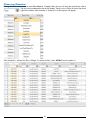
1
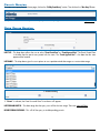
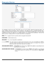
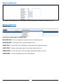
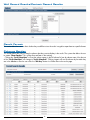
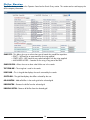
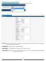
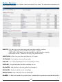
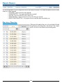
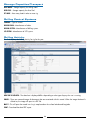
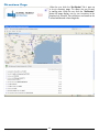
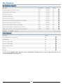
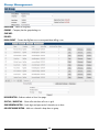
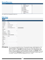
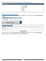
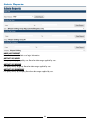
W S
WELL INFORMATION
SYSTEM MANUAL
WELL INFORMATION SYSTEM
System Overview
SCHEDULED QUERIES – This allows the user to set up scheduled
reports that inform them of new activity or permit filings in
regions defined by the user.
DRILLING PERMIT QUERY – Historical permits filed over
the past 25 months complete with Operator address
and contact information. Search the extensive national
RigData database on state, district, county, region, well
orientation, well class, permit type, API, PTD and more.
VIEW YOUR REPORTS – This section allows users to view the
current issue of the standard or special reports to which
they subscribe.
WELL LOCATION & DRILLING ACTIVITY QUERY – Build and save
queries based on drilling contractor, operator, currently
drilling, released, historical spuds, not to mention state,
district, county and region.
BACK ISSUES – This section allows users to view back issues
of the standard or special reports to which they subscribe.
COLUMN TEMPLATES – This allows users to save a list of
columns that can be applied to any query.
RIG SPECIFICATION QUERY – This section allows you to build
queries that show the history of a rig, currently active rigs
and the areas in which they are being used as well as
their individual specifications. We show rig type, power
type, drawworks, horsepower, primary work area as well
as each individual drill associated with that rig.
Revised July 9, 2013
1
List Pages
The List Pages within each of the query type boxes display’s the user’s queries and the user’s shared queries. Here the
user can add new queries and edit the existing queries. The user can also copy existing queries, or go directly to the
results or map pages.
Button Explanation
DATA – This button links directly to the Results Page. The data for the query is displayed.
SCHEDULE QUERY – T his button redirects the user to the Create Schedule Query page. This will allow them to create a new
scheduled query based on the selected query.
MAPS – T his button places markers on a Google map based on the latitude and longitude of the permit or drilling location
that the query returns based on the current query. The marker displays rig and driller information.
DELETE – Deletes the query permanently.
EDIT – Opens the query for editing and allows users to make changes to query criteria.
COPY – C
reates a new copy of the query. Adding “Copy of“ to the query name, the user can then open the query and
rename it or make changes to criteria.
NEW QUERY – Redirects the user to the Edit Query page to create a new query.
DATE RANGES – T he date range boxes on the Permit and Location sections allow the user to change the dates and go
directly to the result data without having to edit the query. To change the range, select different start and
end dates and then select “Data”.
SHARED QUERIES – T his displays the queries that other users have shared with you. Each user can create a query and
share it with anyone within their group thereby allowing others to run the same information inside the
system. These shared queries are read only. However, they can be copied to your queries so one can
make changes to the criteria.
Revised July 9, 2013
2
Permit Queries
To create a new query from the home page, click on the “Drilling Permit Query” section. Then click on the “New Query” Button.
Query Name is used as a description of the query. It can be anything the user wants to enter. This is a required field.
Date Range Section
DATE TYPE – T his drop down allows the user to select “Permit Posted Date” or “Permit Approval Date”. The Permit Posted Date
is the date that the permit was posted with the state. The “Permit Approval Date” is the date that the state
approved the location.
DATE RANGE – This drop down gives the user options to use a predetermined date range or a custom date range.
If “Custom” is selected, the Date From and Date To text boxes will appear.
DATE FROM AND DATE TO – The date range that the query uses to filter the time range. These are required fields.
INCLUDE PENDING CHECK BOX – This will tell the query to include pending permits.
Revised July 9, 2013
3
Geography Section
The Geography Section of the Permit Query allows the user to set the region, state/district and county/parish. This
section is broken into three components. The first component is the region set which is a predetermined area that is
made up of a group of counties or parishes. The region can be one of the RigData standard regions or a custom region
(signified by an *) built in the admin site. The second component is a list of state district combinations. The third is the
county list, which is made up of the list of counties from the first two components.
REGION – This is a group of counties or parishes that are assigned a name and ID.
COUNTY/PARISH – Surface location county.
STATE/DISTRICT – This is a list of state/district combinations.
>, <, >>, << BUTTONS – T he > and < buttons are used to move items between two lists. Users can hold down the “ctrl” key
and select multiple items and move them over all at once using the < or > buttons. The << and >>
buttons are used to move all items from one list to another.
SHOW INLAND WATERS CHECK BOX – A
ll “State/District” items that are of type “Land” will be added or removed based on the
checked status of this check box.
SHOW OFFSHORE DISTRICTS CHECK BOX – A
ll “State/District” items that are of type “Offshore” will be added or removed based
on the checked status of this check box. This will also affect the “County /Parish”
list box
Revised July 9, 2013
4
Well Information Section
PERMIT TYPE – State permit type.
WELL CLASS – Well classification.
PURPOSE – Purpose of the well (Exploratory or Development).
ORIENTATION – Well orientation (Vertical/Horizontal/Directional).
H2S – Denotes whether or not H2S (Hydrogen Sulfide) gas is present (True/False).
API – API Well Number. This can be entered as a comma separated value for multiple API numbers.
(Example: “35-049-24055-A, 05-123- -, 42-003- -, 42-135- -, 42-003- -“).
PTD – Proposed total depth.
LEASE NAME – Registered name on Lease.
Revised July 9, 2013
5
Operator Section
The Operator Section allows the user to search for specific operators to include in the query. First, the user selects the
search type, then they select what field they would like to search by, and finally, they enter the search string. The user
clicks the search button and a list of operators is returned. The user can then add or subtract the operator from the query.
SEARCH TYPE – This allows the user to select what type of search they would like to perform:
• EXACT – Will look for an exact match to the string that is supplied.
• STARTS WITH – Will search for any value that begins with the string supplied.
• ANYWHERE IN FIELD – Searches for the string in any part of the field.
SEARCH FOR FIELD – Allows the user to select what field to use in a search.
TEXT STRING BOX – The string that is used in the search.
RESULTS GRID – This is the grid that displays the results returned by the search.
SELECTED GRID – The grid that displays the operators selected by the user.
ADD BUTTON – Adds an operator on that row to the selected grid.
ADD ALL BUTTON – Adds all operators in the results grid to the selected grid.
REMOVE BUTTON – Removes the operator from the selected grid.
REMOVE ALL BUTTON – Removes all operators from the selected grid.
Revised July 9, 2013
6
Sharing Section
The Sharing Section allows the user to select other users from their group with whom to share the query with.
Output Section
RESULT TYPE
There are six result types to choose from:
WELL RECORD RESULTS – Result set displayed in a grid that can be sorted and exported.
WELL RECORD REPORT – Detail report for the record selected by the user.
CONTACT RESULTS – Contact fields result set displayed in a grid that can be sorted and exported.
CONTACT REPORT – Operator contact detail report for the record selected by the user.
SUMMARY REPORT – A brief well record summary that depicts grouped information with charts.
SCHEDULED QUERY – Creates a scheduled query for the selected query.
Revised July 9, 2013
7
Well Record Results/Contact Record Results
Result Format
This section allows the users to select whether they would like to view the results in a grid or export them to a specific format.
Columns Section
This section allows the users to select the columns that they want to display in the results. The system also allows the user
to create “Column Templates”. This will be discussed later in the training.
Clicking the “Sort By Column Name” will sort the column names in the left column list box by column name. Also the text
of the “Sort By Column Name” will change to “Sort By Column Order”. Clicking it again will sort the columns by the order they
are in the database. After the user clicks the “Run Query” button it will take them to the results page.
Revised July 9, 2013
8
Export File
This result format allows the user to export the result set into various file formats. This can also be done from the results page.
FILE NAME – Name of the file to be exported.
FILE DESCRIPTION – Description of the file that is created.
FILE TYPE – User can select XLS, XLSX, XML or CSV.
After entering this information, the user clicks the “Export” button. This will take the user to the Export Page. They can
then click on the name of the file to download the file. They can also click on the query name to go back and edit the
query that was used to create the exported file.
Revised July 9, 2013
9
Well Record Report/ Contact Report/ Summary Report
After selecting “Well Record Report”, “Contact Report“, or “Summary Report” from the “Result Type” drop down, click the “View
Report” button. The file download will start. The user will be given the option to open or save the file to their local machine.
When the file is open, it will look like one of the following:
Location Summary
2176 Well Starts
NOVEMBER 14, 2011
Currently Active
Rank
Top Operators
Well Starts
Dir/Hoz Cnt
PTD
AVG PTD
1
CHESAPEAKE OPERATING, INC.
Operator
Oklahoma City
137
128
1,505,510
1,505,510
2
PIONEER NATURAL RESOURCES USA, INC.
Irving
56
15
747,773
747,773
3
DEVON ENERGY PRODUCTION COMPANY, LP
Oklahoma City
56
50
607,043
607,043
4
CONTINENTAL RESOURCES, INC.
Enid
41
39
266,318
266,318
5
EOG RESOURCES, INC.
Corpus Christi
31
28
358,800
358,800
6
COG OPERATING, LLC
Midland
31
9
286,317
286,317
7
ANADARKO E & P COMPANY, LP
Houston
28
27
299,824
299,824
8
APACHE CORPORATION
Tulsa
27
6
259,415
259,415
9
WHITING OIL & GAS CORPORATION
Denver
25
22
289,836
289,836
10
CHESAPEAKE APPALACHIA, LLC
Charleston
23
23
155,707
155,707
11
MARATHON OIL COMPANY
Houston
23
23
214,588
214,588
12
SANDRIDGE EXPLORATION & PRODUCTION, LLC
Oklahoma City
22
9
140,163
140,163
13
XTO ENERGY, INC.
Tyler
22
17
346,880
346,880
14
TALISMAN ENERGY USA, INC.
Horseheads
20
20
190,957
190,957
15
EXCO OPERATING COMPANY, LP
Dallas
19
19
267,000
267,000
16
PETROHAWK OPERATING COMPANY
Houston
18
18
241,500
241,500
17
NOBLE ENERGY, INC.
Denver
17
9
131,838
131,838
18
ENDEAVOR ENERGY RESOURCES, LP
Midland
17
1
206,700
206,700
19
XTO ENERGY, INC.
Oklahoma City
17
17
140,412
140,412
20
ENERGEN RESOURCES CORPORATION
Midland
16
6
169,500
169,500
646
486
6,826,081
* Only top 20 points represented
City
COPYRIGHT © 2011 RIGDATA P.O. Box 820547 Fort Worth Texas 76182-0547 1-800-627-9785 | www.rigdata.com
This report is protected under United States and international copyright laws and is intended for the exclusive use of the subscriber. Any unauthorized reproduction, retransmission,
distribution, publication, broadcast or circulation of this report to anyone, directly or indirectly, without the express prior written consent of RIGDATA is prohibited.
To order additional report copies at a reduced rate or for a corporate site license, please contact: 1-800-627-9785
11/14/2011 2:38
Permit Results Report
Revised July 9, 2013
Permit Contact Report
10
Summary Report
Scheduled Query
When the user clicks the “Create Scheduled Query”, the user will be redirected to a page that will allow them create a new
scheduled query. This feature allows the user to schedule a saved query to run and send the results in a selected output
to an email account or FTP site. They are able to schedule this query to run on a monthly, weekly or daily schedule.
OFF/ON DROP DOWN – The user can enable or disable the scheduled query.
RESULT TYPE – This control allows the user to select what type of output the query will return.
FILE DESCRIPTION – Description of the file that is being created and attached to the email.
Revised July 9, 2013
11
FILE TYPE – The possible file types that can be created and attached to the email sent.
• Excel (XLS) Limited to queries that return less than 65,000 records.
• Excel (XLSX) Can be used for queries that return over 65,000 Records.
• XML
• CSV
• PDF
FREQUENCY
– The regularity by which the query is run and emailed to users
• Daily
• Weekly
• Monthly
RECIPIENTS – The list of users that the query is sent to. The query owner is automatically added to the list.
After the user saves the scheduled query, the user will be taken to a list of scheduled queries for that user. From this page
the user can “Edit” a scheduled query or “Delete” them.
Revised July 9, 2013
12
Location Queries
The Location Queries have the same List Pages with the following differences.
CURRENTLY ACTIVE – Used instead of actual dates, represents spud in the past and no release date.
SPUD DATE – Date the rig began drilling the well.
RELEASE DATE – Date the rig was released from the well.
PERMIT POSTED DATE – Date the permit was entered into the RigData System.
PERMIT APPROVAL DATE – Date the permit was approved.
Revised July 9, 2013
13
Driller Section
The Driller Section is similar to the Operator Search on the Permit Query section. This section can be used to query the
driller company information.
SEARCH TYPE – This allows the users to select what type of search they would like to perform:
• EXACT – Will look for an exact match to the string supplied.
• STARTS WITH – Will Search for any value that begins with the string supplied.
• ANYWHERE IN FIELD – Searches for the string in any part of the field.
SEARCH FOR FIELD – Allows the user to select what field to use in the search.
TEXT STRING BOX – The string that is used in the search.
RESULTS GRID – This is the grid that displays the results returned by the search.
SELECTED GRID – The grid that displays the drillers selected by the user.
ADD ALL BUTTON – Adds all drillers in the results grid to the selected grid.
REMOVE BUTTON – Removes the driller from the selected grid.
REMOVE ALL BUTTON – Removes all drillers from the selected grid.
Revised July 9, 2013
14
Output
The ”Contact Report” and “Contact Results” output types have an extra required selection; whether the contact data that is
returned is the driller or operator information.
Revised July 9, 2013
15
Rig Specification Queries
This drop down sets whether the results will include active, inactive or both rig types.
Market/Status
RIG STATUS – S
tatus of the rig (out of service, international, inventory, planned construction, refurb in service, refurbishing,
sold, transferred, under construction).
CURRENT MARKET – Area that rig has or is generally drilling.
OFFSHORE MARKET – General body of water where the rig is or has been drilling.
“LAND/OFFSHORE” drop down – T his control will filter the possible items in the current market and offshore market by land
markets or offshore markets.
Revised July 9, 2013
16
Driller Section
The Driller Section is similar to the Operator Search on the Permit Query section. This section can be used to query the
driller company information.
SEARCH TYPE – T his allows the user to select what type of search they would like to perform:
• EXACT – Will look for an exact match to the string that is supplied.
• STARTS WITH – Will Search for any value that begins with the string that is supplied.
• ANYWHERE IN FIELD – Searches for the string in any part of the field.
SEARCH FOR FIELD – Allows the user to select what field to use in the search.
TEXT STRING BOX – The string that is to be used in the search.
RESULTS GRID – This is the grid that displays the results returned by the search.
SELECTED GRID – The grid that displays the drillers selected by the user.
ADD ALL BUTTON – Adds all drillers in the results grid to the selected grid
REMOVE BUTTON – Removes the driller from the selected grid.
REMOVE ALL BUTTON – Removes all drillers from the selected grid.
RIG NUMBER – As drillers are selected, the rig number list box is updated with the rigs that are associated with that driller.
Revised July 9, 2013
17
Rig Specifications
Because of the amount of data associated with this section, we have given the user the ability to search for specific items
for each field. The user can enter a search string in the textbox and click the “Find” button and it will populate the list
box below. The user can then add the selected items to the query.
MANUFACTURER – Company that built the rig.
MODEL – The model of the rig.
DRAWWORKS – T he hoisting mechanism on a drilling rig. It is essentially a large winch that spools off or takes in the
drilling line and thus lowers or raises the drill stem and bit.
HORSEPOWER FOR FIRST DRAW WORKS – Rated engine horsepower for the drawworks.
DRAWWORKS ENGINE – Manufacturer of the engine in the drawworks.
POWER – Power Type (elec, mech, vfd, scr, ac, dc/dc, hydr).
ENGINE TYPE – A
diesel, LPG, natural gas, or gasoline engine along with a mechanical transmission or generator for
producing power for the drilling rig.
MUD PUMP – D
evice that increases the pressure on a fluid or raises it to a higher level. Various types of pumps include
the bottom hole pump, centrifugal pump, hydraulic pump, jet pump, mud pump, reciprocating pump, rotary
pump, sucker rod pump and submersible pump.
WELL CONTROL – Identifies the well control system used.
MAX DRILLING DEPTH RATING – Maximum drilling depth.
ENGINE HP RATING – Horsepower of the engine.
DRAWWORKS HP RATING – Horsepower rating listed for the drawworks on the rig.
MUD PUMP HP RATING – Horsepower rating for the mud pumps.
Revised July 9, 2013
18
Results Page
The Results Page displays the record set returned by the query in a grid. The user can view detailed information for each
record. The record set can also be sorted in the grid or exported to a format of their choosing.
Results Screen
EDIT QUERY – Redirects to the edit query page.
VIEW MAP – Redirects to the Map Page and plots the result set on a Google map.
EXPORT – Allows the user to export the current result set to Excel, XML or CSV format.
“NUMBER OF RECORDS TO DISPLAY” drop down – D
rop down that allows the user to select a numeric value of records to
view in the results grid.
DETAIL ICON COLUMN
Revised July 9, 2013
– This button is used to view the detail information for this record.
19
Result Export
This result format allows the user to export the result set into various file formats. This section also allows the user to select
what rows will be exported.
• FILE NAME – Name of the file to be exported.
• FILE DESCRIPTION – Description of the file that is created.
• FILE TYPE – User can select XLS, XLSX, XML or CSV.
• EXPORT BUTTON – Exports all of the result set to the file type selected.
• EXPORT SELECTED BUTTON – Only exports the rows that have been checked by user.
Sorting Results
Clicking on the header of any row in the result grid will make
the grid sort by ascending order in that column. Click it again
and it will sort the same column by descending order.
Revised July 9, 2013
20
Filtering Results
Filtering allows the user to create a more defined dataset. To apply a filter, the users will enter the text that they want to
filter by into the textbox below the column header. Then the user will click the funnel icon to the
right of the textbox. After the button is clicked, a list of filter options will appear.
After the option is selected, the filter will begin. To remove the filter, select “No Filter” from the option list.
Revised July 9, 2013
21
Grouping Results
Grouping will organize the result data into related joins based on the column that is used to group the data. For
example – Let us say I want to arrange the result set to have all the records that have the state column equal to Texas
in one section. To do this, the user will click and drag the column header to the gray row above the column headers.
(Orange arrows will identify this row while the user is dragging.)
Now the grid will rebuild, and the user should see a grid that has drill down rows based on the column they selected
to group by.
The users can collapse and open the groups as they wish. To remove the groupings, all the users have to do is click the
column that they added to the group row and drag it back to the grid. The groupings will then be removed.
Revised July 9, 2013
22
Detail Screen
The Detail Section displays specific information for the selected record. The user selects the record by clicking on the
magnifying glass icon in the first column of the record. This will then take them to a detail page where they can view the
information. They can also print the detail information and view the actual scanned document that produced the data.
They can also view the location on a Google map.
API NUMBER – American Petroleum Institute Well Code
LEASE NAME – Lease Name
WELL NUMBER – Surface Location Well Number
STATE NAME – State of Location
COUNTY – County of Location
DISTRICT – District of Location
WELL CLASS – Well Classification
WELL ORIENTATION – W
ell Orientation (Vertical/
Horizontal/Directional)
PROPOSED TOTAL DEPTH – Proposed Total Depth
FIELD NAME – Field 1 of Well
FIELD NAME 2 – Field 2 of Well
FIELD NAME 3 – Field 3 of Well
FIELD NAME 4 – Field 4 of Well
FIELD NAME 5 – Field 5 of Well
COMMENT – Comment Surface
DRILLERNAME – Name of Drilling Company
DRILLER ADDRESS – Address of Drilling Company
DRILLER FAX – Fax Number for Drilling Company
PERMIT APPROVAL DATE – Date Permit was Approved
PERMIT NUMBER – Number on permit
NEW PERMIT FLAG – D
enotes permit filed within the
past 7 days
Revised July 9, 2013
PERMIT TYPE – Work Type (i.e. original drill, workover,
recompletion, sidetrack, etc.)
OPERATOR NAME – Name of Operating Company
CONTACT PERSON – Contact Name in Operating Company
OPERATOR ADDRESS – Address of Operating Company
OPERATOR CITY – City of Operating Company
OPERATOR STATE – State Abbreviation of
Operating Company
OPERATOR ZIP – Zip code of Operating Company
OPERATOR PHONE – Phone Number of
Operating Company
WELL PURPOSE – Purpose of Well
(Exploratory or Development)
H2S FLAG – Denotes whether or not H2S gas (Hydrogen
Sulfide) is present (True/False)
SURFACE LAT – Latitude of Location
SURFACE LONG – Longitude of Location
LEGAL DESCRIPTION – Surface Location Legal Description
DRILLER CONTACT – Contact Name in Drilling Company
DRILLER PHONE – Phone Number of Drilling Company
23
Rig Spec Detail
Company Information
COMPANY – Drilling company.
ADDRESS – Drilling company address.
CITY – Drilling company city.
STATE – Drilling company state.
ZIP – Drilling company zip code.
Summary Specifications
RIG # – Numerical identifier of a rig.
DATE IN SERVICE – Date rig commenced drilling operations.
WORK TYPE – If it is a drilling, work over, spudder, service or a water well rig.
COUNTRY OF ORIGIN – Country that the rig originated.
WORKOVER DEPTH – The maximum depth capacity for a work over rig.
GROSS NOMINAL CAPACITY (GNC) – T he maximum static load with a stated number of drill lines. In a derrick the maximum
load applied at the crown block is equally divided on its 4 legs and is calculated as
follows: GNC=((N+4)/N)*L where N = number of lines to the block and L = maximum
static hook load.
FOOTPRINT (Dimensions) – How large an area is required to set up the rig.
WIND CAPACITY – How many mph it can withstand before blowing over.
SUBSTRUCTURE DESIGN – Manufacturer that made the substructure.
Revised July 9, 2013
24
COOLED BY – A
draw works having an annulus rotating union mounted on ends of the drum spool may be equipped with
an internal brake cooling system that circulates a cooling liquid such as water, oil and the like to the brake
assembly for effectively cooling the brake assembly during operation prevents.
HOOK LOAD – The weight of the drill stem and associated components that are suspended from the hook.
TRAVELING BLOCK AND TON – What kind of blocks and how much it can hold.
HOOK AND TON – H
OOK – A
large, hook-shaped device from which the elevator bails or the swivel is suspended. It turns
on bearings in its supporting housing.
TON – Capacity of the hook in tons.
SWIVEL AND TON – What kind of swivel and how much it can hold.
RIG NAME – Name of the rig.
SUB STRUCTURE – Structure supporting the lower part of the rig.
MANUFACTURER – Maker of the rig.
MINIMUM DRILLING DEPTH – Lowest acceptable depth required to use the rig.
MOUNT – Truck, trailer, carrier, skid.
MAST & DERRICK – The structure used to support the crown blocks and the drillstring of a drilling rig.
MAST – M
asts are usually rectangular or trapezoidal in shape and offer a very good stiffness, important to land rigs
whose mast is laid down when the rig is moved. They suffer from being heavier than conventional derricks
and as a consequence not usually found in offshore environments, where weight is more of a concern than
in land operations.
DERRICK – D
erricks are usually pyramidal in shape, and offer a good strength-to-weight ratio. If the derrick design does
not allow it to be moved easily in one piece, special ironworkers must assemble them piece by piece, and in
some cases disassemble them if they are to be moved.
DRILL LINE – Size of the line that pulls up and down.
FLOOR HT (FT) – Height of the rig floor.
AUXILIARY BRAKE – Brake on the draw works.
ROTARY TABLE – T he principal component of a rotary, or rotary machine, used to turn the drill stem and support the drilling
assembly. It has a beveled gear arrangement to create the rotational motion and an opening into which
bushings are fitted to drive and support the drilling assembly.
RIG TYPE – P
rimarily in offshore, the type of rig it is (barge, platform, semi sub, drillship, coil tubing, jack-up, cable, flex,
or submersible).
LAST ACTIVE – Last release date.
MODEL – Model number supplied by the manufacturer.
MAXIMUM DRILLING DEPTH – Maximum depth that the rig can drill per manufacturer specs.
POWER – Kind of power (elec, mech, vfd, scr, ac, dc/dc, hydr).
HEIGHT – How tall the mast or derrick is.
NUMBER OF LINES – Number of lines it has on the block coming down from the crown.
CLEAR HT(FT) – How tall the blow out preventer (BOP) can be to clear under the table.
TRANS CLUTCH – Transmission from the drawworks.
MAST COLOR – Color of the mast or derrick.
RIG HISTORY – List of owner chain for the rig.
Revised July 9, 2013
25
Draw Works
DRAWWORKS/HP – T he first hoisting mechanism on the rig. It is essentially a large winch that spools off or takes in the
drilling line and thus lowers or raises the drill stem and bit. Horsepower for first drawworks.
DRAWWORKS2/HP – T he second hoisting mechanism on the rig. It is essentially a large winch that spools off or takes in the
drilling line and thus lowers or raises the drill stem and bit and the horsepower for second drawworks.
DRAWWORKS ENGINE 1/HP – The engine and horsepower.
DRAWWORKS ENGINE 2/HP – The engine and horsepower.
DRAWWORKS ENGINE 3/HP – The engine and horsepower.
DRAWWORKS ENGINE 4/HP – The engine and horsepower.
TOTAL HP – Total horsepower for the drawworks engines.
Mud System
NUMBER OF TANKS – Number of storage tanks for mud or water.
PUMP 1 – T he first device that increases the pressure on a fluid or raises it to a higher level. Various types of pumps
include the bottom hole pump, centrifugal pump, hydraulic pump, jet pump, mud pump, reciprocating pump,
rotary pump, sucker rod pump and submersible pump.
PUMP 1 POWERED BY – Power type of pump 1.
PUMP 1 HP – Pump 1 horsepower rating.
PUMP 2 – T he second device that increases the pressure on a fluid or raises it to a higher level. Various types of pumps
include the bottom hole pump, centrifugal pump, hydraulic pump, jet pump, mud pump, reciprocating pump,
rotary pump, sucker rod pump and submersible pump.
PUMP 2 POWERED BY – Power type of pump 2.
PUMP 2 HP – Pump 2 horsepower rating.
PUMP 3 – T he third device that increases the pressure on a fluid or raises it to a higher level. Various types of pumps
include the bottom hole pump, centrifugal pump, hydraulic pump, jet pump, mud pump, reciprocating pump,
rotary pump, sucker rod pump and submersible pump.
PUMP 3 POWERED BY – Power type of pump 3.
PUMP 3 HP – Pump 3 horsepower rating.
PUMP 4 – T he fourth device that increases the pressure on a fluid or raises it to a higher level. Various types of pumps
include the bottom hole pump, centrifugal pump, hydraulic pump, jet pump, mud pump, reciprocating pump,
rotary pump, sucker rod pump and submersible pump.
PUMP 4 POWERED BY – Power type of pump 4.
PUMP 4 HP – Pump 4 horsepower rating.
BBL TOTAL CAPACITY – Total barrel capacity.
SHALE SHAKER – A
vibrating screen used to remove cuttings from the circulating fluid in rotary drilling operations. Also
called a shaker.
DE-SILTER – A
centrifugal device, similar to a desander, used to remove very fine particles, or silt, from drilling fluid to
lower the amount of solids in the fluid.
DE-SANDER – A
centrifugal device for removing sand from drilling fluid to prevent abrasion of the pumps. It may be
operated mechanically or by a fast-moving stream of fluid inside a special cone-shaped vessel, in which
case it is sometimes called a hydrocyclone.
DE-GASSER – The equipment used to remove unwanted gas from a liquid, especially from drilling fluid.
Revised July 9, 2013
26
Well Control Equipment
ANNULAR – The space around a pipe in a well bore, sometimes termed the annular space.
DOUBLE RAM – T he closing and sealing component on a blowout preventer. One of three types—blind, pipe, or shear—
may be installed in several preventers mounted in a stack on top of the wellbore. Blind rams, when closed,
form a seal on a hole that has no drill pipe in it; pipe rams, when closed, seal around the pipe; shear
rams cut through drill pipe and then form a seal.
ANNULAR IN – Length of annular in inches.
DOUBLE RAM IN – Double ram size.
ANNULAR PSI – Pressure in an annular space.
DOUBLE RAM PSI – Double pressure capacity.
SINGLE RAM – T he closing and sealing components on a blowout preventer. One of three types—blind, pipe, or shear—
may be installed in several preventers mounted in a stack on top of the wellbore. Blind rams, when closed,
form a seal on a hole that has no drill pipe in it; pipe rams, when closed, seal around the pipe; shear rams
cut through drill pipe and then form a seal.
CHOKE MANIFOLD – T he arrangement of piping and special valves, called chokes, through which drilling mud is circulated
when the blowout preventers are closed to control the pressures encountered during a kick.
SINGLE RAM IN – Length of single ram in inches.
CHOKE MANIFOLD IN – Length of choke manifold in inches.
SINGLE RAM PSI – Pressure capacity in inches.
CHOKE MANIFOLD PSI – Pressure capacity for choke manifold.
ACCUMULATOR – T he storage device for nitrogen pressurized hydraulic fluid, which is used in operating the
blowout preventers.
Power Packages
ENGINE 1 – A
diesel, LPG, natural gas, or gasoline engine along with a mechanical transmission or generator for
producing power for the drilling rig.
ENGINE 1 HP – Engine 1 horsepower.
ENGINE 1 GENERATOR – Manufacturer and possible kilowatts production.
ENGINE 2 – A
diesel, LPG, natural gas, or gasoline engine along with a mechanical transmission or generator for
producing power for the drilling rig.
ENGINE 2 HP – Engine 2 horsepower.
ENGINE 2 GENERATOR – Manufacturer and possible kilowatts production.
ENGINE 3 – A
diesel, LPG, natural gas, or gasoline engine along with a mechanical transmission or generator for
producing power for the drilling rig.
ENGINE 3 HP – Engine 3 horsepower.
ENGINE 3 GENERATOR – Manufacturer and possible kilowatts production.
ENGINE 4 – A
diesel, LPG, natural gas, or gasoline engine along with a mechanical transmission or generator for
producing power for the drilling rig.
ENGINE 4 HP – Engine 4 horsepower.
ENGINE 4 GENERATOR – Manufacturer and possible kilowatts production.
TOTAL HP – A
diesel, LPG, natural gas, or gasoline engine along with a mechanical transmission or generator for
producing power for the drilling rig.
RATED AT – Engine HP and KBA rated for.
SCR SYSTEM – Manufacturer of SCR system.
Revised July 9, 2013
27
Storage Capacities/Transport
DRILL WATER – Storage capacity for drilling water.
DIESEL FUEL – Storage capacity for diesel fuel.
EST LOADS – How many loads it takes to move rig.
Drilling Control Systems
CONTROLS – Type of control.
DRILLERS CABIN – Manufacturer of cabin.
DRILLING SYSTEM – Manufacturer of drilling system.
SCR SYSTEM – Manufacturer of SCR system.
Drilling Activity
This Grid displays the Drilling Activity for rig for the year.
DATA THAT IS DISPLAYED – The data that is displayed differs depending on what type of query the user is running.
IMAGES – T hese are scanned images of documents that are associated with this record. When the image thumbnail is
clicked on, the image will open in a PDF file.
MAP IT – This will open the record in a Google map based on the surface latitude and longitude.
PRINT – Download the detail PDF report.
Revised July 9, 2013
28
Map Page
The Map Page displays the result set as markers on a Google map. Each marker displays a balloon box that that shows
the following information:
PERMIT QUERY
• Surface Latitude
• Surface Longitude
• API
• Operator
• Well
• State/District
• County
• PTD
• Legal Description
LOCATION QUERY
• Surface Latitude
• Surface Longitude
• API
• Operator
• Well
• State/District
• County
• PTD
• Legal Description
• Driller Name
• Driller Address
• Driller Contact
• Driller Phone
Revised July 9, 2013
29
Map Filtering
Using the Attribute box at the top left of the screen, the user can filter the data by checking the box that represents the
column and value that they want to filter by.
After the users have selected the filter values, they click
the “Refresh” button and the grid will rebuild. To remove
the filter, uncheck the attribute that was selected and click
refresh button.
Map Marker Colors
To change the colors of specific markers, the user must first
select an attribute that the color will be determined by.
To do this, select an attribute from the “Map Marker Colors
Determined By” box.
Then go to that attribute in the attribute box and select the
colors from drop down beside the attribute value. After
setting the color values click the “Refresh” button. The grid
will display the new marker colors.
Revised July 9, 2013
30
Directions Page
Revised July 9, 2013
When the user clicks the “Get Directions” link it pops up
a Google directions page. This allows the user to enter
a starting point. When the user clicks the “Get Directions”
button the page displays turn by turn instructions to the
location they selected. These directions are based on the
surface latitude and surface longitude.
31
Column Templates
The Column Template Utility allows users to create custom
column lists that can be used with all queries created by
the Well Information System. The user supplies the column
template a name, then they select a query type (permit,
location or rig spec), and also the columns that they would
like to include in this template. The user then clicks the “Save”
button and the template will now be available.
To use the template, just select it from the “Select a Column
Template from the drop down below“ drop down box.
Revised July 9, 2013
32
My Reports
Lists the current standard reports that the user has subscribed to. Clicking on the icon on the right side of the row will
start the download for that report file.
Revised July 9, 2013
33
REPORT DEFINITIONS
WELL CLASS
CODEDEFINITION
BRD
BRINE DISPOSAL
GLOSSARY
Salt water disposal
BRNBRINE
(GEOLOGY) Water containing more dissolved inorganic salt than typical
seawater. (DRILLING) Saline liquid usually used in completion operations and,
increasingly, when penetrating a pay zone. Brines are preferred because they
have higher densities than fresh water but lack solid particles that might damage
producible formations. Classes of brines include chloride brines (calcium and
sodium), bromides and formates. (DRILLING FLUIDS) A general term that refers
to various salts and salt mixtures dissolved in an aqueous solution. However,
brine can be used more strictly to refer to solutions of sodium chloride. We
prefer to use brine as a general term. The emulsified calcium chloride [CaCl2]
solution (or any other saline phase) in an oil mud is referred to as “brine” or
“brine phase.” The oil/brine ratio, abbreviated OBR, is used to compare solids
content and salinities of oil muds. Clear brines are salt solutions that have few
or no suspended solids. (WELL COMPLETIONS) A water-based solution of
inorganic salts used as a well-control fluid during the completion and workover
phases of well operations. Brines are solids free, containing no particles that
might plug or damage a producing formation. In addition, the salts in brine can
inhibit undesirable formation reactions such as clay swelling. Brines are typically
formulated and prepared for specific conditions, with a range of salts available to
achieve densities ranging from 8.4 to over 20 lbm/gal (ppg) [1.0 to 2.4 g/cmo].
Common salts used in the preparation of simple brine systems include sodium
chloride, calcium chloride and potassium chloride. More complex brine systems
may contain zinc, bromide or iodine salts. These brines are generally corrosive
and costly. (PRODUCTION FACILITIES) Water containing salts in solution, such
as sodium, calcium or bromides. Brine is commonly produced along with oil. The
disposal of oilfield brine is usually accomplished by underground injection into
salt-water saturated formations or by evaporation in surface pits.
CB (GEOLOGY) Naturally-occurring, inflammable organic matter formed from
kerogen in the process of petroleum generation that is soluble in carbon bisulfide.
Bitumen includes hydrocarbons such as asphalt and mineral wax. Typically solid
or nearly so, brown or black, bitumen has a distinctive petroliferous odor (HEAVY
OIL) A designation for a hydrocarbon fluid with a gravity of 10° API or lower,
based upon the classification of the US Department of Energy. (SHALE GAS) The
fraction of naturally occurring, inflammable organic matter that is extractable
from rock using organic solvents. Many petroleum precursors are composed of
bitumen, but most are formed from kerogen in the process of petroleum generation.
Bitumen includes hydrocarbons such as asphalt and mineral wax. Typically
solid or nearly so, brown or black, bitumen has a distinctive petroliferous odor.
Laboratory dissolution with organic solvents allows determination of the amount
of bitumen in samples, an assessment of source rock richness. Burial and heating
of kerogen yield bitumen, then liquid hydrocarbons, and then hydrocarbon gas.
Understanding organic content is especially important in shale reservoirs because
the shale is both the source rock and the reservoir rock in the petroleum system.
Revised July 9, 2013
CRUDE BITUMEN
34
CBM
COAL BED METHANEThe primary energy source of natural gas is a substance called methane (CH4).
Coal bed methane (CBM) is simply methane found in coal seams. It is produced
by non-traditional means, and therefore, while it is sold and used the same as
traditional natural gas, its production is very different. CBM is generated either
from a biological process as a result of microbial action or from a thermal process
as a result of increasing heat with depth of the coal. In 2001, natural gas from
coal beds accounted for approximately 7.9% of total natural gas production in the
United States.
CO2
CO2 WELL
DISDISPOSAL
A well that primarily produces CO2 or carbon dioxide.
well, often a depleted oil or gas well, into which waste fluids can be injected
A
for safe disposal. Disposal wells typically are subject to regulatory requirements
to avoid the contamination of freshwater aquifers.
ERW
ENHANCED RECOVERY WELL
An oil recovery method using sophisticated techniques that alter the original
properties of oil. Once ranked as a third stage of oil recovery that was carried out
after secondary recovery, the techniques employed during enhanced oil recovery
can actually be initiated at any time during the productive life of an oil reservoir.
Its purpose is not only to restore formation pressure, but also to improve oil
displacement or fluid flow in the reservoir. The three major types of enhanced oil
recovery operations are chemical flooding (alkaline flooding or micellar-polymer
flooding), miscible displacement (carbon dioxide [CO2] injection or hydrocarbon
injection), and thermal recovery (steamflood or in-situ combustion). The optimal
application of each type depends on reservoir temperature, pressure, depth, net
pay, permeability, residual oil and water saturations, porosity and fluid properties
such as oil API gravity and viscosity.
FLW
FLOW WELL(FLOWING WELL) A well in which the formation pressure is sufficient to produce
oil at a commercial rate without requiring a pump. Most reservoirs are initially at
pressures high enough to allow a well to flow naturally.
GAS
GAS WELL
A well that primarily produces natural gas.
GDW
GAS DISPOSAL WELL
A well that is for disposing of gas.
GEOGEOTHERMALGeothermal wells are wells which tap into the natural geothermal energy found
beneath the Earth’s crust. There are a number of different types which can be
utilized in various ways, ranging from wells which connect to sources of steam
which can be used to power turbines to wells utilized in geothermal heat pumps,
which maintain stable indoor temperatures with the use of a recirculating water
system. Production wells are geothermal wells which connect to sources of
geothermal energy, while injection wells are designed to force water underground
for the purpose of maintaining a steady supply of water in the geothermal system.
GI
GAS INJECTION WELLA reservoir maintenance or secondary recovery method that uses injected gas
to supplement the pressure in an oil reservoir or field. In most cases, a field
will incorporate a planned distribution of gas-injection wells to maintain reservoir
pressure and effect an efficient sweep of recoverable liquids.
GRW
GAS RELIEF WELLA well drilled to relieve pressure on the main well to pull out the gas/oil (i.e. BP
had 3 relief wells in the gulf).
GST
GEOLOGIC STRUCTURE TEST Exploritory testing of the geological structure of the ground.
Revised July 9, 2013
35
A well to store gas already pulled from the ground.
GSW
GAS STORAGE WELL
INJ
INJECTION WELLA well in which fluids are injected rather than produced, the primary objective
typically is to maintain reservoir pressure. Two main types of injection are common:
gas and water. Separated gas from production wells or possibly imported gas
may be reinjected into the upper gas section of the reservoir. Water-injection
wells are common offshore, where filtered and treated seawater is injected into a
lower water-bearing section of the reservoir.
N/A
NOT APPLICABLE
O/G
OIL & GAS WELLA combination of oil and gas is found during drilling or is on the permit because
operator not sure of which or both will be found.
OIL
OIL WELLA producing well with oil as its primary commercial product. Oil wells almost
always produce some gas and frequently produce water. Most oil wells eventually
produce mostly gas or water.
PSD
PIERCEMENT SALT DOMELargely subsurface geologic structure that consists of a vertical cylinder of salt
(including halite and other evaporites) 1 km (0.6 mile) or more in diameter,
embedded in horizontal or inclined strata. In the broadest sense, the term includes
both the core of salt and the strata that surround and are “domed” by the core.
Similar geologic structures in which salt is the main component are salt pillows
and salt walls, which are related genetically to salt domes, and salt anticlines,
which are essentially folded rocks pierced by upward migrating salt. Salt domes
make excellent traps for hydrocarbons because surrounding sedimentary strata
are domed upward and blocked off. Major accumulations of oil and natural
gas are associated with domes in the United States, Mexico, the North Sea,
Germany, and Romania. In the Gulf Coastal Plain of Texas and Louisiana, salt
domes will be a significant source of hydrocarbons for some years to come. Huge
supplies of oil have been found in salt dome areas off the coast of Louisiana.
SFW
STEAM FLOOD WELLA secondary recovery production system that utilizes steam injection
to reduce the viscosity of highly viscous oil, enabling viable production
rates. A method of thermal recovery in which steam generated at surface
is injected into the reservoir through specially distributed injection wells.
When steam enters the reservoir, it heats up the crude oil and reduces its
viscosity. The heat also distills light components of the crude oil, which
condense in the oil bank ahead of the steam front, further reducing the
oil viscosity. The hot water that condenses from the steam and the steam
itself generate an artificial drive that sweeps oil toward producing wells.
Another contributing factor that enhances oil production during steam injection is
related to near-wellbore cleanup. In this case, steam reduces the interfacial tension
that ties paraffins and asphaltenes to the rock surfaces while steam distillation of
crude oil light ends creates a small solvent bank that can miscibly remove trapped oil.
Steamflooding is also called continuous steam injection or steam drive.
STR
STRAT TEST
well drilled to test the statigraphy of an area to determine if the strata is likely
A
to contain hydrocarbons.
SUL
SULPHUR WELL
Well that produces sulpher.
Revised July 9, 2013
36
SWD
SALTWATER DISPOSAL WELLOil and gas reservoirs are usually found in porous rocks, which also contain
saltwater. This saltwater, which accompanies the oil and gas to the surface, can
be disposed in two ways: 1) Returned by fluid injection into the reservoir where
it originated from for secondary or enhanced oil recovery; or 2) Injected into
underground porous rock formations not productive of oil or gas, and sealed
above and below by unbroken, impermeable strata. Saltwater disposal wells use
this second method to manage saltwater.
WD
WATER DISPOSAL WELL
WFW
WATER FLOOD WELL(WATER FLOODING) A method of secondary recovery in which water is injected
into the reservoir formation to displace residual oil. The water from injection wells
physically sweeps the displaced oil to adjacent production wells.
WIW
WATER INJECTION WELLA well to inject water into the ground to frac/crack the shale to release the gas.
WMW
WATER MONITORING WELL
well to monitor the water in reservoir and/or the water supply to ensure no gas
A
or oil is found in the water supply.
WSW
WATER SUPPLY WELL
A well to supply water for drilling.
Revised July 9, 2013
The same as saltwater disposal well but with fresh water.
37
WORK TYPE
CODEDEFINITION
GLOSSARY
BPBYPASS
Intentional sidetracks used to bypass an unusable section of the original wellbore
or explore a geologic feature nearby. The secondary wellbore is usually drilled
substantially parallel to the original well, which may be inaccessible due to an
irretrievable fish, junk in the hole, or a collapsed wellbore.
CLRECLASSIFICATION C
hanging an existing well originally permitted only as injection/disposal or other
service well to an oil or gas producing well or changing an existing well from oil
to gas or gas to oil production
COCOMPLETION
A generic term used to describe the events and equipment necessary to bring a
wellbore into production once drilling operations have been concluded, including
but not limited to the assembly of downhole tubulars and equipment required to
enable safe and efficient production from an oil or gas well. Completion quality
can significantly affect production from shale reservoirs.
CVCONVERSION
Converted from oil/gas well to disposal well.
DEDEEPENING
To drill deeper.
HOHORIZONTALIZE
To go horizontal.
LTLATERAL
The horizontal leg or legs of a well. There can be one or several laterals drilled
from a single vertical borehole. Horizontal lateral sections can be designed to
intersect natural fractures or simply to contact more of the productive formation.
OD
ORIGINAL DRILLING
Original drilling is first permit and first hole in the ground.
PA
PLUG & ABANDON
(DRILLING) To prepare a well to be closed permanently, usually after either logs
determine there is insufficient hydrocarbon potential to complete the well, or after
production operations have drained the reservoir. Different regulatory bodies
have their own requirements for plugging operations. Most require that cement
plugs be placed and tested across any open hydrocarbon-bearing formations,
across all casing shoes, across freshwater aquifers, and perhaps several other
areas near the surface, including the top 20 to 50 ft [6 to 15 m] of the wellbore.
The well designer may choose to set bridge plugs in conjunction with cement
slurries to ensure that higher density cement does not fall in the wellbore. In
that case, the bridge plug would be set and cement pumped on top of the plug
through drillpipe, and then the drillpipe withdrawn before the slurry thickened.
(WELL COMPLETIONS) To prepare a wellbore to be shut in and permanently
isolated. There are typically regulatory requirements associated with the P&A
process to ensure that strata, particularly freshwater aquifers, are adequately
isolated. In most cases, a series of cement plugs is set in the wellbore, with an
inflow or integrity test made at each stage to confirm hydraulic isolation.
PB
PLUG BACK
To plug the hole and go another direction (plug with cement).
RCRECOMPLETION
After well is completed to go back in and recomplete the well.
RDRE-DRILL
To re-drill the well.
RERE-ENTRY
To re-enter the well to re-drill.
Revised July 9, 2013
38
RTRE-TEST
To test the well again.
STSIDETRACK
To drill a secondary wellbore away from an original wellbore. A sidetracking
operation may be done intentionally or may occur accidentally. Intentional
sidetracks might bypass an unusable section of the original wellbore or explore
a geologic feature nearby. In the bypass case, the secondary wellbore is usually
drilled substantially parallel to the original well, which may be inaccessible due
to an irretrievable fish, or a collapsed wellbore. It is possible to have multiple
sidetracks that might be drilled for different reasons.
TTTEST
Test well for flow.
WOWORKOVER
(DRILLING) The repair or stimulation of an existing production well for the purpose
of restoring, prolonging or enhancing the production of hydrocarbons. (WELL
WORKOVER & INTERVENTION) The process of performing major maintenance
or remedial treatments on an oil or gas well. In many cases, workover implies
the removal and replacement of the production tubing string after the well has
been killed and a workover rig has been placed on location. Through-tubing
workover operations, using coiled tubing, snubbing or slickline equipment, are
routinely conducted to complete treatments or well service activities that avoid a
full workover where the tubing is removed. This operation saves considerable time
and expense.
Revised July 9, 2013
39
RIG TYPE
CODEDEFINITION
GLOSSARY
BARGBARGE
A barge floats on top of the water and has a rig on top for shallow water
drilling only.
JKUPJACK-UP
self-contained combination drilling rig and floating barge, fitted with long
A
support legs that can be raised or lowered independently of each other. The
jackup, as it is known informally, is towed onto location with its legs up and the
barge section floating on the water. Upon arrival at the drilling location, the legs
are jacked down onto the seafloor, preloaded to securely drive them into the
seabottom, and then all three legs are jacked further down. Since the legs have
been preloaded and will not penetrate the seafloor further, this jacking down of
the legs has the effect of raising the jacking mechanism, which is attached to the
barge and drilling package. In this manner, the entire barge and drilling structure
are slowly raised above the water to a predetermined height above the water, so
that wave, tidal and current loading acts only on the relatively small legs and not
the bulky barge and drilling package.
PLATPLATFORM
An immobile offshore structure from which development wells are drilled and
produced. Platform rigs may be built of steel or concrete and may be either rigid
or compliant. Rigid platform rigs, which rest on the seafloor, are the caisson-type
platform, the concrete gravity platform, and the steel-jacket platform. Compliant
platform rigs, which are used in deeper waters and yield to water and wind
movements are the guyed-tower platform and the tension-leg platform.
SEMISEMI-SUBMERSIBLE
floating offshore drilling unit that has pontoons and columns that when flooded
A
cause the unit to submerge in the water to a predetermined depth. Living quarters,
storage space, and so forth are assembled on the deck. Semisubmersible rigs are
either self-propelled or towed to a drilling site and either anchored or dynamically
positioned over the site, or both. In shallow water, some semisubmersibles can be
ballasted to rest on the seabed. Semisubmersibles are more stable than drill ships
and ship-shaped barges and are used extensively to drill wildcat wells in rough
waters such as the north sea. Two types of semisubmersible rigs are the bottletype semisubmersible and the column-stabilized semisubmersible.
SHIP
aritime vessel modified to include a drilling rig and special station-keeping
M
equipment. The vessel is typically capable of operating in deep water. A drillship
must stay relatively stationary on location in the water for extended periods
of time. This positioning may be accomplished with multiple anchors, dynamic
propulsion (thrusters) or a combination of these. Drillships typically carry larger
payloads than semisubmersible drilling vessels, but their motion characteristics are
usually inferior.
DRILL SHIP
SUBSUBMERSIBLE
A particular type of floating vessel that is supported primarily on large pontoonlike structures submerged below the sea surface. The operating decks are elevated
100 or more feet [30 m] above the pontoons on large steel columns. Once on
the desired location, this type of structure is slowly flooded until it rests on the
seafloor. After the well is completed, the water is pumped out of the buoyancy
tanks, the vessel refloated and towed to the next location. Submersibles, as they
are known informally, operate in relatively shallow water, since they must actually
rest on the seafloor.
Revised July 9, 2013
40
DRILLING TERMS
CODEDEFINITION
GLOSSARY
TKTURNKEY
Although they vary in form, all turnkey contracts generally have three features
in common. First, a turnkey contract has a basic obligation to drill a well to a
certain depth or formation. Second, a turnkey contract has a fixed price in which
the contractor earns the entire price if the contractor performs and reaches the
specific depth and complies with whatever other obligations are included in the
“turnkey obligation.” Third, the contractor controls the operation and the drilling
methods because the contractor takes the risk of losing the well. A pure turnkey
contract provides the highest risk and highest reward for the contractor. Under
this type of contract, a drilling contractor is obligated to drill a complete well for
a lump sum, fixed fee. The contractor assumes all costs and practically all risks
of the job, and it contracts with third parties for equipment and services. Thus,
operators use turnkey contracts to limit the risk inherent in drilling wells. If there
are difficulties during the operation and the turnkey depth is not reached, the
contractor is not paid; obviously, the contractor assumes substantially more risk
than it does during daywork operations, at least during “turnkey” operations. This
risk transfer accounts for the higher cost to the operator of turnkey operations. The
reward can be very lucrative for the contractor if the well is completed ahead of
schedule and below budget; however, the contractor could also be exposed to
significant potential losses. Despite the name, a turnkey contract usually has the
operator responsible for the cost and obligation of completing and equipping
the well. A turnkey contract, however, may be tailor-made to particular drilling
conditions, placing specified risks on the operator and providing additional
compensation to the drilling contractor.
FTFOOTAGE
Revised July 9, 2013
“footage” contract basically provides that the drilling contractor furnishes the
A
drilling crew, drilling equipment, and certain specified services, and is paid an
agreed sum of money for each foot actually drilled; the drilling contractor receives
a stipulated price per foot of hole drilled from the surface to a certain depth or
to some specified objective. The contractor assumes more of well-related risk
under a footage basis than under a daywork contract, which is balanced by
a somewhat higher cost to the operator. If the contractor is able to drill more
efficiently than projected, the profitability of that contract improves. But if the well
encounters problems and costs more per foot of well drilled, the drilling contractor
picks up the added cost and may lose money. Daywork compensation rates may
apply when the drilling is suspended or delayed. If daywork rates apply, then
so do the risk allocation provisions of a daywork contract. Thus, it is important
to specifically define in a footage contract when daywork rates apply. Because
the drilling contractor is only paid for footage drilled and for specified daywork,
and because the contractor assumes more risk, the footage contract may be
more advantageous for the operator. Under all forms, the operator will generally
reserve the right to order that drilling cease at any point in time. The contractor’s
right to stop drilling, however, is more limited. Generally, a contractor may stop
drilling if there is concern over the operator’s solvency, if the operator has failed to
compensate the contractor in a timely manner, or if unanticipated problems arise
beyond the contractor’s control.
41
DW
DAY WORK
“daywork” contract provides that the drilling contractor be paid a certain price
A
or rate for work performed as requested by the operator over a twenty-four-hour
period with the contractor assuming only certain risks. A daywork contract is a
simple matter of contracting out a drilling rig with a specified crew to an oil and
gas operator for a flat daily fee. If problems are encountered in the well, the
drilling contractor generally continues to get paid a dayrate for as long as it takes
to complete the well. The amount of the stipulated rate depends on many factors,
including market conditions, the type of rig, size of the crew, stage of performance,
and specialization of the work. The rate may be proportionately lowered under
certain circumstances. For instance, if the rig is on “standby,” salaries of the
drilling contractor’s crew continue; however, operating expenses do not accrue.
Thus, the standby rate should theoretically be lower than the daywork rate, but
that is usually not the case. Under the daywork contract, the driller is responsible
for specified risks whereas the operator assumes the general risk of delay and
any other performance risks not assumed by the driller. During the past decade,
there has been a substantial shift away from footage and turnkey contracts to
more daywork contracts. In fact, since 2001, more than 75% of the land drilling
contracts in the U.S. have been on a daywork basis. This figure is up from less
than 45% daywork contracts only ten years ago. Drilling contractors recognize
that daywork drilling operations are generally the least risky, considering the
contractor receives a fixed amount of revenue per operating day regardless of
how efficiently the hole is drilled.
DRILLING ACTIVITY
CODEDEFINITION
ASD
AS DIRECTED
GLOSSARY
Operator has informed driller that information cannot be disclosed (it would be
part of the contract).
ASNASSIGNED
Driller has contract but rig has not moved onto drilling site.
ATD
AT TOTAL DEPTHDrilled as far as they can go (if drilling goes past PTD state can fine driller/
operator).
CIRCIRCULATE
Circulating mud around the casing while drilling.
COMCOMPLETION
Completion rig on-site doing completion of well to get well ready for production.
DMBDEMOBILIZE
DRL
DRLG AHEAD
Currently drilling.
LDP
LAYING DOWN DRILL PIPE
Removing drill pipe from wellbore.
LOGLOGGING
Probe to measure density depth to ensure right.
MOBMOBILIZING
MOL
MOVING ON
Rig moving onto new location.
MONMONITORING
Monitor well at end to ensure production.
NTD
NEAR TOTAL DEPTH
Driller is drilling close to the total depth of the well.
P&A
PLUG & ABANDON
Hole plugged (dry well, end of production) and abandoned.
Revised July 9, 2013
42
POH
P.O.O.H. – PULLING OUT OF HOLE
RCG
RUN CASING
Pulling bit out of hole.
unning the casing down the pipe after drilling. This can be surface casing,
R
intermediate casing or production casing.
RCPRECOMPLETE
To re-complete the well.
RELRELEASED
Drilling is complete and the rig has been released by the Operator.
RUP
RIGGING UP
recting the rig. To make ready for use, equipment must typically be moved onto the
E
rig floow, assembled and connected to power sources or pressurized piping systems.
SBY
STAND BYDone with drilling but per contract cannot move to another rig so waiting for
contract to end (stand by pay)
TIH
TRIPPING IN HOLE
TOH
TRIPPING OUT OF HOLEPulling the drillstring out of the hole. A pipe trip is usually done because the bit
has dulled or has otherwise ceased to drill efficiently and must be replaced.
TOW
UNDER TOW
TSTTESTING
Replacing the drill string in the hole after a pipe trip.
Offshore--rig is being towed to the drilling site.
Test the well at the end of the drilling for product.
WOL
WAITING ON LOCATIONRig is waiting to be moved to the drilling site. Could be waiting on permit or
waiting on pad site to be built.
WOO
WAITING ON ORDERS
Waiting for operator to approve start of drilling.
WOW
WAITING ON WEATHER
Waiting on weather so drilling can commence or resume.
WRKWORKOVER
Revised July 9, 2013
T he repair or stimulation of an existing production well for the purpose of restoring,
prolonging or enhancing the production of hydrocarbons.
43
Administration
The Well Information System can be accessed here: www.rigdata.net where the user will need to enter their log-in
and password.
If the user is an Administrator, they will see the “Admin” menu item at the top of the screen:
There are five types of users.
TRIAL – Typical user, no admin rights. Limited data access. Timed trial.
USER – Typical user, no admin rights. They can only change their own password.
ADMIN – C
an only manage their current group, users
and the group’s custom regions. The Admin
Menu item will look like the adjacent image.
SUPER ADMIN – C
an manage their own company,
groups, users and the group’s custom
regions. The Admin Menu item will
look like below.
CORP ADMIN – C
an manage all companies, groups,
users and custom regions. ONLY FOR
RIGDATA ADMINS. Admin Menu item will
look like below.
Revised July 9, 2013
44
Group Management
GROUP NAME – Name of the group.
COMPANY – Company that the group belongs to.
START DATE –
END DATE –
BILLING CONTACT – Contact that RigData uses to correspond about billing issues.
NEW USER BUTTON – Redirects admin to New User page.
SELECT ALL / UNSELECT ALL – Selects all or deselects all users in grid.
SEND CREDENTIALS BUTTON – Sends login and password of selected users to them.
ADD USER TO GROUP BUTTON – Adds user selected in drop down to group.
Revised July 9, 2013
45
Grid Buttons
EDIT – Redirects admin to the Edit User page.
REMOVE – Removes user from group, but doesn’t delete the user.
DELETE – Deletes user from system.
Export File
This exports user information for the users that were selected in the grid, into various file formats.
FILE NAME – Name of the file to export to.
FILE DESCRIPTION – Description of the file that is created.
FILE TYPE – User can select XLS, XML or CSV.
After entering this information the user clicks the “Export” button. This will take the user to the Export Page. They can
then click on the name of the file to download the file.
Sections
Sets the sections that the group has access to.
Regions
Sets the regions that the group has access to.
Revised July 9, 2013
46
State/Districts
Sets State/Districts that group has access to.
Edit User
USER INFORMATION – T his is the general information for the user. The group and company should already be set. The
company and group will be disabled unless the current user is either a Super Admin or Corp
Admin. If the admin is a “Super Admin”, the company drop down will be disabled and the group
admin will only list the groups for the admin’s company. If the admin is a “Corp Admin” then the
company and group drop down will be enabled and list all groups and all companies. The e-mail
is the username. The “Send Credentials” button will send the user their login info and a copy of the
user manual. This button will be not be enabled until the user is saved.
Revised July 9, 2013
47
The export permissions controls will set what sections the user has export abilities on.
Change User Password
Any user can change their password by clicking on the “Account” menu item and then clicking the “Change Password”
sub item.
Enter the new password in the “New Password” and “Confirm Password” text boxes. Then click the “Change Password”
button. If the two text boxes match, the user’s password will be changed.
Revised July 9, 2013
48
Admin Reports
USER LIST REPORT
Lists all active users. Includes user login information.
ACTIVITY BY USER
Lists query activity grouped by user. Based on date range supplied by user.
ACTIVITY BY GROUP
Lists query activity by group. Based on date range supplied by user.
ACTIVITY BY COMPANY
Lists query activity by company. Based on date range supplied by user.
Revised July 9, 2013
49
Custom Regions
The Custom Region list page will display the existing custom regions for the current group. The grid on this page
allows the admin user to add, edit or delete a custom region. By clicking the “Add Region” button, the user will be
redirected to the “View Custom Region” page.
Revised July 9, 2013
50
The user will select existing regions and state/districts. These selections will filter the counties displayed in the Counties
list box. The user will then select the counties that make up the region. The user then clicks the “Save Custom Region” button.
When the user goes to the location or permit query page, they will see the custom region in the region selection List
box. Custom regions are notated with a “ * ” at the beginning of the region name.
Revised July 9, 2013
51