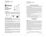
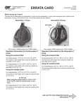
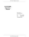
1
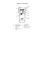
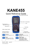
RD99 REFRIGERANT
GAS LEAK DETECTOR
WARNING!
Turn the unit off and remove the battery before cleaning or
replacing sensor. Failure to do so may result in mild electrical
shock or damage to the instrument.
Protection Against Electric Shock
(in accordance with EN 61010-1 : 1993)
This instrument is designated as Class III equipment
and should only be connected to SELV circuits.
1
TABLE OF CONTENTS
PRODUCT FEATURES .....................................3
GENERAL DESCRIPTION ...............................4
OPERATION.....................................................5-8
• BASIC OPERATION
• LOW SENSITIVITY MODE
• HIGH SENSITIVITY MODE
• RESETTING ZERO
EMC....................................................................8-9
BATTERY REPLACEMENT...........................10
SENSOR REPLACEMENT..............................11
SPECIFICATIONS............................................12
WARRANTY INFORMATION .......................13
APPENDIX .........................................................14
2
PRODUCT FEATURES
5
6
1
2
PWR
7
RD99
N L W
HIGH
O
LOW
\
O
OFF
O
FF
3
H IG H
LOW BAT
8
9
4
10
1.
2.
3.
4.
5.
Protective boot
Low battery indicator
Power on light
Audible leak
indicator
Advanced ionisation
sensor
6.
7.
8.
9.
10.
3
Sensor protector
Gooseneck clip
LED array
High/Low/OFF switch
Flexible gooseneck
GENERAL DESCRIPTION
The RD99 is an advanced technology refrigerant
gas leak detector. This detector is capable of
locating any of the current halogen based gases
such as refrigerants. These gases include CFCs,
HCFCs and HFCs.
A partial list of these gases include:
CFCs - R11, R12, R13 etc
HCFCs - R22, R502, R500 etc
HFCs - R134A, R123, R125, R33 etc
This unit will detect other halogen compounds such
as SF6, Perchlorethylene and Halon.
Please contact your distributor or Kane
International Ltd for more information on a specific
application.
This instrument is not to be used in combustible
environments.
4
OPERATION
BASIC OPERATION
1. Turn the instrument ON by sliding the
High/Low/OFF switch to either LOW or HIGH
in a non-contaminated environment i.e. Fresh
air
2. The power light will be illuminated green when
the unit is turned on. If the batteries are too
low to operate the instrument this light will be
RED.
3. The instrument can be switched off at any time
by moving the switch to OFF. It is advisable to
turn off in fresh air.
4. If the tip of the sensor becomes wet shake off
excess and allow to dry naturally.
5
LOW SENSITIVITY MODE
With the switch set to LOW:
5. The LED array will cycle from green to yellow,
and then red indicating the instrument is
performing an auto-zero.
6. Once the auto-zero is complete the green LED
will settle to a steady 2 second flash rate
accompanied by a “bip”. This indicates the
instrument is ready for use.
7. To pinpoint a leak source, move the sensor tip
along the area to be checked. The tick rate will
increase as you approach a leak and the green
LED will flash faster. As concentration of gas
increases the LED array will progressively move
from flashing yellow, orange and red (highest).
8. The tick rate will decrease and the lights will go
out when you move away from the leak source.
6
HIGH SENSITIVITY MODE
To pinpoint the leak or find a very small leak:
9. Set the instrument to HIGH sensitivity using
the slide switch, when switching from LOW to
HIGH sensitivity the top red LED will flash
once.
10. Operation is as in low sensitivity mode but is
more sensitive to small changes in
concentration.
11. Move the tip to levels of higher concentration
indicated by an increase in tick rate and more
lights on the LED array. If the LED array
displays continuously flashing red, turn the
switch to Low Sensitivity and continue.
RESETTING ZERO
12. In fresh air the green LED should settle to a 2
second flash rate accompanied by a blip sound.
7
13. To reset zero in fresh air, turn off the unit for
about 2 seconds then turn on in either LOW or
HIGH sensitivity mode.
ELECTROMAGNETIC
COMPATIBILITY
The European Council Directive 89/336/EEC
requires that electronic equipment does not
generate electromagnetic disturbances that exceed
defined levels and has an adequate level of
immunity to enable it to be operated as intended.
The specific standards applicable to this product
are detailed in the appendices.
Since there are many electrical products in use that
pre-date this Directive and may emit
electromagnetic radiation in excess of the standards
defined in the Directive there may be occasions
where it would be appropriate to check the detector
prior to use. The following procedure should be
adopted:
8
Go through the normal start up sequence in
the location where the equipment is to be
used.
Switch on all localised electrical equipment
that might be capable of causing
interference.
Check that all readings are as expected. (A
level of disturbance in the readings is
acceptable). If not adjust the position of the
instrument to minimise interference or
switch off, if possible, the offending
equipment for the duration of the test.
At the time of writing this manual (Feb 1999) Kane
International Ltd is not aware of any field based
situation where such interference has ever occurred
and this advice is only given to satisfy the
requirements of the Directive.
9
BATTERY REPLACEMENT
1. Remove the battery cover on the back of the
instrument.
2. Replace the 9 volt battery. A lithium or
alkaline battery should always be used. Ensure
the terminals on the battery are the correct
polarity.
3. Replace the battery cover ensuring it is clicked
home and locked in place.
10
SENSOR REPLACEMENT
If the tick rate becomes uncontrollable, it may be
necessary to change the sensor.
We recommend that the sensor should be replaced
at least once a year.
To remove the sensor:
1. Turn the unit off and remove the battery.
2. Unscrew the sensor anti-clockwise from the
gooseneck.
3. Replace with new sensor by turning the sensor
clockwise until finger tight.
WARNING!
Turn the unit off and remove the battery before cleaning or replacing sensor.
Failure to do so may result in mild electrical shock or damage to the
instrument.
11
SPECIFICATIONS
Power Supply:
Sensor:
Sensitivity:
Indicators:
Warm-up:
Response Time:
Duty Cycle:
Battery Life:
Dimensions:
Weight:
Probe Length:
Ambient
Conditions:
One 9V PP3 battery
Advanced ionisation detection
5 gms per year
134A based on LS-20 leak standard
Audible: Auto-zero tick rate
Visual: Flashing LED array
<10 seconds
<1 second
Continuous
Approx 8 hours
180mmH x 70mmW x 35mmD
400gms
400mm
0-40°C, 0-80% RH (noncondensing)
Sensor-tip output
voltage/current: A.
B.
C.
No load high voltage 2500V+10%
Current - 24µA
Loaded high voltage (loaded with
100.1MΩ) 2400V+50V
12
WARRANTY
All Kane International Limited instruments include
batteries and carry a 12 month warranty, covering
any manufacturing defects and component failures.
This warranty applies to all Kane International
Limited products world-wide.
In line with our policy of continuous development
we reserve the right to alter any part of our product
specification without prior notice.
13
APPENDIX
ELECTROMAGNETIC
COMPATIBILITY
This product has been tested for
compliance with the following
generic standards:
EN 50081-1
EN 50082-1
and is certified to be compliant
Specification EC/EMC/KI/RD99
details the specific test configuration,
performance and conditions of use.
14
Thank you for reading this data sheet.
For pricing or for further information, please contact us at our UK Office, using the details
below.
UK Office
Keison Products,
P.O. Box 2124, Chelmsford, Essex, CM1 3UP, England.
Tel: +44 (0)1245 600560
Fax: +44 (0)1245 808399
Email: [email protected]
Please note - Product designs and specifications are subject to change without notice. The user is responsible for determining the
suitability of this product.