1
r o d a
U S E R
R o c k y
I I I +
M A N U A L
The information, instructions and descriptions in this manual are updated and refer to the
pertaining notebook.
The manufacturer reserves the right to make changes to the contents of this manual without
further notice. Proprietor and manufacturer disclaim any warranty as to direct or indirect
damage arising from errors, omissions or deviations between the notebook and the information in the manual.
This manual is protected by copyright. All rights reserved. No part of this manual may be
reproduced or processed, duplicated or disseminated by means of electronic systems in any
form (reproduction, photocopy, scan or other processes) without the written consent of the
proprietor and/or manufacturer.
Copyright © roda Computer GmbH, Lichtenau, Germany, August 2008
Author: Jürgen Ebert, Munich, Germany
Trademark acknowledgments:
IBM and PS/2 are registered trademarks of International Business Machines Corporation.
Microsoft, MS-DOS, Windows and Windows 98, Windows 2000, Windows NT, Windows XP
and Windows Vista are registered trademarks of Microsoft Corporation.
Intel and Pentium are registered trademarks of Intel Corporation.
All other product and proper names mentioned in this manual are proprietary and registered
trademarks/brand names of the respective holders. They only serve as a means of recognition.
Print legend: 1st edition, September 2008
Conventions
This manual is divided into individual chapters with interdependent contents. If you have
experience with the use of computers, you may skip individual chapters or directly look up
the respective keywords.
Some of the explanations and figures contain references marked with the symbol ➩; they
contain further information on the respective topics.
Figure and table numbers correspond with the page you are on. If a page contains several
figures or tables, they are marked a, b, c, etc.
Keys and key combinations are written in square brackets, e.g., [Ctrl] + [Alt] +[F1] means
that you must press the control, Alt and F1 keys simultaneously.
Note
Notes contain important information in connection with the directly related text or chapter.
Attention
You will find the Attention notes where data loss or notebook damage may be the result of
non-compliance with this note.
Warning
Warnings inform you that personal damage or damage to the notebook or individual components thereof may be the consequence of carelessness or non-compliance with the respective warning.
Rocky III+ User Manual
Electromagnetic Compatibility (EMC) and safety instructions
Federal Communications Commission Statement:
This equipment has been tested and found to comply with the regulations for a class-B digital device pursuant to Part 15 of the FCC Rules. These regulations are designed to provide
protection against harmful interference in a resistent installation.
This equipment generates, uses and emits high-frequency radiation and, if not installed and
used in accordance with the instructions, may cause harmful interference to radio communication devices. There is no guarantee that interference will not occur in particular devices. If
this notebook causes interference to radio or television reception, which can be determined
by switching the notebook on and off, the user should implement the following measures:
•
re-align the antenna
•
increase the distance between the notebook and the receiver
•
connect the notebook with another circuit
•
consult the dealer or an qualified radio/TV technician.
Regulatory information / disclaimer
Installation and use of this notebook must be in accordance with the instructions in this
manual. Any changes or modifications made to this notebook (including the antennas) that
have not been approved by the manufacturer may affect the notebook’s functionality and proper operation.
The manufacturer is not responsible for any interference caused due to the unauthorized use
of this notebook or due to the substitution of cables and other equipment. It is the responsibility of the user to correct any such interference. The manufacturer and its authorized resellers or distributors do not assume liability for violation of government regulations arising from
non-compliance with these guidelines.
Important note
FCC RF Radiation Exposure Statement: This equipment also complies with FCC RF
Radiation Exposure Limits under uncontrolled environment. This device and its antenna must
not be located in the proximity of other antennas or transmitters.
CE
Products with the CE symbol comply with both the regulations for Electromagnetic
Compatibility (89/336/EEC) and the Low-Voltage Directive (73/23/EEC) issued by the
Safety instructions a.1
Rocky III+ User Manual
Commission of the European Union.
Compliance with these directives implies conformity with the following European Norms:
EN 55022 (CISPR 22)
EN 55024 (EN61000-4-2, EN61000-4-3, EN61000-4-4, EN61000-4-5, EN61000-4-6,
EN61000-4-8, EN61000-4-11, EN61000-3-2, EN61000-3-3)
EN 60950 (IEC950) Product safety
Declaration of Conformity
Notebook roda Rocky III+ (RK886) and power supply for roda Rocky III+ (RK886):
The above products in the version we have introduced to the market comply with the regulations of the following European guidelines, including all amendments:
73/23/EWG (Low-Voltage Directive), amended by 93/68/EWG, 73/23/EEC (Low-Voltage
Directive), amended by 93/68 EEC, 89/336/EWG (Electromagnetic-Compatibility Directive),
amended by 92/31/EWG; 93/68/EWG 89/336/EEC (Electromagnetic Compatibility), amended
by 92/31/EEC; 93/68/EEC; 98/13/EEC.
The product has been marked with the CE symbol.
The device has been exclusively designed for operation with Rocky III+ with an internal
vehicle adapter in connection with the power-supply unit contained within the delivery scope
of the notebook.
All cables used for external connection of additional devices (e.g., printers, modems, etc.)
must be shielded in accordance with EMI regulations and connected with the respective
additional devices.
UL / TÜV
AC adapter (TÜV encompasses EN60950LVD)
Disposal/recycling
All materials used for manufacturing this notebook are recyclable and environment-friendly.
Neither CFC nor similar materials have been used for manufacturing of this notebook.
a.2 Safety instructions
Rocky III+ User Manual
Please dispose of all packaging materials in accordance with the applicable regulations.
Safety instructions
If possible, unscrew the interface cables manually in order to avoid damage to
the casing threads.
Module-slot screws (battery, hard disk drive and optical drive) should only be
tightened with a coin and NEVER with a screwdriver.
If possible, do not charge the battery in temperatures under 0 °C (32 °F).
Safety instructions a.3
Rocky III+ User Manual
Additional safety instructions for devices with radio components
If your notebook has an integrated radio component (wireless LAN, Bluetooth or UMTS),
please follow these safety instructions when using your notebook:
Switch off the notebook when in a hospital, operation room or near medical electronic systems, since the radio waves transmitted by the radio component can
impair the operation of these medical devices.
If the radio component cannot be switched off, remove the battery or disconnect
the power supply.
Switch off the radio component when on an airplane, unless leaving it on has
been expressly allowed.
Switch off the radio component in blasting areas and in the vicinity of blasting
operations.
Data traffic via a wireless connection can lead to unauthorized persons receiving
the data.
Travelling with the notebook
Travel preparation
Secure important data from the hard disk drive.
Switch off the radio component (wireless LAN/Bluetooth/UMTS) for data-safety
reasons. Data traffic via a wireless connection can lead to unauthorized persons receiving the data.
Travelling abroad
When travelling abroad, make sure that the mains adapter can operate with the
local line voltage. If not, obtain the respective mains adapter for your notebook.
Do not use any other voltage transformers!
Make sure that the local voltage and the specifications for the line cable are
compatible. If not, purchase a line cable that is compatible with the local voltage.
The respective line cable is available as an accessory. Do not use any connection adapters for electronic devices to connect the notebook.
Inquire with the respective authorities of the country of destination whether you
may operate your notebook with the integrated radio component in the respective country (see also "CE identification," page a.2).
You may need a country-specific phone adapter (available as an accessory).
a.4 Safety instructions
Rocky III+ User Manual
Transporting the notebook
Remove all data carriers (e.g., CD or DVD) from the drives.
End the standby mode and shut down the device properly.
Disconnect the mains adapter and all peripherals from the notebook.
Prior to transporting the notebook, remove all ExpressCards in order to avoid
damage.
Close the interface covers.
Use an appropriate notebook casing when transporting the device; this casing is
available as an accessory and offers sufficient space for additional components.
Cleaning the notebook
Switch off the notebook, pull the power plug of the mains adapter from the electrical outlet and uninstall the battery.
Clean the notebook with a water-damp cloth. You may use a mild glass cleaner
for the screen: spray a small amount of the glass cleaner onto a soft, lint-free
cloth and carefully wipe the screen with the cloth.
Do not use strong or caustic cleaners.
Battery maintenance and use
Remove batteries from the notebook if you do not use them over a long period
of time.
Do not touch damaged or leaking Lithium-Ion batteries with bare hands.
Exchange the battery only with a battery of the same or a comparable type
recommended by the manufacturer. Dispose of used batteries in compliance with
the manufacturer’s instructions.
Note that incorrect handling of the battery used in this notebook may lead to fire
or explosion.
Do not disassemble the battery, do not expose it to temperatures above 100 °C
(212 °F) and do not burn it.
Properly dispose of used batteries.
Safety instructions a.5
Rocky III+ User Manual
Warnings concerning the battery
Incorrect handling of batteries may lead to physical damage, severe injury or death. Hence,
we strongly request you follow this advice:
Do not attempt to disassemble, repair or otherwise manipulate the battery. The
battery may overheat and ignite. Discharge of caustic alkaline solution or other
electrolytes from the battery may result in fire or injury.
Do not short-circuit the battery by touching both connectors with a metal object.
Short circuits may result in fire or other damage to the battery leading to injury.
Do not charge the battery in a way other than described in this manual. Do not
connect the battery with an electric outlet or vehicle cigarette lighter.
Only use the battery supplied with the notebook or a battery approved by the
manufacturer. Voltage and polarity of the connecting contacts may vary between
batteries.
The use of an inadequate battery may lead to smoke or fire or to the battery
exploding or igniting.
Do not expose the battery to high temperatures, such as close to a heater. This
may result in the battery igniting, exploding or discharging caustic liquids, which
could result in injury. In addition, it could lead to battery failure or functional battery interruptions resulting in data loss.
Dispose of batteries in accordance with local regulations for hazardous waste.
Warning
Avoid eye, skin and clothes contact with caustic electrolytic liquids from a battery.
Immediately switch off the notebook, disconnect the mains adapter and remove the battery
in any of the following events:
If you notice unusual smells, high heat dissipation, discoloring or deformation of
the battery. Do not use the notebook until it has been checked by Customer
Service. Otherwise, the result may be smoke, fire or battery explosion.
Keep the battery out of reach of children.
a.6 Safety instructions
Rocky III+ User Manual
Attention
Do not dispose of batteries in regular domestic waste. Return them to your dealer or bring them to a recycling center so that resources may be reused and
environmental damage is avoided. Cover the connectors with adhesive tape to
avoid a short circuit resulting in the battery igniting or exploding.
Make sure to insert the battery properly and securely. Otherwise, it could fall out
and cause injury.
Charge the battery in an ambient temperature between 0 and 45 °C (32 and 113
°F). Otherwise, battery performance could decrease and shorten the battery
lifecycle, or the electrolytic liquid could discharge.
Safety instructions a.7
C O N T E N T S
Table of contents Table
of contents Table of
contentsTable of contents Table of contents
Table of contents Table
of contents Table of contents Table of contents
Table of contents Table
of contents Table of contents table of contents
Table of contents Table
of contents Table of contents Table of contents
Table of contents Table
of contents Table of contents Table of contents
Table of contents Table
of contents Table of contents Table of contents
Table of contents Table
of contents Table of contents Table of contents
Table of contents Table
of contents Table of con-
Rocky III+ User Manual
1. Introduction
Front view with open screen . . . . . . . . . . . . . . . . . . . . . . . . . . . . . . . . . . . . . . . . . . . . . .1.2
LED indicators . . . . . . . . . . . . . . . . . . . . . . . . . . . . . . . . . . . . . . . . . . . . . . . . . . . . . . . .1.3
Left-side view . . . . . . . . . . . . . . . . . . . . . . . . . . . . . . . . . . . . . . . . . . . . . . . . . . . . . . . . .1.4
Right-side view . . . . . . . . . . . . . . . . . . . . . . . . . . . . . . . . . . . . . . . . . . . . . . . . . . . . . . . .1.5
Interfaces rear side . . . . . . . . . . . . . . . . . . . . . . . . . . . . . . . . . . . . . . . . . . . . . . . . . . . . .1.6
Bottom view . . . . . . . . . . . . . . . . . . . . . . . . . . . . . . . . . . . . . . . . . . . . . . . . . . . . . . . . . .1.7
2. Commissioning
Preparing the notebook for commissioning . . . . . . . . . . . . . . . . . . . . . . . . . . . . . . . . . . .2.1
Connecting the notebook . . . . . . . . . . . . . . . . . . . . . . . . . . . . . . . . . . . . . . . . . . . . . . . .2.2
Opening and switching on the notebook . . . . . . . . . . . . . . . . . . . . . . . . . . . . . . . . . . . . .2.3
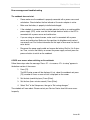
Power-On Self Test (POST) . . . . . . . . . . . . . . . . . . . . . . . . . . . . . . . . . . . . . . . . . . . . . . .2.4
Installing the Windows operating system . . . . . . . . . . . . . . . . . . . . . . . . . . . . . . . . . . . . .2.5
Switching off the notebook . . . . . . . . . . . . . . . . . . . . . . . . . . . . . . . . . . . . . . . . . . . . . . .2.5
3. Operational basics
Keyboard . . . . . . . . . . . . . . . . . . . . . . . . . . . . . . . . . . . . . . . . . . . . . . . . . . . . . . . . . . . .3.1
Integrated numeric keypad . . . . . . . . . . . . . . . . . . . . . . . . . . . . . . . . . . . . . . . . . . . . . . .3.2
Alphanumeric keys . . . . . . . . . . . . . . . . . . . . . . . . . . . . . . . . . . . . . . . . . . . . . . . . . . . . .3.3
Multiple key allocation . . . . . . . . . . . . . . . . . . . . . . . . . . . . . . . . . . . . . . . . . . . . . . . . . . .3.6
Using the touch pad . . . . . . . . . . . . . . . . . . . . . . . . . . . . . . . . . . . . . . . . . . . . . . . . . . . .3.6
TFT screen . . . . . . . . . . . . . . . . . . . . . . . . . . . . . . . . . . . . . . . . . . . . . . . . . . . . . . . . . .3.8
Exchangeable hard disk drive . . . . . . . . . . . . . . . . . . . . . . . . . . . . . . . . . . . . . . . . . . . . .3.10
Optical drive . . . . . . . . . . . . . . . . . . . . . . . . . . . . . . . . . . . . . . . . . . . . . . . . . . . . . . . . . .3.11
Inserting discs . . . . . . . . . . . . . . . . . . . . . . . . . . . . . . . . . . . . . . . . . . . . . . . . . . . . . . . .3.12
PC card and ExpressCard slots . . . . . . . . . . . . . . . . . . . . . . . . . . . . . . . . . . . . . . . . . . .3.14
Inserting a PC card . . . . . . . . . . . . . . . . . . . . . . . . . . . . . . . . . . . . . . . . . . . . . . . . . . . . .3.15
Table of contents I
Rocky III+ User Manual
Inserting an ExpressCard . . . . . . . . . . . . . . . . . . . . . . . . . . . . . . . . . . . . . . . . . . . . . . . .3.17
Installing and uninstalling notebook modules . . . . . . . . . . . . . . . . . . . . . . . . . . . . . . . . .3.19
Removing the primary battery . . . . . . . . . . . . . . . . . . . . . . . . . . . . . . . . . . . . . . . . . . . . .3.20
4. Power supply and energy management
Power supply for the notebook . . . . . . . . . . . . . . . . . . . . . . . . . . . . . . . . . . . . . . . . . . . .4.1
Battery operation . . . . . . . . . . . . . . . . . . . . . . . . . . . . . . . . . . . . . . . . . . . . . . . . . . . . . .4.2
Using the energy-saving modi . . . . . . . . . . . . . . . . . . . . . . . . . . . . . . . . . . . . . . . . . . . . .4.6
Setting the energy-saving functions . . . . . . . . . . . . . . . . . . . . . . . . . . . . . . . . . . . . . . . .4.6
Standby mode . . . . . . . . . . . . . . . . . . . . . . . . . . . . . . . . . . . . . . . . . . . . . . . . . . . . . . . . .4.7
Idle state . . . . . . . . . . . . . . . . . . . . . . . . . . . . . . . . . . . . . . . . . . . . . . . . . . . . . . . . . . . . .4.7
Vehicle adapter . . . . . . . . . . . . . . . . . . . . . . . . . . . . . . . . . . . . . . . . . . . . . . . . . . . . . . . .4.9
5. BIOS setup
Starting BIOS setup . . . . . . . . . . . . . . . . . . . . . . . . . . . . . . . . . . . . . . . . . . . . . . . . . . . .5.1
BIOS setup menu . . . . . . . . . . . . . . . . . . . . . . . . . . . . . . . . . . . . . . . . . . . . . . . . . . . . . .5.1
Main setup . . . . . . . . . . . . . . . . . . . . . . . . . . . . . . . . . . . . . . . . . . . . . . . . . . . . . . . . . . .5.3
Advanced setup . . . . . . . . . . . . . . . . . . . . . . . . . . . . . . . . . . . . . . . . . . . . . . . . . . . . . . .5.4
Security setup . . . . . . . . . . . . . . . . . . . . . . . . . . . . . . . . . . . . . . . . . . . . . . . . . . . . . . . . .5.7
Boot setup . . . . . . . . . . . . . . . . . . . . . . . . . . . . . . . . . . . . . . . . . . . . . . . . . . . . . . . . . . .5.9
Exit setup . . . . . . . . . . . . . . . . . . . . . . . . . . . . . . . . . . . . . . . . . . . . . . . . . . . . . . . . . . . .5.10
6. Driver software
MS-Windows XP and Windows Vista . . . . . . . . . . . . . . . . . . . . . . . . . . . . . . . . . . . . . . . .6.1
VGA driver . . . . . . . . . . . . . . . . . . . . . . . . . . . . . . . . . . . . . . . . . . . . . . . . . . . . . . . . . . .6.1
USB driver . . . . . . . . . . . . . . . . . . . . . . . . . . . . . . . . . . . . . . . . . . . . . . . . . . . . . . . . . . .6.2
Touchsreen driver . . . . . . . . . . . . . . . . . . . . . . . . . . . . . . . . . . . . . . . . . . . . . . . . . . . . . .6.2
PCMCIA driver . . . . . . . . . . . . . . . . . . . . . . . . . . . . . . . . . . . . . . . . . . . . . . . . . . . . . . . .6.3
II Table of contents
Rocky III+ User Manual
Audio driver . . . . . . . . . . . . . . . . . . . . . . . . . . . . . . . . . . . . . . . . . . . . . . . . . . . . . . . . . .6.3
LAN driver . . . . . . . . . . . . . . . . . . . . . . . . . . . . . . . . . . . . . . . . . . . . . . . . . . . . . . . . . . . .6.3
Mini PCI-E WLAN driver . . . . . . . . . . . . . . . . . . . . . . . . . . . . . . . . . . . . . . . . . . . . . . . . .6.3
Fax/modem driver . . . . . . . . . . . . . . . . . . . . . . . . . . . . . . . . . . . . . . . . . . . . . . . . . . . . . .6.3
Bluetooth driver . . . . . . . . . . . . . . . . . . . . . . . . . . . . . . . . . . . . . . . . . . . . . . . . . . . . . . . .6.3
A. Annex
Technical data . . . . . . . . . . . . . . . . . . . . . . . . . . . . . . . . . . . . . . . . . . . . . . . . . . . . . . . .A.1
Environment characteristics . . . . . . . . . . . . . . . . . . . . . . . . . . . . . . . . . . . . . . . . . . . . . .A.3
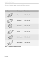
Options and accessories . . . . . . . . . . . . . . . . . . . . . . . . . . . . . . . . . . . . . . . . . . . . . . . .A.4
Error messages and troubleshooting . . . . . . . . . . . . . . . . . . . . . . . . . . . . . . . . . . . . . . . .B.1
Service and support . . . . . . . . . . . . . . . . . . . . . . . . . . . . . . . . . . . . . . . . . . . . . . . . . . . .B.3
International power plugs . . . . . . . . . . . . . . . . . . . . . . . . . . . . . . . . . . . . . . . . . . . . . . . .B.4
Index register . . . . . . . . . . . . . . . . . . . . . . . . . . . . . . . . . . . . . . . . . . . . . . . . . . . . . . . . . .i.1
Table of contents III
1
C H H P T E R
IntroductionIntroduction
IntroductionIntroduction
IntroductionIntroduction
IntroductionIntroduction
IntroductionIntroduction
IntroductionIntroduction
IntroductionIntroduction
IntroductionIntroduction
IntroductionIntroduction
IntroductionIntroduction
IntroductionIntroduction
IntroductionIntroduction
IntroductionIntroduction
IntroductionIntroduction
IntroductionIntroduction
IntroductionIntroduction
IntroductionIntroduction
IntroductionIntroduction
IntroductionIntroduction
IntroductionIntroduction
IntroductionIntroduction
IntroductionIntroduction
IntroductionIntroduction
IntroductionIntroduction
Rocky III+ User Manual
Introduction
The Rocky III+ notebook allows the operation under extreme environmental conditions. All interfaces and
slots are covered separately. The casing is equipped with rubber bumpers and provides a maximum of
protection against shock, vibration, dust and humidity. The technical details are listed in the Annex.
Checking the standard scope of delivery
The following lists the standard scope of delivery for the notebook.
Please use this list to check the package contents for completeness. Contact your dealer if
one or more of the following listed items is not contained in the package.
•
power cable
•
external power-supply unit
•
driver CD
•
notebook
•
battery (may be installed).
The following pages provide you with an overview of the notebook’s main operation elements
and connections.
Introduction 1.1
Rocky III+ User Manual
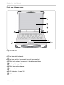
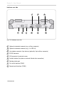
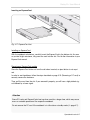
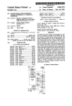
Front view with open screen
8
7
6
1
5
4
2
Fig. 1.2: Front view
1
Left integrated loudspeaker
2
Left touch pad key (corresponds to the left mouse button)
3
Right touch pad key (corresponds to the right mouse button)
4
Touch pad (➩ page 3.6)
5
Right integrated loudspeaker
6
Power-on button
7
LED indicators (➩ page 1.3)
8
LCD screen
1.2 Introduction
3
Rocky III+ User Manual
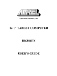
LED indicators
Fig. 1.3: LED indicators
1
2
3
4
5
6
7
8
1
WLAN indicator
2
PCMCIA card indicator
3
Num Lock indicator (➩ page 3.2)
4
Caps Lock indicator (➩ page 3.3)
5
Scroll Lock indicator (➩ page 3.4)
6
HDD-in-use indicator
7
Indicator for secondary battery charge status (in the CD-ROM or FDD slot)
8
Indicator for primary battery charge status
9
Power indicator
9
Introduction 1.3
Rocky III+ User Manual
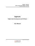
Left-side view
1
5
9
7
3
11
10
4
2
6
8
12
13
Fig. 1.4: Left-side view
1
PS/2 connector for external mouse/keyboard
2
Ethernet RJ45 (optionally: FiberOptic 100MB or 1GB)
3
FireWire 1394
4
FireWire 1394
5
USB 2.0
6
USB 2.0
7
PC card type II slot
8
PC ExpressCard slot (optionally: PC card type II)
9
Line-out
10
Line-in
11
Microphone-in (Mic-in)
12
Optional customized port (2 x serial RS232/RS422/RS485)
13
Modem connector RJ11(optionally: LAN RJ45, FiberOptic 100MB or 1GB)
1.4 Introduction
Rocky III+ User Manual
Right-side view
1
4
5
2
3
Fig. 1.5: Right-side view with DVD drive
1
DVD drive (optionally: DVD-RW, Dual Drive, secondary battery, FDD)
2
DVD-in-use indicator
3
DVD-eject button
4
DVD-emergency-eject slot
5
Exchangeable hard disk drive
Introduction 1.5
Rocky III+ User Manual
Interfaces rear side
5
1
2
3
4
7
6
9
8
Fig. 1.6: Interfaces rear side
1
Optional customized connector (e.g., military connector)
2
Optional customized connector (e.g., 2 x USB 2.0)
3
Line adapter connector 2-pin industry (optionally: 3-pin military connector)
4
DP DVI connector
5
VGA connector for external screen
6
Parallel interface (for printer or external diskette drive connection)
7
Docking-station port
8
First serial interface (COM1)
9
Second serial interface (COM2)
1.6 Introduction
Rocky III+ User Manual
Bottom view
1
2
3
5
4
Fig. 1.7a: Bottom view
1
Device-type label
2
Module-slot screw for exchangeable hard disk drive
3
Module-slot screw for DVD-RW drive / secondary battery
4
Module-slot screw for primary battery
5
Primary battery and adhesive with device serial number (underneath the battery)
A second adhesive with the device serial
number (SN) is located underneath the
battery module.
You will need this serial number for inquiries with the Service Hotline and sending
the notebook for repair (➩ Annex B.3).
The current BIOS version will be briefly
displayed after you switch on the notebook
(Fig. 2.4, Boot sequence).
Fig. 1.7b: Adhesive with serial number
Introduction 1.7
2
C H H P T E R
CommissioningCommissi
oningCommissioningCo
mmissioningCommission
ingCommissioningComm
issioningCommissioning
CommissioningCommissi
oningCommissioningCo
mmissioningCommission
ingCommissioningComm
issioningCommissioning
CommissioningCommissi
oningCommissioningCo
mmissioningCommission
ingCommissioningComm
issioningCommissioning
CommissioningCommissi
oningCommissioningCo
mmissioningCommission
ingCommissioningComm
issioningCommissioning
CommissioningCommissi
oningCommissioningCo
mmissioningCommission
ingCommissioningComm
Rocky III+ User Manual
Preparing the notebook for commissioning
Remove the notebook from the packaging and set it on a surface with the bottom side facing
up.
Fig. 2.1a: Opening the battery screw
Use a coin to turn and open the battery-module slot screw so that you can remove the battery and the plastic insulator underneath it.
Fig. 2.1b: Removing the insulator
Remove the insulator, re-insert the battery module and tighten the safety screw. Mind the
leveling of the screw so that the battery cannot fall out.
Commissioning 2.1
Rocky III+ User Manual
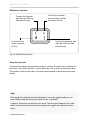
Connecting the notebook
Place the notebook on a stable surface.
Connect the line cable (1) with the power-supply unit (2) and plug the plug into the electrical
outlet. The green LED (4) will illuminate as soon as the power-supply unit is connected with
the outlet, regardless whether the connection with the notebook has been successful.
5
4
3
2
1
Fig. 2.2: Connecting the notebook
Plug the DC plug (3) of the power-supply unit into the DC input (5) of the notebook and tighten the knurled screw. The battery-charge lamp on the notebook will also illuminate (➩ Fig.
1.3).
Charge the notebook for at least 10 minutes.
Note
The enclosed line cable complies with the specifications of the country in which the notebook was purchased. Please ensure that the line cable has been approved for the country
in which the notebook will be used. Find further information on country-specific power-plug
versions in the Annex.
2.2 Commissioning
Rocky III+ User Manual
Opening and switching on the notebook
Clip
Slightly pull the
handle towards you
and slightly press
the clip forwards so
that you can open
the screen.
Fig. 2.3: Opening the notebook
Switching on the notebook
Switch the notebook on by pressing the power-on button (➩ Fig. 1.2) for approx. 1 to 2
seconds.
Note
In temperatures under 0 °C (32 °F), the notebook may not boot immediately. The system
will create a signal while the notebook is heating up. After 13 to 15 minutes, the notebook
will have reached its minimum temperature and boot automatically.
If required, you may skip the heating-up phase by pressing the power-on button for about
10 seconds; the system will then boot immediately. However, it cannot be guaranteed that
all components will function seamlessly with this power-on method.
Commissioning 2.3
Rocky III+ User Manual
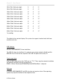
Power-On Self Test (POST)
Phoenix TrustedCore(tm) NB
Copyright 1985-2005 Phoenix Technologies Ltd.
All Rights Reserved
RT8-80708
CPU = 1 Processors Detected, Cores per Processor = 2
Intel(R) Core(TM)2 CPU
T5500 @ 1.66GHz
2039 System RAM Passed
2048 KB L2 Cache
System BIOS shadowed
Video BIOS shadowed
Fixed Disk 0: TOSHIBA MK1237GSX
ATAPI CD-ROM: Optiarc DVD RW AD-7530A
Mouse initialized
Current
BIOS-version
Press <F2> to enter SETUP, <F10> for Boot Menu, <F12> for Network Boot
Fig. 2.4: Boot sequence
Shortly after the switching on the notebook, a series of information will be displayed on the
screen. You may now press [F2] to start the BIOS setup of the notebook. As an alternative,
by pressing [F10], you can activate the boot menu. Find further information on this topic in
the “BIOS setup” chapter.
The system will now run a Power-On Self Test (POST). During this test, the main notebook
components are checked:
• processor
• memory
• interrupt controller
• keyboard
• inputs and outputs
• DMA controller, clock unit and video controller.
As part of this self test, the current hardware configuration is compared with the system’s
configuration data stored in the battery-based CMOS-RAM. In addition, all hardware components are routinely checked. If during the power-on self test a deviation from the current configuration and/or a hardware error is detected, the notebook will automatically ask you with a
message to start the Setup service program (➩ chapter 5).
2.4 Commissioning
Rocky III+ User Manual
Installing the Windows operating system
When you switch on the notebook for the first time, the Microsoft Windows XP start screen
will appear.
Follow the instructions on the screen.
Note
When switching on the notebook for the first time, the enclosed software will be installed
and configured. Since this process may not be interrupted, you should allow some time for
it and should leave the notebook connected to the line voltage via the mains adapter.
During installation, you may only reboot the notebook when requested to do so!
Adjusting screen brightness
You can adjust LCD display brightness to your needs with the following key combinations:
•
Increase brightness:
[Fn] + [F4]
•
Reduce brightness:
[Fn] + [F3]
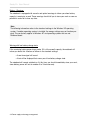
Switching off the notebook
There are different ways to switch off the notebook:
Shut down via the operating system
•
If required, save all input data on the hard disk drive or another data carrier.
•
With the mouse, click on the Windows start symbol in the lower left-hand corner
of your screen or press
•
Then, click on “Shut down” and, again, on the “Shut-down” symbol.
The system will now shut down.
Commissioning 2.5
Rocky III+ User Manual
Shut down via the power-on button
If required, save all input data on the hard disk drive or another data carrier.
Now, press the power-on button (➩ page 1.2 ) on the notebook for approx. 1 second. The
system will shut down in a controlled manner.
Depending on the energy settings of your operating system, pressing this button may also
put the notebook in idle state or standby mode. Find further information on this topic in the
“Power supply and energy management” chapter.
Shut down via the key combination
+
With key combination [Fn] + [F8], you may put the notebook either in idle state or standby
mode (➩ page 4.7). Find further information in the “Power supply und energy management”
chapter.
Shut down by closing the notebook
You may set your notebook’s energy management for the system to go into standby mode or
idle state when you close the notebook. Find further information on this topic on page 4.8.
Automatic shut down with an almost discharged battery
If the battery is almost fully discharged, the system will go to idle state as a standard. Find
further information on this topic in the “Power supply und energy management” chapter.
2.6 Commissioning
C H A P T E R 3
OperationalBasicsOperati
onalBasicsOperationalBas
icsOperationalBasicsOper
ationalBasicsOperational
BasicsOperationalBasics
OperationalBasicsOperati
onalBasicsOperationalBas
icsOperationalBasicsOper
ationalBasicsOperational
BasicsOperationalBasics
OperationalBasicsOperati
onalBasicsOperationalBas
icsOperationalBasicsOper
ationalBasicsOperational
BasicsOperationalBasics
OperationalBasicsOperati
onalBasicsOperationalBas
icsOperationalBasicsOper
ationalBasicsOperational
BasicsOperationalBasics
OperationalBasicsOperati
onalBasicsOperationalBas
icsOperationalBasicsOper
ationalBasicsOperational
Rocky III+ User Manual
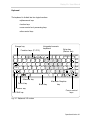
Keyboard
The keyboard is divided into four logical sections:
• alphanumeric keys
• function keys
• cursor-control and -processing keys
• other control keys
Escape key
Integrated numeric
keyboard
Enter key
(Return key)
Function keys (F1-F12)
Esc
F1
!
1
~
`
Q
Caps
Lock
F2
F3
F4
@
2
#
3
$
4
W
A
S
%
5
R
D
F6
^
6
T
F
F7
&
7
Y
G
F8
F10
*
8
7
U
H
F9
J
(
9
8
I
4
2
F12
)
0
9
O
5
K
1
F11
P
6
L
*
-
:
3
PrtScr Scroll Pause
SysRq Lock Break
_
-
+
=
{
[
}
]
X
Ctrl
C
V
B
N
Alt
M
<
,
0
|
\
>
.
AltGr
.
?
/
Ctrl
Del
Home
|
\
PgUp
PgDn
“
´
+
;
Z
Fn
E
F5
End
/
Ins
Alternate key
Control key
Function key
Left Shift key
Alternate-Graphics
Blank key
key
Cursor-control
keys
Fig. 3.1: Keyboard, US version
Operational basics 3.1
Rocky III+ User Manual
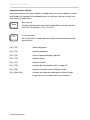
Integrated numeric keypad
Due to limited space, the numeric keypad for number entries and cursor settings on a notebook keyboard is integrated in the alphabetic keys. Use the Num Lock key to switch from
normal entry to number entry.
Num Lock key
Num
Activates and deactivates the numeric keypad. When activated, the Num
Lock LED is illuminated (➩ Fig. 1.3, pos. 3)
Fn (Function key)
Fn
The Fn key works in combination with another key and executes the following functions:
[Fn] + [F3]
reduces brightness
[Fn] + [F4]
increases brightness
[Fn] + [F5]
turns on keyboard backlight (optional)
[Fn] + [F6]
reduces volume
[Fn] + [F7]
increases volume
[Fn] + [F8]
activates idle state/standby mode (➩ page 4.7)
[Fn] + [F9]
switches to external screen/LCD/both screens
[Fn] + [Num,Pad]
activates the integrated number pad and then switches
to alphanumeric entry when the Fn key is pressed
3.2 Operational basics
Rocky III+ User Manual
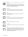
Alphanumeric keys
Caps Lock (lock key to enter capital letters)
By pressing this key once, the keyboard switches to capital-letter entry. At
the same time, the Caps Lock LED (➩ page 1.3) illuminates for control.
Press the key again, and the keyboard will switch to normal entry.
Shift
If you hold one of the two Shift keys while pressing another alphanumeric
key, you can enter a capital letter or the upper character in multiple key allocation. If you previously activated the switch to capital letters via the Caps
Lock key, you can enter small letters in combination with the Shift key.
Ctrl (Control) and Alt (Alternate)
Ctrl
Alt
In general, the Ctrl (Control) and Alt (Alternate) keys are only used in combination with another key, i.e., they are not used for entering characters. If you
hold down the Ctrl or Alt keys while pressing another key, you can execute
different functions, depending on the application. Find detailed information
on the program-specific functions of these keys in the respective software
documentation.
Alt Gr (Alternate Graphics):
Alt Gr
This key is used in combination with those keys that have another symbol
printed on them in the upper right-hand corner (➩ page 3.8)
Enter
This key is used to confirm an entry or command. On the DOS level as well
as in text-processing programs, the cursor is positioned in the first column of
the following line. The Enter key function is similar to the carriage return
function on a typewriter. Depending on the software used, the Enter key has
special functions which are explained in detail in the respective manuals.
Operational basics 3.3
Rocky III+ User Manual
Tabulator
The tabulator moves the cursor by a defined number of characters to a certain position to the right (tab stop) or vice versa in connection with the Shift
key. This key’s function also depends on the program currently installed. Find
further details in the respective documentation.
Function keys
F1
The top row of the keyboard houses 12 function keys (F1 through F12)
which have different functions, depending on the application program.
Escape
Esc
Within application programs, this key is frequently used to interrupt a program step or command.
Scroll Lock
Scroll
Lock
This key locks the cursor; the screen shot is moved by pressing the direction
keys. If this function is activated, the Scroll Lock LED is illuminated.
Pause
Pause
Break
This key stops the program. Press any key to continue.
Print Screen
PrtScr
SysRq
On the DOS level, the current screen contents are transmitted to the printer.
Insert
Ins
The function of this key depends on the application program used. In textprocessing programs, you can switch between the insert and the overwrite
mode by pressing this key. In the insert mode, the existing characters are
shifted when you enter new characters; in the overwrite mode, all new characters overwrite the existing characters.
3.4 Operational basics
Rocky III+ User Manual
Delete (Del) key
Del
This key deletes the character directly to the right of the cursor position.
Backspace
This key moves the cursor one position to the left while deleting one character.
Cursor keys
The cursor keys move the cursor in the
direction of the arrow, i.e., up, down,
to the left or to the right.
These keys move the cursor one page up or down.
PgDn
PgUp
Home
Home
This key moves the cursor to the first position in the line.
End
End
This key moves the cursor to the last position in the line.
Start key (Windows XP)
The start key is used to call the Windows start menu.
Start key (Windows Vista)
The start key is used to call the Windows start menu.
Menu key
The menu key calls the menu for the marked object.
Operational basics 3.5
Rocky III+ User Manual
Multiple key allocation
To write this character,
press the Num Lock key,
then press this key:
To enter this character,
hold down the Shift key,
then press this key:
(
8
To enter this character, only press
this key:
8
[
To enter this character, hold
down the Alt Gr key, then
press this key:
Fig. 3.6: Multiple key allocation
Using the touch pad
A touch pad’s functions are equivalent to those of a mouse. The touch pad is made up of a
touch field - the actual touch pad - and two other keys, just as with a conventional mouse.
The two keys to the left and right of the touch pad correspond to the left and right mouse
buttons.
Note
Even though this notebook has been designed for use under rugged conditions, you
should always keep the touch pad as clean and dry as possible.
In general, touch pads are sensitive to the touch. The touch pad integrated in this notebook is pressure-sensitive and has been designed for rugged use in extreme environments.
3.6 Operational basics
Rocky III+ User Manual
Touch pad functions
Moving the cursor:
With your finger, tip on the surface of the touch pad and
move your finger in the desired direction. It is irrelevant
on which part of the touch pad you start the movement.
One-time click:
Click the left mouse button or briefly tip on the touch pad
once.
Double click:
Briefly click the left mouse button twice or briefly tip on
the touch pad twice.
Click and hold:
Hold down the left mouse button while moving your finger
on the touch pad in the desired direction or briefly tip on
the touch pad twice and leave your finger on the touch
pad after the second click. Now, move your finger in the
respective direction.
Operational basics 3.7
Rocky III+ User Manual
TFT screen
As a standard, the notebook is equipped with a TFT color screen with a 1024 x 768-pixel
resolution.
Optionally, a 1400 x 1050-pixel resolution is available.
Note
For technical reasons, TFT screens are manufactured for specific resolutions. Optimal and
sharp-cut displays can only be guaranteed with the resolution the respective TFT screens
have been designed for. If you select a screen resolution other than the one defined in the
specifications, the result may be an unclear display.
Pixel error
In accordance with state-of-the-art production technology, screen displays with absolutely no
errors cannot be guaranteed. A small number of constantly bright or dark pixels may appear.
The maximum admissible number of faulty pixels is set down in the international norm ISO
13406-2 (Category II).
Pursuant to ISO 13406-2 (Category II), in a 1014 x 768-pixel resolution, a maximum of 4
pixels and an additional 5 sub-pixels may be defective, i.e., in total, 17 faulty sub-pixels. This
number corresponds to approx. 0.0007% of all sub-pixels.
3.8 Operational basics
Rocky III+ User Manual
Screen settings
Setting the resolution in Windows XP
In the “Resolution” field under Start -> (Settings) -> System control -> View -> Settings, you
can change the settings for the screen resolution.
Setting the resolution in Windows Vista
Under the Start -> (Settings) -> System control -> Display and adjustments -> Adjust screen
resolution, you can change the screen resolution.
Setting the font size in Windows XP
In the “Font size” field under Start -> (Settings) -> System control -> View -> Display and
designs, you can select between a larger and a smaller font size.
Working with several screens
With the multi-screen function in the Windows XP and Vista operating systems, you may
choose to divide the display of your Windows desktop onto two separate screens. When an
external analog screen (VGA output) or a digital screen (DVI connector) is connected, the
internal LCD screen and the connected external screen jointly assume the function of displaying the desktop.
Operational basics 3.9
Rocky III+ User Manual
Exchangeable hard disk drive
This notebook is equipped with an exchangeable 2.5” SATA hard disk drive with 120GB
capacity as a standard. This hard disk drive is installed in an exchangeable casing and additionally protected against dust and impact.
You may, at any time, replace this hard disk drive with a higher-capacity drive. To do so,
please contact your contract dealer.
HDD module
Fig. 3.10a: View with HDD module
Fig. 3.10b: Uninstalled HDD module
Find information on how to exchange the hard-drive modul from page 3.18 (➩ Installing and
uninstalling notebook modules) onwards.
3.10 Operational basics
Rocky III+ User Manual
Optical drive
As a standard, the front right-hand slot of your notebook houses the exchangeable DVD
drive which has been implemented as an IDE ATAPI drive. A DVD/CD-RW and DVD-RW
drive is also available.
Optionally, you may equip this slot with a secondary Lithium-Ion battery, a secondary hard
disk drive, a 3.5” diskette drive or a Dual Drive, i.e., a combination of DVD drive and 3.5” diskette drive.
The following formats are supported:
•
12cm CD/DVD
•
CD-ROM
•
Audio CD
•
CD-I
•
Video CD
Emergency-eject button
DVD eject button
DVD operation LED
Fig. 3.11: DVD drive
Operational basics 3.11
Rocky III+ User Manual
Inserting discs
Fig. 3.12a: DVD drive
Please follow these steps with your notebook switched on:
•
From the front, press the DVD eject button. The drive will slightly come forward.
•
Fully pull out the tray.
Fig. 3.12b: Inserting a disc
•
Insert a CD/DVD with the written side facing up on the tray and carefully press
down the CD/DVD in its center until it locks onto the cylinder.
•
Now, push the CD/DVD tray inwards until it locks.
•
The illuminated LED on the tray signals data access to the CD/DVD by the
notebook.
3.12 Operational basics
Rocky III+ User Manual
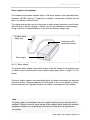
Opening the DVD drive via the emergency-eject opening
In casing of power loss or mechanical disturbances to the optical drive, you can remove the
CD/DVD manually.
Fig. 3.13: Emergency disk eject
Follow these steps to open the drive slot when your notebook is switched off or in case of a
disturbance:
•
Press a pen or wire (e.g., a paper clip) hard into the emergency-eject opening
so that the tray pops out easily.
•
Fully pull out the tray and remove the disc.
•
Press the tray until you it locks.
Operational basics 3.13
Rocky III+ User Manual
PC card and ExpressCard slots
As a standard, the notebook is equipped both with a Universal ExpressCard slot and a conventional PC card (PCMCIA card) slot.
Optionally, the notebook is available with two identical PC card slots.
1
3
2
Fig. 3.14a: PC card connector
1
Top slot: for inserting a PC card type II
2
Bottom slot: for inserting an ExpressCard (optional: PC card type II)
3
PC card eject button
Supported formats:
PCMCIA card module type 2
Fig. 3.14b: PC card formats
3.14 Operational basics
ExpressCard/54 module
ExpressCard/34 module
Rocky III+ User Manual
Inserting a PC card
With your notebook switched on, carefully insert the card in the slot with the correct side
facing up (see note on the card). As soon as you feel slight resistance, fully press the card
into the slot. The following signal informs you that the card has been recognized. Mind the
notes on the screen. It may be necessary to install driver software for the card to function
correctly. Find further information in the PC card manual.
Fig. 3.15: PCMCIA connector
Removing a PC card
Before removing the card manually, you must prepare the software in order to avoid disturbances. You do not have to follow these steps if you remove the card with your notebook
switched off.
1. Double click on the “Securely remove hardware” symbol in the task bar; the
“Securely remove hardware” dialog field will open.
2. Select the hardware to be removed.
3. Click “End.” The “Stop hardware device” dialog field will open.
4. Make sure that the device can be securely removed from the system.
5. Click “OK.” You will see a message telling you that the component can be securely removed.
6. Click “Close” to close the “Securely remove hardware” window.
Operational basics 3.15
Rocky III+ User Manual
Ejecting a PC card
Fig. 3.16a: PCMCIA connector
Slightly press the eject button inwards so that it pops out.
Fig. 3.16b: PCMCIA connection
Press the eject button hard inwards so that the card pops out a bit.
Fig. 3.16c: PCMCIA connection
Now, fully pull out the card.
3.16 Operational basics
Rocky III+ User Manual
Inserting an ExpressCard
Fig. 3.17: ExpressCard slot
Installing an ExpressCard
With the notebook switched on, carefully insert the ExpressCard in the bottom slot. As soon
as you feel slight resistance, fully press the card into the slot. Find further information in your
ExpressCard manual.
Removing an ExpressCard module
Since the ExpressCard sticks out from the slot when inserted, an eject button is not required.
In order to avoid problems, follow the steps described on page 3.15 (Removing a PC card) to
securely remove the hardware.
Then, pull the card from the slot. If you removed it properly, you will hear a high-pitched signal followed by a lower signal.
Attention
Some PC cards and ExpressCards heat up when used for a longer time, which may cause
errors or unstable operation of the respective notebook.
Do not remove the PC card if the notebook is in idle state or standby mode (➩ page 4.7).
Operational basics 3.17
Rocky III+ User Manual
Rocky III+ Benutzerhandbuch
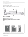
Installing and uninstalling notebook modules
This notebook is designed in a modular manner, which allows you to remove and exchange
the main components.
Primary battery
HDD module
DVD module, diskette drive or secondary battery
Fig. 3.18: Notebook modules
You may choose between several optional additions and modules for this notebook. Find further information on this topic in the Annex (➩ page A.4).
Preparing for module removal
Before starting to remove one or more modules, you should take the following preparatory
measures:
•
If the notebook is switched on, save your work and shut down the notebook properly.
•
Pull all the connections, including the power-supply cable.
•
Close the notebook and place it on a surface with the top part facing down.
Attention
When removing or exchanging modules, make sure that the notebook is neither in idle
state nor in standby mode (➩ page 4.7). Otherwise, it cannot be guaranteed that all components function properly.
3.18 Operational basics
Rocky III+ User Manual
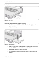
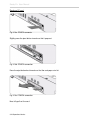
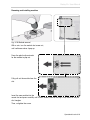
Removing and installing modules
Fig. 3.19: Module removal
With a coin, turn the module slot screw out,
until resilience makes it pop up.
Press the plastic clip outwards
for the module to pop out.
Fully pull out the module from the
slot.
Insert the new module into the
vacant slot and press carefully until it locks. Make sure that the clip is fully locked in the plastic triangles.
Then, re-tighten the screw.
Operational basics 3.19
Rocky III+ User Manual
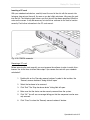
Removing the primary battery
For removing the battery, you only need to loosen the bottom screw. You may then directly
remove the module. Find further details on battery removal in the “Commissioning” chapter
(➩ Preparing the notebook for commissioning, page 2.1)
Fig. 3.20: Removing the primary battery
Note
You may only remove and/or exchange the modules discussed in this section. Removing
other casing parts, covers, screws, etc. will result in the notebook not sealing properly
and, hence, in warranty forfeiture. Opening or making changes to the notebook, including
memory extension, RTC battery exchange, etc., may exclusively be carried out by qualified persons at the respective repair centers.
3.20 Operational basics
C H A P T E R 4
Powersupplyandenergym
anagementPowerSupplya
ndEnergyManagementPo
werSupplyandEnergyMan
agementPowerSupplyand
EnergyManagementPowe
rSupplyandEnergyManag
ementPowerSupplyandE
nergyManagementPower
SupplyandEnergyManage
mentPowerSupplyandEn
ergyManagementPowerS
upplyandEnergyManage
mentPowerSupplyandEn
ergyManagementPowerS
upplyandEnergyManage
mentPowerSupplyandEn
ergyManagementPowerS
upplyandEnergyManage
mentPowerSupplyandEn
ergyManagementPowerS
upplyandEnergyManage
mentPowerSupplyandEn
ergyManagementPowerS
Rocky III+ User Manual
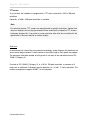
Power supply for the notebook
The notebook may be power supplied either via the mains adapter or the integrated battery.
Optionally, a DC/DC converter (➩ page 4.9) is available; it can be used to operate the notebook via a vehicle or similar battery.
This chapter also provides you with information on which energy resources to use the most
effectively and on battery charging. In addition, you will find information on battery-energy
saving as well as on notebook behavior in low and critical battery charge state.
Notebook powersupply plug
Green power LED
(operation indicator)
Power supply
Fig. 4.1: Mains adapter
The enclosed mains adapter automatically adjusts to the line voltage of the respective country. Make sure you have the correct country-specific power-plug version (➩ page C.1 in the
Annex).
The mains adapter supplies the connected notebook with power and charges the integrated
Lithium-Ion battery. The green operation LED illuminates as soon as the adapter is connected with the power line, regardless whether the adapter is connected with the notebook.
Note
For power supply to the notebook, only use original manufacturer parts provided for this
notebook. Otherwise you may cause damage to the notebook and/or externally connected
peripherals. Moreover, the manufacturer’s warranty will forfeit when you ignore these
instructions.
Power supply and energymanagement 4.1
Rocky III+ User Manual
Battery operation
The exchangeable Lithium-Ion battery is the notebook’s main power source when the mains
adapter is not connected. As a standard, the notebook is equipped both with a primary and a
real-time clock (RTC) battery.
You may choose to purchase an additional battery for longer, power-line-independent operation. This additional battery can be inserted in the DVD-drive slot.
RTC battery
The RTC (Real Time Clock) battery provides power to the integrated real-time clock and the
calendar even when the notebook is switched off and not connected with the mains adapter.
In addition, the RTC battery is responsible for maintaining the system settings in BIOS (➩
chapter 5). The RTC battery is also charged via the connected mains adapter. In order to
avoid losing system settings when the notebook is not used for a longer period of time, you
should connect the notebook with the mains adapter for a few hours at least once a month.
When commissioning the notebook, please make sure that date and time settings are correct; otherwise, you will need to adjust them. Find further information on this topic in chapter
5 (➩ BIOS setup).
Note
If required, the RTC battery installed in the notebook should only be replaced by authorized service staff, since it requires opening the notebook.
Primary battery
The notebook’s primary battery is made up of 9 Lithium-Ion cells. Before the battery is operated for the first time, the protective insulator must be removed (➩ page 2.1), and the battery must be fully charged.
Charging the battery
After connecting the notebook with the mains adapter and power line (➩ page 2.2), the battery will charge. The notebook can either be switched on or off during this process. The notebook’s charge indicator (➩ page 1.3) is illuminated until the battery is fully charged. Upon
completion of the charge process, the indicator LED will switch off. You may now use the
notebook without power-line supply.
As an accessory, you may also purchase an external charger to charge up to two batteries
outside of the notebook at the same time.
4.2 Power supply and energy management
Rocky III+ User Manual
Note
Please read and understand the instructions on battery maintenance and use as well as
the safety instructions at the beginning of this documentation.
Monitoring battery capacity
If the notebook operates with the battery, you may monitor the remaining battery energy as
follows in the Windows operating system:
Click on the “Battery” symbol in the task bar or, in Windows system control, on the “Energy”
symbol.
The following window will inform you on the charge status of the integrated battery/batteries.
Fig. 4.3: Battery charge status indicator
Power supply and energymanagement 4.3
Rocky III+ User Manual
Battery - Warnings
The notebook is equipped with acoustic and optical warnings to inform you when battery
capacity is coming to an end. These warnings should tell you to store your work as soon as
possible in order not to lose any data.
Note
The following information refers to the standard settings in the Windows XP operating
system. If another operating system is installed, the energy settings may not function properly. This particularly applies to Windows NT and operating systems that are not
Windows-based.
Warning with low battery-charge state
If the remaining battery power drops under 10% of the overall capacity, the notebook will
inform you about this situation as follows in the standard settings:
• A one-time signal will sound.
• A text will be displayed that warns you of low battery-charge state.
The notebook will remain switched on. At this time, you should immediately store your work,
since battery power will last for another 5 to 10 minutes only.
4.4 Power supply and energy management
Rocky III+ User Manual
Warning with critical battery-charge state
If the remaining battery power has reached a rest capacity of 5%, the notebook will automatically carry out the following measures in the standard settings:
• A one-time signal will sound.
• A text will be displayed that warns you of critical battery-charge state.
• The notebook will switch to idle state (➩ page 4.7).
If you have not done so, you must now connect the notebook with the mains adapter or
replace the low battery with a fully charged one.
If you switch on the notebook after the automatic shutdown, note that the battery will only
allow operation for a very short time. During the last minutes of battery power, the batterycharge state indicator will indicate this critical state.
Note
Battery performance and lifecycle depend on a number of factors, such as ambient temperature, age, number of charge and discharge cycles, etc. You may extend the battery’s
lifecycle by disconnecting the notebook from the electrical outlet at least once a month
and operating it in battery mode until the battery is fully discharged. Then, re-connect the
notebook with the mains adapter.
Power supply and energymanagement 4.5
Rocky III+ User Manual
Using the energy-saving modi
If you operate the notebook with a battery, you may choose to use different energy-saving
functions in order to extend operation time. Among other things, the duration of the battery
depends on the following factors:
•
processor type and CPU clock frequency
•
screen brightness
•
LCD switch-off
•
frequency and duration of access to the hard disk and optical drives
•
initial battery-charge status
•
usage intensity of connected and inserted additional devices, such as USB devices or ExpressCards that are powered via the battery.
Setting the energy-saving functions
Windows XP
Under Start -> System control -> Performance and maintenance -> Energy options, you can
set the notebook’s energy-saving functions.
Windows VISTA
Under Start symbol -> System control -> Mobile PC -> Energy options, you can set the notebook’s energy-saving functions.
You can configure the notebook so that, e.g., the hard disk drive or screen shuts down after
a defined period of time.
4.6 Power supply and energy management
Rocky III+ User Manual
In addition to the regular operation mode, in which different devices may be shut down, the
notebook has two different energy-saving levels: standby mode and idle state.
Standby mode
If you wish to briefly interrupt your work, you may switch off the notebook without closing the
application. In standby mode, the LCD screen is switched off, the hard disk drive shuts down
and the processor is clocked to a very low frequency. The notebook’s RAM continues to be
supplied with energy so that all information remains in the RAM. When you turn the notebook
back on, you can continue your work where you left off.
Idle state
When the idle state is activated, all data in the notebook’s RAM and the information on the
screen are stored on the hard disk drive. Thereafter, the notebook shuts down. Depending on
the open programs, this process may take a few seconds.
Note
Activating the standby mode will save energy, when you switch the notebook on and off
frequently.
You can also save energy by closing the screen when the keyboard is not in use or when
you briefly interrupt your work.
Manually activating standby mode and idle state
To activate these two modi, you have the following options:
•
key combination [Fn] + [F8]
•
press the power-on button for approx. 1 second
•
close the notebook
The notebook’s behavior when using either of the above options will depend on the energyoption settings for your notebook.
Power supply and energymanagement 4.7
Rocky III+ User Manual
The standard settings in Windows XP provide for the following configuration for the notebook:
•
press keys [Fn] + [F8]:
the notebook will switch to idle state
•
briefly press the power-on button: the notebook will shut down in a controlled
manner
•
close the notebook:
the notebook’s backlight will switch off; no
other measure will be implemented
Allocation to the individual functions may be defined and changed in the Windows XP operating system:
•
Click Start -> System control -> Energy options.
•
Select the “Extended” folder in the “Energy-option characteristics” window.
•
Define the required settings.
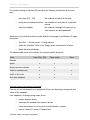
The following table shows all the options for customer-specific allocation:
Action
Press [Fn] + [F8]
Power switch
Close
Ignore
x
x
x
Request process selection
x
x
Switch to standby mode
x
x
x
Switch to idle state
x
x
x
Shut down notebook
x
x
Reaction
Important notes on the energy-saving modi
If you do not use the notebook for a long period of time, end the energy-saving mode and
switch off the notebook.
If the notebook is in energy-saving mode, do not
•
connect external devices
•
disconnect the notebook from external devices
•
switch the notebook on as long as the installed battery is empty
•
insert or remove PC cards or ExpressCards.
4.8 Power supply and energy management
Rocky III+ User Manual
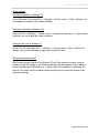
Vehicle adapter
Optionally, you may power supply the notebook via a tempered vehicle adapter that is available as an accessory. This adapter is responsible both for continuous power supply to the
notebook and for charging the battery/batteries in the notebook.
Vehicle adapter technical data
Input voltage:
16 - 34V
Output voltage:
19V +/- 0.2V
Output current:
4.2/4.75 A at <20 °C (68 °F)
Fig. 4.9: Tempered vehicle adapter DC/DC
Power supply and energymanagement 4.9
C H A P T E R 5
BIOSBIOSBIOSBIOSBIOS
BIOSBIOSBIOSBIOSBIOS
BIOSBIOSBIOSBIOSBIOS
BIOSBIOSBIOSBIOSBIOS
BIOSBIOSBIOSBIOSBIOS
BIOSBIOSBIOSBIOSBIOS
BIOSBIOSBIOSBIOSBIOS
BIOSBIOSBIOSBIOSBIOS
BIOSBIOSBIOSBIOSBIOS
BIOSBIOSBIOSBIOSBIOS
BIOSBIOSBIOSBIOSBIOS
BIOSBIOSBIOSBIOSBIOS
BIOSBIOSBIOSBIOSBIOS
BIOSBIOSBIOSBIOSBIOS
BIOSBIOSBIOSBIOSBIOS
BIOSBIOSBIOSBIOSBIOS
BIOSBIOSBIOSBIOSBIOS
BIOSBIOSBIOSBIOSBIOS
BIOSBIOSBIOSBIOSBIOS
BIOSBIOSBIOSBIOSBIOS
BIOSBIOSBIOSBIOSBIOS
BIOSBIOSBIOSBIOSBIOS
BIOSBIOSBIOSBIOSBIOS
BIOSBIOSBIOSBIOSBIOS
Rocky III+ User Manual
BIOS setup
The BIOS setup serves to set and change important system information, such as time, date,
hard disk drive type, DVD drive, passwords, interfaces, etc. All parameters are saved in the
CMOS-RAM and may be changed upon demand. The CMOS-RAM is power supplied via the
RTC battery so that these settings are maintained, even if the notebook is switched off and
disconnected from the power-supply unit.
The settings may only be defined via the keyboard. When you first receive the notebook, the
standard settings will have been defined.
Starting the BIOS setup
•
Start the notebook (switch off/on or reboot).
•
Wait for the following information to be displayed in the bottom-most line on the
screen:
“Press <F2> to enter SETUP, <F10> for Boot Menu, <F12> for Network Boot.”
•
Now, press function key [F2] to go to Setup.
•
If a password has been installed, enter it and press Enter.
BIOS setup menu
The BIOS setup is made up of the following menus:
Main:
system settings for time, date, hard disk and other drives
Advanced:
parameter settings for interfaces, etc.
Security:
creation of passwords and safety-function settings
Boot:
configuration of the boot order
Exit:
end the BIOS setup
BIOS setup 5.1
Rocky III+ User Manual
Using the menu and changing the settings
Key command
Function description
[F1]
call the Help menu
Cursor keys left/right
select the respective menu
Cursor keys up/down
select the individual sub-items
[F5] bzw. [+]
switch to the previous value
[F6) bzw. [ - ]
switch to the next value
ENTER
call a sub-menu, if available
[F9]
upload the system’s standard settings
[F10]
save the changes and leave the Setup
ESC
leave the Setup
Note
Please note that in the Setup mode, the system uses the English keyboard definition, even
if a German keyboard layout is available.
5.2 BIOS setup
Rocky III+ User Manual
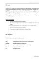
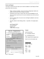
Main setup
Fig. 5.3: BIOS setup
System-Time / System-Date
Use these two parameters to set the current system date and time.
The system automatically detects and uses the following parameters:
Legacy diskette A: displays size and format of the installed diskette drive
IDE Channel 0 Master: displays type of installed HDD
IDE Channel 0 Slave: N/A
IDE Channel 1 Master: displays the installed optical drive
IDE Channel 1 Slave: N/A
System memory: displays size of system memory
Extended memory: displays size of extended memory
BIOS setup 5.3
Rocky III+ User Manual
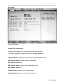
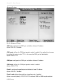
Advanced setup
Fig. 5.4: Advanced setup
Legacy USB support: enables or disables functions of all USB interfaces.
Options: enabled (default), disabled
Summary screen: displays system configuration when booting.
Options: disabled (default), enabled
Quick boot mode: enables or disables the fast-boot mode in which certain tests are skipped.
Options: enabled (default), disabled
Extended Memory Testing: determines the type of tests to be performed on the extended
memory (> 1MB).
Options: none (default), normal, Just zero it
IGD-boot type: selects the screen to display the video signal during booting.
Options: VBIOS Default, CRT, LFP,CRT+LFP, TV, LFP+SDVO, EFP, TV-SDVO,
CRT+LFP+SDVO, CRT+EFP
PS/2 mouse: configures the PS/2 connector used for the touch pad and any external PS/2
mouse connected.
Options: Disabled: disables any PS/2 mouse, but leaves IRQ12 open for manual allocation of
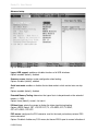
5.4 BIOS setup
Rocky III+ User Manual
other devices.
Enabled: enables the PS/2 mouse connector, regardless whether or not a mouse is connected.
Auto Detect: enables the PS/2 mouse only if available.
PCI Express Root Port 1: configures the Express Port.
Options: enabled (default), auto, disabled
Enabled: port is always enabled.
Disabled: port is always disabled.
Auto: enables the port only enabled if a card is found.
Note: If Root Port 1 is disabled, Root Ports 2 through 4 will also be disabled.
USB Device 29, Function 7: enables or disables USB 2.0 functionality.
Options: enabled (default), disabled
Disabled: throttles data-transfer speed for USB1 compatibility. This measure is required, e.g.,
in the event of problems with peripherals with very long USB cables. Throttling data-transfer
speed could solve this problem.
Passive Cooling Trip Point: sets a temperature threshold for the CPU to be throttled to
avoid overheating.
Options: settings from 15 to 119 °C (59 to 246 °F) in steps of 8 °C; default = 79 °C (174 °F)
Processor Power Management:
Options: Disable, GV3 only, C-States, Enable (default).
SIO SMC227 Configuration: configures all National 393 SIO devices. Press Enter to go to
another Advanced Setup in which you can also define settings (see next page).
BIOS setup 5.5
Rocky III+ User Manual
Advanced-2 setup
Fig. 5.6: Advanced-2 Setup
COM1 port: configures the COM1 port and defines its base I/O address.
Options: 3F8-IRQ 4, disabled
COM1 mode: defines the COM1 port operation mode, if enabled. If an optional touch screen
is installed, this value is set to TTL1. In this case, the COM1 port will be disabled.
Options: RS232, TTL1
COM2 port: configures the COM2 port and defines its base I/O address.
COM2 mode: defines the COM2 port operation mode, if enabled.
Options: RS232, TTL2
Printer1: configures the parallel port and defines its base I/O address.
Options: 378-IRQ 7, disabled
Printer1 mode: defines the parallel port operation mode, if enabled.
Options: standard (default), ECP, EPP. If ECP is defined, DMA1 or DMA3 may be selected.
5.6 BIOS setup
Rocky III+ User Manual
Security setup
Fig. 5.7: Security setup
Processor Serial Number: enables or disables detection of the processor serial number.
System must be rebooted for changes to take effect.
Options: disabled, enabled
Set Supervisor Password: defines a password for access to the system’s BIOS (setup utility). Press Enter to display a dialog window in which to enter the password.
Set User Password: used to create a user password. Press Enter to display a dialog window in which to enter the password.
Note
If a password has been defined, memorize it or write it down in a secret place. If you forgot the password, the password can only be deleted by a service technician. This service
will not be covered by general warranty.
BIOS setup 5.7
Rocky III+ User Manual
Fixed Disk Boot Sector: enables or disables the write protection for the hard disk drive
boot sector to protect it against viruses. Requires a password for the FDISK function or a format commande to be executed when booting.
Options: normal (default), write protect
Diskette access: enables access to diskette drives.
Password on boot: enables or disables the command for password entry. Ths function
requires prior creation of the supervisor password.
Options: disabled (default), enabled
USB interface: enables or disables the USB functions available in the device.
Options: enabled (default), disabled
AC97 audio interface: enables or disables the integrated AC97 audio card.
Options: auto (default), disabled
Auto: AC97 will be enabled, if available.
Disabled: AC97 audio card will be disabled, regardless of its availability.
AC97 modem interface: enables or disables the integrated AC97 modem.
Options: auto (default), disabled
Auto: AC97 modem will be enabled, if available.
Disabled: AC97 modem will be disabled, regardless of its availability.
Cardbus/1394 interface: enables or disables the CardBus and the 1394 interface.
Options: auto (default), disabled
RF security control: press Enter to individually enable or disable the functions for WLAN,
GPRS, GPS and Bluetooth.
5.8 BIOS setup
Rocky III+ User Manual
Boot setup
Fig. 5.9: Boot setup
Boot priority order: defines the order of the devices that are accessed during system boot.
Excluded from boot order: defines the devices to be excluded from boot order.
BIOS setup 5.9
Rocky III+ User Manual
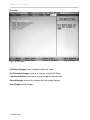
Exit setup
Fig. 5.10: Exit setup
Exit Saving Changes: saves changes and ends the Setup.
Exit Discarding Changes: discards all changes and ends the Setup.
Load Setup Defaults: loads default settings (except for date and time).
Discard Changes: discards the changes and loads original settings.
Save Changes: saves changes.
5.10 BIOS setup
C H A P T E R 6
DriverSoftwareDriverSoft
wareDriverSoftwareDriver
SoftwareDriverSoftwareD
riverSoftwareDriverSoftw
areDriverSoftwareDriverS
oftwareDriverSoftwareDri
verSoftwareDriverSoftwar
eDriverSoftwareDriverSof
twareDriverSoftwareDrive
rSoftwareDriverSoftware
DriverSoftwareDriverSoft
wareDriverSoftwareDriver
SoftwareDriverSoftwareD
riverSoftwareDriverSoftw
areDriverSoftwareDriverS
oftwareDriverSoftwareDri
verSoftwareDriverSoftwar
eDriverSoftwareDriverSof
twareDriverSoftwareDrive
rSoftwareDriverSoftware
DriverSoftwareDriverSoft
wareDriverSoftwareDriver
SoftwareDriverSoftwareD
riverSoftwareDriverSoftw
Rocky III+ User Manual
DRIVER SOFTWARE
Note: Most device drivers are available in Windows 98/2000/ME/XP. Only if the default driver
does not work properly will you need to install it from the enclosed CD.
The utility CD includes most drivers for the devices installed in the notebook. Contact your
dealer if any driver is missing or does not work properly upon installation. Please read the
readme file on the driver CD for your notebook before starting to install new drivers.
Chip set Windows WINXP/WIN2000/WIN98SE/ME driver installation:
Select the directory RK8EX-RF8EX-DR8EX\Drivers\Chipset\2kXpVista..., then start
infinst_autol.exe and follow the prompt to complete the installation.
VGA driver installation for Windows 98SE/2000/ME/XP:
Insert the driver CD into the DVD drive. Select the directory RK8EX-RF8EXDR8EX\Drivers\VGA\,Intel_945GM\2kXP32 and start win2k_xp1429.exe. Follow the prompt to
complete the installation. After rebooting the system, you can set the correct color depth and
resolution under “Properties of display” under Systems control.
Standard resolution:
1024 x 768 pixels
Settings for SXGA+ screen (optional):
1400 x 1050 pixels
The following table lists the setting options for the internal display (LCD) and external screen
(CRT) or the external digital screen via the DVI output.
Performance of the VGA utility display
Resolution & color depth
LCD
RGB
LCD + RGB
640x 480x 16-bit color depth
O
O
O
640x 480x 24-bit color depth
O
O
O
640x 480x 32-bit color depth
O
O
O
800x 600x 64K color depth
O
O
O
800x 600x 24-bit color depth
O
O
O
800x 600x 32-bit color depth
O
O
O
Driver software 6.1
Rocky III+ User Manual
1024x 768x 16-bit color depth
O
O
O
1024x 768x 24-bit color depth
O
O
O
1280x 1024x 16-bit color depth
O*
O
O*
1280x 1024x 24-bit color depth
O*
O
O*
1280x 1024x 32-bit color depth
O*
O
O*
1600x 1200x 16-bit color depth
O*
O
O*
1600x 1200x 24-bit color depth
O*
O
O*
1600x 1200x 32-bit color depth
O*
O
O*
2048x 1536x 16-bit color depth
O*
O
O*
2048x 1536x 24-bit color depth
O*
O
O*
2048x 1536x 32-bit color depth
O*
O
O*
* by scrolling
This table lists the standard displays. The system also supports standard modi with lower
resolution and color.
USB 2.0 driver
Windows 98SE/2000/ME/XP driver installation:
The USB 2.0 drivers for the Rocky III+ notebook must only be installed in Win2K and Win
98SE/ME. You will find the files required for the USB 2.0 update on the utility CD.
Touch screen driver
Enter the BIOS setup and set the COM1 port as “TTL1.” Then, stop the automatic installation
and manually install the driver by starting the file
RK8EX...\Drivers\Touchscreen\DP9000\2kXpVista3264\PentMount...\setup.exe.
DVD drive
In Windows 98SE/2000/ME/XP, the DVD drive does not require a driver. Other operating
systems may require installation of the respective driver.
6.2 Driver software
Rocky III+ User Manual
PCMCIA driver in Windows 98SE/2000/ME/XP
The driver is automatically installed in Windows, except for Windows 98SE where you will
need to manually install it. After Windows 98SE has detected a new PCMCIA card, the driver
must be updated from the CD: click Start -> System control -> System -> Device manager
-> PCMCIA adapter -> Card bus.
Audio driver in Windows 98SE/2000/ME/XP
Insert the driver CD into the DVD drive. Click WDM_A400.exe in the directory
RK8EX...\Drivers\Audio\2kxp_3264. The installation wizard will guide you through installation.
LAN driver
Drivers for the 98SE/2000/ME/XP operating systems are available in the directory
RK8EX..\Drivers\PCIe_1GLAN. For installation, start the device manager in your operating
system, select the network adapter and the respective card for the correct operating system.
Then, click “Driver update.” Follow the prompt on the screen up to installation completion.
Mini PCI-E Intel 3945ABG WLAN driver
Insert the driver CD into the DVD drive. Click v11.1.0.5_xp32.exe in the directory
RK8EX...\Drivers\PCIe_Intel WLAN\2kXp32 and follow the prompt to complete the installation.
Fax-card/modem-card drivers
Insert the driver CD into the DVD drive. Click setup.exe in the directory
RK8EX...\Drivers\MDC\mdc_w2kxp and follow the prompt to complete the installation.
Bluetooth driver
Insert the driver CD into the DVD drive. Click setup.exe in the directory
RK8EX...\Drivers\BLU-BC4\2kxp\BlueSoleil_(Standard) and follow the prompt to complete
the installation.
Driver software 6.3
A N N E X
AnnexAnnexAnnexAnne
xAnnexAnnexAnnexAnn
exAnnexAnnexAnnexAn
nexAnnexAnnexAnnexA
nnexAnnexAnnexAnnex
AnnexAnnexAnnexAnne
xAnnexAnnexAnnexAnn
exAnnexAnnexAnnexAn
nexAnnexAnnexAnnexA
nnexAnnexAnnexAnnex
AnnexAnnexAnnexAnne
xAnnexAnnexAnnexAnn
exAnnexAnnexAnnexAn
nexAnnexAnnexAnnexA
nnexAnnexAnnexAnnex
AnnexAnnexAnnexAnne
xAnnexAnnexAnnexAnn
exAnnexAnnexAnnexAn
nexAnnexAnnexAnnexA
nnexAnnexAnnexAnnex
AnnexAnnexAnnexAnne
xAnnexAnnexAnnexAnn
exAnnexAnnexAnnexAn
nexAnnexAnnexAnnexA
Rocky III+ User Manual
Technical data
Processor
Intel® Core 2 Duo Mobile T5500, 2MB shared Level2 Cache, 1.66GHz, FSB 667MHz
Memory
1GB - 4GB DDR2 RAM
Hard disk drive
120GB, Serial ATA, exchangeable
Diskette drive (not contained in scope of delivery)
3.5” floppy drive, connectable externally via the parallel port as a single drive
Optical drive
DVD drive
LCD screen
15.1” TFT active matrix display, 1024 x 768 pixels, 16.7 m colors
or, optionally, 15.1” TFT active matrix display, 1400 x 1050 pixels, 16.7 m colors
Graphic card
224MB SMA (max.) Intel Graphics Media Accelerator 950 (GMA 950), Integrated 256-bit,
400MHz Core 3D/2D, Dynamic Video Memory Technology (DVMT)
Optionally: Nvidia Geforce 7600 Go or Nvidia Geforce 8400 Go
Keyboard
integrated German keyboard with integrated numeric keypad
Annex A.1
Rocky III+ User Manual
Pointing device
Touch pad, PS/2 pressure-sensitive (resistive), external mouse can be connected
Sound card
AC97 sound, 16-bit, stereo loudspeakers
Interfaces
2 x USB 2.0 (on the back for mouse/keyboard)
1 x parallel on Sub-D, 25-pole
2 x RS-232 on Sub-D, 9-pole
2 x IEEE 1394 (FireWire)
1 x PS/2
1 x 120-pin docking connector
1 x VGA (on Sub-D, 3 lines, 15-pole)
1 x DVI-D on DVI-I with USB (in Dual-Link version for remote function)
3 x audio: micro-in, speaker-out, line-out
1 x PC card-slot type II
1 x ExpressCard (PCIe)
1 x LAN Ethernet 10/100/1000 Mbit on RJ45
1 x DC-in MIL
Battery
Integrated, rechargeable Lithium-Ion battery, capacity: 7200mAh,
secondary Lithium-Ion battery, exchangeable, can be integrated in DVD-drive slot (operating
time: 140 or 280 minutes), not contained in scope of delivery
Power Supply
Secondary voltage:
19V DC
Operating voltage:
100 to 250V, 50 to 400Hz
External DC/DC power-supply unit, VG-compliant pursuant to VG 96916 part 5
AC/DC power-supply unit
System heater
-21 °C, max. heating time until operational: 10 minutes
-31 °C, max. heating time until operational: 26 minutes (extended temperature range)
A.2 Annex
Rocky III+ User Manual
Power consumption
Operating: 30W, max. (heating operation): 68W
Measurements and weight
Width x Height x Depth
340 x 64 x 284 mm
(wihout rubber bumpers)
Weight
5.5kg incl. battery and optical device
Casing
magnesium/aluminum
Certifications
IP55, MIL-STD 810F, MIL 461
Environmential specifications
Results of the US Military Standard MIL-STD-810 F/EMI/RFI
Height above sea level
(Method 500.4 Procedure I, II)
4570m (operating) or 12180m*
12180m (storage)
Ambient temperature
(Method 501.4, Procedure I, II)
(Method 502.4, Procedure I, II)
-20 to +50 °C (-4 to +122 °F) (operating)
-40 to +70 °C (-40 to +159 °F) (storage)
Temperature shock
(Method 503.4, Procedure I)
-40 to +70 °C (-40 to +159 °F) (storage)
(operating N/A)
Solar radiation
(Method 505.4, Procedure I)
Diumal Cycle A1, worldwide deployment
(operating and storage)
Rain protection
(Method 506.4, Procedure I)
276kPa; 0.5 - 4.5 mm diameter (storage)
(operating n/a)
Humidity
(Method 507.4, Procedure I)
95% (storage)
(operating N/A)
Salt fog
(Method 509.4, Procedure I)
5%; 35 °C (95 °F) (storage)
(operating N/A)
Explosive atmosphere
(Method 511.4, Procedure I)
passed
(operating and storage)
Annex A.3
Rocky III+ User Manual
Vibration
(Method 514.5 Category 5)
(Method 514.5 Category 14, Prozedur I)
(Method 514.5 Category 20, Prozedur I)
Shock
(Method 516.5, Procedure I)
Tracked Vehicle Vibration
Helicopter Vibration OH58A/C
Comp. Wheeled Vehicle Vibration
(operating and storage)
40g; 11ms
(operating and storage)
* only with special HDD casing (not contained in scope of delivery)
Options
•
Removable Flash Disk SATA
•
LCD screen with SXGA+ (1400x1050) resolution
•
NVIDIA GeForce 7600Go Graphics Processor Unit, 256MB high speed DDRII
memory dedicated, alternative: NVIDIA GeForce 8400Go
•
Touch screen resistive, sunlight readable
•
Dual Drive (3-spindel): DVD+FDD internal simultaneously
•
CD-RW/DVD-RW drive
•
56K fax/modem MDC
•
2nd LAN card 10/100/1000 MBit
•
4x RS232 external interfaces
•
Fiberoptic LAN 100/1000 Mbit
•
WLAN card (Intel Pro Wireless 3945ABG 802.11a/b/g)
•
GPRS/GSM card (Siemens MC75)
•
GPS module (SIRF STAR III)
•
Bluetooth module v2.0 class 1/2
•
PCMCIA 2 x type II or 1 x type III
•
Internal CAN BUS card
•
Integrated chip-card reader
•
Internal vehicle adapter (direct DC 12-32V input)
•
Backlight for keyboard
A.4 Annex
Rocky III+ User Manual
•
Extended temperature range up to -30 °C (86 °F) only wiht released HDDs, i.e.,
Hitachi Endurastar, or with additional heater elements
•
Separte mass conduct and/or isolated mass concept for vehicle installation
•
Version wiht military round connectors
•
MIL-STD 461E certification Ground Navy / Ground Army
•
Zone 0 / SDIP 27 Class A
•
Zone 1 / SDIP 27 Class B
Accessories
•
external 3.5” diskette drive
•
secondary battery (11.1V/7200mAh Lithium-Ion battery) > 4 h operating time
(exchangeable with DVD drive)
•
secondary hard disk drive (exchangeable with DVD drive)
•
keyboard protection against dirt, for standard keyboard without backlight
•
PC card cover (protection of the PC card connector)
•
external vehicle adapter (DC 12-32V input)
•
battery charger for primary and secondary batteries
•
docking station DockUnder with PCI slot, VGA/DVI interface and internal vehicle
adapter
Annex A.5
Rocky III+ User Manual
Error messages and troubleshooting
The notebook does not start.
•
Please make sure the notebook is properly connected with a power source and
switched on. Check whether the line indicator of the mains adapter is active.
•
Make sure the battery is properly installed and charged.
•
If the notebook is connected with a multiple electrical outlet or an uninterruptible
power supply (UPS), make sure that the multiple electrical outlet or the UPS is
connected with a power source and switched on.
•
If you are using an external screen, make sure it is connected with a power
source and switched on. Make sure the regulators for brightness and contrast
are correctly set. Find further information on this topic in the manual for the indicator device.
•
Disconnect the power-supply cable and remove the battery. Wait for 3 to 5 minutes. Then, re-insert the battery, re-connect the power-supply unit and press the
power-on button to switch on the notebook.
A BIOS error occurs when switching on the notebook.
Follow these steps when the message “Press <F1 > to resume, <F2> to setup” appears in
the bottom section of the screen:
1. Press [F2].
The BIOS setup screen will be displayed. If not, reboot the notebook and press
[F2] a number of times as soon as text is displayed on the screen.
2. Set the date (month/day/year). Press [Enter].
3. Set the time (hour: minute: second). Press [Enter[.
4. Select “Exit” in the Setup menu, then go to “Exit saving changes.”
The notebook will now reboot. Please contact your Service Center should this error occur
frequently.
Annex B.1
Rocky III+ User Manual
There is no display on the screen, even though the green operation indicator is illuminated.
Follow these steps:
1. Press the power-on button for more than 4 seconds and check whether the
power indicator extinguishes. Then, switch the notebook back on.
2. If there is still no display on the screen, disconnect the power-supply unity cable,
remove the battery and wait for approx. 1 minute. Then, re-insert the battery, reconnect the power-supply unit and switch the notebook back on.
The notebook or software no longer reacts.
•
If the notebook no longer reacts when carrying out a software application, press
key combination [Alt] + [F4] to close the application window.
•
If key combination [Alt] + [F4] does not work, press key combination [Ctrl] + [Alt]
+ [Del] to call the task manager. Then, click “Shut down” in the menu and re-boot
the system.
•
If the notebook does not react to any of the above measures, hold the power-on
button until the notebook shuts down.
•
Disconnect the power-supply cable and remove the battery.
Attention
When you switch the notebook off with key combination [Ctrl] + [Alt] + [Del] or with the
power-on button, you may lose unsaved data.
•
Try to re-install the software.
•
Contact the software manufacturer or Technical Support.
B.2 Annex
Rocky III+ User Manual
Service and Support
In the event of repair works that require you to send the notebook to roda Computer GmbH,
please follow these instructions:
•
Before sending the notebook, clarify with the Service Department whether the
problem can be solved without sending the notebook.
•
Download the service form for repair works from the roda homepage. You will
find this document in pdf format in the service download area at www.roda-computer.com.
•
Enter all required data in the service form, including the notebook’s serial number (➩ page 1.7).
•
Send the notebook to the following address - if possible, in the original packaging:
roda Computer GmbH
Service-Abteilung
Bredenhop 20
32609 Hüllhorst Germany
Contact:
roda Service-Center
Fon: +49 (0)5744-944-470
Fax: +49 (0)5744-944-475
E-Mail: [email protected]
Internet: www.roda-computer.com
Business hours:
Monday - Thursday
08:30 - 12:30
13:00 - 16:30
Friday
08:30 - 12:30
13:00 - 15:00
Fig. E.1: Service form
Annex B.3
Rocky III+ User Manual
Overview of the power supply connectors for different countries
Version
Country/region
Technical data
Europe
220V, 50Hz, 6A
Switzerland
220V, 50Hz, 6A
Great Britain
240V, 50Hz, 6A
Australia
240V, 50Hz, 6A
North America
240V, 60Hz,10A
North America
120V, 60Hz, 7A
Table C.1: International line-cable connectors
B.4 Annex
Rocky III+ User Manual
INDEX
Boot setup - 5.9
Bottom view - 1.7
AC97 audio interface - 5.8
Brightness, set - 3.2
AC97 modem interface - 5.8
Caps key - 3.3
Accessories - A.5
Caps Lock key - 1.3, 3.3
Alt Gr key - 3.3
Card formats - 3.14
Alt key - 3.3
Cardbus/1394 interface - 5.8
Ambient temperature - A.3
CD tray - 3.12
Audio driver - 6.3
Certifications - A.3
Battery - 4.2
Chipset driver - 6.1
Battery, capacity - 4.3
COM1 mode - 5.6
Battery, capacity monitoring - 4.3
COM1 port - 5.6
Battery, charge - 4.2
COM2 mode - 5.6
Battery, charge status indicator - 4.3
COM2 port - 5.6
Battery, critical charge status - 4.5
Commissioning - 2.1
Battery, discharged - 4.3
Connectors - 1.2
Battery, maintenance instructions Seitenangabe
Control key - 3.3
Battery, operation - 4.2
Battery, remove - 3.20
Battery, warnings - 4.4
Battery, low charge status - 4.4
BIOS - 5.1
BIOS, error - B.1
BIOS setup, menu - 5.1, 5.2
BIOS setup, start - 5.1
BIOS version - 1.7, 2.4
Bluetooth driver - 6.3
Boot priority order - 5.9
Control keys, other - 3.4
Ctrl key - 3.3
Declaration of conformity - a.2
Default settings - 5.10
Device-type label - 1.7
Disk emergency reject - 3.13
Diskette access - 5.8
Disks, insert - 3.12
Docking station - 1.6
Docking station, connector - 1.6
Driver software - 6.1
DVD, drive - 1.5, 3.11
Index register i.1
Rocky III+ User Manual
DVD, eject button - 1.5, 3.12
Extended memory testing - 5.4
DVD, emergency-eject slot - 1.5
Fax/modem driver - 6.3
DVD, in-use indicator - 1.5
FireWire 1394 - 1.4, A.2
DVD, tray - 3.12
First serial interface - 1.6
DVD-RW drive - 3.11
Fixed disk boot sector - 5.8
DVI connector - 1.6, 3.9
Font size, set - 3.9
Emergency-eject opening - 3.13
Front view - 1.2
Energy, options - 4.6
Function keys - 3.4
Energy, supply - 4.1
Hard disk drive - 3.10
Energy-saving functions, set - 4.6
Hard disk drive, module - 3.10, 3.18
Energy-saving modi - 4.5
Hard disk drive, exchangeable - 3.10
Enter key - 3.3
HDD-in-use indicator - 1.3
Environment specifications - A.3
Heating - 2.3
Error messages - B.1
Height above sea level - A.3
Error messages and troubleshooting - B.1
Humidity - A.3
Esc key - 3.4
Idle state - 4.7
Escape key - 3.4
Idle state, activate - 3.2, 4.7
Ethernet RJ45 - 1.4
IGD boot type - 5.4
Exchangeable hard disk drive - 1.5
Integrated numeric keypad - 3.2
Excluded from boot order - 5.9
Interfaces - Seitenangabe
Exit Discarding Changes - 5.10
Interface, parallel - 1.6, 5.6
Exit Saving Changes - 5.10
International line-cable connectors - C.1
Exit setup - 5.9 - 5.10
Key combinations - 3.2
ExpressCard - 3.14
Keyboard - 3.1
ExpressCard, formats - 3.14
Keypad, alphanumeric - 3.1
Express Card, install - 3.17
Keypad, numeric - 3.1, 3.2
ExpressCard, remove - 3.17
Keys, alphanumeric - 3.3
ExpressCard, slot - 3.14
LAN driver - 6.3
Extended memory - 5.3
LCD brightness - 3.2
i.2 Index register
Rocky III+ User Manual
LCD monitor - 1.2, 3.8
Numeric keypad - 3.1, 3.2
LCD screen - 3.8
Operating system
LED indicators - 1.3
Operation system, install - 2.5
Left-side view - 1.4
Operational basics - Seitenangabe
Legacy diskette A - 5.3
Optical drive - 3.11
Legacy USB port - 5.4
Options - A.4
Line adapter - 4.1
Options and accessories - A.4
Line cable, connect - 2.2
Passive Cooling Trip Point - 5.5
Line-in - 1.4
Password - 5.7
Line-cable, connectors - 4.1, C.1
Password on boot - 5.8
Line-out - 1.4
PC card - 3.14
Loudspeaker - 1.2
PC card, eject button - 3.14
Main setup - 5.3
PC card, formats - 3.14
Microphone input - 1.4
PC card, insert - 3.15
Military connector - 1.6
PC card, install - 3.15
Military standard - A.3
PC card, remove - 3.15
Mini PCI-E driver - 6.3
PC card, slot - 3.14
Mini PCI-E WLAN driver - 6.3
PCI Express Root port 1 - 5.5
Modem, connector - 1.4
PCMCIA card - 3.14
Modem, driver - 6.3
PCMCIA card, indicator - 1.3
Module - 3.18
PCMCIA, driver - 6.3
Module, remove and install - 3.19
Pixel error - 3.8
Module-slot screw - 1.7
POST - 2.4
Multi-monitor function - 3.9
Power indicator - 1.3
Multiple key allocation - 3.6
Power-on button - 1.2, 2.3
Notebook, connect - 2.2
Power supply - 4.1
Notebook, open - 2.3
Power-supply unit - 2.2
Notebook, module - 3.18
Power-On Self Test (POST) - 2.4
Num Lock indicator - 1.3, 3.2
Preheating - 2.3
Index register i.3
Rocky III+ User Manual
Primary battery - 3.20
Shift key - 3.3
Primary battery, remove - 3.20
Shock - A.3
Printer 1 mode - 5.6
Shut down - 2.6
Processor, power management - 5.5
Shut down, automatic - 2.6
Processor, serial number - 5.7
SIO SMC227 configuration - 5.5
Protective insulator - 2.1
Standby mode - 4.7
PS/2, connector - 1.4, 5.4
Standby mode, manual activation - 4.7
PS/2, mouse - 5.4
Strg key - 3.3
QuickBoot mode - 5.4
Summary screen - 5.4
Rain protection - A.3
Supervisor password - 5.7
Rear view - 1.6
Supervisor password, set - 5.7
Resolution, set - 3.9
Switch off notebook - 2.6
RF security control - 5.8
Switch on notebook - 2.3
Right-side view - 1.5
System memory - 5.3
Salt contents - A.3
System time - 5.3
Screen, resolution - 3.8
Tabulator key - 3.4
Screen, settings - 3.9
Technical data - A.1
Scroll Lock - 3.4
TFT screen - 3.8
Scroll Lock, indicator - 1.3, 3.4
Time, set - 5.3
Scroll Lock, key - 3.4
Touch pad - 3.6
Secondary battery, charge - 4.5
Touch pad, key - 1.2
Security setup - 5.7
Touch screen, driver - 6.2
Self test - 2.4
USB 2.0, connector - 1.4, 1.6
Serial number - 1.7
USB 2.0, driver - 6.2
Setup - 5.1
USB, device 29 - 5.5
Setup defaults, load - 5.10
USB, driver - 6.2
Setup, advanced - 5.4, 5.6
USB, interface - 5.8
Setup, default settings - 5.10
User password, set - 5.7
Setup, standard settings - 5.10
Vehicle adapter - 4.9
i.4 Index register
Rocky III+ User Manual
VGA connector - 1.6
VGA driver - 6.1
Vibration - A.3
Volume, set - 3.2
Warning low battery - 4.4
Warnings - 4.4
Windows keys - 3.5
Windows Vista - 6.1
Windows XP - 6.1
Windows XP, install - 2.5
WLAN driver - 6.3
Index register i.5