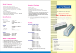
1
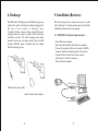
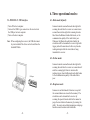
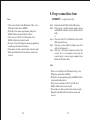
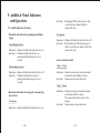
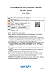
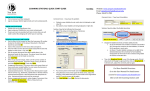
User's Manual
Bluetooth Scanners
BT Series
IM-MANU-BT-EM
Contents
1. Introduction........................................................
2
2. Available models................................................
2
3. Standard package...............................................
3
4. Recharge............................................................
4
5. Installation (Receiver) ......................................
5
6. Three operational modes...................................
9
7. Scanner programming.......................................
11
8. Purge scanned data from scanner...................... 13
(recapture mode only)
9. Audible & Visual Indicators and Operation...... 14
-1-
1. Introduction:
3. Standard package:
The BT series incorporate Bluetooth wireless technology
which offers customers a freedom of mobility with up to 50
meters working range from receiver. The scanner is
configured to work as master mode, when it at Bluetooth
radio link on state, which makes attempts to connect with
receiver whenever the radio link breaks. With exceptional
power saving design, the scanner operates much longer than
your expectation on a full battery recharge circle.
Furthermore, user friendly operation and large memory
capacity characteristics give BT series a jump on its clone.
BT-XXXX-X series
2. Available models:
·
·
·
·
·
·
·
Scanner
Receiver
USB retrieving power cable
Utility CD disk
User's manual
Reader's external power adapter (option)
RS-232 interface receiver comes with PS/2 retrieving
power cable (default)
· RS-232 interface receiver external power adapter
(option)
2.1. Extra Long Range CCD Scanner
·
·
·
·
BT-4505-K (Keyboard Wedge)
BT-4505-R (RS-232)
BT-4505-U (USB RS-232)
BT-4505-UK (USB Keyboard Wedge)
2.2. Laser Scanner
· BT-3805-K (Keyboard Wedge)
· BT-3805-R (RS-232)
· BT-3805-U (USB RS-232)
· BT-3805-UK (USB Keyboard Wedge)
-2-
-3-
4. Recharge:
5. Installation (Receiver):
The LED turns to FLASH green as the USB retrieving power
cable or the reader's external power adapter is plugged in to
DC jack of the scanner, as drawings show.
It indicates that the scanner is being charged. During the
charging mode, the scanner is neither read a barcode nor
send data to receiver. The whole charging process takes
around 4 hours since the charge started, when the LED
becomes STEADY green, it indicates that the scanner
finishes the charge process.
BT series' paring between scanner and receiver is made
before shipment. So, normal operation can be started after
installation of the receiver to host computer.
5.1. BT-XXXX-K: Keyboard wedge interface
· Turn off the host computer.
· Disconnect the keyboard cable from host computer.
· Connect the keyboard cable into the female 6-Pin DIN
connector which located at long cable of the receiver.
· Connect the short cable of the receiver into the
keyboard port on the host computer.
· Turn on the host computer.
To PC keyboard port
USB retrieving power cable
reader's external power adapter
To keyboard cable
-4-
-5-
5.2. BT-XXXX-R: RS-232 interface
5.2.1. Using PS/2 retrieving power cable (default)
5.2.2. Using external power adapter (option)
· Turn off the host computer.
· Connect the D-type 9-pin cable connector of the
receiver to the proper COM port on host computer.
· Disconnect keyboard cable from keyboard port.
· Connect the PS/2 retrieving power cable to the
keyboard port on the host computer.
· Connect the keyboard cable into the female 6-Pin DIN
connector of the PS/2 retrieving power cable.
· Connect the DC plug from the branched cable of PS/2
retrieving power cable into the D-type 9-Pin
connector's DC jack.
· Turn on the host computer.
· Turn off the host computer.
· Connect the D-type 9-pin cable connector of the
receiver to the proper COM port on the host computer.
· Connect the DC plug of the external power adapter to
the D-type 9-pin connector's DC jack of the receiver.
· Connect the external power adapter into an AC outlet.
· Turn on the host computer.
Note: Application software must include RS-232 utility to
obtain the data from COM port which connects the
receiver.
Note: Application software must include RS-232 utility
to obtain the data from COM port which connects
the receiver.
To RS-232 port
To PC RS-232 port
To DC jack
To PC keyboard port
AC power Source
PS/2 retrieving power cable
To keyboard cable
-6-
-7-
6. Three operational modes:
5.3. BT-XXXX-U: USB interface
6.1. Batch mode (default):
· Turn off the host computer.
· Connect the USB A type connector on the receiver into
the USB port on host computer.
· Turn on the host computer.
Note: When configuring the receiver, the USB driver must
be prior installed. The driver can be found from the
bundled CD disk.
Scanner transmits scanned barcode data right after
scanning barcode label to receiver or scanner stores
scanned barcode data right after scanning barcode
label when the Bluetooth radio link breaks, or the
communication quality of the radio link is poor.
Whenever the Bluetooth radio link rebuilds, the
stored data will be transmitted to receiver right after
trigger pushed. Scanner doesn't allow any barcode
reading attempts while the stored data is being
transmitted to receiver.
6.2. On-line mode:
USB port
Scanner transmits scanned barcode data right after
scanning barcode label to receiver or scanner doesn't
emit the scanning light from its window after
pushing trigger when the Bluetooth radio link breaks
or the communication quality of the radio link is
poor.
6.3. Recapture mode:
Scanner acts as Batch mode's behaviors except all
the scanned dataum are stored in the memory. The
stored data can be transmitted to receiver by
scanning the special barcode label at the manual or
purge the stored data in the memory by running the
utility. To execute stored data transmission and purge
functions must be under radio link builds.
-8-
-9-
7. Scanner programming:
Note: There is no feedback protocol between host computer
and receiver no matter what which interface
equipped. The radio link between the scanner and the
receiver can work well as long as stable power
continuously supply for both of them. Most
computers provide +5V DC power from keyboard
port or USB port even they are at power off state. So
it might be a risk to loss the scanned data when
operator works in the field while host computer acts
abnormally such as hang-up, power off, etc. This
mode provides the last chance to trace back the data.
Barcode attachment: To read the barcode to transmit data
in the scanner's memory to PC.
-10-
The BT series can be configured via the Windows base
programming utility to meet special application needs such
as decoding options, code ID settings, etc.
Step 1. Run the bundled CD disk :\utilities\BTScanner.
Step 2. If the receiver is keyboard wedge interface, please
install KBIDrv (interface driver) and follow by BT
utility.
or
Step 2. If receiver is RS-232 or USB interface, then, install
BTScanner utility only.
Step 3. After step 2, please follow the dialog boxes of the
utility to do the necessary parameters programming
to meet your application needs and transmits it.
Step 4. After step 3, the programmed values are stored at
the receiver. So, it is a compulsory step to push the
scanner trigger to transmit the programmed values
from receiver to scanner to complete the scanner
programming procedure under Bluetooth radio link
is built.
-11-
8. Purge scanned data from
scanner: (recapture mode only)
Note:
· There are two folders in the BTScanner Utility, one is
BTScanner and another is KBIDrv.
· BT folder is the scanner programming utility and
KBIDrv folder is keyboard interface driver.
· If the receiver is RS-232 or USB interface, then,
KBIDrv folder doesn't need to install.
· Be aware of that performing the scanner programming
would purge the data in the memory.
· Please make sure that to perform Step 4 must be under
Bluetooth radio link built state between scanner and
receiver.
Step 1. Run the attached CD disk:\utilities\BTScanner.
Step 2. If the receiver is keyboard wedge interface, please
install KBIDrv (interface driver) and follow by BT
utility.
or
Step 2. If receiver is RS-232 or USB interface, then, install
BTScanner utility only.
Step 3. After step 2, please follow the dialog boxes of the
utility to do the purge job.
Step 4. After step 3, the purge command is stored at the
receiver. So, it is a compulsory step to push the
scanner trigger to execute purge command when
Bluetooth radio link is built.
Note:
· There are two folders in the BTScanner Utility, one is
BTScanner and another is KBIDrv.
· BT folder is the programming utility and KBIDrv folder
is keyboard interface driver.
· If the receiver's interface is RS-232 or USB, then,
KBIDrv folder doesn't need to install.
· Please make sure that to perform Step 4 must be under
Bluetooth radio link built state between scanner and
receiver.
-12-
-13-
9. Audible & Visual Indicators
and Operation:
Operation:
9.1. Audible indicators (Scanner)
· Bluetooth radio link status by pushing and holding
trigger
5-ascending tone beep
Indications: Indicates the Bluetooth radio link set to on.
Operation: At Bluetooth radio link off state, by
pushing and holding trigger for over 5
seconds.
By plugging USB retrieving power cable
or external power adapter cable into
scanner's DC jack.
No response
Indications: Indicates the Bluetooth radio link set to off.
Operation: By disconnecting USB retrieving power
cable or external power adapter cable from
scanner's DC jack.
· Good read and transmits
5-descending tone beep
1 beep + 1 beep
Indications: Indicates the Bluetooth radio link set to off.
Operation: At Bluetooth radio link on state, by
pushing and holding trigger for over 5
seconds.
Indications: Indicates barcode good read and transmit
scanned data successfully to receiver.
Operation: Operate scanner to read a barcode.
1 beep + 3 beep
· Bluetooth radio link status by plug in / disconnecting
power device
No response
Indications: Indicates barcode good read but transmit
scanned data failed to receiver.
The scanned data will be stored in the
memory.
Operation: Operate scanner to read a barcode.
Indications: Indicates the Bluetooth radio link set to on.
-14-
-15-
· Low power status
2 beeps before scanner emits the red light
Indications: Indicates the scanner is at low power state.
Operation: Operate scanner to read a barcode.
Note: It is approximately 250 scans to the scanner shut
itself down since the low power status starts
warning.
Note:
· Whenever the free memory available less than to 4
KB, the memory full status starts warning.
· BT series offer 192KB memory for keeping data.
It is roughly stored EAN 13 barcode up to 15,000
scans.
· Programming to be done successfully
10 tone beeps
· Memory full status
1 beep + 1 beep + 2 beeps
Indications: Indicates barcode good read and transmit
scanned data successfully to receiver, the
scanned data will be stored in the memory
and notices the memory is at near full state.
(Recapture mode)
Operation: Operate scanner to read a barcode.
1 beep + 3 beeps + 2 beeps
Indications: Indicates barcode good read but transmit
scanned data failed to receiver, the
scanned data will be stored in the memory
and notices the memory is at near full state
(Recapture mode, or possibly Batch mode)
Operation: Operate scanner to read a barcode.
-16-
Indications: Indicates scanner has programmed
successfully.
Operation: Refer to user's manual part 7.
Scanner Programming.
· Purge scanned data from scanner
6 tone beeps
Indications: Indicates scanner's memory has been
purged successfully.
Operation: Refer to user's manual part 8.
Purge scanner data from scanner.
-17-
9.2. Visual indicators
· Bluetooth radio link status (scanner)
·Bluetooth radio link status (receiver)
Red LED off
Red LED flash
Indications: Indicates the scanner is at Bluetooth radio
link off state.
Operation: To enable Bluetooth radio link on state,
by pushing and holding the trigger over 5
seconds.
Indications: Indicates Bluetooth radio link with scanner
break (it's possibly caused by poor
communication quality or radio link is set
to off state.)
Operation: To enable Bluetooth radio link on state, by
pushing and holding the trigger over 5
seconds or shorten the distance between
scanner and receiver or adjust the direction
of the scanner.
Red LED flash
Indications: Indicates the scanner is at Bluetooth radio
link on state and the scanner makes
attempts to connect with receiver.
Operation: To wait few seconds or shorten the
distance between scanner and receiver or
adjust the direction of scanner which help
scanner attempts to connect with receiver.
Red LED on
Red LED on
Indications: Indicates Bluetooth radio link with scanner
set to on.
Operation: To disable the radio link on state by
pushing and holding the trigger over 5
seconds.
Indications: Indicates the scanner is at Bluetooth on
state and the radio link between the
scanner and the receiver is built.
Operation: To disable the radio link on state by
pushing and holding the trigger over 5
seconds.
-18-
-19-
· Programming to be done successfully (scanner)
Green LED on then Red LED on
Indications: Indicates programming to be done
successfully.
Operation: Refer to user's manual part 7.
Scanner programming.
· Purge scanned data from scanner (scanner)
Green LED on then Red LED on
Indications: Indicates scanner purge scanned data
successfully.
Operation: Refer to user's manual part 8.
Purge scanned data from scanner.
Green LED On
Indications: Indicates the scanner (battery) is at full
charged state.
Operation: It takes about 4 hours to complete the
charging process.
· Scanning barcode label (scanner):
Green LED on then off
Indications: Indicates the scanner performs a good
barcode read.
Operation: Operate scanner to read a barcode.
·Memory full status (scanner):
Green LED flash after trigger push and no scanning
light emit from scanner window
· Recharge (scanner)
Green LED Flash
Indications: Indicates the scanner is at charging state.
Operation: When DC plug either from external power
adapter or USB retrieving power cable
plug in to DC jack on the scanner.
-20-
Indications: Indicates scanner is at memory full state.
Operation: To transmit the storage data to host or
purge the data.
-21-