1
Angenent
Lab
–
MCU
Potentiostat
–
User
Manual
Elliot
Friedman
&
Alex
Lee
1. Overview
This
user
manual
will
provide
the
user
with
an
overview
of
the
microcontroller
(MCU)
based
potentiostat
developed
in
the
Angenent
Lab,
and
instructions
for
its
use.
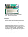
1.1. Parts
Upon
opening
the
black
box,
you
will
find
six
(6)
different
boards,
arranged
as
shown
below:
The
function
of
each
board
is:
Main
Board
–
Contains
the
power
for
the
device
and
houses
the
microcontroller.
Connects
to
and
controls
all
other
boards.
The
liquid
crystal
display
(LCD)
connects
to
this
board.
SD
Board
–
Contains
the
secure
digital
(SD)
card
for
data
storage.
Contains
the
switch
to
turn
the
LCD
screen
on/off.
E1,
E2,
E3
–
Contains
circuitry
for
electrodes
1,
2,
and
3,
respectively.
Auxiliary
Board
–
Contains
circuitry
to
process
signals
between
E1,
E2,
&
E3
and
the
main
board.
1.2. Additional
Components
In
addition
to
the
black
box,
there
is
a
liquid
crystal
display
(LCD)
screen
that
plugs
into
the
main
board
for
real‐time
feedback
and
adjustments.
Finally,
you
will
need
a
small
flathead
screwdriver
to
adjust
applied
potentials.
2. Functions
2.1. LCD
Operation
Plug
the
LCD
wire
into
the
main
board.
The
LCD
should
turn
on,
but
not
display
anything
cohesive.
To
activate
the
LCD,
flip
the
switch
on
the
SD
card
board.
This
will
reinitialize
the
LCD
in
its
default
state.
In
the
default
state,
you
can
see
the
date
and
time
settings
of
the
CPU
and
an
operating
parameter
call
shift.
Angenent
Lab
–
MCU
Potentiostat
–
User
Manual
Elliot
Friedman
&
Alex
Lee
There
are
four
buttons
on
the
board.
In
order
from
left
to
right,
these
buttons
are:
SET
button
Goes
into
set
mode
so
user
can
change
data
INC
button
Increments
value
STAT
button
Rotates
between
the
clock
screen
and
the
electrode
data
UPDT
button
Quickly
updates
electrode
data
2.2. Adjusting
the
clock
To
adjust
the
clock,
hold
the
SET
button
down
while
on
the
clock
screen.
This
button
will
scroll
through
the
date
and
then
the
time
to
make
changes.
To
increment
the
value
that
the
cursor
is
currently
at,
press
and
hold
the
INC
button.
Holding
it
down
will
allow
the
value
to
continue
to
increment.
After
the
correct
time
is
set,
continue
to
hold
down
the
SET
button
until
the
cursor
disappears.
This
will
return
the
potentiostat
to
its
normal
operating
mode
and
print
a
message
on
the
SD
card
noting
that
the
time
was
changed.
2.3. Checking
the
readings
You
can
check
the
current
status
of
each
channel.
To
scroll
between
the
time
indicator
and
the
electrode
statuses,
press
the
STAT
button.
This
will
scroll
through
each
electrode
channel
before
returning
to
the
date
channel.
Each
status
channel
will
display
the
last
taken
measurement
of
the
voltage
being
applied
across
the
electrode
and
the
current
being
read
in.
Pressing
the
UPDT
button
will
cause
the
CPU
to
take
a
new
measurement
at
that
electrode
and
display
the
results
on
the
LCD
screen.
No
data
will
be
written
to
the
SD
card.
The
default
setting
is
to
apply
a
negative
voltage
across
the
electrode.
If
the
user
desires
to
apply
a
positive
potential,
press
the
SET
key.
A
zero
represents
a
negative
potential
while
a
one
represents
a
positive
potential.
The
next
number
is
the
resistance
applied
to
multiply
the
current.
Change
the
value
to
the
correct
resistance.
Holding
down
the
SET
key
will
return
the
screen
to
displaying
the
current.
2.4. Removing
the
LCD
screen
To
remove
the
LCD
screen,
flip
the
switch
on
the
SD
card
board
down
and
pull
the
LCD
screen
and
cable
out
of
the
main
board.
The
switch
will
stop
data
from
being
sent
to
the
LCD.
Angenent
Lab
–
MCU
Potentiostat
–
User
Manual
Elliot
Friedman
&
Alex
Lee
2.5. Resetting
the
SD
Card
Anytime
after
the
SD
card
is
removed,
it
will
need
to
be
reset.
To
do
this,
pull
the
SD
card
board
out
and
push
the
black
button
on
it.
If
the
LCD
screen
is
plugged
in
and
on,
and
the
screen
is
currently
in
the
clock
view,
the
second
line
of
the
LCD
screen
will
read
“SD
card
reset.”
2.6. Adjusting
the
applied
potential
2.6.1.
Polarity
and
current
range
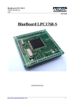
The
electrode
board
is
showed
above
with
the
applicable
connections
and
jumpers.
J1
should
always
be
connected
to
from
the
center
pin
to
the
right
pin.
J2
and
J3
control
the
current
range,
and
can
be
adjusted
as
described
in
the
table
below.
The
default
setting
should
be
for
a
1mA
range.
Current
Range
Jumper
Setting
200
µA
J2,
Center‐Left
pins
connected
400
µA
J2,
Center‐Right
pins
connected
1
mA
J3,
Center‐Left
pins
connected
2
mA
J4,
Center‐Right
pins
connected
Note:
Changes
in
current
range
should
be
noted
by
the
user
and
changed
via
the
LCD
screen
(see
section
2.3).
Jumpers
4,
5,
&
6
control
the
polarity
of
the
applied
voltage
to
the
working
electrode.
To
apply
a
positive
voltage,
connect
the
center
pin
to
the
right
pin
of
J4,
J5,
and
J6.
To
apply
a
negative
voltage,
connect
the
center
pin
to
the
left
pin
of
J4,
J5,
&
J6.
Note:
Changes
in
polarity
should
be
noted
by
the
user
and
changed
via
the
LCD
screen
(see
section
2.3).
Angenent
Lab
–
MCU
Potentiostat
–
User
Manual
Elliot
Friedman
&
Alex
Lee
Note:
The
SD
card
and
LCD
screen
display
will
always
show
a
1
kΩ
resistance
calculation.
If
the
resistance
is
not
at
1
kΩ,
the
LCD
screen
data
and
the
SD
card
data
will
be
off
by
the
ratio
{set
resistance/1
kΩ}.
The
resistance
value
is
stored
to
the
SD
card
so
that
the
correct
readjustments
can
be
made
by
the
user
when
analyzing
data.
2.6.2.
Magnitude
To
adjust
the
magnitude
of
the
applied
potential,
use
the
screwdriver
to
turn
the
potentiometer
(labeled
P
in
diagram).
To
decrease
the
magnitude,
turn
the
dial
clockwise.
To
increase,
turn
the
dial
counter‐clockwise.
Use
the
LCD
screen
(section
2.3)
to
assist
in
setting
the
correct
potential.
2.7. Adjusting
the
shift
The
shift
is
an
operating
parameter
that
may
need
to
be
adjusted
by
the
user.
For
normal
operation
under
a
1
mA
current
range,
the
shift
should
be
set
to
550
mV,
making
the
range
of
readable
currents
‐550
µA
to
550
µA.
To
adjust
the
shift
to
the
correct
value,
use
the
potentiometer
located
on
the
auxiliary
board.
To
decrease
the
magnitude,
turn
the
dial
clockwise.
To
increase,
turn
the
dial
counter‐clockwise.
Confirm
the
correct
value
using
the
LCD
screen
(section
2.1).
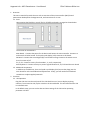
2.8. Programming
the
Microcontroller
If
the
need
to
program
the
chip
arises,
attach
the
programming
device
to
your
PC
(via
USB)
and
connect
the
other
end
to
the
6
pins
found
near
the
bottom
of
the
main
board.
The
red
wireshould
connect
to
the
left
side
of
the
board.
Make
sure
that
the
jumper
connector
below
the
6
pins
is
inserted,
otherwise
the
chip
will
not
program.
Open
up
AVRstudio.
Go
to
the
project
folder
and
open
up
potentiostat.aps.
The
project
should
open
up.
Follow
the
instructions
found
on
this
website
to
make
sure
that
the
data
is
stored
correctly.
http://winavr.scienceprog.com/avr‐gcc‐tutorial/using‐sprintf‐‐function‐for‐float‐
numbers‐in‐avr‐gcc.html
(instructions
begin
near
the
bottom,
starting
with
“You
may
ask
what
to
do
with
AVRStudio
settings,
where
makefile
is
generated
automatically.
Well
things
are
simple
too
in
this
situation.”
Then
go
to
Project>>Configuration
Options
and
make
sure
that
the
device
is
“Atmega644”
and
the
frequency
is
set
to
“16000000”
Hz.
The
potentiostat
is
currently
set
to
record
data
every
hour.
To
change
this
setting,
go
to
source
files
on
the
left
bar.
And
open
main.c.
Right
at
the
top
there
is
a
macro
called
record_trigger().
This
tells
the
device
when
to
record
data.
To
set
which
hours
you
want
the
potentiostat
to
record,
change
the
(hour==xx)
to
be
whatever
hours
you
want.
If
you
want
it
to
record
every
single
hour,
remove
all
the
hour
lines.
Keep
the
msec,
sec,
and
min,
instructions,
as
ensures
that
it
records
only
once
in
that
time
and
not
constantly.
Hit
F7
to
program
the
device.
If
there
are
errors
make
sure
you
go
and
fix
them.
Go
to
Tools>>Program
AVR>>Connect.
Select
the
platform
“AVRISP
mkII”
and
Port
“USB.”
Hit
connect.
A
new
window
should
appear.
Go
to
the
Program
tab
and
in
the
Flash
menu,
hit
the
…
to
browse
the
file
location.
Go
into
the
project
folder
“/default/potentiostat.hex”.
Then
hit
the
program
button.
This
should
program
the
device.
3. Connections
Angenent
Lab
–
MCU
Potentiostat
–
User
Manual
Elliot
Friedman
&
Alex
Lee
3.1. Connections
between
boards
The
unit
should
have
all
connections
in
the
correct
position
at
the
beginning
of
use,
but
if
the
need
arises
to
unplug
or
re‐connect
the
boards,
the
correct
configuration
is
outlined
below:
Auxiliary
Board
Connections:
A1
–
Connects
to
main
board
via
3‐prong
connector
A2
–
Connects
to
E1
board
via
4‐prong
connector
A3
–
Connects
to
main
board
port
labeled
‘E1’
A4
–
Connects
to
E2
board
via
4‐prong
connector
A5
–
Connects
to
main
board
port
labeled
‘E2’
A6
–
Connects
to
E3
board
via
4‐prong
connector
A7
–
Connects
to
main
board
port
labeled
‘E3’
The
SD
board
connects
to
the
main
board
via
the
10‐prong
connectors
on
either
board.
3.2. External
connectors
There
are
three
external
connectors:
a
6‐pin
connector,
a
3‐pin
connector,
and
(depending
on
the
unit)
either
a
2‐pin
or
another
3‐pin
connector
labeled
with
blue
tape.
The
six
pin
connector
connects
to
the
working
and
counter
electrodes.
The
unlabeled
3‐pin
connector
connects
to
the
reference
electrodes.
The
labeled
2‐
or
3‐pin
connector
connects
to
the
power
source.