1
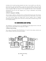
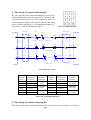
WS420 WJ Emergency Device for Evolution Elevator USER MANUAL Shanghai Wenshnag Innovative Technology Co., Ltd. Content 1. Summarization . . . . . . . . . . . . . . . . . . . . . .1 2. Operation principle . . . . . . . . . . . . . . . . . . . .2 3. Installation and wiring . . . . . . . . . . . . . . . . . . .4 4. Commissioning procedure . . . . . . . . . . . . . . . . .8 5. Maintenance notice . . . . . . . . . . . . . . . . . . . .10 ! ☆ CAUTION Thank you for using our product. For the sake of your normal use and ensure the safety of elevator and this product, please read the user manual completely before attempting to install. ☆ please carefully check the model and parameters on the nameplate of this product with relevant parts of elevator. If there is any nonidentical please contact with engineering dept of our company immediately to consult the solution instead of installation and adjustment. ☆ Don’t touch the high voltage part in the product during adjusting. ☆ If this product hasn’tput in use over six months from the date of exWorks (for example, when it has not been unpacked or the elevator hasn’t put in use though this product has been installed), Please charge the batteries according to below method. Connecting B3-7 and B3-8 with L、N (power 220V), shorting B3-9 and B3-10, power ON the switch on the front panel of the device, and charge it for 24 hrs. ☆ This manual is subject to change without notice. 1. Summarization WS420WJ emergency device is an elevator safety device for emergency rescue when a power failure occurs. In case of sudden power-failure, this device will automatically put into use and supply electric energy required by the elevator, and drive elevator running to the nearby leveling position, then open the car door and hall door to let passengers out of elevator safety. 1) Product model WS420 WJ □□ Motor current Evolution elevator Code of emergency device 2) Technical parameters Input voltage: AC380V Batteries: 12V/ 17 AH ×4 Driving Power: ≤30 KW 3) Working environment Temperature: -10 to 60℃ Relative humidity: < 95%, no condense There shouldn’t be excessive erosive gases or dust 4) Profile structure Fig.1 Profile structure - 1 - 2. Operation principle Operating principle of WS420WJ emergency device for evolution refer to fig.2. 1) Power detect When external power is supplied normally, the powers detect circuit in the emergency device will give signal that showing the external power is OK. Batteries of the device are automatically charged by charging circuit to keep in level of rated voltage. The circuit has the over-charging, short-circuit and over-current protections. Input power Detect Interface with the electric system of the elevator Charging Circuit PLC Control system Batteries Current sensor Door motor Controller DC converter Three – phase Inverter Door motor Breaker Traction machine Fig.2 Operating principle diagram 2) Emergency operation When elevator suddenly encounters power break down and stops, PLC control system of the emergency device will instantly detect state of the elevator and automatically be put into emergency rescue. At first, it disconnects with the external power, then inspects whether the batteries are normal or not, if they are, the device will start DC converter to supply DC power source to leveling detection circuit and motor controller. When signal of floor leveling is caught, the door-motor will get voltage to open car door and hall door. If the car is not at the floor-leveling position, DC converter will provide electric power to breaking circuit and loose the break, and three-phase inverter will supply power to traction machine let it runs forward definite direction. After the car landing at the position of floor leveling, the three-phase inverter will be stopped and breaker will be closed too. And then both the car door and hall door will be opened. Later the device will restore the control system of the elevator to the state before emergency rescue and automatically turn off the power of emergency device. 3) Security interlock If it is judged that the elevator running is stopped due to the breakdown of safety circuit or door locking circuit, in accordance with the elevator “safety standard” condition, the emergency device will not put into rescue running. Even during rescue running, the signals of safety circuit and door - 2 – Contrl Power R1 S1 T1 3 L(B3-7) N(B3-8) R(B3-1) S(B3-2) T(B3-3) 1 3 B3-4 B3-5 B3-6 Car Fig.3 General wiring drawing of the emergency device - 3 - checking circuit is under inspecting constantly. Once there is some trouble in any of the above loops, this device will stop immediately to ensure the safe and reliability of the persons and the elevator. Similarly, the device is monitoring the inspecting loop of the elevator control system constantly. When the elevator is to be inspected the device will be interlocked automatically and won’t put into emergency run so long as maintenance men pressing inspecting switch. 4) End of emergency running After emergency running is ended the device is disconnected from the parts of the elevator control system and kept in the isolation but awaiting-orders state without affect on the normal run of the elevator. When the external power recovers, batteries will be recharged automatically by the charging circuit of the device and keep them in sufficient energy for the next emergency running. 3. Installation and wiring The installation of emergency device is easy and handy, just only hang the device on the wall near the elevator control cabinet. The wiring refers to figure 3. 1) Main circuit wiring Next, connect TD terminal’ s TD-U,TD-V,TD-W to U, V, and W of the cabinet, which is the power terminal, connected to the traction machine. L1 T1 L2 T2 L3 T3 201:1 U S V T W B3 N R 1 1 9 4 R0 S 2 2 10 5 S0 7 K12 B3 V R2 204 1 2 3 4 5 6 R4 B3 11 R3 12 Fig. 4 Main circuit wiring - 4 - K12 R1 U1 11 3 V1 12 4 M W 6 T0 8 U K10 control power L T 3 201:2 R TD-U TD-V TD-W 2) The wiring of control cable plug B1 B1 is the special control cable connecting the security, door Lock and inspecting loops in the hoist way. The plug of B1 is inserted into the socket B1 of the emergency device, another connected to the elevator control cabinet. The wiring refers to table2 and figure 6. The arrangement sequence of B1 (as well as B2, B3) is showed as table 1. WS420-B1 K1 B1-3 STOP WS420-B1 STOP SSG B1-1 1 Tab.1 Arrangement of B1 B1-2 9 10 (IN CAR) (ON CAR) B1-7 SMH1 K1 2 SAFE LOOP SMHN SMCo B1-5 B1-6 B1-8 K1 12 11 3 B1-4 K1 4 DOOR LOCK LOOP SAP K2 B1-11 1 SAT SAL K2 B1-10 B1-9 10 9 B1-12 2 (CAR TOP) (IN CAR) INS LOOP Fig. 6 Hoist way circuit Terminal name B1-1 The contact has been linked in the device K1-9 B1-2 K1-10 B1-3 K1-1 B1-4 K1-2 B1-5 K1-11 B1-6 K1-12 The circuit should be connected Safety loop Input Safety loop Output Door lock loop input Terminal Name B1-7 The contact has been linked in The device K1-3 B1-8 K1-4 B1-9 K2-9 B1-10 K2-10 B1-11 K2-1 B1-12 K2-2 The circuit should be connected Door lock loop output Inspecting loop input Inspecting loop output Tab.2 The wiring illustration of B1 3) The wiring of control cable plug B2 B2 is the special control cable connected the door zone sensor and door motor etc. the plug - 5 - B2 should be plug into socket B2, another terminal connected to the elevator control cabinet. The wiring of B2 connected to evolution controller factory as table 3 and fig 7. B2-1 The contact has been linked in the device K3-7 The circuit or part should be connected 24V B2-7 The contact has been linked in The device K5-8 The circuit or part should be connected K14-8 B2-2 K3-8 0V B2-8 K5-4 K14-7 B2-3 K2-11 door zone input B2-9 K5-5 K14-10 B2-4 K2-3 door zone output B2-10 K5-6 K14-9 B2-5 K3-5 K3-5 B2-11 K7-no Breaker + B2-6 K5-12 com B2-12 K8-no Breaker - Terminal Name Terminal Name Tab.3 The wiring illustration of B2 To VVVF door motor, the 5 wires in traveling cable should be used to connect the B2 socked in evolution controller with door motor. The relays K14 is in wire connect with door motor controller on the top of the car. Refer to fig 8. The B2-11 and B2-12 of B2 has already been in controller and connected to the positive and negative terminals of breaker circuit as fig. 9. DOOR ZONE +24/48V B2-1 B2-2 0V PAD K3 +24/48V 7 11 K3 8 DZU B2-3 Fig. 7 12 B2-4 K2 11 -0V 3 Door zone sensor wiring oor motor control Fig. 8 Door motor wiring 4) The wiring of control cable plug B3 B3 is the special cable connecting the power supply to the control parts of elevator and AC power supply to emergency device. The wiring is showed as fig.3、fig.4 and tab. 6. First, - 6 – DZ WS420-B2 K7 +110V 30 B+ YBK WS420-B2 B抱闸回路 B2-11 K8 B2-12 87 87 0V 30 Fig. 9 breaking circuit wiring R, S, T of the control power should be disconnect from terminals R, S, T of the elevator control cabinet, and the B3-1,B3-2,B3-3 of the B3 cable connected to R,S,T (refer to fig3, fig.4). And then connect control power to the B3-4, B3-5, B3-6, (R0, S0, and T0). I.e. the device is connected in serial between the main power and control power. B3-9 and B3-10 connect to a power switch. If no switch you should shout connect B3-9 and B3-10. The B3-11 and B3-12 must connected to U1 and V1 just only when short current relay for U,V,W of motor has been used. The contact has been linked in the device K12-1 K12-2 Terminal Name B3-1 B3-2 B3-3 B3-4 B3-5 B3-6 The circuit should be connected R S T R0 S0 T0 K12-9 K12-10 Terminal Name B3-7 B3-8 B3-9 B3-10 B3-11 B3-12 The contact has been linked in The device L N 24VI 24VO K12-3 K12-4 The circuit should be connected L N 24VI 24VO U1 V1 The code and name of main parts in the emergency device are showed as table 4. Num. Code Name Num. Code 1 F1 63A Circuit breaker 10 K8 Breaker relay 2 F2 4A Fuse 11 K9 Discharge relay 3 K1 Safety relay 12 K10 380V power relay 4 K2 Inspect relay 13 K11 Power detector 5 K3 24V power relay 14 M1 Charger model 6 K4 Run relay 15 M2 DC Charge model 7 K5 Door relay 16 M3 Drive model 8 K6 48V Power relay 17 M4 PLC 9 K7 Breaker relay 18 M5 Inverter Tab.4 The code and name of main part - 7 - Name 4. Commissioning procedure 1) Parts check Check carefully whether the parts such as connectors, relays and terminals and so on in the device are loose or fall off due to shipment, tighten them if any. 2) Wiring check Please check the wiring that has been connected in according to the drawings of the elevator control system and the ones provided by this user manual. Especially have to be attention: Power wires should not be connected on the I/O signal terminals of the emergency device. B1, B2, B3 plugs should not be inserted to wrong place with each other. Otherwise, it maybe damage the device and the elevator, or hinder regular to you. There is no any problem affirmed through the above checks then the following can be conducted. 3) State adjustment of safe, door lock and inspecting loops Taking off B1 plug in the device and measure the safety loop between B1-1, B1-2 of cable B1 with the Ω rang on multi-meter. It should be “short ”state when all switch elements in the loop are normal. The measurements of the door lock loop between B1-5, B1-6 and the inspecting loop between B1-9, B1-10 is as the same as the safety loop. Both should be “short ”state too. After the measurements finished B1 plug have to be put into socket B1. 4) Check the input to emergency device signals from elevator Putting the power switch of the device OFF, the elevator should run normally. If it does not so, check whether the wiring between the safety, door and inspecting loop are correct or not. 5) Check emergency device power If the elevator can run normally, stop it at the floor-leveling position. And then turn off the three-phase power and 63A circuit breaker in the emergency device, then the emergency device switch and B3 power switch are put at the “on”position and the three-phase power is applied to it again, check if the power is correct. When it is correct the red indicator LED on the emergency device front panel will light, and after ten second’ s delay, the Y0 indictor of PLC in the device will light. Only at this time, conduct the next step adjustment. 6) Check the logic action at the floor-leveling position First turn off the three-phase power. If the car door and hall door are closed, the input signal LED X2 (security loop), X3 (door lock loop) and X4 (inspecting loop) on PLC in the emergency device will all light. The transform command output Y2, the detect command output Y3 and the opening door command output Y5 of PLC will light too. Supposing the floor-leveling sensor is effective on low level (such as magnetic switch), the input of PLC X5 (door zone) should light. On the contrary, If the door zone sensor is effective on high level (e.g. photoelectric switch), the sensor outputs 24V and X5 will not light (the terminal is cut down). The green LED on the emergency device panel should light at such both situations. - 8 - Note: The elevator shouldn’t be in Maintenance, or it won’t respond. 7) Check the logic action at the non-floor-leveling position First turn on the three-phase power, move the elevator down until about 50cm away from the door zone by inching and restore the inspecting switch at the normal position. Then turn off the three-phase power, PLC of the device acts according to the following sequence: as for the input of PLC, only X2, X3, X4 are light showing the safety loop, door lock and inspecting loops are normal;Y2 (light) outputs transform command → Y3 (light) outputs detect command → Y4 (light) outputs emergency run command at this time. Moreover, the green LED on the device panel should light while the device is acting. 8) Adjust the emergency running Put the emergency device power switch “OFF”, turn on 63A circuit breaker, disconnect the wire from Y1 of PLC and turn on the three-phase power. Then turn the emergency device power switch “ON”, when Y0 is light, turn off the three-phase power again. At this time the elevator is in the emergency state and moves up at a low speed (If it down or doesn’t move, interchange the power phase-sequence from the emergency device to the traction machine). The car door and hall door should be opened when the elevator arrival the floor leveling. 9) Adjust the orientation Repeat step 8. When the elevator moves up as a emergency response, turn slowly the potentiometer W1 clockwise, witch at the right bottom corner of the three-phase inverse conversion PCB. Until the red indicator L6 by the side of W1 is light, and then turn it back (counter clockwise) until L6 is extinguish, the turning back is a little more after L6 is just extinguish. When the step over, resume the wiring of Y1. Note: Moving down is the least disadvantageous condition when elevator is no-load, so don’t repeat using this function many time within short time, please. The code and meaning of I / O terminal of PLC in the device are showed as table 5. Input terminal X0 X1 X2 X3 X4 X5 Meaning Current Power failure Safety Door-lock Inspection Door zone Input terminal X6 X7 Traction Fault Y0 Y1 Y2 Y3 Y4 Y5 Power Direction Transform Check Run Open door Meaning output terminal Meaning Tab.5 The code and meaning of I / O terminal of PLC - 9 – 5. Maintenance notice WS420WJ emergency device for elevator is exempt from Maintenance product. But as safety rescue equipment, we suggest that inspection of following items should be conducted to the device too, while you are examining elevator regularly to ensure the device is in good condition. 1) Batteries voltage measuring Measure the output of the batteries once monthly to see whether they are in the rated voltage status. When examining, put the power switch of the device “OFF”. Measure the output E1, E2 of the battery box with DC voltage rang of multi-meter (refer to figure 10). They should be ≥24V and yet the difference of each other can’t be >1V. If the above requirements don’t be conformed, you should consider displacing the batteries whose working life are generally 2~3 years. After finishing measurement, restored the power switch of the device at “ON ”. 2) Check charger Check the charger in the emergency device once per six months. When the device is power “ON ”and the three-phase power is normally supplied, measure the outputs E1, E2 of the batteries. The both E1, E2 should be ≥25.5V (or should be > 24V at least ) and yet the difference of each other can’t be > 1V too. The charger is good if the mentioned requirements are satisfied. 3) Simulating emergency run The emergency device should has simulating emergency running once at the intervals of six months, which is proceeded at the supply of normal three-phase power. First moves the elevator down about 50cm away from the door zone by inching and restore the inspecting switch at the normal position. Then turn off the three-phase power and the green LED on the front panel of device will light at this moment. The elevator run up to the door zone and then door will be opened automatically. Await the green LED is go out i.e. simulating emergency run is ended, turn on the three-phase power again. The red LED on the front panel of device will light which shows the device is in good condition. ! Note: During maintenance operating of elevator regularly, the emergency device will be interlocked automatically to refuse action so long as you put the inspecting switch at “OFF ”. In order to let maintenance persons have no any worry about, suggest you turn the power switch of the device “OFF”(in this way, the device won’t action at any case),But don’t forget to resume the power switch at “ON ”position after finishing the maintenance. - 10 -