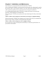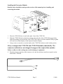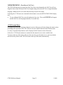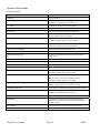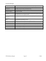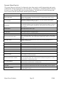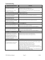
1
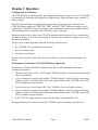
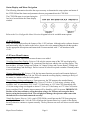
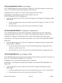
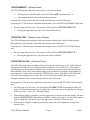
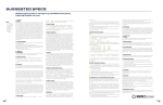
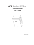
CTSP-EM Series Electronics Modules TSP Universal Electronics Module with v3.xx Software User Manual Myers Power Products CTSP-EM Manual Doc# 990-5500 1/2009 Chapter 1 General Information This Myers Power Products, Inc. (Myers) CTSP Electronics Module (CTSP-EM) with v3.XX software is compatible with all CTSP Transformer Modules (CTSP-TM). A Myers Electronics Module and a Transformer Module together create a Total System Power (TSP) uninterruptible power supply. Important Safety Instructions – Save These Instructions This Safety Guide contains important instructions that should be followed during installation and maintenance of the Myers equipment and batteries. It is intended for Myers customers who setup, install, relocate, or maintain Myers equipment. Changes and modifications to this unit not expressly approved by Myers Power Products could void the warranty. Failure to observe these warnings may result in serious injury, death or damage to the equipment. ELECTRICAL WARNINGS • Do not work alone under hazardous conditions. • Do not handle any metallic connector before the power has been disconnected. • Servicing this equipment may require working with protective covers removed and utility power connected. Use extreme caution during these procedures. • High current through conductive materials could cause severe burns. • When grounding cannot be verified, disconnect the equipment from the utility power outlet before installing or connecting to other equipment. Reconnect the power cord only after all connections are made. • Check that the power cord(s), plug(s), and sockets are in good condition. • Replacement of fuses or other parts must be with identical types and ratings. Substitution of nonidentical parts may cause safety and fire hazards. BATTERY WARNINGS Danger of explosion if battery is incorrectly connected or replaced. Replace batteries with same or equivalent type recommended by the manufacturer. OVERHEAD WARNINGS Never stand below anything while it is being hoisted. Always wear a hard hat. LIFTING WARNINGS Transformer modules are heavy. Use proper lifting techniques and equipment to avoid injury. CTSP-EM Series Manual Page 1 1/2009 Unpacking Inspect the module upon receipt. Notify the carrier if there is damage. The packaging is recyclable; save it for reuse or dispose of it properly. The package contents include: 9 the CTSP-EM 9 the enclosure interface cable 9 the temperature sensor 9 product documentation Models Supported CTSP Universal Electronics Module 15/22 A, 36/48 VDC CTSP-EM48-1 Specifications Environmental Specifications OPERATING TEMPERATURE HUMIDITY -40º F to 158º F (-40º C to 70º C) 5% to 95% noncondensing within enclosure Physical Specifications CHARACTERISTIC SPECIFICATION Height 8.125” (20.7 cm) Width 8” (20.3 cm) Depth, includes T-handle 12.25” (31.2 cm) Weight 17.4 lbs (7.9 kg) Electrical Specifications INPUT CHARACTERISTIC INPUT SPECIFICATION Battery Voltage 36 VDC or 48 VDC Battery Cutoff - Default (VDC) 31.5 (36 V), 42 (48 V) OUTPUT CHARACTERISTIC OUTPUT SPECIFICATION Output Voltage Regulation ±5% CTSP Electronics Module Frequency Stability ± 0.1% DC Breaker Series Current and Trip Voltage 90 A, 80 VDC Myers Power Products Page 2 1/2009 Chapter 2 Installation and Maintenance Only trained service personnel should install and maintain the CTSP-EM. Prior to installing the CTSP-EM, an enclosure must be installed, utility line voltage must be routed to the enclosure, and a CTSP-TM must be installed. Local, state, federal and/or National Electric Code (NEC) regulations regarding location, permits and electrical wiring must be adhered to. It is recommended that optional Myers CTSP-SP’s be added to this system for increased surge protection. Consult with Myers for ordering details. Before placing the CTSP-EM on the enclosure shelf, ensure that the input AC utility circuit breaker is OFF. Failure to adhere to this warning may result in death, serious injury or equipment damage. When positioning the CTSP-EM ensure adequate space for proper airflow. Myers recommends that there be at least 3 inches of clearance on all sides and above the module. Failure to adhere to this warning may result in equipment damage. Do not operate this unit where the temperature and humidity are outside the specified limits. See Specifications in this manual. CTSP-EM Series Manual Page 3 1/2009 Installing Batteries The battery circuit breaker must be OFF or the battery cable must be unplugged from the CTSP-EM prior to battery installation. Although the temperature sensor can be installed on any battery post, it should be attached to terminals of a battery located in the middle of a string (Step 5 below). In the 48V string shown below, the temp sensor should be attached to a terminal on the #2 or #3 batteries. For the 36V string, the temp sensor should be attached to a terminal on the #2 battery. The following figures show basic battery string configurations. 48VDC BATTERY STRING EXAMPLE* Negative output lead to connected equipment Positive output lead to connected equipment *Note: Battery arrangement in the enclosure may differ. 36VDC BATTERY STRING EXAMPLE* Negative output lead to connected equipment Positive output lead to connected equipment *Note: Battery arrangement in the enclosure may differ. Myers Power Products Page 4 1/2009 Installing the Electronics Module Read the entire installation and operation section of this manual prior to installing and connecting the module. 1. Place the CTSP-EM close to and to the right - front of the CTSP-TM. 2. Slide the CTSP-EM back so that the mounting tab on the side of the CTSP-EM engage firmly with the mounting slots on the side of the CTSP-TM. Failure to lock the modules firmly together will result in an alarm display on the Operator Interface Display. 3. Using a coin or screwdriver, turn the latch on the CTSP-TM clockwise to the locked position. Always transport the CTSP-TM and CTSP-EM modules individually. The connector and latch are not designed to support the weight of the modules. Failure to adhere to this warning may result in damage to equipment. 4. Plug the enclosure interface cable connector (A), into the enclosure interface receptacle on the front of the CTSP-EM. A B C D CTSP-EM Series Manual Page 5 1/2009 Depending on the enclosure configuration, connect the following: B -power supply status indicator lamp connector C -enclosure tamper switch connector D -battery temperature sensor probe connector • The requirement when using two CTSP systems in one cabinet is to utilize both temperature probes. One probe connected to each CTSP-EM. Adequate isolation exists so that the probes can be connected to the same battery terminal. Any modification of the system wiring (connecting one temperature probe to more than one CTSP-EM), can cause irreparable damage to the CTSP-EM. 5. Where applicable, plug the CTSP-SM* status monitoring option into the CTSP-EM. Refer to the User Manual for the CTSP-SM* option used. 6. Plug the battery cable into the battery connector on the front of the CTSP-EM. 7. Switch the utility circuit breaker ON. If the unit fails to respond wait one minute, then switch the utility circuit breaker OFF and ON again. 5. Switch the battery circuit breaker ON. 6. Verify operation. Refer to Chapter 3 Operation, in this manual. 7. Close and secure the enclosure. Myers Power Products Page 6 1/2009 Chapter 3 Operation Configuration Verification The CTSP-EM will test and display the unit configuration during power-up or reset. The CTSP-EM will automatically determine and display the configured utility input and output range, and the DC battery voltage. Once the utility and battery circuit breakers are switched ON, three messages will flash in the CTSP-EM display window, AC TEST, DC TEST, and OUT TEST. When the testing process is complete the CTSP-EM will begin scrolling the unit configuration in the message display window. This information will be repeated if the CTSP-EM is reset or restarted. During initial power-up or after a new CTSP-TM installation the unit may ask you to confirm that the installed battery is 36 or 48 volts as displayed. Press the left or right arrow respectively to verify the battery installation. The user can cold start the module when the following conditions exist: 9 the CTSP-EM is not on standby mode operation 9 there is no utility power 9 the batteries are charged Refer to Setup/Cold Start in the Status Display and Menu Navigation section of this manual for details. Performance Verification of CTSP-EM Battery Operation Performance verification should be performed at the time of initial installation and at least semiannually thereafter. 1. Perform a visual check of the CTSP-TM and CTSP-EM modules. Verify that the status indicator lamp is not blinking. 2. Using a voltmeter or visually observing the CTSP-EM Display, verify the voltage at the output connector on the CTSP-TM module. Refer to the attached label on the CTSP-TM or the CTSPTM User Manual for specifications. 3. Turn the utility line circuit breaker OFF. The CTSP-EM will go on Standby operation. 4. Using a voltmeter or visually observing the CTSP-EM Display, verify the voltage at the output connector on the CTSP-TM module. Refer to the attached label on the CTSP-TM or the CTSPTM User Manual for specifications. 5. If the CTSP-TM voltage output is correct, turn the utility line circuit breaker ON. Wait approximately 20 seconds to ensure the CTSP-EM system is operating on utility power. CTSP-EM Series Manual Page 7 1/2009 Status Display and Menu Navigation The following information describes the steps necessary to determine the setup options and status of the CTSP-EM and the alarms and parameters that are programmed into the CTSP-EM. The CTSP-EM menu is navigated using the four keys located below the status display window. Refer to the User Configurable Menu Selections diagram below for available menu options. v3.XX Software Note: The following describes the features of the v3.XX software. Although earlier software features and functionality may be similar to the below, please refer to the manuals shipped with that product for the appropriate descriptions and instructions. Features marked with “*” are introduced with v3.00. v3.XX non-Menu Features Starting with v3.00, important non-menu features were added. *Scrolling Status/Data Display: Prior to v3.00 only the current status of the TSP was displayed by the CTSP-EM. Introduced with v3.00, operational data has been added to the scrolling display. This data includes: AC Input Voltage and Current, AC Output Voltage and Current, Battery Voltage and Current (both charge and discharge). Earlier versions of software required a number of button-pushes to access this data. *Restart Menu when Idle: Prior to v3.00, the last menu function accessed would remain displayed indefinitely. Introduced with v3.00, the TSP will restart the scrolling display, returning to the top of the menu, two minutes after the last keystroke. *Lower Battery Voltage on Repower: Upon power-up, the TSP measures the attached battery string(s) and does not connect “bad” strings. Prior to v3.00 for a 36 Volt strings, a battery string would be “bad” if it was below 22.5 Volts (7.5 Volts/battery or 1.25 Volts/Cell). Introduced with v3.00, the string voltage can degrade to about 13 Volts (4.3 Volts/battery or 0.72 Volts/Cell) before being considered “bad”. Similar improvements will be found for a 48 Volt system. IMPORTANT: Because of the lowered battery string detection voltage, the TSP may not recognize that a battery string has been mis-wired. To avoid physical damage, the operator must ensure that the batteries are wired and connected correctly! *Stuck Key Ignore: Prior to v3.00, a stuck CTSP-EM key would prevent the TSP from going into standby. Introduced with v3.00, the TSP will inform the operator that a key is stuck via the display but will otherwise continue to operate normally. The keys that are not stuck will also access the menu normally. Myers Power Products Page 8 1/2009 v3.XX Setup Menu Note: Unless otherwise noted, commands and selections made through the menu system are performed immediately after selection. SETUP/CANADDR (CAN Bus Address) The CTSP-EM communicates to its peripherals (such as the CTSP-SM* modules) via a CAN bus architecture. In certain configurations, multiple TSP’s may be connected together sharing the same CAN bus. In those configurations, each CTSP-EM module must be configured to be a different CAN bus address. The CTSP-EM address MUST match the address of the CTSP-SM5 or CTSP-SM8 module for the two devices to communicate to each other. If the CTSP-EM address does need to be changed, it is accessible from the Setup section of the menu. Following the v3.XX menu tree contained in this manual, access the SETUP/CANADDR/UNIT# display and; • • Use the up and down arrow keys to select the desired CTSP-EM CAN address. Default is 1. • Press the right arrow key to save and store the selected address. To initiate the above address change the system must be reset. Simultaneously press the left and down arrow keys; SW RESET will appear in the display window and the reset process will begin. NOTE: If a Software Reset is performed during Standby Operation, power to connected equipment will be interrupted. Refer to Troubleshooting in this manual. SETUP/CHARGER/METHOD (Charge Method) The CTSP-EM supports both Cycle and Float Charge modes. Default is Float. Cycle Charge Mode: This mode allows the CTSP-EM to reduce the battery float voltage for 24 hours after every 48 hours of float charge operation. Float Charge Mode: This mode charges and maintains the batteries using default settings at 13.5 V per battery at 25° C. Selection of the Charge Mode is made from the Setup section of the menu. Following the v3.XX menu tree contained in this manual, access the SETUP/CHARGER/METHOD display and; • Press the right arrow key once. The active charger mode will appear in the display window, CYCLE > or FLOAT >. • Use the up and down arrow keys to select the desired CTSP-EM charger mode. • Press the right arrow key to save and store the selected charger mode. CTSP-EM Series Manual Page 9 1/2009 *SETUP/CHARGER/VOLTAGE (Float Voltage) The CTSP-EM supports user setup of the Float Voltage level. The Float Voltage level can be set at 2.20 to 2.35 Volts/Cell in 10mV steps. Default is 2.25 Volts/Cell. Changing the Float Voltage level is made from the Setup section of the menu. Following the v3.XX menu tree contained in this manual, access the SETUP/CHARGER/VOLTAGE display and; • Press the right arrow key once. The active Float Voltage level will appear in the display window, VPC 2.XX >. • Use the up and down arrow keys to select the desired Float Voltage level, 2.00 to 2.35 VPC (Volts per Cell). • Press the right arrow key to save and store the selected Float Voltage. *SETUP/CHARGER/TEMPCO (Temperature Compensation) The CTSP-EM supports user setup of the Temperature Compensation slope. The Temperature Compensations slope can be set at -5 to -2 mV/ºC/Cell in 500uV steps. Default is -5 mV/ºC/Cell. Changing the Temperature Compensation slope is made from the Setup section of the menu. Following the v3.XX menu tree contained in this manual, access the SETUP/CHARGER/TEMPCO display and; • Press the right arrow key once. The active Temperature Compensation slope will appear in the display window, -.00XX V >. • Use the up and down arrow keys to select the desired Temperature Compensation slope, -0.0050 to -0.0020 Volts/ºC/Cell. • Press the right arrow key to save and store the selected Temperature Compensation slope. *SETUP/CHARGER/LVCO (Low Voltage Cut-Off) The CTSP-EM supports user setup of the Low Voltage Cut-Off (LVCO) point. The LVCO can be set from 1.70 to 1.80 Volts/Cell. Default is 1.75 Volts/Cell. Changing the LVCO is made from the Setup section of the menu. Following the v3.XX menu tree contained in this manual, access the SETUP/CHARGER/LVCO display and; • Press the right arrow key once. The active LVCO point will appear in the display window, VPC 1.XX >. • Use the up and down arrow keys to select the desired LVCO point, 1.70 to 1.80 Volts/Cell. • Press the right arrow key to save and store the selected LVCO point. Myers Power Products Page 10 1/2009 SETUP/COLDSTRT (Cold Start) Use of the Cold Start feature will allow an operator to force the TSP into Standby operation immediately after power up or reset in the event of bad or missing AC utility voltage. • During power up or reset, the CTSP-EM performs a series of verification tests. While battery verification is being tested CHECKING BATTERY – STANDBY INHIBIT will appear in the display window on the CTSP-EM. Standby operation cannot commence until the batteries have been verified. If the CTSP-EM detects an unacceptable utility power level, and system configuration has been previously established, BAD AC IN – STANDBY INHIBIT will appear in the CTSP-EM display window. Cold Start can be used to override the TSP, to placing it into Standby operation. Use of the Cold Start feature is made from the Setup section of the menu. Following the v3.XX menu tree contained in this manual, access the SETUP/COLDSTRT display and; • Press the right arrow key once. EXECUTE > appears in the display window. • Press the right arrow key again to execute a cold start. VERIFIED appears in the display window and standby operation will begin immediately. Note: Standby operation from Cold Start will only occur when “Bad AC In – Standby Inhibit” is displayed. SETUP/OVERLOAD (Overload Protection) The CTSP-EM supports user configured output overload protection. Selections are based on a cycle of 10 seconds (10%), to 100 seconds (100%) for every 100 seconds of runtime. The CTSP-EM default setting for the output overload cycle is 100%. This effectively disables output overload protection. Use of the Overload Protection feature is made from the Setup section of the menu. Following the v3.XX menu tree contained in this manual, access the SETUP/OVERLOAD display and; Press the right arrow key once. OCP 100> appears in the display window. Use the up and down arrow keys to select the desired overload protection cycle. Press the right arrow key to save and store the selection. NOTE: Activation of overload protection begins 255 seconds following an overload situation. If the battery weakens to less than 11.4 V per battery and overload protection is enabled, the cycle will become fixed at 9 seconds on and 591 seconds off. CTSP-EM Series Manual Page 11 1/2009 SETUP/EVENTS (Event Tracking) The CTSP-EM will record the occurrence of “events” by amount and duration. An “event” can be selectively defined to be; • *Loss of AC Line voltage, or, • When the TSP goes into Standby operation As a TSP can be put into Standby operation via operations like Self-Test, the number and duration of AC Line voltage loss may not match the number of times and duration of Standby operation. Selection of either AC Line loss or Standby Operation as an Event is made from the Setup section of the menu. Following the v3.XX menu tree contained in this manual, access the SETUP/EVENTS display and; • Press the right arrow key once. The active mode will appear in the display window, LINE > or STANDBY >. • Use the up and down arrow keys to select the desired CTSP-EM Event mode. • Press the right arrow key to save and store the selected Event mode. *SETUP/RMSMODE (AC Mains Sensitivity) The CTSP-EM digitizes and monitors each cycle the incoming AC Line waveform. The TSP will react to AC Line disturbances of fractions of a cycle in length, allowing the TSP to be able to respond quickly, going to Standby Operation when the AC Line voltage degrades. If the incoming AC Line voltage waveform is very “dirty”, the TSP will disqualify the AC Line voltage and switch into Standby Operation and remain there until the batteries fully discharge, even though there is useable AC Line voltage at the input to the TSP. An example is when an AC generator is used to power the TSP. Sometimes the generator can throw “spikes” or other abnormalities into the AC waveform, causing the TSP to go into Standby Operation inadvertently. The CTSP-EM can be placed either temporarily or permanently into a period of reduced AC Mains Sensitivity where the TSP only monitors and qualifies the incoming AC Line voltage by the average RMS voltage and average frequency thresholds. The TSP will then ignore voltage spikes on the AC Line voltage. Modifying the AC Mains Sensitivity is made from the Setup section of the menu. Following the v3.XX menu tree contained in this manual, access the SETUP/RMSMODE display and; Press the right arrow key once. The active mode will appear in the display window. The display may read, ON/OFF or a period of 10MIN, 1HR, 1DAY, 1 – 6 WEEKS >. Default is OFF. Use the up and down arrow keys to select the desired CTSP-EM AC Mains Sensitivity. If this mode is being selected due to generator use, select the period of time the generator is expected to be online. The CTSP-EM will turn RMSMODE to Off after the selected time has expired. If the cause of the AC Line disturbances is fairly permanent, then the ON selection may be the correct selection. Press the right arrow key to save and store the selected AC Mains Sensitivity mode. Myers Power Products Page 12 1/2009 *SETUP/SWRESET (Software Reset) The CTSP-EM software/firmware can be reset by one of two methods; • Pressing the two outside buttons on the CTSP-EM (◄▼) simultaneously, or, • Activating the Software Reset function from the menu Activating the Software Reset function is made from the Setup section of the menu. Following the v3.XX menu tree contained in this manual, access the SETUP/SWRESET display and; • Press the right arrow key once. The operator will be asked to CONFIRM EXECUTE >. • Pressing the right arrow key will execute the Software Reset. *SETUP/FACTORY (Restore Factory Defaults) The CTSP-EM supports restoring the software/firmware settings to the Factory Default settings. Restoring the Factory Defaults is made from the Setup section of the menu. Following the v3.XX menu tree contained in this manual, access the SETUP/FACTORY display and; • Press the right arrow key once. The operator will be asked to CONFIRM EXECUTE >. • Pressing the right arrow key will restore the Factory Defaults. *SETUP/TEST/CLOCK (Set Internal Clock) The CTSP-EM will perform a monthly self-test. If the internal clock is not set, the CTSP-EM will still perform a monthly self-test, starting with the default time of 12:00AM, Jan 1, 2000 which is loaded upon power up. Setting the internal clock will allow the self-test to start and stop at known times and dates. Note: There is an internal supply to the clock that will keep the clock running for approximately 12 hours in the event that the CTSP-EM loses power. Should the CTSP-EM not be powered for an extended period of time, the clock will start at the default date at power up. Setting the Internal Clock is made from the Setup section of the menu. Following the v3.XX menu tree contained in this manual, access the SETUP/TEST/CLOCK display and; • Press the right arrow key once. The date display DD:MMM:YY:DS (day:month:year:DS) will appear. Use the up/down arrow keys to change the value shown, press the right arrow to advance to the next value. Note: DS = Daylight Savings. • When the date display is complete, press the right arrow to advance to the time display. The time display HR:MN:A/P:DAY (hour:minutes:AM/PM:weekday) will appear. Use the up/down arrow keys to change the value shown, press the right arrow to advance to the next value. • When the time display is complete, pressing the right arrow will complete the setting of the Internal Clock. CTSP-EM Series Manual Page 13 1/2009 *SETUP/TEST/AUTO (Set Time of Auto Self-Test) The CTSP-EM supports user setup of the Auto Self-Test time/date. The Auto Self-Test time/date can be set to any time or weekday. The default time/date is: 10AM/Wednesday. The CTSP-EM will execute the Auto Self-Test on the first weekday specified in any month. Setting the Auto Self-Test time and day is made from the Setup section of the menu. Following the v3.XX menu tree contained in this manual, access the SETUP/TEST/AUTO display and; • Press the right arrow key once. The display HR:MIN:A/P:DAY (hour:minutes:AM/PM:weekday) will appear. Use the up/down arrow keys to change the value shown, press the right arrow to advance to the next value. Note: When the weekday is set to “---“, Auto Self-Test is disabled. • When the display is complete, pressing the right arrow will complete the setting of the Auto Self Test time and day. *SETUP/TEST/LENGTH (Self-Test Length) The CTSP-EM supports user setup of the length of Self-Test. The Self-Test Lengths that can be selected are: 1, 5, 10, 15, 30 and 60 minutes. The default Self-Test Length is: 5 minutes. Setting the Self-Test Length is made from the Setup section of the menu. Following the v3.XX menu tree contained in this manual, access the SETUP/TEST/LENGTH display and; • Press the right arrow key once. The active Self-Test Length will appear in the display. • Use the up and down arrow keys to select the desired Self-Test Length. • When the display is complete, pressing the right arrow will complete the setting of the Self-Test Length. *SETUP/TEST/RUN (Start Manual Self-Test) The CTSP-EM supports user start of the Self-Test. Once started manually, the Self-Test will run length of time as specified by the Self-Test Length setting unless the Self-Test is stopped manually. Starting a Manual Self-Test is made from the Setup section of the menu. Following the v3.XX menu tree contained in this manual, access the SETUP/TEST/RUN display and; • To initiate Manual Self-Test, press the right arrow key once. Self-Test will begin immediately and the word VERIFIED will appear. The Self-Test will run the period of time specified by the Self-Test Length unless stopped manually. Myers Power Products Page 14 1/2009 *SETUP/TEST/STOP (Stop Manual Self-Test) The CTSP-EM supports user stop of the Self-Test. Once started manually, the Self-Test will run length of time as specified by the Self-Test Length setting unless the Self-Test is stopped manually. Stopping a Manual Self-Test is made from the Setup section of the menu. Following the v3.XX menu tree contained in this manual, access the SETUP/TEST/STOP display and; • To stop a Manual Self-Test, press the right arrow key once. The word VERIFIED will appear and the Self-Test will stop approximately 15 seconds later. v3.XX Params Menu Accessing any item in the Parameter (Params) section of the menu will only display the status or data pertaining to the operation of the TSP. There are no user settable functions in the Params menu. A variety of operational parameters can be displayed in the Params section of the menu. Follow the v3.XX Params menu tree contained in this manual to access the available data. To return to the top of the menu, either use the arrow keys per the menu tree or wait two minutes after the last key stroke as the TSP will return to the top of the menu automatically. CTSP-EM Series Manual Page 15 1/2009 v3.XX Software Setup Menu Tree TSP by Myers v3.XX (Dynamic Status Display) CANADDR UNIT # ► (▲▼ Selects #, ► Stores) Default = 1 ◄► ▲▼ ▲▼ ▲▼ METHOD ◄► FLOAT or CYCLE (▲▼ Selects, ► Stores) Default = Float ◄► *VPC 2.10 to 2.35 (▲▼ Selects, ► Stores) Default = 2.25 ◄► *-.0020 to -.0050V (▲▼ Selects, ► Stores) Default = -.0050 ◄► *1.70 to 1.80V (▲▼ Selects, ► Stores) Default = 1.75 CHARGER ▲▼ ▲▼ SETUP *VOLTAGE (Float Voltage / Cell) ◄► ◄► ▲▼ ▲▼ *TEMPCO (Temp Compensation in V/Cell/°C) ▲▼ PARAMS ▲▼ ▲▼ *LVCO (Low Voltage Cut-Off in Volts/Cell) ◄► See “Params” Menu Page ▲▼ COLDSTRT ◄► EXECUTE ► (► Executes) ◄► OCP ## ► (▲▼ Selects, ► Stores) ◄► *LINE or STANDBY (▲▼ Selects, ► Stores) ▲▼ OVERLOAD ▲▼ EVENTS ▲▼ *RMSMODE (Reduced AC Mains Sensitivity) ◄► *ON/OFF or period of 10MIN/1HR/1DAY/1 – 6 WEEKS (▲▼ Selects, ► Stores) ▲▼ *SWRESET (Resets Program) *CONFIRM EXECUTE ► (► Executes) ◄► ▲▼ *FACTORY (Restores Factory Defaults) *CONFIRM EXECUTE ► (► Executes) ◄► ▲▼ *TEST *CLOCK Format: DD:MMM:YY:DS HR:MN:A/P:DAY ◄► *Example: 13:JUL:08:DS 11:59:A:SUN (▲▼ Selects, ► Stores) ◄► *Example: 11:59:A:SUN (▲▼ Selects, ► Stores) ◄► *1/5/10/15/30/60MIN (▲▼ Selects, ► Stores) ◄► *EXECUTE ► (► Executes) ◄► *EXECUTE ► (► Executes) DS=Daylight Savings ◄► * denotes features/ functions new to v3.XX Software ▲▼ *AUTO (Set Time of Monthly Test) ▲▼ ▲▼ *LENGTH (Duration of Monthly Test) ▲▼ *RUN (Starts Test Manually) ▲▼ *STOP (Stops Test Manually) Myers Power Products Page 16 1/2009 v3.XX Software Parameter Menu Tree TSP by Myers v3.XX (Dynamic Status Display) INPUT ▲▼ ▲▼ ▲▼ ◄► INPUT ###.# VAC (AC Input in Volts RMS) INPUT ###.# IAC (AC Input Current in Amps RMS) ▲▼ INPUT ###.# KW (AC Input Power in KiloWatts Average) SETUP INPUT ###.# HZ See “Setup” Menu Page ◄► ▲▼ ▲▼ OUTPUT ◄► PARAMS OUTPUT ###.# VAC (AC Output in Volts RMS) OUTPUT ###.# IAC (AC Output Current in Amps RMS) ▲▼ ◄► OUTPUT ###.# KW (AC Output Power in KiloWatts) ▲▼ ▲▼ BATTERY ◄► BATTERY ###.# VDC (Battery String Voltage DC) BATTERY ###.# IDC (Battery String Current DC) ▲▼ ▲▼ TEMP ◄► HEAT SINK ###.# C (Heat Sink Temperature) EXTERNAL A ###.# C (Batt Temp Sensor) ▲▼ EXTERNAL B ###.# C (Batt Temp Sensor, if present) EXTERNAL C ###.# C (Batt Temp Sensor, if present) ▲▼ EVENTS ◄► ### EVENTS (Reboot EM to Clear) ### MINUTES (Reboot EM to Clear) ▲▼ ▲▼ STATUS ◄► ▲▼ ▲▼ CONFIG CTSP-EM Series Manual DISPLAYS CURRENT STATUS FLAGS ◄► Page 17 DISPLAYS CURRENT UNIT CONFIG 1/2009 Dynamic Status Display Status messages: STATUS MESSAGE MEANING NORMAL Normal operation NORMAL CHARGING -Normal operation, and, -the battery is charging at greater than 0.8 A. AC TEST CTSP-EM is checking the AC configuration DC TEST CTSP-EM is checking the DC configuration OUT TEST CTSP-EM is checking the Output configuration VERIFIED CTSP-EM has verified the system configuration, or the selected command has been accepted CHECKING BATTERY – STANDBY INHIBIT -System is checking the batteries -Automatic standby operation is not available BAD AC IN – STANDBY INHIBIT -Utility power input is unacceptable or absent -Automatic standby operation is not available ON STANBY TRANSFER Transferring from standby to utility power ON STANDBY SELF TEST Manual or automatic Self Test in progress ON STANDBY AC FAIL Standby is enabled due to unacceptable or absent utility power input ALARM COM BUS FAILURE Unable to communicate due to bus failure (repair bus) ALARM ADDRESS CONFLICT Two or more CTSP-EM modules have the same address ALARM STANDBY INHIBIT Automatic Standby operation is not available ALARM HIGH TEMP Standby is unavailable due to high heat sink temperature ALARM HIGH BATTERY -Battery voltage is too high for present configuration -Automatic standby operation not available ALARM DEAD BATTERY -Battery voltage is too low to reliably support standby -Battery voltage is low, unit is recharging batteries -Automatic standby operation not available ALARM NO BATTERY -Battery has unacceptably low voltage -Battery is disconnected or circuit breaker is OFF ALARM OVERLOAD Output current exceeds the specified rating for the CTSP-TM ALARM LOCK OPEN -Close module Interlock -Standby is unavailable when lock is open ALARM BAD TM RELAY Replace the Transformer Module SLEEPING Displayed every 60 seconds while unit is without utility power and system has been shut-down after reaching Low Voltage Cut-Off. SHUTDOWN Displayed momentarily before entering sleep mode POWER UP Displayed momentarily when returning from sleep mode Myers Power Products Page 18 1/2009 Firmware Messages Bad AC In Input is too low (<100 VAC) or frequency is too far off for input range determination Bad AC Out The output is less than 50 volts RMS. CTSP-TM output tap selector may be disconnected Confirm 36V< If the battery string is 36 VDC, press the left arrow key Confirm >48V If the battery string is 48 VDC, press the right arrow key EM/TM Incompatible Upgrade the CTSP-EM Unrecognized EM Upgrade the CTSP-EM 49400-49463 The installed firmware revision does not support the installed hardware. Replace CTSP-EM module with later revision or upgrade Firmware. 49500-49554 50630-50664 50520-50534 Personality Card EEPROM is failed or initialized incorrectly – replace CTSP-EM. 50610 -Transfer Module ID Checksum is incorrect -Replacement of either the CTSP-TM or the CTSP-EM is necessary 50620 Transformer Module ID Missing or Incorrect (replace CTSP-TM). 50510 CTSP-EM Module Revision is Incompatible with attached Transformer Module. STUCK KEY 1 The number 1(down arrow) keypad button on the CTSP-EM is stuck (closed) STUCK KEY 2 The number 2 (up arrow) keypad button on the CTSP-EM is stuck (closed) STUCK KEY 3 The number 3 (right arrow) keypad button on the CTSP-EM is stuck (closed) STUCK KEY 4 The number 4 (left arrow) keypad button on the CTSP-EM is stuck (closed) CTSP-EM Series Manual Page 19 1/2009 Dynamic Status Flag List The system flags are useful only for diagnostics since they require careful interpretation and certain combinations of flags might appear to be contradictory. The display is continually updated with only the active (or true) system flags in the list being displayed. The table below lists the messages that may be observed in the status display and their general meaning. FLAG MEANING DEAD BATTERY The battery is too weak to attempt standby operation. This state is always true at system reset, and will be cleared if the charger is enabled and the battery string is above 1.9 volts per cell. NO BATTERY The battery is absent or below 0.72 volts per cell. This could also mean that the battery circuit breaker or wiring is open. SLEEPING The battery is depleted and the unit is entering sleep mode. (Note: this message will be displayed regardless of the user interface location). When the battery or AC power recovers, the unit will display “POWER UP” momentarily before returning to the user interface. DOOR OPEN The tamper alarm circuit is open. CHARGING The battery charger is enabled to charge the batteries. LOCK OPEN The module interlock is unlatched (open). HIGH BATTERY The battery voltage is above acceptable limits. (2.6V per cell). RELAY TEST FAIL OPEN The CTSP-TM module relay armature is in the de-energized position, but should be in the energized position. This could indicate welded relay contacts or an open relay circuit. COM BUS FAIL CTSP is unable to communicate due to bus errors preventing transmission or reception of valid data. STANDBY INHIBIT Standby operation is inhibited. LOW OUTPUT Indicates the output is below approximately 25 V rms. ON STANDBY Unit is in standby mode. ADDRESS CONFLICT More than one CTSP is attempting to claim the same CAN bus address. AC FAIL Mains voltage or frequency is outside of operating limits. OVERLOAD CTSP detects an output current overload. SOFT AC LINE Mains impedance appears to be abnormally high and at least one attempt to transfer from standby to mains was aborted. RELAY TEST FAIL CLOSED The CTSP-TM module relay armature is in the energized position, but should be in the de-energized position. This could indicate a mechanical relay failure or a relay contact failure or a shorted relay driver. AC LINE INHIBIT Operation from AC input is inhibited. This does not necessarily mean that the AC line has failed or that the TSP is in standby mode. INITIALIZING The unit is powered from mains. This can occur even if mains are inhibited. ON LINE Unit is in power-on self test mode. This also occurs if the battery circuit is opened. CHARGER INHIBIT Battery charging is not enabled. Causes could be temperature or bad AC line or missing/defective battery. Myers Power Products Page 20 1/2009 Troubleshooting PROBLEM AND POSSIBLE CAUSE SOLUTION CTSP-EM WILL NOT TURN ON Utility power is not connected. -Check that the utility circuit breaker is ON. -Check that the utility power cable is fully engaged. Having performed the above, and the CTSP-EM is not responding: -Switch the battery circuit breaker OFF. Wait five seconds and switch the battery circuit breaker ON. UTILITY POWER FAILS AND STANDBY MODE OPERATION DOES NOT START If the utility power fails and the CTSP-EM is not ON, power to all connected equipment will be interrupted. -Reestablish utility power connection. -A Cold Start may be initiated to start standby mode operation. SOFTWARE RESET IS INITIATED DURING STANDBY MODE OPERATION If the system is on standby power and a software reset is initiated, the CTSP-EM will shutdown and power to all connected equipment will be interrupted. -Reestablish a utility power connection. -A Cold Start may be initiated to restart standby mode function. AT INITIAL STARTUP CTSP-EM DISPLAY WINDOW READS BAD AC IN The CTSP-TM is operating with incorrect utility input voltage and/or frequency. -Check the specifications on the label attached to the CTSP-TM or refer to Specifications in the CTSP-TM User Manual. -Check that the CTSP-TM output voltage Tap is connected properly. AT INITIAL STARTUP CTSP-EM DISPLAY WINDOW READS BAD AC OUT The CTSP-TM is operating with incorrect utility input voltage and/or frequency. -Check the specifications on the label attached to the CTSP-TM or refer to Specifications in the CTSP-TM User Manual. -Check that the CTSP-TM output voltage Tap is connected properly. CTSP-EM DISPLAY WINDOW READS CONFIRM 36V Normal operation. At initial startup for a new CTSP-TM installation, the CTSP system may see a fully charged three battery string as a discharged four battery string. The CTSP system will request confirmation on the correct battery configuration. -If the battery string is 36 VDC, press the left arrow key -If the battery string is 48 VDC, press the right arrow key CTSP-EM DISPLAY WINDOW READS ALARM NO BATTERY The batteries are connected to the CTSPEM. The CTSP-EM display window indicates that battery connections are missing. CTSP-EM Series Manual -Check that the battery circuit breaker is ON. -Check that the battery cable connector on the CTSP-EM is fully engaged. -Check the battery terminals are free from corrosion. -Check that the battery terminal connections are secure. -Check battery voltage as measured by the CTSP-EM. Refer to the User Configuration Menu Selections diagram in this manual. Voltage readings below 21.5 V (three battery string), 30 V (four battery string) indicate severely discharged batteries. Replace batteries with voltage readings below 7.5 V. The CTSP-EM will not recharge batteries with very low voltage readings. Page 21 1/2009 Chapter 4 Service, Contact and Warranty Information Service Myers Power Products makes every effort to ensure parts and equipment arrives in working condition. Occasionally, it may be necessary to return parts or equipment that is not in working condition. If the unit requires service do not return it to the dealer. Follow these steps: 1. 2. Contact Myers Customer Service by telephone at (610) 868-3500 Monday - Friday 8AM to 5PM U.S. Eastern time. Note the product model number, the serial number, and the date purchased. If you call Myers Customer Service, a technician may ask you to describe the problem and try to solve it over the phone. If this is not possible the technician may issue a Returned Material Authorization Number (RMA#). If the product is under warranty, repairs are free. If not, there is a repair charge. Procedures for servicing or returning products may vary internationally. Contact Myers Power Products for country specific instructions. Pack the product well, preferably in its original packaging. Pack the unit properly to avoid damage in transit. Never use Styrofoam beads for packaging as the static electricity that is generated may damage electronics. Damage sustained in transit is not covered under warranty. 3. Mark the RMA# on the outside of the package. 4. Return the unit by insured, prepaid carrier to the address given to you by Customer Service. Be sure to deliver spent batteries to a recycling facility or ship to the manufacturer in the replacement battery packing material. Myers Power Products contact information: For Customer Service… Mailing/Shipping Address… Telephone: (610) 868-3500 Monday – Friday 8AM to 5PM US Eastern Myers Power Products, Inc. 2000 Highland Ave. Bethlehem, PA 18020 Myers Power Products Page 22 1/2009 Limited Warranty Myers Power Products, Inc. (Myers) warrants this product to be free from defects in materials and workmanship for a period of five years from the date of purchase. Its obligation under this warranty is limited to repairing or replacing, at its own sole option, any such defective products. To obtain service under warranty you must obtain a Returned Material Authorization (RMA) number from customer support. Products must be returned with transportation charges prepaid and should be accompanied by a brief description of the problem encountered and proof of date of purchase. This warranty does not apply to equipment that has been damaged by accident, negligence, or misapplication or has been altered or modified in any way. This warranty applies only to the original purchaser. EXCEPT AS PROVIDED HEREIN, MYERS MAKES NO WARRANTIES, EXPRESSED OR IMPLIED, INCLUDING WARRANTIES OF MERCHANTABILITY AND FITNESS FOR A PARTICULAR PURPOSE. Some states do not permit limitation or exclusion of implied warranties; therefore, the aforesaid limitation(s) or exclusion(s) may not apply to the purchaser. EXCEPT AS PROVIDED ABOVE, IN NO EVENT WILL MYERS BE LIABLE FOR DIRECT, INDIRECT, SPECIAL, INCIDENTAL, OR CONSEQUENTIAL DAMAGES ARISING OUT OF THE USE OF THIS PRODUCT, EVEN IF ADVISED OF THE POSSIBILITY OF SUCH DAMAGE. Specifically, Myers is not liable for any costs, such as lost profits or revenue, loss of equipment, loss of use of equipment, loss of software, loss of data, costs of substitutes, claims by third parties, or otherwise. Entire contents copyright © 2008 by Myers Power Products, Inc.. All rights reserved. Reproduction in whole or in part without permission is prohibited. CTSP-EM Series Manual Page 23 1/2009