1
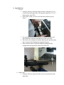
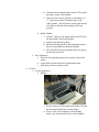
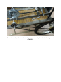
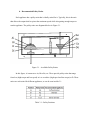
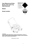
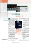
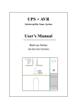
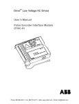
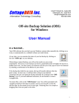
Pretty good overall, & good balance
of images & text instructions.
Good initial checklist & parts
list. Some additional warnings
could have been included.
Human Power Take Off
Owner’s Manual
A.How to Operate the System
WARNING:
The power take off (PTO) unit is capable of achieving speeds up to 2000 RPM.
It is essential that whenever the system is in use, the user and onlookers keep
hands, hair, clothing, and any accessories clear from moving parts.
Failure to do so will result in serious injury.
1.
Basic Use Checklist
a. To properly set up the system for usage, the following items will be needed:
i.
PTO/ Vertical Adaptor (if needed)
ii. Input source (Bicycle and Healthy Human Preferred)
iii. Bicycle Stand
iv.
Master Linked Bicycle Chain (50”)
v.
Mounting Board
vi.
C-Clamps for Mounting
vii.
Tools:
1. Wrench
2. Allen Keys (ANSI)
2. Basic Set-Up/Assembly
a. Mounting
i. First clamp the mounting board down to the table that the PTO will be
operating on with the supplied C-clamps (3).
1. Tighten clamps down as tight as possible using your hands only.
2. For best performance set the PTO long ways with the table so that
the bike will be facing out from the end.
ii. Screw the PTO into the mounting board with the 1/4” thumb screws in the
desired location. Again, tighten down the thumb screws as snug as
possible through hand tightening. The tensioning handle side (input side)
of the PTO needs to be on the edge of the table in order to function.
1. The different mounting locations are so that other appliances can
be hooked up to it. The middle location is the main position for
the vertical adaptor and coffee grinder.
Figure 1: Clamp Mounting Board to Table.
Figure 2: Mount PTO with Thumb Screws
b. Input Hook Up
i. Bicycle
1. Using an Allen key attach the input sprocket so that the set screw
is on the flat of the input shaft. The sprocket should be 2.5” to 3.5”
from the side of the PTO.
2. Set the bike so that it is at the end of the table and facing away
from it.
3. For maximum speed the bike should be in top gear and the extra
chain should be wrapped around the larger gear in the back.
4. The chain is also wrapped around the input sprocket and the master
link is connected by bending and snapping into place.
5. Ensure that the chain is tight and straight by pulling the bike
straight and looking down the chain toward the PTO.
ii. Hand crank
1. Using an Allen key torque down the set screw onto the flat of the
input shaft.
iii. Other Inputs (Requires Ingenuity)
1. The PTO has the option for a belt/chain or hand crank input. If
any other device is to be used it must be adapted to the correct size
V-belt or a standard bike chain. Other pulleys with set screws and
a ½” bore can also be used to adapt other belts.
c. Speed vs. Torque
i. The speed/torque of the output depends on two things:
1. The input from the user.
a. This system is designed for a 60 RPM input between 1/4 1/3 Hp.
b. The user should not try to over exert him/herself.
c. The maximum power input should be 1/3 Hp.
2. The pulley ratios.
Table 1: Speed/Torque Pulley Ratios
Speed/Torque
Input Pulley
Output Pulley
High/Low
Largest
Smallest
Medium High/Medium Low
2nd Largest
2nd Smallest
Medium Low/Medium High
3rd Largest
3rd Smallest
Low/High
Smallest
Largest
Speed/Torque Arrangement: Medium Low/Medium High
ii. Changing PTO speeds:
1. Un-tension belt by pulling handle out and turning clockwise.\
2. Open Lid of PTO.
3. Switch belt to desired pulleys based on speed/torque needs and the
above speed/torque table.
d. Appliance Attachment
i. Horizontal
1. Current Appliances
a. Coffee Grinder
i. Attach 2” pulley to the output shaft of the PTO and
the input shaft of the coffee grinder.
ii. Align the pulley from the coffee grinder and the
pulley from the PTO so that they are in line for the
belt.
iii. Wrap the belt around the pulley on the PTO around
the pulley on the coffee grinder.
iv. Once the belt is in line, tension it so that there is a
1.5” gap between the PTO and the base of the
coffee grinder. This will allow for the right amount
of tension so that the coffee grinder can be run
properly.
b. Bench Grinder
i. Attach 2” pulley to the output shaft of the PTO and
the input shaft of the bench grinder.
ii. Slide the belt onto the pulleys.
iii. Mount the bench grinder to the mounting board in
the pre located holes for the bench grinder.
iv. This will allow for proper distance between pulley s
for the belt to be used.
2. New Appliances
a. Look for data regarding input motor’s power, speed, and
torque.
b. Assess shaft location and look for attachment point.
c. Add pulley or hose coupler to shaft.
ii. Vertical
1. Current Appliances
a. Blender
i. Fit the coupler over the output shaft of the PTO and
the horizontal shaft of the vertical adapter.
ii. Screw in the vertical adapter to the mounting
board’s pre located holes for the vertical adapter.
iii. Tighten the coupler to both shafts to a snug fit that
can be achieved by hand tightening.
iv. Place the blender attachment to the vertical part of
the shaft.
2. New Appliances
a. See section for new horizontal appliances.
e. Internal Assembly
i. NOTE: These steps will NOT be done with daily operation of the
PTO. These instructions should be used when the following needs to
be performed:
1. Replacing the belt.
2. Replacing pulleys.
3. Replacing the bearings.
4. Replacing the shafts
ii. Mount the two bearings onto the PTO with the bearings facing the inside
of the unit. One bearing will be used for each shaft.
iii. Insert the 16” shaft into the input shaft side of the unit. This is the side
opposite that of where the pipe belt tensioning roller is. Slide on half of
the shaft. Do not insert it all the way into the bushing side.
1. Slip on a snap ring far enough down the shaft to allow for the
pulleys to be inserted.
2. Slide on the largest conical pulley (6”,5”4”) first with the keying
attachment. The 6” side of the pulley needs to be nearest the
bearing side of the unit.
3. Slide on the 2” pulley and lock it down with the set screw. This
pulley should be flush with the large conical pulley.
4. Slide on another snap ring.
5. DO NOT lock down the shaft at the bearing or with the snap rings.
Leave about 2” or 3” between the end of the shaft and the bushing
side of the PTO.
iv. Insert the 10” shaft into the output side of the unit. This is the side nearest
the pipe belt tensioning roller. Slide on half of the shaft. Do not insert it
all the way into the bushing side.
1. Slip on a snap ring far enough down the shaft to allow for the
pulleys to be inserted.
2. Slide on the 4”, 3”, 2” pulley onto the shaft. Make sure the larger
pulley is on the bearing side of the unit.
3. Slide on the 1.5” pulley.
4. Slide on another snap ring using the snap ring tool.
5. DO NOT lock down the shaft at the bearing or with the snap rings.
Leave about 2” or 3” between the end of the shaft and the bushing
side of the PTO.
v. Insert the V-belt between the 2”-3” gap left between the end of the shafts
and the bushing side of the unit.
vi. Once the V-belt is on the shafts, slide all the snap rings into the grooves to
lock the shaft in place.
vii. Now align the pulleys and lock them down tightly.
Top view of the internal assembly operation.
External assembly with the chain attaching from the rear bicycle hub to the input sprocket
of the PTO.
3. How to Operate System
WARNING: It is important to keep hands, clothing,
hair, and accessories away from all rotating parts.
DO NOT operate the PTO without the lid shut and the
casing securely attached.
a.
What Pulley Ratio?
Pulley
Ratio
06:01.5
5:02
4:03
Output
RPM
1330
830
455
Torque
(lb*in)
17
27
50
NOTE: These speeds and torques were achieved through an input of around 1/3 Horse
Power at a moderate exertion level.
i. Assemble the V-belt to the desired output speed and torque.
ii. Two users are required to properly operate the unit.
1. User to pedal the bicycle to power the appliance.
2. User to work the appliance.
iii. The belt tensioning bracket should now be implemented to put a large enough
force on the belt tensioning handle to ensure no slip occurs.
iv. The pedaling user should carefully mount the bicycle and listen for
instructions of the user operating the appliance.
Once the user operating the appliance has cleared everything/everyone away from the
rotating parts and loaded the appliance, it is ready for operation.
b. Recommended Pulley Ratios
Each appliance has a pulley ratio that is ideally suited for it. Typically, this is the ratio
that allows the output shaft to spin at the maximum speed while also getting enough torque to
run the appliance. The pulley ratios are diagramed below in Figure 3.1.
Figure 3.1 – Available Pulley Ratios
In this figure, Ai connects to Ao, Bi to Bo, etc. These provide pulley ratios that range
from low (high torque and low speed) at A to overdrive (high speed and low torque) at D. These
ratios are each suited for different appliances, as can be seen in table 3.1.
Table 3.1 – Pulley Positions
c. Maintenance
While the PTO is designed to be rugged and long lasting, some routine
maintenance will be required.
i. Belts
Belts naturally stretch and wear out over time. While the adjustable tensioner
system helps to extend the usable life of the belts, they will eventually need to be
replaced. In this event, the following steps should be taken
1. Loosen set screws on pulleys and bearings
2. Remove snap rings from shafts
3. Slide shafts until belt can slip off
4. Put on new belt
5. Reassemble shafts
ii. Tensioner
The tensioner is prone to rust, and will require periodic oiling to
counteract this effect. How often oiling is required is dependent on the level of
use and exposure to the elements. Simply visually inspect the tensioner for rust
before each use. If rust is present, apply a light coating of machine oil.
d. Troubleshooting
i. Appliance is not running fast enough to be effective.
1. Pedal faster.
2. Switch to a higher pulley ratio if possible.
3. Check chain position on the rear bike hub.
a. Chain going to PTO should be on the largest sprocket.
b. Chain going to pedals should be on the smallest sprocket, a.k.a.
the bike should be in top gear.
4. Appliance may require more power than can be produced using this
device.
a. Consider designs for multiple input system.
ii. Appliance is barely running or not at all.
1. Check that all belts are well tensioned (can only be twisted up to 90°
using fingers).
2. Check that nothing is wrong with the appliance or trapped in the
appliance (example: coffee beans lodged in grinder prior to starting).
3. Check that the chain is connected properly.
4. Check that the pulleys are all tightened onto the shaft flats (both inner
pulleys and outer pulleys/input sprocket).
e. Parts List
i. These parts can be seen in the manufacturing drawings as well. In the
manufacturing drawings, you can find where the purchased items were bought
through as well as the item number.
Part
PTO Frame
Bushing
Bearing
3,4,5 Pulley
4,5,6 Pulley
1.5" Pulley
3" Pulley
2" Pulley
2.5" Pulley
Input Shaft
Output Shaft
Tension Slide
Tension Handle
Roller Bar
Tension Bracket
Tension Handle Pin
PTO Long Side Panel
PTO End Panel
Snap Ring
Qty
1
6
2
1
1
1
1
4
1
1
1
1
1
1
2
1
2
2
8
Part
Shaft Key
PTO Mount
PTO Lid
Lid Hinge
Lid Knob
Handle
V.A. Frame
V.A. input shaft
V.A. output shaft
V.A. Side Panel
V.A. Lid
Hose Coupler
Hose Clamp
1/4" Thumb Screw
1/4"-20 x 1" bolt
1/4"-20 Nut
1/4" washer
8-32 bolt
8-32 nut
Qty
1
1
1
4
2
2
1
1
1
2
1
1
2
10
4
4
8
8
8