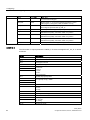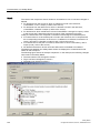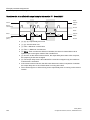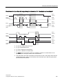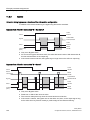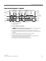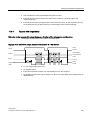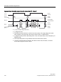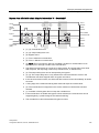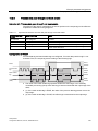
1
Safety Matrix ___________________ Preface 1 ___________________ Product Overview SIMATIC Industrial Software Safety Matrix 2 ___________________ Installing 3 ___________________ Software user interface 4 ___________________ Configuring 5 ___________________ Access protection Configuration Manual 6 ___________________ Transferring a Safety Matrix 7 ___________________ Compiling and downloading Operator control and 8 ___________________ monitoring Documentation of a Safety 9 ___________________ Matrix Acceptance test for a Safety 10 ___________________ Matrix Example parameter 11 ___________________ assignments 02/2010 A5E00265325-03 Legal information Legal information Warning notice system This manual contains notices you have to observe in order to ensure your personal safety, as well as to prevent damage to property. The notices referring to your personal safety are highlighted in the manual by a safety alert symbol, notices referring only to property damage have no safety alert symbol. These notices shown below are graded according to the degree of danger. DANGER indicates that death or severe personal injury will result if proper precautions are not taken. WARNING indicates that death or severe personal injury may result if proper precautions are not taken. CAUTION with a safety alert symbol, indicates that minor personal injury can result if proper precautions are not taken. CAUTION without a safety alert symbol, indicates that property damage can result if proper precautions are not taken. NOTICE indicates that an unintended result or situation can occur if the corresponding information is not taken into account. If more than one degree of danger is present, the warning notice representing the highest degree of danger will be used. A notice warning of injury to persons with a safety alert symbol may also include a warning relating to property damage. Qualified Personnel The product/system described in this documentation may be operated only by personnel qualified for the specific task in accordance with the relevant documentation for the specific task, in particular its warning notices and safety instructions. Qualified personnel are those who, based on their training and experience, are capable of identifying risks and avoiding potential hazards when working with these products/systems. Proper use of Siemens products Note the following: WARNING Siemens products may only be used for the applications described in the catalog and in the relevant technical documentation. If products and components from other manufacturers are used, these must be recommended or approved by Siemens. Proper transport, storage, installation, assembly, commissioning, operation and maintenance are required to ensure that the products operate safely and without any problems. The permissible ambient conditions must be adhered to. The information in the relevant documentation must be observed. Trademarks All names identified by ® are registered trademarks of the Siemens AG. The remaining trademarks in this publication may be trademarks whose use by third parties for their own purposes could violate the rights of the owner. Disclaimer of Liability We have reviewed the contents of this publication to ensure consistency with the hardware and software described. Since variance cannot be precluded entirely, we cannot guarantee full consistency. However, the information in this publication is reviewed regularly and any necessary corrections are included in subsequent editions. Siemens AG Industry Sector Postfach 48 48 90026 NÜRNBERG GERMANY A5E00265325-03 Ⓟ 02/2010 Copyright © Siemens AG 2010. Technical data subject to change Preface Preface Purpose of this documentation The information in this manual enables you to configure "S7 F/FH Systems" fail-safe systems using Safety Matrix V6.2. In addition, you need the following manuals: ● "Safety Engineering in SIMATIC S7 (http://support.automation.siemens.com/WW/view/en/12490443)" System Manual ● "S7 F/FH Systems Configuring and Programming (http://support.automation.siemens.com/WW/view/en/2201072)" Programming and Operating manual Basic knowledge requirements General basic knowledge of automation engineering is needed to understand this documentation. Basic knowledge of the following is also necessary: ● Fail-safe automation systems ● S7-400H automation systems ● S7 F/FH Systems ● Distributed I/O systems on PROFIBUS DP ● STEP 7/PCS 7 basic software, particularly: – Working with SIMATIC Manager – Hardware configuration with HW Config – Communication between CPUs – CFC optional software – PCS 7 (for Safety Matrix Viewer) Safety Matrix Configuration Manual, 02/2010, A5E00265325-03 3 Preface Scope of this documentation Optional package Safety Matrix Editor optional package Order number Release number and higher License 6ES7833-1SM42-0YA5 V6.2 Single, Trial (1 month) Full version: V6.2 Floating, Trial (14 days) including authorization license Safety Matrix Engineering Tool optional package including authorization license 6ES7833-1SM02-0YA5 Upgrade version from V5.2 or V6.1: Floating (as upgrade), Trial (14 days) 6ES7833-1SM02-0YE5 Safety Matrix Viewer optional package Full version: V6.2 Floating, Trial (14 days) 6ES7833-1SM62-0YA5 including authorization license Upgrade version from V5.2 or V6.1: Floating (as upgrade), Trial (14 days) 6ES7833-1SM62-0YE5 The optional packages of the Safety Matrix are used for the safety life cycle engineering and management of S7 F/FH Systems fail-safe automation systems and provide support for all phases of the safety life cycle. 4 Safety Matrix Configuration Manual, 02/2010, A5E00265325-03 Preface What's New? ● Description of the following important innovations: – Revision/expansion of the user interface – Revision of tag entry – Preprocessing for Cause Tags – Expanded options for causes (pre-alarm for analog values, mutually exclusive tag simulation, Effect Tag as internal reference) – Expanded setting options for channel drivers – Inclusion of customer-specific F-channel drivers – Expanded options for effects (mutually exclusive tag simulation, pre-alarm for override timeout) – Doubling of available Safety Matrix intersections to 1024 – Enhanced operator control and monitoring features (maintenance changes, status colors) – Adjustable colors – Colored representation of individual tags in online mode – Revision/extension of alarm behavior by means of three new function blocks for alarms (F_SC_AL, F_SE_AL, F_MA_AL) and three new Safety Matrix block icons for operator control – Selective representation of Safety Matrix in Safety Matrix Viewer: individual cause with associated effects; individual effect with associated causes – Handling of multiple Safety Matrices with different versions in the same PCS 7 OS Approvals The Safety Matrix optional packages are certified for use in safety mode up to: ● Safety Integrity Level SIL3 according to IEC 61508 ● Category 4 according to EN 954-1 ● Performance Level (PL) e according to ISO 13849-1:2006 or EN ISO 13849-1:2008 Safety Matrix Configuration Manual, 02/2010, A5E00265325-03 5 Preface Position in the information landscape You will need supplementary documentation for working with the Safety Matrix according to the application. This documentation includes references to the supplementary documentation where appropriate. For more information, refer to the FAQs at: (http://support.automation.siemens.com/WW/view/en/26091998/133000) Documentation for S7 F/FH Systems Brief Description of Relevant Contents The "S7 F/FH Systems, Configuring and Programming (http://support.automation.siemens.com/WW/view/en/2201072)" Programming and Operating Manual describes the configuring and programming of S7 F/FH Systems fail-safe systems with the aid of S7 F Systems. The "Automation System S7-400 Hardware and Installation (http://support.automation.siemens.com/WW/view/en/1117849)" Installation Manual describes the assembly and wiring of S7-400 systems. The "Automation System S7-400H Fault-Tolerant Systems (http://support.automation.siemens.com/WW/view/en/1186523)" Manual describes the CPU 41x-H central processing units and the tasks required to set up and commission an S7-400H fault-tolerant system. Safety Engineering in SIMATIC S7 The "Safety Engineering in SIMATIC S7 (http://support.automation.siemens.com/WW/view/en/12490443)" System Manual provides an informational overview of the use, installation, and mode of operation of the S7 Distributed Safety and S7 F/FH Systems fail-safe automation systems and describes basic properties and detailed technical information about these fail-safe systems. STEP 7 manuals 6 The "Configuring Hardware and Communication Connections with STEP 7 V5.4 (http://support.automation.siemens.com/WW/view/en/18652631)" Manual describes the operation of the relevant standard tools of STEP 7. The "System Software for S7-300/400 System and Standard Functions (http://support.automation.siemens.com/WW/view/en/1214574)" Reference Manual describes functions for access and diagnostics of distributed I/O and CPUs. The "CFC for S7 Continuous Function Chart (http://support.automation.siemens.com/WW/view/en/21401430)" Manual/online help provides a description of programming with CFC. "Modifying the System during Operation via CiR (http://support.automation.siemens.com/WW/view/en/14044916)" Manual Safety Matrix Configuration Manual, 02/2010, A5E00265325-03 Preface Documentation for Brief Description of Relevant Contents Describes how to operate the standard tools of STEP 7. Contains information on configuring and assigning parameters for I/Os with HW Config. STEP 7 Online Help PCS 7 The PCS 7 manuals describe operation of the PCS 7 process control system (necessary when the S7 F-System is integrated into a higher-level process control system): "Engineering System (http://support.automation.siemens.com/WW/view/en/27002802)" Configuring Manual "Fault-Tolerant Process Control Systems (http://support.automation.siemens.com/WW/view/en/27002533)" Configuring Manual "Operating Station (http://support.automation.siemens.com/WW/view/en/27002758)" Configuring Manual "PC Configuration and Authorization (http://support.automation.siemens.com/WW/view/en/27002558)" Operating Manual Guide This documentation describes the use of the Safety Matrix Engineering Tool, Safety Matrix Viewer, and Safety Matrix Editor optional packages. It includes both instructional material and reference material (description of possible parameter assignments). The following topics are addressed: ● Configuring the safety program (safety-related user program) for S7 F/FH Systems ● Transferring, compiling, and downloading the Safety Matrix ● Access protection for the Safety Matrix ● Operator control and monitoring in PCS 7 ● Support for the system acceptance test Conventions In this documentation, the terms "safety engineering" and "fail-safe engineering" are used synonymously. The same applies to the terms "fail-safe" and "F-". The term "configuring" used here corresponds to the term "programming" used in the referenced documentation. When "S7 F Systems" appears in italics, it refers to the optional package for the "S7 F/FH Systems" fail-safe system. The term "safety program" refers to the fail-safe portion of the user program and is used instead of "fail-safe user program", "F-program", etc. For purposes of contrast, the nonsafety-related user program is referred to as the "standard user program". "F-CPU" denotes a CPU with fail-safe capability. An F-CPU with fail-safe capability is a central processing unit that is approved for use in S7 F/FH Systems. Safety Matrix Configuration Manual, 02/2010, A5E00265325-03 7 Preface Additional support If you have further questions about the use of products presented in this manual, contact your local Siemens representative. Your contact persons are listed in the Internet (http://www.siemens.com/automation/partner). A guide to the technical documentation for the various SIMATIC products and systems is available in the Internet (http://www.siemens.com/simatic-tech-doku-portal). You will find the online catalog and online ordering system in the Internet (http://mall.automation.siemens.com). Training center We offer courses to help you get started with the SIMATIC S7 automation system. Contact your regional training center or the central training center in D 90327 Nuremberg, Federal Republic of Germany. You will find more information in the Internet (http://www.sitrain.com). H/F Competence Center The H/F Competence Center in Nuremberg offers special workshops on SIMATIC S7 failsafe and fault-tolerant automation systems. The H/F Competence Center can also provide assistance with onsite configuration, commissioning and troubleshooting. For questions about workshops, etc., contact: [email protected] Technical Support To contact Technical Support for all Industry Automation products, use the Support Request Web form (http://www.siemens.com/automation/support-request). Additional information on our Technical Support is available in the Internet (http://www.siemens.com/automation/service). Service & Support on the Internet In addition to our documentation, our complete knowledge base is available online in the Internet (http://www.siemens.com/automation/service&support). There, you will find the following information: ● Newsletters providing the latest information on your products. ● A search engine in Service & Support for locating the documents you need. ● A forum where users and experts from all over the world exchange ideas. ● Your local contact person for Industry Automation products is listed in the Contacts database. ● Information about on-site service, repairs, spare parts, and much more is available under "Repairs, spare parts, and consulting". 8 Safety Matrix Configuration Manual, 02/2010, A5E00265325-03 Preface Important note for maintaining the operational safety of your system Note Systems with safety-related characteristics are subject to special operational safety requirements on the part of the operator. The supplier is also obliged to comply with special product monitoring measures. For this reason, we publish a special newsletter containing information on product developments and features that are (or could be) relevant to operation of safety-related systems. By subscribing to the relevant newsletter, you will always have the latest information and able to make changes to your system, when necessary. To subscribe, go to the Internet (https://www.automation.siemens.com/WW/newsletter/guiThemes2Select.aspx?HTTPS=RE DIR&subjectID=2). There, you can register for the following newsletters: S7-300/S7-300F S7-400/S7-400H/S7-400F/FH Distributed I/O SIMATIC Industrial Software To receive these newsletters, select the check box "Update". Warnings index Warning Warning notices of the "S7 F/FH Systems" Programming and Operating Manual Safe state for digital F-I/O Operation of Safety Matrix Check installed version of the Safety Matrix components Assign a unique name for each Safety Matrix Editing of the Safety Matrix file Assigning colors Effect on downloading of changes Transfer with "Chart + Parameters" option Nested chart of the channel drivers Nested chart of the matrix logic Safety Matrix basic chart Warning and safety notices in the user manual for Safety Matrix V5.2 Independent paths to the display Standard operator The "Secure Write" functionality allows changes to the safety program to be made during RUN mode Operating a Safety Matrix Secure Write: checking correct functioning of the operation Checking a transaction Checking the technological assignment Cancelation of a transaction Reintegration of the F-channel drivers Safety Matrix Configuration Manual, 02/2010, A5E00265325-03 Section 1.1 1.4 2.1 2.2 3.1 3.2 4.2.2 6.1 6.1 6.1 6.1 6.1 8.1 8.1 8.5 8.5.2.1 8.5.2.1 8.5.2.1 8.5.2.1 8.5.2.1 8.5.2.1 8.5.3.1 9 Preface 10 Safety Matrix Configuration Manual, 02/2010, A5E00265325-03 Table of contents Preface ...................................................................................................................................................... 3 1 2 3 4 Product Overview .................................................................................................................................... 15 1.1 What is the Safety Matrix? ...........................................................................................................15 1.2 Optional packages of the Safety Matrix .......................................................................................18 1.3 Example view of a Safety Matrix..................................................................................................19 1.4 Definition of terms ........................................................................................................................20 1.5 Overview of procedure.................................................................................................................23 Installing .................................................................................................................................................. 25 2.1 Requirements for installation .......................................................................................................25 2.2 Installing .......................................................................................................................................26 2.3 Uninstalling Safety Matrix V6.2 Components ..............................................................................28 2.4 Introducing the new Safety Matrix block icon into the PCS 7 OS................................................28 2.5 2.5.1 2.5.2 2.5.3 2.5.4 2.5.5 Upgrading to Safety Matrix V6.2 ..................................................................................................30 Overview of upgrading .................................................................................................................30 Use case 1 ...................................................................................................................................32 Use case 2 ...................................................................................................................................37 Use case 3 ...................................................................................................................................41 Use case 4 ...................................................................................................................................43 Software user interface............................................................................................................................ 45 3.1 Inserting a new Safety Matrix.......................................................................................................45 3.2 Menu bar of the Safety Matrix......................................................................................................47 Configuring .............................................................................................................................................. 51 4.1 4.1.1 4.1.2 4.1.3 4.1.4 4.1.5 4.1.6 4.1.6.1 4.1.6.2 4.1.6.3 4.1.6.4 4.1.7 Overview of Configuring...............................................................................................................51 Basic procedure for creating the safety program.........................................................................51 Tags of the Safety Matrix .............................................................................................................53 Syntax rules for tag names in the Safety Matrix ..........................................................................55 Preprocessing ..............................................................................................................................57 F-channel drivers .........................................................................................................................58 Message configuration.................................................................................................................60 Overview for configuring messages.............................................................................................60 Safety Matrix message block F_MA_AL ......................................................................................62 Cause message block F_SC_AL .................................................................................................63 Effect message block F_SE_AL...................................................................................................68 OS interface .................................................................................................................................73 4.2 4.2.1 4.2.2 4.2.3 Editing the properties of the Safety Matrix...................................................................................74 "Properties" dialog box of the Safety Matrix ................................................................................74 "Adjust" dialog boxes ...................................................................................................................79 "Change tracking" menu command .............................................................................................81 4.3 Configuring the causes ................................................................................................................82 Safety Matrix Configuration Manual, 02/2010, A5E00265325-03 11 Table of contents 4.3.1 4.3.2 4.3.3 4.3.4 4.3.5 4.3.6 4.3.7 Overview for configuring the causes........................................................................................... 82 Creating/changing a cause and the rows for a cause................................................................. 84 Overview of the "Cause details - Cause x" dialog box................................................................ 85 "Cause details" dialog box - "Configure" tab............................................................................... 86 "Cause details" dialog box - "Analog parameters" tab ................................................................ 88 "Cause details" dialog box - "Options" tab .................................................................................. 89 "Cause details" dialog box - "Alarms" tab ................................................................................... 91 4.4 4.4.1 4.4.2 4.4.3 4.4.4 4.4.5 4.4.6 Configuring the effects ................................................................................................................ 92 Overview for configuring the effects............................................................................................ 92 Creating/changing an effect and the column for an effect .......................................................... 92 Overview of the "Effect details - Effect x" dialog box .................................................................. 93 "Effect details" dialog box - "Configure" tab ................................................................................ 94 "Effect details" dialog box - "Options" tab ................................................................................... 96 "Effect details" dialog box - "Alarms" tab .................................................................................... 99 4.5 4.5.1 4.5.2 Configuring the intersections..................................................................................................... 100 Editing or changing intersections .............................................................................................. 100 "Intersection details" dialog box - "Configure" tab..................................................................... 101 4.6 4.6.1 4.6.2 Importing/exporting a cause/effect matrix file ........................................................................... 103 Importing a cause/effect matrix file (.cem) to a PCS 7 project.................................................. 103 Exporting a cause/effect matrix file (.cem)................................................................................ 104 4.7 Safety Matrix Editor................................................................................................................... 105 5 Access protection .................................................................................................................................. 107 6 Transferring a Safety Matrix................................................................................................................... 109 7 8 12 6.1 Transferring the Safety Matrix to the project............................................................................. 109 6.2 F-runtime group and run sequence........................................................................................... 116 6.3 Notes for working with CFC ...................................................................................................... 117 Compiling and downloading................................................................................................................... 119 7.1 Compiling and downloading to the F-CPU................................................................................ 119 7.2 Compiling and downloading to the Operator Station ................................................................ 120 Operator control and monitoring ............................................................................................................ 123 8.1 Overview of operator control and monitoring ............................................................................ 123 8.2 Starting online mode in the Engineering Tool ........................................................................... 125 8.3 Opening the Safety Matrix Viewer faceplates ........................................................................... 125 8.4 8.4.1 8.4.2 Monitoring.................................................................................................................................. 128 Color codes for status display ................................................................................................... 128 Status displays .......................................................................................................................... 129 8.5 8.5.1 8.5.2 8.5.2.1 8.5.2.2 8.5.3 8.5.3.1 8.5.3.2 8.5.3.3 Operating................................................................................................................................... 131 Initiator and confirmer permissions ........................................................................................... 132 Secure Write ............................................................................................................................. 133 Transaction for Secure Write .................................................................................................... 133 Variants of Secure Write ........................................................................................................... 136 Operation of a Safety Matrix ..................................................................................................... 136 Operator inputs using the control bar in online mode and in the Safety Matrix Viewer ............ 136 Example: Reset effect ............................................................................................................... 140 Maintenance changes ............................................................................................................... 141 Safety Matrix Configuration Manual, 02/2010, A5E00265325-03 Table of contents 8.6 8.6.1 8.6.2 8.6.3 8.6.4 9 Events and messages................................................................................................................144 Messages in the event log of the Safety Matrix .........................................................................144 Operation messages of the Safety Matrix Viewer......................................................................145 PCS 7 alarm signals in the WinCC alarm logging .....................................................................146 Alarms ........................................................................................................................................146 Documentation of a Safety Matrix.......................................................................................................... 147 9.1 Comparing Safety Matrices........................................................................................................147 9.2 Comparing CFC charts ..............................................................................................................148 9.3 Configuration report ...................................................................................................................151 9.4 Validation report.........................................................................................................................152 10 Acceptance test for a Safety Matrix ....................................................................................................... 153 11 Example parameter assignments .......................................................................................................... 157 11.1 11.1.1 11.1.2 11.1.3 11.1.4 11.1.5 11.1.6 Example parameter assignments for causes.............................................................................157 Time behavior ............................................................................................................................157 Inhibit..........................................................................................................................................159 Bypass .......................................................................................................................................159 Auto acknowledge active cause.................................................................................................160 Trip on bad quality .....................................................................................................................160 Alarm on any input trip ...............................................................................................................160 11.2 11.2.1 11.2.2 11.2.3 11.2.4 11.2.5 Example parameter assignments for effects .............................................................................161 Reset/override............................................................................................................................161 Reset/override with output delay................................................................................................163 Bypass .......................................................................................................................................166 Bypass with output delay ...........................................................................................................169 Process data pass through and mask enable............................................................................173 Glossary ................................................................................................................................................ 175 Index...................................................................................................................................................... 183 Safety Matrix Configuration Manual, 02/2010, A5E00265325-03 13 Table of contents 14 Safety Matrix Configuration Manual, 02/2010, A5E00265325-03 Product Overview 1.1 1 What is the Safety Matrix? Comprehensive tool for safety life cycle The SIMATIC Safety Matrix is the comprehensive tool for safety life cycle engineering and management of S7 F/FH Systems fail-safe automation systems and provides support for all phases of the safety life cycle: ● The Safety Matrix is a configuring tool for processes that require safety-related reactions to defined conditions. ● With the Safety Matrix, a CFC safety program can be created for S7 F/FH Systems according to the rules of a cause/effect matrix. ● The Safety Matrix is an integrated tool for all activities, maintenance, error handling, and change management during operation. Safety Matrix Configuration Manual, 02/2010, A5E00265325-03 15 Product Overview 1.1 What is the Safety Matrix? Use in process control The figure below shows you the possible ways of integrating S7 F/FH Systems with the Safety Matrix into you process automation system with PCS 7. 6KDUHG0DWUL[ )LOHFHP 2SHUDWRU6WDWLRQ26 3& &HQWUDO(QJLQHHULQJ(6 6DIHW\0DWUL[ (QJLQHHULQJ7RRO 6DIHW\0DWUL[ (GLWRU 3& 3& 6DIHW\0DWUL[ 9LHZHU 3& 6WDQGDUG(WKHUQHW 6HUYHU ,QGXVWULDO(WKHUQHWRU352),%86 6+ 6) 6\VWHP 66WDQGDUG 6)+ 6\VWHP )0RGXOHV )60V 6WDQGDUG0RGXOHV )60V (76 (76 )60V 6WDQGDUG60V )60V 6WDQGDUG60V 6WDQGDUG60V (70 (70 (70 )DLO6DIH'36WDQGDUG6ODYH HJODVHUVFDQQHUOLJKWDUUD\ )0RGXOHV (7SUR )DLO6DIH3$)LHOG'HYLFH ),20RGXOH '33$&RXSOHU (7HFR %XUQHU &RDO3XOYHUL]HU 16 (PHUJHQF\6723 %RLOHU3URWHFWLRQ ,QVWDQGDUGPRGH Safety Matrix Configuration Manual, 02/2010, A5E00265325-03 Product Overview 1.1 What is the Safety Matrix? Relationship to S7 F Systems WARNING Warning notices of the "S7 F/FH Systems" Programming and Operating Manual The Safety Matrix is an optional package for S7 F/FH Systems. You must read, understand, and comply with all warning notices in the "S7 F/FH Systems Configuring and Programming" Programming and Operating Manual. The following table illustrates the relationship between the Safety Matrix and S7 F Systems. S7 F Systems Safety Matrix Programming with CFC Intuitive configuring based on the conventional cause/effect method CFC as basis (charts, run-time groups, run sequence) S7 F Systems safety concept CFC documentation Documentation through printouts of the Safety Matrix Basic mode of operation Analysis phase When performing a risk assessment for the system, the user can assign events occurring during a process (causes) to precisely defined reactions (effects) and thus specify the system behavior. The user enters possible process events (one or more entries) in the Safety Matrix and then configures the events in terms of type, number, logic combinations, possible delays and interlocks, and any permitted deviations. Next, the user defines the reactions (one or more outputs) to a particular event. The causes and effects are linked by simply clicking the cell at their intersection. When the Safety Matrix is saved, the configuration is checked for validity. The Safety Matrix documents the safety-instrumented function groups, and the cause/effect matrix itself is an important component of the safety program specification. Implementation phase The safety program is specified by configuring the cause/effect parameters in the Safety Matrix. Using these specifications, the Safety Matrix automatically generates the F-system program logic based on CFC using F-blocks from the Safety Matrix library. In addition, the Safety Matrix provides revision and change tracking as well as functions for comparing matrices and for support during acceptance testing of the system. Safety Matrix Configuration Manual, 02/2010, A5E00265325-03 17 Product Overview 1.2 Optional packages of the Safety Matrix Operational phase The Engineering Tool of the Safety Matrix and the viewer available on the SIMATIC PCS 7 Operator Station enable operator control and monitoring of the system in safety mode as well. The signal status is represented online in the cause/effect matrix. The operator can display and save initial alarm messages and specify that safety-relevant events be recorded. Parameter changes, for example, using bypass, reset, and override functions, are also supported. Safety life cycle management functions for revision management as well as for the documentation of operator inputs and program changes supplement the configuring, operational, and service functions of the Safety Matrix. Achievable Safety Requirements The following safety requirements are met with the Safety Matrix: ● Up to Safety Integrity Level SIL3 according to IEC 61508 ● Up to Category 4 according to EN 954-1 ● Up to Performance Level (PL) e according to ISO 13849-1:2006 or EN ISO 13849-1:2008 1.2 Optional packages of the Safety Matrix Optional packages and range of functions The Safety Matrix consists of three products that can also be ordered as three separate optional packages. Table 1- 1 Range of functions of the Safety Matrix optional packages Optional package Range of functions Environment Operating mode Utilization phase Safety Matrix Editor Creating and configuring a Safety Matrix on a PC outside of PCS 7 or STEP 7, including checking the configuration for validity, documentation, and creation of an importable .cem matrix file Stand-alone Offline Analysis phase (planning and configuration) Safety Matrix Engineering Tool Creating (importing a .cem matrix file), configuring a Safety Matrix, automatic generation and downloading of CFC charts including driver blocks to a PCS 7 project, operator control and monitoring using STEP 7 SIMATIC Manager on a PCS 7 Engineering System (ES) Engineering System (ES) PCS 7 or STEP 7 and Offline, online Analysis, implementation, and operational phase (total safety life cycle) PCS 7 Online Operational phase (operator control and monitoring) Safety Matrix Viewer 18 Operator control and monitoring by means of a faceplate on a PCS 7 Operator Station (OS) CFC Operator Station (OS) Safety Matrix Configuration Manual, 02/2010, A5E00265325-03 Product Overview 1.3 Example view of a Safety Matrix 1.3 Example view of a Safety Matrix Example view of a Safety Matrix The following figure shows an example view of a Safety Matrix. (IIHFW ,QWHUVHFWLRQ &DXVH Example: If Cause 1 becomes active (trip if FALSE, i.e. when input tag = "0"), Effect 1 is tripped and stored. Safety Matrix Configuration Manual, 02/2010, A5E00265325-03 19 Product Overview 1.4 Definition of terms 1.4 Definition of terms Main terms of the Safety Matrix are explained below. Cause A cause represents a process event. The cause represents the trigger for activating an effect. Certain conditions must be fulfilled in order for the cause to become active and thus to trigger an effect defined by an intersection. Analog or discrete values can be selected as the input type. The values of at least one but no more than three input tags together with the function type represent a cause. You can create a maximum of 128 causes. Causes are arranged in rows in the Safety Matrix. Effect An effect represents the reaction that the Safety Matrix exerts on the process. Certain conditions must be fulfilled in order for the effect to become active and thus to trigger an action in the process by means of its output tags. The values of at least one but no more than four discrete output tags define the action to be performed on the process. The activation of an effect depends on various factors (status of the assigned causes, type of intersection, specified options for the effect). You can create a maximum of 128 effects. Effects are arranged in columns in the Safety Matrix. Intersection The Safety Matrix intersections specify which causes trigger the respective effects. You can define up to 1024 intersections. Active A cause or effect can be active, which means that it has been tripped. Whether or not a cause is active and when it becomes active is determined by the input tags, the function type, and the options for the cause. The activation of an effect depends on the relationship (defined by intersections) to the causes and the options for the effect. If an effect is active, the output tags are set to "0" or "1", depending on the "Energize-to-trip" option. 20 Safety Matrix Configuration Manual, 02/2010, A5E00265325-03 Product Overview 1.4 Definition of terms Inactive A cause or effect can be inactive, which means that the conditions for activation are not fulfilled. Whether or not the cause is inactive is determined by the input tags, the function type, and the options for the cause. The deactivation of an effect depends on the relationship (defined by intersections) to the causes and the options for the effect. If an effect is inactive, the output tags are set to "0" or "1", depending on the "Energize-to-trip" option. Energize-to-trip (ETT) Trip if TRUE: The cause is active if input tag = "1" (high-active). The output tag is "1" if the effect is active. WARNING Safe state for digital F-I/O The safety concept is based on the existence of a safe state at all process variables. For digital F-I/O, this is the value "0"; this applies to sensors as well to actuators. For this reason, you must implement suitable measures, such as redundancies, in the application. Deenergize-to-trip (DTT) Trip if FALSE: The cause is active if input tag = "0" (low-active). The output tag is "0" if the effect is active. This negative logic is the default setting for the inputs and outputs of the Safety Matrix. By default, the input tag activates the cause according to the "Deenergize-to-trip" principle, which means that a cause becomes active if the input tag is "0". The cause becomes inactive if input tag = "1". If a cause has more than one input tag, the function type for activating the cause must also be taken into consideration. The behavior is the same with regard to the output tags. If the effect is active, the output tags are set to "0". If inactive, they are set to "1". Function type The function type combines with the input tags and their options to govern whether and when a cause is active or inactive. ● Normal: one input tag ● 2oo3: three input tags, 2 out of 3 tripping criteria must be fulfilled ● AND: 2-3 input tags, all tripping criteria must be fulfilled ● OR: 2-3 input tags, at least one tripping criterion must be fulfilled ● For note only Safety Matrix Configuration Manual, 02/2010, A5E00265325-03 21 Product Overview 1.4 Definition of terms Bypass Bypass function that is normally used for maintenance purposes (e.g., for checking effect logic, replacing a sensor). A Boolean tag can be selected or entered as the "bypass tag". The bypass becomes active if the value of the bypass tag is TRUE. In addition to the "bypass TAG", the "soft bypass" function can also be allowed. Then, the operator can set the bypass manually by means of an operator input via Secure Write. When a bypass is active, a cause or effect cannot become active even though it should be active based on its tripping condition and options. Safety instrumented function groups (SIF) You can create your own safety instrumented function groups for your application, i.e., by dividing your application into function groups that you can then monitor and change selectively in the Safety Matrix Engineering Tool and Safety Matrix Viewer (e.g., "level measurement and shut off"). In order to use this function, you must assign the individual causes and effects of the safety program to your safety instrumented functions groups. Then, you can display one or more (or all) safety-instrumented function groups. Secure Write The "Secure Write" functionality allows operator inputs to be made to the Safety Matrix. This can take place in online mode of the Safety Matrix Engineering Tool or from the PCS 7 OS via the Safety Matrix Viewer. Transaction for Secure Write You carry out a Secure Write transaction for the purpose of making operator inputs to the Safety Matrix in online mode of the Safety Matrix Engineering Tool or from the PCS 7 OS via the Safety Matrix Viewer. The transaction consists of a sequence of operations that can be performed by one or two operators. The transaction must be completed within a time interval specified by the user (timeout). If the transaction is not finished before the timeout expires, the transaction is automatically canceled. 22 Safety Matrix Configuration Manual, 02/2010, A5E00265325-03 Product Overview 1.5 Overview of procedure 1.5 Overview of procedure This chapter provides a brief overview of the procedure to be followed when using Safety Matrix components within the PCS 7 automation system. Overview of procedure Table 1- 2 Overview of procedure Step Required user steps Safety Matrix component See Chapter 1 Inserting a new Safety Matrix Engineering Tool 3.1 2 Editing the properties of the Safety Matrix Engineering Tool, Editor 4.2 3 Configuring the functions of the Safety Matrix: Engineering Tool, Editor 4 Causes Effects Intersections 4.3 4.4 4.5 4 Transferring a Safety Matrix Engineering Tool 6 5 Transferring and loading Engineering Tool 7 6 Operator control and monitoring Engineering Tool, Viewer 8 7 Documentation of a Safety Matrix Engineering Tool, Editor 9 8 Acceptance test for a Safety Matrix Engineering Tool 10 Safety Matrix Configuration Manual, 02/2010, A5E00265325-03 23 Product Overview 1.5 Overview of procedure 24 Safety Matrix Configuration Manual, 02/2010, A5E00265325-03 2 Installing 2.1 Requirements for installation Hardware components For information on the hardware components of S7 F/FH Systems, refer to the "S7 F/FH Systems Configuring and Programming (http://support.automation.siemens.com/WW/view/en/2201072)" Programming and Operating Manual. Software requirements The following software is required to operate the complete range of functions of the Safety Matrix components. WARNING Operation of Safety Matrix You may only operate the Safety Matrix components in the released system environments. Operation on terminal server/clients or on a virtual server/system is expressly excluded. Safety Matrix Engineering Tool To operate the Safety Matrix Engineering Tool V6.2, you must have installed the following software packages on the ES: ● Supported operating systems – Windows XP SP2 or SP3 – Windows 2003 Server SP1 or SP2, each including R2 ● Required optional packages – S7 F Systems V5.2 SP1 or higher – Failsafe Blocks (V1_2) or S7 F Systems Lib V1_3 F-library – For offline testing: S7-PLCSIM, dependent on the installed S7 F Systems version – Automation License Manager (ALM) V3.0 SP1 or higher ● For use with PCS 7: – PCS 7 V6.1 SP3, PCS 7 V7.0 SP3 or higher, or PCS 7 V7.1 HF1 or higher – Windows version corresponding to PCS 7 version ● For use without PCS 7: – STEP 7 V5.4 SP3 or higher – CFC V7.0 SP1 or higher Safety Matrix Configuration Manual, 02/2010, A5E00265325-03 25 Installing 2.2 Installing Safety Matrix Viewer To operate the Safety Matrix Viewer V6.2, you must have installed the following software packages on the OS: ● Supported operating systems – Windows XP SP2 or SP3 – Windows 2003 Server SP1 or SP2 RC2 ● PCS 7 V6.1 SP3, PCS 7 V7.0 SP3 or higher, or PCS 7 V7.1 HF1 or higher ● Automation License Manager (ALM) V3.0 SP1 or higher With Safety Matrix Viewer V6.2, operator control and monitoring of Safety Matrices of versions V5.2, V6.1, and V6.2 is possible. Safety Matrix Editor To operate the Safety Matrix Editor V6.2, you must have installed the following software packages on your PC: ● Windows XP SP2 or higher, or Windows Server 2003 SP 1 or higher 2.2 Installing Note Installations of older versions of the Safety Matrix components must be uninstalled prior to installing Safety Matrix V6.2. Note For installation of the Safety Matrix Engineering Tool/Viewer V6.2, the same requirements apply as described in the PCS 7 Operating Manual "PC Configuration and Authorization (http://support.automation.siemens.com/WW/view/en/27002558)". WARNING Check installed version of the Safety Matrix components After installation of the Safety Matrix components, verify the respective version via "Installed SIMATIC software" (VersionView). 26 Safety Matrix Configuration Manual, 02/2010, A5E00265325-03 Installing 2.2 Installing Reading Readme files Important current information regarding the delivered software is available in the Readme files "Safety Matrix Engineering Tool V6.2 – Readme", "Safety Matrix Viewer V6.2 – Readme", "Safety Matrix Editor V6.2 – Readme", and "Safety Matrix AS-OS-Engineering – Readme". You can arrange for the Readme files to be displayed at the end of the corresponding setup program. You can also open the Readme files later by selecting Start > SIMATIC > Product Information > English. You will find the Readme files in the installation directory of the respective Safety Matrix component. Installing Safety Matrix Engineering Tool V6.2 1. Start your ES. Ensure that no STEP 7 applications are open. 2. Insert the product CD for the Safety Matrix Engineering Tool V6.2. 3. Start the SETUP.EXE program on the CD. 4. Follow the setup program instructions. 5. If you are using Safety Matrices in a PCS 7 environment, select the "AS-OS Engineering" check box. Installing Safety Matrix Viewer V6.2 1. Start your ES/OS. Ensure that no SIMATIC applications are open. 2. Insert the product CD of the Safety Matrix Viewer V6.2. 3. Start the SETUP.EXE program on the CD. 4. Follow the setup program instructions. Installing Safety Matrix Editor V6.2 1. Start your PC. 2. Insert the product CD of the Safety Matrix Editor V6.2. 3. Start the SETUP.EXE program on the CD. 4. Follow the setup program instructions. License key (usage authorization) A license key is required for each component of Safety Matrix V6.2. This license key is installed in the same way as for STEP 7 and the optional packages. For information on installing and working with license keys, refer to the Readme file and the STEP 7 basic help. Documentation When a component of Safety Matrix V6.2 is installed, a shortcut for German and English with the name “Safety Matrix - Engineering Tool” is stored in the respective SIMATIC directory for manuals (Start > SIMATIC > Documentation). Safety Matrix Configuration Manual, 02/2010, A5E00265325-03 27 Installing 2.3 Uninstalling Safety Matrix V6.2 Components 2.3 Uninstalling Safety Matrix V6.2 Components Uninstalling Safety Matrix V6.2 components Note For uninstalling the Safety Matrix Engineering Tool/Viewer V6.2, the same requirements apply as described in the "PCS 7 V7.0 PC Configuration and Authorization (http://support.automation.siemens.com/WW/view/en/27002558)" Manual. Use the normal procedure in Windows for uninstalling software: 1. In Windows, double-click the "Add or Remove Programs" icon in "Control Panel" to open the dialog box for installing software. 2. Select the "SIMATIC SafetyMatrix Engineering Tool V6.2", "SIMATIC SafetyMatrix AS/OS Engineering V6.2", and/or "SIMATIC SafetyMatrix Viewer V6.2" or "SIMATIC SafetyMatrix Editor V6.2" entry in the list of installed software. Click the "Add/Remove" button to uninstall the software. 2.4 Introducing the new Safety Matrix block icon into the PCS 7 OS Note Safety Matrix Viewer V6.2 contains block icons for Safety Matrix V6.2 and a block icon for Safety Matrix V5.2 or V6.1. This allows you to commonly operate the following Safety Matrix versions on a single OS: V6.2 and V5.2 V6.2 and V6.1 Converting pictures If you are using PCS7 V7.0 or higher, you must convert the pictures to the WinCC version you are using. Follow the steps outlined below. 1. Launch WinCC Explorer for the OS contained in the Safety Matrix project. 2. Right-click the "Graphics Designer" entry in WinCC Explorer. 3. Select "Convert pictures" in the context menu. All pictures are converted. 4. Select the following pictures in the "Basic data" tab to use the OS Project Editor again: – @PG_F_MATCTL* – @PG_F_MA_AL* – @PG_F_SC_AL* – @PG_F_SE_AL* – @PCS7Typicals_S7FSMTX.PDL 28 Safety Matrix Configuration Manual, 02/2010, A5E00265325-03 Installing 2.4 Introducing the new Safety Matrix block icon into the PCS 7 OS Introducing pictures into an existing Safety Matrix project To use the new features of the Safety Matrix faceplate in an existing project, you must update the project. 1. To do so, launch WinCC Explorer for the OS contained in the Safety Matrix project. 2. Open the OS Project Editor and click OK. The project is reconfigured and, as a result, the new block icon will be adopted. 3. Open the Global Script C-Editor and select the Options > Regenerate headers menu command. Without update of the Safety Matrix library If you have chosen to use the Safety Matrix without update of the Safety Matrix library, perform the following step: ● In order to introduce the new block icon into existing plant pictures, you must recompile the relevant project. If necessary, configure the desired permissions for the block icons. With update of the Safety Matrix library If you have chosen to use the Safety Matrix with update of the Safety Matrix library, proceed as follows: ● In order to introduce the new block icon into existing plant pictures, you must recompile the relevant project. Note that the PH assignment and the assignment of permissions is now performed in the Safety Matrix Engineering Tool (see section ""Properties" dialog box of the Safety Matrix (Page 74)"). Recompiling the relevant project 1. To do so, start SIMATIC Manager. 2. Make sure that the "Derive block icons from the plant hierarchy" option is selected in the "Block icons" tab of the object properties for the relevant picture object. (This is the default setting in PCS 7 V7 and higher.) Note If user settings for the block icon of a Safety Matrix are to be retained during a subsequent OS compilation of an existing picture, you must clear the "Derive block icons from the plant hierarchy" option for this WinCC picture. 3. Highlight the OS object and select "Compile" in the context menu to compile the OS. For PCS 7 < V7: Make sure that the "Generate/update block icons" option is selected in the "Compile OS" wizard when selecting the data to be compiled and the scope of the compilation. (This takes place automatically in PCS 7 V7 and higher.) 4. Click the "Compile" button in the last dialog of the "Compile OS" wizard. Safety Matrix Configuration Manual, 02/2010, A5E00265325-03 29 Installing 2.5 Upgrading to Safety Matrix V6.2 Result Once you have performed these steps, your project contains the new Safety Matrix block icon. Repeat these steps for all projects. 2.5 Upgrading to Safety Matrix V6.2 2.5.1 Overview of upgrading Basic procedure for upgrading When Safety Matrix V5.2 or V6.1 is upgraded to V6.2, the following steps must be carried out in the order given: 1. Upgrade the Safety Matrix as described below. 2. If necessary, upgrade the S7 F Systems Lib F-library as described in the "S7 F/FH Systems Configuring and Programming (http://support.automation.siemens.com/WW/view/en/2201072) " Programming and Operating Manual. 3. If necessary, upgrade PCS 7 as described in the PCS 7 documentation. Use cases for upgrading Migration from... Update of Safety Matrix library ...to Safety Matrix V6.2 Safety Matrix V5.2 Required Use case 1 (Page 32) Safety Matrix V6.1 Yes Use case 2 (Page 37) Safety Matrix V6.1 No Use case 3 (Page 41) Safety Matrix V5.2/V6.1, Safety Matrix Viewer upgrade only No Use case 4 (Page 43) 30 Safety Matrix Configuration Manual, 02/2010, A5E00265325-03 Installing 2.5 Upgrading to Safety Matrix V6.2 General notes on upgrading After installation of Safety Matrix V6.2, changes to existing Safety Matrices will cause an upgrade. This upgrade can be performed with or without an upgrade of the Safety Matrix library. See table above. If an upgrade with Safety Matrix library update is performed, the F-CPU must be switched to STOP. Variants when upgrading Before upgrading a specific project to Safety Matrix V6.2, you must choose one of these two variants: Consequences Variant Advantages Disadvantages Without update of the Safety Matrix library Safety program is unchanged, which means a CPU STOP is not necessary. With update of the Safety Matrix library Expanded engineering Expanded functionality for operator control and monitoring Use of different versions on one OS is possible Use of new features is limited Modified safety program, which means a CPU STOP is necessary. If you are upgrading the Safety Matrix to update the Safety Matrix library, you can use the full functionality of the enhanced alarm response. Read about this in the section on "Message configuration (Page 60)" and the section "The "Properties" dialog of the Safety Matrix" (Page 74)", 'Alarms' tab. The message configuration for individual causes/effects is disabled by default. Safety Matrix Configuration Manual, 02/2010, A5E00265325-03 31 Installing 2.5 Upgrading to Safety Matrix V6.2 2.5.2 Use case 1 Objective Update of the Safety Matrix Engineering Tool as well as the Safety Matrix library. Introduction This use case helps you when migrating from Safety Matrix V5.2 to Safety Matrix V6.2. Requirements A project has been compiled and downloaded (acceptance tested, if necessary). This project must contain the Failsafe Blocks (V1_2 + SP1 or higher) of the F-Library. You can verify this as follows: ● Open the block folder of the program in the detail view in SIMATIC Manager. In the "Version (Header)" column, "3.1" (or higher) must be specified for the following F-channel drivers: – F_CH_DI – F_CH_DO – F_CH_AI No changes are allowed to be made offline that have not also been downloaded online. Consequences ● Changing the collective signature ● Requires a complete download with CPU STOP. 32 Safety Matrix Configuration Manual, 02/2010, A5E00265325-03 Installing 2.5 Upgrading to Safety Matrix V6.2 Procedure 1. Create a backup copy of the entire S7 project for comparison purposes before you install Safety Matrix V6.2. 2. Install Safety Matrix V6.2 on the ES. 3. Install Safety Matrix AS OS Engineering on the ES, if necessary. 4. Install Safety Matrix Viewer on the ES/OS, if necessary. 5. Right-click the "Matrices" folder in the S7 program folder and select the Object properties of the matrix folder. 6. On the "Matrix" tab of the object properties, select the Safety Matrix library "SafetyMatrix Lib (V1_3)" you want to use for this S7 program. 7. Confirm the subsequent prompts. The blocks will be copied to the S7 program folder. 8. Open the Safety Matrix and transfer it with the following transfer option settings: – Transfer option "Use imported channel drivers (IEA support)" cleared – Transfer option "Chart + Parameters" selected – Transfer option "Clean nested chart connections" selected – Transfer option "Position blocks" selected along with option "Update all" 9. Perform step 8 for all available Safety Matrices. Meanwhile, other CFC actions are not allowed. 10.Compile the SIMATIC project. 11.Using the Tools > Compare Programs menu command in the Safety Matrix Engineering Tool, compare the safety program with the backup copy from step 1. Following a successful upgrade, the following change is listed for each Safety Matrix: Safety Matrix non-critically changed, New version of matrix, SWC Parameter has been modified 12.Also compare the safety program with the backup copy. To do so, click the Compare... button in the "Customize safety program" dialog box in SIMATIC Manager. Safety Matrix Configuration Manual, 02/2010, A5E00265325-03 33 Installing 2.5 Upgrading to Safety Matrix V6.2 Result of the comparison in Step 12 The result of the comparison is a list with three sections: "Runtime level", "Chart" and "Changed system charts". Changes in the matrix listed in the "Chart" section (format: "Matrix name" chart, "@Matrix name" chart...) better interpreted with the menu command Tools > Compare Programs and can therefore be ignored at this point. The "@FMatrices" chart is created automatically. After a successful upgrade, the following changes are listed in the "Runtime level" section: In each OB with safety program: Block "@F_CycCo-OBxx\F_TEST": Signature Changed In each runtime group with Safety Matrix F-blocks: ● One entry per Safety Matrix: Block "MatrixName\@MatrixName\Libvers(F_AND4)": Added ● One section per Safety Matrix (Status_DB): Block "Matrixname\@Matrixname\C_Status(F_StatDB)": Signature Changed, Interface Changed 'xxx'<->'xxx' SM_VER Value: ’16#0003’ <- ’16#0001’ DB_Num Structure: 'CHAR' <- 'BOOL' FlowCnt Deleted CYC Deleted Block "MatrixName\@MatrixName\E_Status(F_StatDB)": Signature Changed, Interface Changed 'xxx'<->'xxx' SM_VER Value: '16#0003' <- '16#0001' DB_Num Structure: 'CHAR' <- 'BOOL' FlowCnt Deleted CYC Deleted ● One section for each F_Cause F-FB per Safety Matrix Block "Matrixname\@Matrixname\Cxx(F_Cause)": Signature Changed, Interface Changed 'xxx'<->'xxx' SM_VER Value: '16#0003' <- '16#0001' C_Status_DB Structure: 'CHAR' <- 'BOOL' DB_GROUP Added MatrixSize Value: 'Not Interconnected' <'Interconnected (MatrixName\@MatrixName\MatrixName\Size)' For each discrete or analog tag of another Safety Matrix (prefix "@") used: ConnectorName Value: 'MatrixName1\MatrixName1\TAG-Name\Q' <'@MatrixName\TAG-Name' or ConnectorName Value: 'MatrixName1\MatrixName1\TAG-Name\V' <'@MatrixName\TAG-Name' The following default parameters for the operation and monitoring or reporting: P_LIMV_xx Added VMODx_R_yy Added VMODx_B_yy Added HMI Added DB_NUM Added CYC Deleted 34 Safety Matrix Configuration Manual, 02/2010, A5E00265325-03 Installing 2.5 Upgrading to Safety Matrix V6.2 ● One section for the F_Inters F-FB per Safety Matrix Block " MatrixName\@MatrixName\Inters(F_Inters)": Signature Changed, Interface Changed 'xxx'<->'xxx' SM_VER Value: '16#0003' <- '16#0001' C_Status_DB Structure: 'CHAR' <- 'BOOL' MatrixSize Value: 'Not Interconnected' <'Interconnected (MatrixName\@MatrixName\MatrixName\Size)' Inters_xxxx Added E_Trip_DB Structure: 'CHAR' <- 'BOOL' CYC Deleted Using the menu command Tools > Compare Programs and the configuration report, you can create a document about the unused ports. ● One section for each F_Effect F-FB per Safety Matrix Block "MatrixName\@MatrixName\Exx(F_Effect)": Signature Changed, Interface Changed 'xxx'<->'xxx' SM_VER Value: '16#0003' <- '16#0001' E_Trip_DB Structure: 'CHAR' <- 'BOOL' E_Status_DB Structure: 'CHAR' <- 'BOOL' DB_GROUP Added MatrixSize Value: 'Not Interconnected' <'Interconnected (MatrixName\@MatrixName\MatrixName\Size)' The following default parameters for the operation and monitoring or reporting: P_OVTM_xx Added DB_NUM Added CYC Deleted ● One section for the F_Matctl F-FB per Safety Matrix Block "MatrixName\@MatrixName\MatrixName(F_Matctl)": Signature Changed, Interface Changed 'xxx'<->'xxx' SM_VER Value: '16#0003' <- '16#0001' C_Status_DB Structure: 'CHAR' <- 'BOOL' E_Trip_DB Structure: 'CHAR' <- 'BOOL' E_Status_DB Structure: 'CHAR' <- 'BOOL' MatrixID Value: '16#xxxxxxxx' <- '16#xxxxxxxx' TIME_SWC Added EN_SWC Added MatrixSig Value: 'Interconnected (@MatrixName\MatrixSig)' <- 'Not Interconnected' (if necessary) Any_CB Added Any_EB Added Any_CW Added Any_EW Added CAct_Num Added EAct_Num Added DB_NUM Added IntEvent Added Size Value: 'Not Interconnected' <'Interconnected (MatrixName\@MatrixName\Exx\MatrixSize, …)’ ViewTime Added SWC_AKT Added SecCmdStat Added DurationMin Added Safety Matrix Configuration Manual, 02/2010, A5E00265325-03 35 Installing 2.5 Upgrading to Safety Matrix V6.2 Msec Value: 'Interconnected (@MatrixName\Msec)' <- 'Not Interconnected' MaxMsec Value: 'Interconnected (@MatrixName\MaxMsec)' <- 'Not Interconnected' MtxVersion Added DB_NUM_D Added TempBuf1 Value: '''' <- ''1234567890'' TempBuf Value: '''' <- ''1234567890'' EV_ID Deleted ALARM_EN Deleted SecureDataVerf Deleted Dummy Deleted Dummy2 Deleted MSG_ERR Deleted MSG_STAT Deleted MSG_ACK Deleted DIAGSTAT Deleted If the comparison results from steps 11 or 12 include entries in addition to those listed, you must identify and evaluate the reason for the change, taking into account your specific system, and make the appropriate adjustments according to your requirements. Measures after upgrading After a successful upgrade of the Safety Matrix, the following measures must be taken. 1. To operate the Safety Matrices after upgrading, you must interconnect the EN_SWC input parameters of all nested charts of the matrix logic ("@MatrixName"); see section "Transaction for Secure Write (Page 133)". 2. Enter the time interval for a transaction for your specific system, especially if you want to use the new "2-operator scenario" feature on the PCS 7 OS. This time can be specified by the user on the "Parameters" tab of the "Properties" dialog box; the default setting is 60 s. 3. After a successful upgrade, an acceptance test of the changes can be conducted as defined in section "Acceptance test for a Safety Matrix (Page 153)". An additional function test is not required for the changes listed under steps 11 and 12. 4. Upgrade the block icons in the OS pictures as described in section "Introducing the new Safety Matrix block icon into the PCS 7 OS (Page 28)". 5. Compile and download the OS. 6. Download the S7 program to the F-CPU. 36 Safety Matrix Configuration Manual, 02/2010, A5E00265325-03 Installing 2.5 Upgrading to Safety Matrix V6.2 2.5.3 Use case 2 Objective Update of the Safety Matrix Engineering Tool as well as the Safety Matrix library. Introduction This use case helps you when migrating from Safety Matrix V6.1 to Safety Matrix V6.2 with a Safety Matrix library update. Requirements A project has been compiled and downloaded (acceptance tested, if necessary). This project must contain the Failsafe Blocks (V1_2 + SP1 or higher) of the F-Library. You can verify this as follows: ● Open the block folder of the program in the detail view in SIMATIC Manager. In the "Version (Header)" column, "3.1" (or higher) must be specified for the following F-channel drivers: – F_CH_DI – F_CH_DO – F_CH_AI No changes are allowed to be made offline that have not also been downloaded online. Consequences ● Changing the collective signature ● Requires a complete download with CPU STOP. Safety Matrix Configuration Manual, 02/2010, A5E00265325-03 37 Installing 2.5 Upgrading to Safety Matrix V6.2 Procedure 1. Create a backup copy of the entire S7 project for comparison purposes before you install Safety Matrix V6.2. 2. Install Safety Matrix V6.2 on the ES. 3. Install Safety Matrix AS OS Engineering on the ES, if necessary. 4. Install Safety Matrix Viewer on the ES/OS, if necessary. 5. Right-click the "Matrices" folder in the S7 program folder and select the Object properties of the matrix folder. 6. On the "Matrix" tab of the object properties, select the Safety Matrix library "SafetyMatrix Lib (V1_3)" you want to use for this S7 program. 7. Confirm the subsequent prompts. The blocks will be copied to the S7 program folder. 8. Open the Safety Matrix and transfer it with the following transfer option settings: – Transfer option "Use imported channel drivers (IEA support)" cleared – Transfer option "Chart + Parameters" selected – Transfer option "Clean nested chart connections" selected – Transfer option "Position blocks" selected along with option "Update all" 9. Perform step 8 for all available Safety Matrices. Meanwhile, other CFC actions are not allowed. 10.Compile the SIMATIC project. 11.Using the Tools > Compare Programs menu command in the Safety Matrix Engineering Tool, compare the safety program with the backup copy from step 1. Following a successful upgrade, the following change is listed for each Safety Matrix: Safety Matrix non-critically changed, New version of matrix When using the S7 F Systems Lib V1_3 you will also get a non-critical change for each symbolically interconnected TAG in the form: VMODx_B/R_y: @Tag name <-> 0/0.0 12.Also compare the safety program with the backup copy. To do so, click the Compare... button in the "Customize safety program" dialog box in SIMATIC Manager. 38 Safety Matrix Configuration Manual, 02/2010, A5E00265325-03 Installing 2.5 Upgrading to Safety Matrix V6.2 Result of the comparison in Step 12 The result of the comparison is a list with three sections: "Runtime level", "Chart" and "Changed system charts". Changes in the matrix listed in the "Chart" section (format: "Matrix name" chart, "@Matrix name" chart...) better interpreted with the menu command Tools > Compare Programs and can therefore be ignored at this point. The "@FMatrices" chart is created automatically. Runtime level After a successful upgrade, the following changes are listed in the "Runtime level" section: In each runtime group with Safety Matrix F-blocks: ● One section per Safety Matrix (Status_DB): Block " MatrixName\@MatrixName\C_Status(F_StatDB)": Signature Changed SM_VER Value: '16#0003' <- '16#0002' Block " MatrixName\@MatrixName\E_Status(F_StatDB)": Signature Changed SM_VER Value: '16#0003' <- '16#0002' ● One section for each F_Cause F-FB per Safety Matrix Block "Matrixname\@Matrixname\Cxx(F_Cause)": Signature Changed, Interface Changed 'xxx'<->'xxx' SM_VER Value: '16#0003' <- '16#0002' DB_GROUP Added The following default parameters for the operation and monitoring or reporting: P_LIMV_xx Added VMODx_R_yy Added VMODx_B_yy Added DB_NUM Added Reserve Deleted ● One section for the F_Inters F-FB per Safety Matrix Block " MatrixName\@MatrixName\Inters(F_Inters)": Signature Changed, Interface Changed 'xxx'<->'xxx' SM_VER Value: '16#0003' <- '16#0002' Inters_xxxx Added Using the menu command Tools > Compare Programs and the configuration report, you can create a document about the unused ports. ● One section for each F_Effect F-FB per Safety Matrix Block "MatrixName\@MatrixName\Exx(F_Effect)": Signature Changed, Interface Changed 'xxx'<->'xxx' SM_VER Value: '16#0003' <- '16#0002' DB_GROUP Added The following default parameters for the operation and monitoring or reporting: P_OVTM_xx Added DB_NUM Added Safety Matrix Configuration Manual, 02/2010, A5E00265325-03 39 Installing 2.5 Upgrading to Safety Matrix V6.2 ● One section for the F_Matctl F-FB per Safety Matrix Block "MatrixName\@MatrixName\MatrixName(F_Matctl)": Signature Changed, Interface Changed 'xxx'<->'xxx' SM_VER Value: '16#0003' <- '16#0002' Any_CB Added Any_EB Added Any_CW Added Any_EW Added CAct_Num Added EAct_Num Added DB_NUM Added IntEvent Added Size Value: 'Not Interconnected' <- 'Interconnected ()’ MtxVersion Value: ''05.00'' <- ''04.00'' DB_NUM_D Added EV_ID Deleted Changed system charts If you use the F library Failsafe Blocks (V1_2), you will also get the following display in the "Changed system charts" section In each OB with safety program: Block "@F_CycCo-OBxx\F_TEST": Signature Changed If the comparison results from steps 11 or 12 include entries in addition to those listed, you must identify and evaluate the reason for the change, taking into account your specific system, and make the appropriate adjustments according to your requirements. Measures after upgrading After a successful upgrade of the Safety Matrix, the following measures must be taken. 1. After a successful upgrade, an acceptance test of the changes can be conducted as defined in section "Acceptance test for a Safety Matrix (Page 153)". An additional function test is not required for the changes listed under steps 11 and 12. 2. Upgrade the block icons in the OS pictures as described in section "Introducing the new Safety Matrix block icon into the PCS 7 OS (Page 28)". 3. Compile and download the OS. 4. Download the S7 program to the F-CPU. 40 Safety Matrix Configuration Manual, 02/2010, A5E00265325-03 Installing 2.5 Upgrading to Safety Matrix V6.2 2.5.4 Use case 3 Objective Update of the Safety Matrix Engineering Tool Introduction This user case helps you when migrating from Safety Matrix V6.1 to Safety Matrix V6.2 without update of the Safety Matrix library. Requirements A project has been compiled and downloaded (acceptance tested, if necessary). This project must contain the Failsafe Blocks (V1_2 + SP1 or higher) of the F-Library. You can verify this as follows: ● Open the block folder of the program in the detail view in SIMATIC Manager. In the "Version (Header)" column, "3.1" (or higher) must be specified for the following F-channel drivers: – F_CH_DI – F_CH_DO – F_CH_AI No changes are allowed to be made offline that have not also been downloaded online. Consequences ● No changes to safety program ● No changes to the collective signature Note If you choose this scenario, the Safety Matrix will continue using the blocks of version V6.1 and a CPU STOP is not required. The software interface corresponds to version V6.2, but the functional scope is still that of version V6.1, with the exception of the following functions, which are now available: You can continue to process not only the status of a cause or effect but also the status of an effect tag within the Safety Matrix for an input tag ("Effect[x](TAG)[y]"). See section ""Cause details" dialog box - "Configure" tab (Page 86) ". In addition, you can select and use colors for the status changes of causes, effects, and intersections (see section ""Adjust" dialog boxes (Page 79)"). You can change over to use the "SafetyMatrix Lib (V1_3)" at any time on the "Matrix" tab of the Object properties of the matrix folder. Note that this changeover requires a CPU STOP (see section "Use case 2 (Page 37)"). It is not possible to change from "SafetyMatrix Lib (V1_3)" back to "SafetyMatrix Lib (V1_2)". Safety Matrix Configuration Manual, 02/2010, A5E00265325-03 41 Installing 2.5 Upgrading to Safety Matrix V6.2 Procedure 1. Create a backup copy of the entire S7 project for comparison purposes before you install Safety Matrix V6.2. 2. Install Safety Matrix V6.2 on the ES. 3. Install Safety Matrix AS OS Engineering on the ES, if necessary. 4. Install Safety Matrix Viewer on the ES/OS, if necessary. 5. Open the Safety Matrix and transfer it with the same transfer option settings that you have used for the last work. Accept the non-critical changes. 6. Perform step 5 for all available Safety Matrices. Meanwhile, other CFC actions are not allowed. 7. Compile the SIMATIC project. 8. Using the Tools > Compare Programs menu command in the Safety Matrix Engineering Tool, compare the safety program with the backup copy from step 1. Following a successful upgrade, the following change is listed for each Safety Matrix: No differences found 9. Also compare the safety program with the backup copy. To do so, click the Compare... button in the "Customize safety program" dialog box in SIMATIC Manager. Result of the comparison in Step 9 No changes to the safety program Measures after upgrading After a successful upgrade of the Safety Matrix, the following measures must be taken. 1. Upgrade the block icons in the OS pictures as described in section "Introducing the new Safety Matrix block icon into the PCS 7 OS (Page 28)". 2. Compile and download the OS. 42 Safety Matrix Configuration Manual, 02/2010, A5E00265325-03 Installing 2.5 Upgrading to Safety Matrix V6.2 2.5.5 Use case 4 Objective Introduction Update of the Safety Matrix Viewer This use case helps you when migrating from Safety Matrix Viewer V6.0/V6.1 to Safety Matrix Viewer V6.2. Requirements A project has been compiled and downloaded. Consequences ● No changes to safety program ● No changes to the collective signature ● OS compilation required Procedure 1. Create a backup copy of the entire S7 project for comparison purposes before you install Safety Matrix V6.2. 2. Install Safety Matrix AS OS Engineering on the ES, if necessary. 3. Install Safety Matrix Viewer on the ES/OS as well as the corresponding client. 4. Launch WinCC Explorer for the OS contained in the Safety Matrix project. 5. Open the OS Project Editor and click OK. The project is reconfigured and, as a result, the new block icon will be adopted. 6. Open the Global Script C-Editor and select the Options > Regenerate headers menu command. 7. Perform the tasks listed under "Converting pictures" in the section "Introducing the new Safety Matrix block icon into the PCS 7 OS (Page 28)". In order to introduce the new block icon into existing plant pictures, you must recompile the relevant project. If necessary, configure the desired permissions for the block icons. 1. Start SIMATIC Manager. 2. Make sure that the "Derive block icons from the plant hierarchy" option is selected in the "Block icons" tab of the object properties for the relevant picture object. (This is the default setting in PCS 7 V7 and higher.) 3. Highlight the OS object and select "Compile" in the context menu to compile the OS. For PCS 7 < V7: Make sure that the "Generate/update block icons" option is selected in the "Compile OS" wizard when selecting the data to be compiled and the scope of the compilation. (This takes place automatically in PCS 7 V7 and higher.) 4. Click the "Compile" button in the last dialog of the "Compile OS" wizard. 5. Repeat these steps for all projects. Safety Matrix Configuration Manual, 02/2010, A5E00265325-03 43 Installing 2.5 Upgrading to Safety Matrix V6.2 Result Once you have performed these steps, your project contains the new Safety Matrix block icon. 44 Safety Matrix Configuration Manual, 02/2010, A5E00265325-03 Software user interface 3.1 3 Inserting a new Safety Matrix Matrix object In a SIMATIC project, the cause/effect logic is stored in a Safety Matrix object in which the logic is set up and transferred to a CFC chart in the form of function blocks. Each Safety Matrix object supports up to 128 causes and 128 effects with a maximum of 1024 intersections. Depending on its memory capacity, one F-CPU can support several matrices. Adding a Safety Matrix object in a project 1. Open SIMATIC Manager and select the component view. 2. Open the project in SIMATIC Manager. 3. Navigate to the S7 program folder in the project. 4. Right-click the S7 program folder, and select Insert new object > Matrix folder. A new Safety Matrix folder named "Matrices" is created in the S7 program. 5. Right-click the "Matrices" folder and select the Object properties of the matrix folder. 6. On the "General" tab, you can assign a name (maximum of 24 characters), author (maximum of 40 characters), and a comment (maximum of 254 characters) for the matrix folder. 7. Right-click the matrix folder, and select Insert new object > Matrix. 8. Enter a name (up to 24 characters) for the Safety Matrix object. Make sure that the assigned name is unique from all others in the system. This entry is not case-sensitive. Note To copy a Safety Matrix, use the Safety Matrix Engineering Tool to save the existing Safety Matrix under a different name (File > Save as menu command) and then import it in the Safety Matrix folder provided. To do so, follow the procedure outlined in Chapter " Importing a cause/effect matrix file (.cem) to a PCS 7 project (Page 103) ". 9. Double-click the Safety Matrix object in SIMATIC Manager. Safety Matrix Configuration Manual, 02/2010, A5E00265325-03 45 Software user interface 3.1 Inserting a new Safety Matrix Result The Safety Matrix Engineering Tool opens the Safety Matrix. The following figure shows the user interface of a Safety Matrix with highlighted configuration and information areas. &RQWUROEDUDUHD LQRQOLQHPRGH (IIHFW FRQILJXUDWLRQDUHD 6HOHFW6,)JURXSV &DXVH FRQILJXUDWLRQDUHD ,QWHUVHFWLRQ FRQILJXUDWLRQDUHD 8VHUQRWHV LQIRUPDWLRQDUHD 0DMRUUHYLVLRQ LQIRUPDWLRQDUHD ,QWHUVHFWLRQW\SHRSWLRQV LQIRUPDWLRQDUHD 6DIHW\0DWUL[ SURSHUWLHV LQIRUPDWLRQDUHD Log window Another important component of the Safety Matrix user interface is the log window that opens and becomes active for displaying: ● Configuration report ● Validation report ● Event log The log window is arranged below the Safety Matrix by default, but you can move and resize it as needed. If the log window is activated, a reduced menu bar is available containing the familiar Windows commands for saving, printing, arranging windows, and help. 46 Safety Matrix Configuration Manual, 02/2010, A5E00265325-03 Software user interface 3.2 Menu bar of the Safety Matrix Status bar The status bar of the Safety Matrix is different in online and offline modes: ● In offline mode, the status bar contains an area for status display and an area for error display. ● In online mode, the status bar contains an area for status display, an area for error display, and additionally a date/time display. Name of Safety Matrix must be unique WARNING Assign a unique name for each Safety Matrix You must assign each Safety Matrix a name that is unique from all others in the system in order to provide adequate security for online communication during a Secure Write transaction. 3.2 Menu bar of the Safety Matrix Overview of menu bar The menu bar of the Safety Matrix contains the following menu commands: ● File ● Edit ● Monitor ● View ● Options ● Window ● Help The respective subcommands of the menu commands are explained below. Note All menu commands found in the Safety Matrix Engineering Tool are listed along with their subcommands. For information about restrictions in the range of functions in the Safety Matrix Editor, see Chapter "Safety Matrix Editor (Page 105)". Safety Matrix Configuration Manual, 02/2010, A5E00265325-03 47 Software user interface 3.2 Menu bar of the Safety Matrix "File" menu command You use the commands in this menu to edit a Safety Matrix file before it becomes a Safety Matrix object in SIMATIC Manager. To use the Safety Matrix in SIMATIC Manager, you must import the file after editing. WARNING Editing of the Safety Matrix file You must use the Safety Matrix Engineering Tool or the Safety Matrix Editor to edit the cem files. Command Function New Opens an empty Safety Matrix named "NewMatrix.cem" as a read-only file. To assign a file name to the new Safety Matrix, use Save. Open Displays the Open dialog box for selecting and opening a previously configured Safety Matrix. Use this option to open a Safety Matrix for editing. Close Closes the current Safety Matrix file. You will be prompted to save your changes to the Safety Matrix before closing the file. Save Saves the current Safety Matrix as a file. When changes to the Safety Matrix are saved, the new Safety Matrix will replace the older version. If a Safety Matrix is overwritten in a project, you will be prompted to check the log file and specify which changes you want to accept (critical/not critical). Likewise, you will be prompted to enter the password for the safety program. A password is not required if you save the Safety Matrix as a new file. Save as... Saves the Safety Matrix as a different .cem file. Transfer Transfers the Safety Matrix to the project. See Chapter "Transferring a Safety Matrix (Page 109)". Print... Opens the "Print" dialog box. The "Print" dialog box allows you to specify the print settings and to start the printout of the current Safety Matrix. The Print command is only available in offline mode. Print preview Shows a preview of the file that is to be printed out. Page setup... The "Page setup" dialog box offers various options for setting up the pages to be printed. Recent files The Recent files command provides you with a list of recently opened Safety Matrix files for selection. Exit Closes all dialog boxes and exits the program. The Exit command is only available in offline mode. "Edit" menu command 48 Command Function Properties The "Properties" dialog box provides you comprehensive information and possible entries for the general properties of the Safety Matrix. See Chapter ""Properties" dialog box of the Safety Matrix (Page 74) ". Delete all Deletes the entire Safety Matrix, including the revision history, comments, etc. In addition, the size of the Safety Matrix is reset to 16 causes and 16 effects. Safety Matrix Configuration Manual, 02/2010, A5E00265325-03 Software user interface 3.2 Menu bar of the Safety Matrix "Monitor" menu command Command Function Configure... The "Configure" dialog box allows you to specify the duration, in seconds, of the monitoring cycle, i.e., the cycle time for updating the user interface. Monitor On/Off Switches online mode on and off. "View" menu command Command Function Customize Opens the "Customize - Layout" and "Customize - Colors" dialog boxes. These dialog boxes offer numerous options for adjusting the appearance of the Safety Matrix as well as the information displayed. See Chapter ""Adjust" dialog boxes (Page 79) ". Update or <F5> Redraws the current Safety Matrix. This function allows you to apply changes that were made while the Safety Matrix is open into the symbol table and the safety program. In addition, this function can be used to adjust the cell width of the cause and effect cells based on the longest entered character string. "Options" menu command Command Function CFC Compiles the SIMATIC project. See Chapter "Compiling and downloading (Page 119) ". CPU Use this command to download the SIMATIC project to the automation system. See Chapter "Compiling and downloading (Page 119) ". Track changes If you select the Accept changes command, you will be prompted to check the log file and specify which changes you want to accept (critical/not critical). In addition, you can specify whether changes are to be applied automatically during a "Save" or "Save as" operation. Compare matrix with Use this command to compare the Safety Matrix with other Safety Matrices. See Chapter "Comparing Safety Matrices (Page 147) ". Compare programs... The "Compare programs" dialog box allows you to compare all the CFC charts in a chart folder that were created by the Safety Matrix Engineering Tool during a transfer operation and to display and print out any discrepancies. See Chapter "Comparing CFC charts (Page 148) ". Reports Configuration report creates a report containing the complete Safety Matrix configuration in the log window. Validation report starts a validity check of the Safety Matrix and shows the results in the log window. Last report opens the log window and places the cursor in the last report (configuration report, validation report, event log). This information is always overwritten by the latest actions. In the active log window, select the File > Save as menu command in order to save the displayed data. Safety Matrix Configuration Manual, 02/2010, A5E00265325-03 49 Software user interface 3.2 Menu bar of the Safety Matrix "Window" menu command Function Here you will find the customary Windows commands for displaying multiple windows and for displaying the currently opened Safety Matrices. "Help" menu command Command 50 Function Content Opens the content directory of the help system. User manual (PDF) Opens the PDF file of the user manual. About... Displays version information regarding the Safety Matrix program. Safety Matrix Configuration Manual, 02/2010, A5E00265325-03 Configuring 4.1 Overview of Configuring 4.1.1 Basic procedure for creating the safety program 4 Introduction Based on the well-established cause/effect method, the Safety Matrix allows simple configuration in which you assign precisely defined reactions (effects) to event occurrences (causes), thus specifying the system behavior. The Safety Matrix provides comprehensive support for configuring in the form of: ● Structured user interface ● Simple parameter assignment and linking of causes and effects ● Automatic checking of the configuration for validity ● Automatic placement of the F-channel drivers during transfer to a CFC chart ● Automatic generation of the F-System program logic based on CFC using F-blocks from the Safety Matrix library ● Revision and change tracking, functions for comparing matrices and for support during system acceptance testing Requirements ● You must have created a project structure in SIMATIC Manager. ● You must have assigned your safety program to an F-capable central processing unit, such as CPU 412-3H, CPU 414-4H, or CPU 417-4H. ● The "CPU contains safety program" option must have been selected for the F-CPU, and a password must have been assigned for the F-CPU. ● You must have configured the inputs and outputs in HW Config or in the symbol table in SIMATIC Manager. The Safety Matrix works with the symbolic names of the entries (input tags) and outputs (output tags) of the F-modules. Safety Matrix Configuration Manual, 02/2010, A5E00265325-03 51 Configuring 4.1 Overview of Configuring Basic procedure Proceed as follows to create a safety program: 1. After you have specified the program structure, insert a Safety Matrix into the project. 2. Insert the following into the Safety Matrix – Input tags for causes – Output tags for effects 3. Assign parameters for the following – Causes – Effects – Intersections 4. Transfer the Safety Matrix to CFC charts. 5. Compile and download the S7 program. 6. Test and document the safety program. 7. Perform the acceptance test. 52 Safety Matrix Configuration Manual, 02/2010, A5E00265325-03 Configuring 4.1 Overview of Configuring 4.1.2 Tags of the Safety Matrix Which tags does the Safety Matrix support? The following tags are supported by the Safety Matrix: ● Input and output tags; these form the interface of the Safety Matrix to the F-I/O. The input and output tags incorporate the symbolic names of the inputs and outputs of the SIMATIC F-modules configured in the SIMATIC project and the assigned F-channel drivers. ● Any signals from the safety program by means of connections to the nested chart ● Status of a cause, effect, or effect tag by means of internal references ● Customer-specific F-channel drivers Integration of tags in the Safety Matrix With the "I/O" button on the "Configure" tab of the "Cause details" dialog box (see section "Cause details" dialog box - "Configure" tab (Page 86)"), you have access to the following options for integrating tags into the Safety Matrix. Option "External connection" (prefix "#") If a cause or effect will be interconnected with any signal from the safety program, you must choose one of the following options when configuring the tag: ● For input tags (causes or, for example, a bypass tag), a chart input is created in the nested chart of the matrix logic (for assignment from CFC). ● For output TAGs (effects), a chart output is created in the nested chart of the matrix logic (for processing the effect TAG in the CFC). Option "Internal reference" ("Cause[x]", "Effect[x]", or "Effect[x][y]") You can continue to process the status of a cause, effect or effect tag within the Safety Matrix at an input tag. You must select "Cause[x]" or "Effect[x](TAG)[y]" for this purpose. Option "Channel driver" (internal Safety Matrix input and output tags) The Safety Matrix Engineering Tool automatically places F-channel drivers of SIMATIC Fmodules for input and output tags. This takes place during the transfer to a CFC chart if Fchannel drivers of SIMATIC F-modules do not exist for the respective F-channels. ● Option "Channel driver - With monitoring" (suffix "#") An F-channel driver is always created in the nested chart of the channel drivers, same as for input and output tags. In addition, the following occurs: – For input tags, a chart output is created in the nested chart of the channel drivers (for further processing of the read driver signals in the CFC, in addition to processing in the Safety Matrix). – For output tags, a chart output is created in the nested chart of the matrix logic (for further processing of the effect in the CFC, in addition to output to the F-channel drivers). If both the "#" prefix and suffix are specified, the suffix will be removed during the transfer. Safety Matrix Configuration Manual, 02/2010, A5E00265325-03 53 Configuring 4.1 Overview of Configuring ● Option "Channel driver - Used externally" (prefix "@") If the input/output tag was already configured by another Safety Matrix or user logic, the transferred Safety Matrix generates an interconnection with the existing F-channel driver. The Safety Matrix Engineering Tool automatically labels this type of interconnection (for example, with an existing F-channel driver) with a "@" prefix in the configuration field of the tag, and the "Used externally" check box is selected. Note If, during the Safety Matrix transfer, the F-channel driver of SIMATIC F-modules containing the specified tag does not exist, the prefix is removed and the tag is treated as the internal Safety Matrix input/output tag. Likewise, the prefix will be added automatically during the transfer if the F-channel driver already exists in another Safety Matrix. ● Option "Channel driver - Customer-specific" (prefix "~") You can interconnect causes and effects with the signals of customer-specific F-channel drivers. The Safety Matrix Engineering Tool automatically labels this type of interconnection (for example, with a customer-specific F-channel driver) with a "~" prefix in the configuration field of the tag. See also section "Customer-specific F-channel drivers (Page 58)". ● Option "Channel driver - With preprocessing" (prefix "*") You can interconnect a preprocessing for discrete and analog input tags. The Safety Matrix Engineering Tool automatically labels this type of interconnection (i.e., with a preprocessing) with a "*" prefix in the configuration field of the tag. See also section "Preprocessing (Page 57)". 54 Safety Matrix Configuration Manual, 02/2010, A5E00265325-03 Configuring 4.1 Overview of Configuring 4.1.3 Syntax rules for tag names in the Safety Matrix Types of tag names The following types of tag names are possible in the Safety Matrix: ● Internal Safety Matrix input or output tag ● Any signals from the safety program ● Internal references ("Cause[x]", "Effect[x]", "Effect[x][y]") ● Customer-specific F-channel drivers Permissible characters The permitted character set is the range of ASCII characters from 16#20 (blank space) to 16#7a (lower case "z"). Any other entered characters will be ignored. In addition, the characters 16#2f ("/") and 16#5c ("\") are ignored. NOTICE Ignored characters are discarded at the time they are entered without an error message. Immediately upon entry, you must verify that the tag name was entered correctly. Otherwise, compilation errors (symbol not defined) or collisions with existing symbols may occur. Both upper case and lower case letters may be entered, but the symbols are not casesensitive, i.e., symbols "TIC2344", "TiC2344" and "tic2344" are identical. Internal references are an exception (see below). Internal Safety Matrix input or output tag Maximum number of characters: 24. Internal Safety Matrix input/output tags are tags that are completely interconnected by the Safety Matrix during the transfer to a CFC chart (possibly also by means of the Import/Export Assistant, see section "Transferring a Safety Matrix (Page 109)"). The following characters are allowed for an internal Safety Matrix tag: ● Special characters: !$&()*+,- :;<=>? []^_` ● Numbers: 0123456789 ● Upper case letters: ABCDEFGHIJKLMNOPQRSTUVWXYZ ● Lower case letters: abcdefghijklmnopqrstuvwxyz The following special characters must not be used: ● " (quotation mark) ● . (period) ● % (percent sign) ● ~ (tilde) Safety Matrix Configuration Manual, 02/2010, A5E00265325-03 55 Configuring 4.1 Overview of Configuring The following special characters must not be used in certain positions: ● (blank character): Must not be located at the start or end of a symbol. ● # (number sign): Must not be located at the start or end of a symbol because here it serves to label the tag as a chart connection. ● ' ' (apostrophe): Must not be located at the end of a symbol. ● @ (at sign): Must not be located at the start of a symbol because here it serves to label the tag as an external address. Any signals from the safety program Maximum number of characters (not including prefix/suffix): 24. Special syntax rules apply to chart entries in the CFC, which in turn also apply to all tags with the "#" prefix or suffix: ● The name must start with a letter (with suffix "#") or with a letter or underscore (with prefix "#"). ● Only letters, numbers, and underscores are allowed within the name. ● Underscores must not be used more than once in succession. ● An underscore must not be used at the start of the name (with suffix "#") or at the end of the name. Examples of valid chart connection names ● #TIC4711 ● #TIC_4711 ● #_4_321 Examples of invalid chart connection names ● #4711 (number at start) ● #TIC__543 (repeated underscore) ● #TIC_4711_ (underscore at end) ● _TIC_4711# (underscore at start with suffix "#") Internal references ("Cause[x]", "Effect[x]", "Effect[x][y]") Selection of internal references is guided by menus. 56 Safety Matrix Configuration Manual, 02/2010, A5E00265325-03 Configuring 4.1 Overview of Configuring 4.1.4 Preprocessing Preprocessing of input tags You can interconnect a preprocessing for discrete and analog input tags. Preprocessing involves a CFC chart that you can create yourself, for example, to perform an arithmetic function for converting pressure to temperature. The preprocessing chart must have been introduced into the "Templates" folder within the "SafetyMatrix Lib (V1_3)" and conform to the following rules. ● Template for analog preprocessing: REAL V_IN Input process data V_OUT Output process data SIM_V_IN Input simulation value SIM_V_OUT Output simulation value A comment that begins with "SM_REAL..." must be entered in the properties of the preprocessing chart. ● Template for discrete preprocessing: BOOL Q_IN Input process data Q_OUT Output process data SIM_I_IN Input simulation value SIM_I_OUT Output simulation value A comment that begins with "SM_BOOL..." must be entered in the properties of the preprocessing chart. A preprocessing is possible for input tags with the option "Channel driver" or "Channel driver - Customer-specific". The following figure shows the principle of preprocessing based on an analog input tag. 6DIHW\0DWUL[ )B&+B$, 6,0B21 &+B67$7 6,0B9 &+B67$7[B[ 9 7$*[ 6,0B21[ 6,0B[ 3UH3URF Safety Matrix Configuration Manual, 02/2010, A5E00265325-03 9B,1 )[ 9B287 6,0B9B,1 )[ 6,0B9B287 57 Configuring 4.1 Overview of Configuring For purposes of the preprocessing, a separate nested chart "PP_Chart" is created in the nested chart of the matrix logic. In this "PP_Chart", a separate nested chart is created for each preprocessing. You can edit these nested charts, but they cannot be moved. Insertion of the function F-1(x) enables you to work exclusively with the preprocessed values in the Safety Matrix. Thus, for example, when simulating you can specify values from the value range of the preprocessed signals. The F-1(x) function back-calculates these and, as a result, the signals are available at the channel driver in the value range of the channel driver. Note The "Templates" folder of the "SafetyMatrix Lib (V1_3)" contains two preprocessing charts without any internal functionality, which you can copy and adapt, as needed. 4.1.5 F-channel drivers Integrating F-channel drivers into the Safety Matrix Safety Matrix V6.2 offers you different options for integrating F-channel drivers into the Safety Matrix. The following table presents an overview of the methods you can use to achieve this. Channel driver type Integration F_CH_AI The F-channel drivers are: Positioned and interconnected in the nested chart X of the F-channel drivers upon transfer Positioned in advance with the help of the Import/Export Assistant and interconnected upon transfer F_CH_DI F_CH_DO F_CH_BI F_CH_BO F_CH…* F_PA… F_Q… Version V5.2 The F-channel drivers are: Positioned in advance with the help of the Import/Export Assistant and interconnected upon transfer The F-channel drivers are: Positioned in advance and integrated using the "customer-specific" option. V6.1 V6.2 X X X X X X X F-typicals *) but not the explicitly named F_CH_AI, F_CH_DI/DO, F_CH_BI/BO 58 Safety Matrix Configuration Manual, 02/2010, A5E00265325-03 Configuring 4.1 Overview of Configuring Customer-specific F-channel drivers An F-block is identified as a customer-specific F-channel driver when it has been introduced into the safety program and one of the following criteria is met: ● It is an F-Systems F-block of type – F_CH... (but not F_CH_AI, F_CH_DI/DO, F_CH_BI/BO) – F_PA... – F_Q... ● It is an F-block type or F-block with the following properties: – It has an interface as follows: - Input parameter for turning on the simulation: SIM_ON - Input parameter for specifying the simulation value: SIM_I for discrete tags/SIM_V for analog tags - Output parameter channel status CH_STAT: generate by means of F_FBO_SM, see below - Parameter for signal output or input: Q for discrete tags/V or I for analog tags - Optional: Parameter ACK_REQ and ACK_REI for acknowledgement – The F-block type contains the F-block F_FBO_SM. Note If the SIM_V parameter of your custom channel driver is not the REAL data type, it will be labeled as "Used externally" (prefix "@") after the transfer. If you want to simulate the channel driver anyway, you can create an F-block type that contains the appropriate data conversion, and integrate it into the Safety Matrix. F-block F_FBO_SM You can use the F-block F_FBO_SM to create the output parameter channel status CH_STAT for the Safety Matrix. This output is required to integrate an F-block type as a customer-specific F-channel driver. When creating the block typical, pay attention to the position of the F_FBO_SM in the run sequence. This block must not be at the top position. The following information can be provided to the Safety Matrix by means of the channel status: ● QBAD of the F-channel drivers ● QSIM of the F-channel drivers ● PASS_OUT of the F-channel drivers ● PROFIsafe error of the module driver Safety Matrix Configuration Manual, 02/2010, A5E00265325-03 59 Configuring 4.1 Overview of Configuring Connections of the F-block F_FBO_SM Name Inputs: Outputs: Data type Description Default QBAD F_BOOL 1 = Process data invalid FALSE QSIM F_BOOL 1 = Simulation active FALSE PASS_OUT F_BOOL 1 = Passivation because of error FALSE PS_ERR F_BOOL 1 = PROFIsafe communication error FALSE CH_STAT F_WORD Channel status of Safety Matrix W#16#0 4.1.6 Message configuration 4.1.6.1 Overview for configuring messages Message configuration for Safety Matrix and for individual causes and effects You can configure messages for the entire Safety Matrix as well as messages for individual causes and effects. Depending on the configuration, the following message blocks are positioned upon transfer to the project: ● the message block F_MA_AL (1 time) for the Safety Matrix ● the message block F_SC_AL (n times) for each individual cause ● the message block F_SE_AL (n times) for each individual effect There are different alarm profiles for: ● Messages of individual causes. There are three pre-defined alarm profiles for causes: "Standard", "Sequential", "Energized". ● Messages of individual effects. There are two pre-defined alarm profiles for effects: "Standard", "Sequential". ● Messages of the Safety Matrix ● Group messages (linking of statuses of all message blocks of causes and effects) You can configure these alarm profiles as follows: ● Enable individual messages ● Change message classes ● Change priorities of message classes ● Specify the acknowledgement request 60 Safety Matrix Configuration Manual, 02/2010, A5E00265325-03 Configuring 4.1 Overview of Configuring Connections of message blocks Additional information for additional processing is available for the message blocks in the CFC. In addition, you can configure functions such as "Disable alarms during power-up" in the CFC. See the following sections for more on this: Safety Matrix message block F_MA_AL (Page 62) Cause message block F_SC_AL (Page 63) Effect message block F_SE_AL (Page 68) Syntax rules for message configuration If messages for causes and effects are configured, the respective cause/effect description is included in the message text. Therefore, keep to the syntax rules: 32 alphanumeric characters are permitted. See the following sections for more on this: "Cause details" dialog box - "Configure" tab (Page 86) "Effect details" dialog box - "Configure" tab (Page 94) If you fail to comply to this rule, errors will occur in the log window of the transfer and the message configuration will not be implemented. Safety Matrix Configuration Manual, 02/2010, A5E00265325-03 61 Configuring 4.1 Overview of Configuring 4.1.6.2 Safety Matrix message block F_MA_AL Additional information for further processing Additional information for further processing is available in Safety Matrix message block F_MA_AL in the CFC. In addition, you can configure functions such as "Disable alarms during power-up" in the CFC. Connections of Safety Matrix message block F_MA_AL Inputs Outputs Name Data type Description M_Name String[16] Matrix name MSG_LOCK BOOL 1= Disable all alarms ACK_REQ BOOL Request for acknowledgement of channel drivers SM_CHG BOOL Change in the matrix signature or version (information available for one cycle only) MatrixSIG DWORD Matrix signature MtxVersion STRING [20] Permanent revision of the Safety Matrix Library MajorRev INT Major revision of configured matrix MinorRev INT Minor revision of configured matrix Any_CA BOOL 1= A cause in the matrix is active 0= No cause is active Any_EA BOOL 1= An effect in the matrix is active 0= No effect is active CAct_Num INT Number of active causes EAct_Num INT Number of active effects Any_CB BOOL 1= A cause in the matrix is bypassed 0= No cause is bypassed Any_EB BOOL 1= An effect in the matrix is bypassed 0= No effect is bypassed CByp_Num INT Number of causes bypassed EByp_Num INT Number of effects bypassed Any_CW BOOL 1= A cause pre-alarm is active 0= No cause pre-alarm is active Any_EW BOOL 1= An effect pre-alarm is active 0= No effect pre-alarm is active Msec DINT Current matrix runtime, includes the runtime of all matrix blocks and the channel drivers MaxMsec DINT Maximum matrix runtime up to now, includes the maximum runtime of all matrix blocks and the channel drivers See also Cause message block F_SC_AL (Page 63) Effect message block F_SE_AL (Page 68) 62 Safety Matrix Configuration Manual, 02/2010, A5E00265325-03 Configuring 4.1 Overview of Configuring 4.1.6.3 Cause message block F_SC_AL Additional information for further processing Additional information for further processing is available in cause message blocks F_SC_AL in the CFC. In addition, you can configure functions such as "Disable alarms during powerup" in the CFC. Connections of cause message block F_SC_AL Inputs: Outputs Name Data type Description M_Name String[16] Matrix name Number INT Cause number MSG_LOCK BOOL 1=Disable all alarms CONFIG_V DWORD Cause configuration; see below: Table "CONFIG_V" STATE_V DWORD Cause status; see below: Table "STATE_V" DIAG_V DWORD Cause error; see below: Table "DIAG_V" P_LIM_V REAL Configured pre-alarm limit for analog values; a pre-alarm will be issued when this value is exceeded LIMIT_V REAL Configured limit for analog values; the analog tag trips when this value is exceeded HYST_V REAL Configured hysteresis for tripping of the analog tag or for canceling the trip DELTA_V REAL Configured permitted discrepancy between the values of the analog tags DELAY_V DINT Value configured for the time delay for tripping of causes, in ms TAG1_R REAL Analog value TAG1 to be processed in the Safety Matrix TAG2_R REAL Analog value TAG2 to be processed in the Safety Matrix TAG3_R REAL Analog value TAG3 to be processed in the Safety Matrix VMOD1_R REAL Analog value read in via the module for TAG1 VMOD2_R REAL Analog value read in via the module for TAG2 VMOD3_R REAL Analog value read in via the module for TAG3 TAG1_B BOOL Discrete value TAG1 to be processed in the Safety Matrix TAG2_B BOOL Discrete value TAG2 to be processed in the Safety Matrix TAG3_B BOOL Discrete value TAG3 to be processed in the Safety Matrix VMOD1_B BOOL Value read in via the module for TAG1 VMOD2_B BOOL Value read in via the module for TAG2 VMOD3_B BOOL Value read in via the module for TAG3 TAG_TYPE BOOL Configuration TAG: 1= Analog tag 0= Discrete tag ACK_REQ BOOL 1= Acknowledgement request FIRSTOUT BOOL First Out alarm; 1= If the cause is the first cause in its FO group to be tripped Safety Matrix Configuration Manual, 02/2010, A5E00265325-03 63 Configuring 4.1 Overview of Configuring Name Data type Description ACTIVE BOOL 1= Cause has tripped 0= Cause has not tripped ANY_BYP BOOL Bypass active; 1= If one of the following bypasses is active: (Hard) bypass, soft bypass, inhibit, simulation of a tag PRE_AL BOOL Pre-alarm active; 1= If an analog tag of the cause has exceeded the configured pre-alarm limit (P_LIM_V) ANY_DIAG BOOL 1= If diagnostic messages exist (DIAG_V not 0) CH_STAT1 WORD If the tag is linked to a channel driver, the channel status is indicated here (TAG1); see below: Table "CH_STATx" CH_STAT2 WORD If the tag is linked to a channel driver, the channel status is indicated here (TAG2); see below: Table "CH_STATx" CH_STAT3 WORD If the tag is linked to a channel driver, the channel status is indicated here (TAG3); see below: Table "CH_STATx" ELAP_TM DINT Time elapsed for time delay (DELAY_V), in ms CONFIG_V The information in output parameter CONFIG_V of cause message block F_SC_AL is stored as follows: Bit No. Assignment Bit 0 Input trip on bad quality Bit 1 - Bit 2 Soft bypass allowed Bit 3 Auto acknowledge active cause Bit 4 Bit 6 Function type: 1: Normal 2: 2oo3 3: AND 4: OR 6: For note only Bit 7 Enable AnyInputTrip alarm Bit 8 0= Input trip on tag = FALSE 1= Input trip on tag = TRUE Bit 5 Bit 9 Bit 10 64 Bit 11 - Bit 12 Limit type: 0= low 1= high Bit 13 - Bit 14 Mutually exclusive tag simulation Bit 15 Cause used Bit 16 Bit 17 Input type: 1= discrete 2= analog Bit 18 Number of inputs: Safety Matrix Configuration Manual, 02/2010, A5E00265325-03 Configuring 4.1 Overview of Configuring Bit No. Bit 19 Bit 20 Bit 21 Bit 22 Assignment 1= 1 input 2= 2 inputs 3= 3 inputs Time: 0= No time manipulation 1= ON delay 2= OFF delay 3= Timed cause Bit 23 - Bit 24 First out alarm group Bit 25 Bit 26 Bit 27 Bit 28 TAG1: External input Bit 29 TAG2: External input Bit 30 TAG3: External input Bit 31 - STATE_V The information in output parameter STATE_V of cause message block F_SC_AL is stored as follows: Bit No. Assignment Bit 0 Bypass active (bypass tag or soft bypass) Bit 1 Soft bypass active Bit 2 Acknowledged Bit 3 Logic operation result of tags =1 Bit 4 Trip TAG1 Bit 5 Trip TAG2 Bit 6 Trip TAG3 Bit 7 - Bit 8 Cause active Bit 9 Time manipulation active Bit 10 Inhibit tag active Bit 11 Hysteresis active Bit 12 TAG1: Simulation Bit 13 TAG2: Simulation Bit 14 TAG3: Simulation Bit 15 - Bit 16 - Bit 17 - Bit 18 - Bit 19 - Safety Matrix Configuration Manual, 02/2010, A5E00265325-03 65 Configuring 4.1 Overview of Configuring Bit No. Assignment Bit 20 Positive edge on bit 8 Bit 21 - Bit 22 - Bit 23 Cause used Bit 24 - Bit 25 - Bit 26 - Bit 27 - Bit 28 Value TAG1 to be processed in the Safety Matrix Bit 29 Value TAG2 to be processed in the Safety Matrix Bit 30 Value TAG3 to be processed in the Safety Matrix Bit 31 - DIAG_V The information in output parameter DIAG_V of cause message block F_SC_AL is stored as follows: Bit No. Assignment Bit 0 - Bit 1 - Bit 2 - Bit 3 - Bit 4 Configured First Out Alarm Group Bit 5 Bit 6 Bit 7 66 Bit 8 PROFIsafe module failure TAG1 Bit 9 PROFIsafe module failure TAG2 Bit 10 PROFIsafe module failure TAG3 Bit 11 - Bit 12 Pre-alarm TAG1 Bit 13 Pre-alarm TAG2 Bit 14 Pre-alarm TAG3 Bit 15 - Bit 16 Incorrect configuration Bit 17 SDF error (error in safety data format) Bit 18 Configuration changed Bit 19 - Bit 20 Channel fault TAG1 Bit 21 Channel fault TAG2 Bit 22 Channel fault TAG3 Bit 23 Safety Matrix Configuration Manual, 02/2010, A5E00265325-03 Configuring 4.1 Overview of Configuring Bit No. Assignment Bit 24 Bad quality TAG1 Bit 25 Bad quality TAG2 Bit 26 Bad quality TAG3 Bit 27 - Bit 28 Delta alarm TAG1 and 2 Bit 29 Delta alarm TAG2 and 3 Bit 30 Delta alarm TAG3 and 1 Bit 31 Tripping of a tag CH_STATx The information in output parameters CH_STAT1 to 3 of cause message block F_SC_AL is stored as follows: Bit No. Assignment Bit 0 QBAD Bit 1 QSIM (inactive) Bit 2 PASS_OUT (error) Bit 3 ACK_REQ Bit 4 PASS_ON Bit 5 Redundant module present Bit 6 PROFIsafe failure Bit 7 PROFIsafe module failure on redundant module Bit 8 QCHF_LL (analog tag only) Bit 9 QCHF_HL (analog tag only) Bit 10 QSUBS Bit 11 - Bit 12 - Bit 13 - Bit 14 - Bit 15 - Additional information can be obtained from the corresponding F-channel driver. See also Safety Matrix message block F_MA_AL (Page 62) Effect message block F_SE_AL (Page 68) Safety Matrix Configuration Manual, 02/2010, A5E00265325-03 67 Configuring 4.1 Overview of Configuring 4.1.6.4 Effect message block F_SE_AL Additional information for further processing Additional information for further processing is available in effect message blocks F_SE_AL in the CFC. In addition, you can configure functions such as "Disable alarms during powerup" in the CFC. Connections of effect message block F_SE_AL Inputs: Outputs 68 Name M_Name Number MSG_LOCK Data type String[16] INT BOOL Description Matrix name Effect number 1=Disable all alarms CONFIG_V STATE_V DIAG_V OVERTM_W DWORD DWORD DWORD DINT OVERTM_V DELAY_V DINT DINT TAG1_B TAG2_B TAG3_B TAG4_B ACK_REQ ACTIVE BOOL BOOL BOOL BOOL BOOL BOOL ANY_BYP BOOL OK_RESET OVER_AL BOOL BOOL ANY_DIAG CH_STAT1 BOOL WORD CH_STAT2 WORD CH_STAT3 WORD CH_STAT4 WORD ELAP_TM DINT Effect configuration; see below: Table "CONFIG_V" Effect status; see below: Table "STATE_V" Effect error; see below: Table "DIAG_V" Configured warning time for override timeout pre-alarm, in ms; a warning is output when this value is exceeded Configured value for the maximum override time, in ms Configured value for the time manipulation for effect activation, in ms Value TAG1 to be generated in the Safety Matrix Value TAG2 to be generated in the Safety Matrix Value TAG3 to be generated in the Safety Matrix Value TAG4 to be generated in the Safety Matrix 1= Acknowledgement request for override error 1= Effect is activated 0= Effect is not activated 1= If one of the following bypasses is active: (Hard) bypass, soft bypass, simulation of a tag 1= Acknowledgement request for "Reset effect" 1= If the configured warning time for override timeout (OVERTM_W) is exceeded 1= If diagnostic messages exist (DIAG_V not 0) If the tag is linked to a channel driver, the channel status is indicated here (TAG1); see below: Table "CH_STATx" If the tag is linked to a channel driver, the channel status is indicated here (TAG2); see below: Table "CH_STATx" If the tag is linked to a channel driver, the channel status is indicated here (TAG3); see below: Table "CH_STATx" If the tag is linked to a channel driver, the channel status is indicated here (TAG4); see below: Table "CH_STATx" Elapsed time of DELAY_V or OVERTM_V, in ms (dependent on the active function: Bit 9 from output parameter STATE_V = TRUE → DELAY_V; Bit 11 from STATE_V = TRUE → OVERTM_V; see below: Table "STATE_V") Safety Matrix Configuration Manual, 02/2010, A5E00265325-03 Configuring 4.1 Overview of Configuring CONFIG_V The information in output parameter CONFIG_V of effect message block F_SE_AL is stored as follows: Bit No. Assignment Bit 0 - Bit 1 Activates "process data pass through" Bit 2 Soft bypass allowed Bit 3 - Bit 4 Function type: 1: Normal 3: For note only Bit 5 Bit 6 Bit 7 - Bit 8 0= If effect active tag = FALSE 1= If effect active tag = TRUE Bit 9 Bit 10 Bit 11 Bit 12 - Bit 13 Output delay Bit 14 - Bit 15 0= No override timeout pre-alarm trip 1= Override timeout pre-alarm trip Bit 16 - Bit 17 - Bit 18 - Bit 19 - Bit 20 - Bit 21 - Bit 22 Mutually exclusive tag simulation Bit 23 Effect used Bit 24 - Bit 25 - Bit 26 - Bit 27 - Bit 28 TAG1: External output Bit 29 TAG2: External output Bit 30 TAG3: External output Bit 31 TAG4: External output Safety Matrix Configuration Manual, 02/2010, A5E00265325-03 69 Configuring 4.1 Overview of Configuring STATE_V The information in output parameter STATE_V of effect message block F_SE_AL is stored as follows: 70 Bit No. Assignment Bit 0 Bypass active (bypass tag or soft bypass) Bit 1 Soft bypass active Bit 2 "Process data pass through" active Bit 3 - Bit 4 Old value reset/override tag Bit 5 Override permitted Bit 6 Acknowledgement request for reset Bit 7 Effect interlocked Bit 8 Effect active Bit 9 Time manipulation active Bit 10 Mask enable tag active Bit 11 Override active Bit 12 TAG1: Simulation Bit 13 TAG2: Simulation Bit 14 TAG3: Simulation Bit 15 TAG4: Simulation Bit 16 - Bit 17 - Bit 18 - Bit 19 - Bit 20 - Bit 21 - Bit 22 - Bit 23 Effect used Bit 24 Effect not stored is requested Bit 25 Effect stored is requested Bit 26 Effect overridable is requested Bit 27 Effect resettable and overridable is requested Bit 28 Value TAG1 that was generated by the Safety Matrix Bit 29 Value TAG2 that was generated by the Safety Matrix Bit 30 Value TAG3 that was generated by the Safety Matrix Bit 31 Value TAG4 that was generated by the Safety Matrix Safety Matrix Configuration Manual, 02/2010, A5E00265325-03 Configuring 4.1 Overview of Configuring DIAG_V The information in output parameter DIAG_V of effect message block F_SE_AL is stored as follows: Bit No. Assignment Bit 0 - Bit 1 - Bit 2 - Bit 3 - Bit 4 - Bit 5 - Bit 6 - Bit 7 - Bit 8 PROFIsafe module failure TAG1 Bit 9 PROFIsafe module failure TAG2 Bit 10 PROFIsafe module failure TAG3 Bit 11 PROFIsafe module failure TAG4 Bit 12 Override timeout pre-alarm Bit 13 - Bit 14 - Bit 15 - Bit 16 - Bit 17 SDF error (error in safety data format) Bit 18 - Bit 19 - Bit 20 Channel fault TAG1 Bit 21 Channel fault TAG2 Bit 22 Channel fault TAG3 Bit 23 Channel fault TAG4 Bit 24 Bad quality TAG1 Bit 25 Bad quality TAG2 Bit 26 Bad quality TAG3 Bit 27 Bad quality TAG4 Bit 28 Override cancelation due to new cause trip Bit 29 Override cancelation due to timeout Bit 30 - Bit 31 - Safety Matrix Configuration Manual, 02/2010, A5E00265325-03 71 Configuring 4.1 Overview of Configuring CH_STATx The information in output parameters CH_STAT1 to 3 of effect message block F_SE_AL is stored as follows: Bit No. Assignment Bit 0 QBAD Bit 1 QSIM (inactive) Bit 2 PASS_OUT (error) Bit 3 ACK_REQ Bit 4 PASS_ON Bit 5 Redundant module present Bit 6 PROFIsafe failure Bit 7 PROFIsafe module failure on redundant module Bit 8 QCHF_LL (analog tag only) Bit 9 QCHF_HL (analog tag only) Bit 10 QSUBS Bit 11 - Bit 12 - Bit 13 - Bit 14 - Bit 15 - Additional information can be obtained from the corresponding F-channel driver. See also Safety Matrix message block F_MA_AL (Page 62) Cause message block F_SC_AL (Page 63) 72 Safety Matrix Configuration Manual, 02/2010, A5E00265325-03 Configuring 4.1 Overview of Configuring 4.1.7 OS interface Requirements for generating block icons To generate the block icons for the Safety Matrix, the message blocks must be configured appropriately and the Safety Matrix must be transferred with the "Position alarm blocks" option selected: ● On the "Alarms" tab of the "Properties" dialog box for the Safety Matrix (see Chapter ""Properties" dialog box of the Safety Matrix (Page 74)") ● On the "Alarms" tab of the "Cause details" dialog (see Chapter ""Cause details" dialog box - "Alarms" tab (Page 91)") ● On the "Alarms" tab of the "Effect details" dialog (see Chapter ""Effect details" dialog box - "Alarms" tab (Page 99)") ● On the "Options" tab of the "Transfer to project" dialog box (see Chapter "Transferring the Safety Matrix to the project (Page 109)") User permissions The user permissions, such as for alarm acknowledgement in the PCS 7 OS, are configured on the "OS permissions" tab of the "Properties" dialog box for the Safety Matrix (see Chapter ""Properties" dialog box for the Safety Matrix (Page 74)"). In V6.2 and higher, a permission for group acknowledgement of alarms and messages is available in the block icons of the Safety Matrix (see Chapter "Opening the Safety Matrix Viewer faceplates (Page 125)"). Safety Matrix Configuration Manual, 02/2010, A5E00265325-03 73 Configuring 4.2 Editing the properties of the Safety Matrix 4.2 Editing the properties of the Safety Matrix 4.2.1 "Properties" dialog box of the Safety Matrix "Properties" dialog box of the Safety Matrix Select the Edit > Properties... menu command. The "Properties - (Matrix name)" dialog box is opened with the "General" tab displayed. "General" tab Title Enter a title to serve as the Safety Matrix designation. This will be displayed in the information area of the Safety Matrix properties. Project Enter the name of the project to which the Safety Matrix belongs. This will be displayed in the information area of the Safety Matrix properties. Description Enter a process-related description of the Safety Matrix. This will be displayed in the information area of the Safety Matrix properties. General notes Enter general comments regarding this specific Safety Matrix. Notes These are comments that are displayed in the information area for user notes next to the intersections. Up to 32 comments can be entered, and each comment may contain up to 63 characters. (These comments can be linked to specific causes and/effects. A maximum of four comments can be entered for each cause and effect in the associated "Options" dialog box.) Safety instrumented function groups You can create your own safety instrumented function groups for your application here, i.e., by dividing your application into function groups that you can then monitor and change selectively in the Safety Matrix Engineering Tool and Safety Matrix Viewer (e.g., "level measurement and shut off"). In order to use this function, you must assign the individual causes and effects of the safety program to your safety instrumented functions groups. For information about how to do this, refer to section ""Cause details" dialog box - "Options" tab (Page 89)" or ""Effect details" dialog box - "Options" tab (Page 96)". 74 Safety Matrix Configuration Manual, 02/2010, A5E00265325-03 Configuring 4.2 Editing the properties of the Safety Matrix Once you have created the safety instrumented function groups in the "General" tab of the "Properties" dialog and assigned options of causes and effects, you can display one or more (or all) safety instrumented function groups. Proceed as follows: ● Click the "SIF" button, and select the safety instrumented function group(s) that you would like to display. The causes and effects of all other safety instrumented function groups will be hidden just the same as those causes and effects that are not assigned to any safety instrumented function group. Or: ● Select the View > Customize > Layout menu command and select the "Show FO/SIF groups" check box in the "General" tab. Click "OK" to confirm. The "Causes" and "Effects" tables now display the "Groups" column, which shows which first out (FO) alarm group and which safety instrumented function groups the individual causes and effects are assigned to. Matrix cycle time (ms) This can be used to specify the cycle time of the CPU to which the Safety Matrix is transferred. The desired time (in ms) can be selected from the available settings in the dropdown menu. These cycle times are associated with the configured execution times of OB 30 to OB 38. "Version" tab Major revision Displays the number of the major revision. The "Next revision" button allows you to create the next major revision. You will be prompted to provide a description for it. A time stamp is automatically added to each major revision. Minor revision Displays the number of the minor revision. The "Next revision" button allows you to create the next minor revision. A time stamp is automatically added to each minor revision. The number of the minor revision is reset to zero when the number of the major revision is incremented. Each time you accept critical changes (see section ""Change tracking" menu command (Page 81) "), the minor revision is incremented. File revision Displays the revision number and the time stamp of the most recently saved Safety Matrix file. Matrix signature Displays the current signature of the Safety Matrix. Safety Matrix Configuration Manual, 02/2010, A5E00265325-03 75 Configuring 4.2 Editing the properties of the Safety Matrix "File" tab Path to matrix file Indicates the file path where the Safety Matrix file (.cem) is stored. Path to SIMATIC project Indicates the path to the SIMATIC project to which the Safety Matrix belongs. (only if a Safety Matrix object exists in SIMATIC Manager for the Safety Matrix; otherwise, this field is empty). Logical path to S7 program Indicates the path to the S7 program to which the Safety Matrix belongs in the component view. (only if a Safety Matrix object exists in SIMATIC Manager for the Safety Matrix; otherwise, this field is empty). Matrix in plant hierarchy Indicates the path to the Safety Matrix in the plant hierarchy (only if a Safety Matrix object exists in the plant hierarchy for the Safety Matrix; otherwise, this field is empty). "Statistics" tab Contains information regarding the usage statistics: Number of causes, effects and the intersections. "Permissions" tab Contains information regarding permissions. Any missing permissions are displayed here. "Parameter" tab Secure Write The "Enable tag" field is permanently set to "#EN_SWC". This Boolean input of the nested chart of the Safety Matrix must be used to enable and, if necessary, to disable the Secure Write function for the purpose of making operator inputs either in online mode of the engineering tool or from the PCS 7 OS. This takes place by means of a signal that is wired in the CFC prior to compiling (enable, if signal = TRUE). In the "Time interval" field, you specify the time, in seconds, to be used as the time-out time for the Secure Write transaction. Note Secure Write is required for operating the Safety Matrix with the Safety Matrix Viewer; if Secure Write is not enabled, access is read-only. See sections "Secure Write (Page 133)" and "Transferring the Safety Matrix to the project (Page 109)". 76 Safety Matrix Configuration Manual, 02/2010, A5E00265325-03 Configuring 4.2 Editing the properties of the Safety Matrix "Alarms" tab Alarm blocks "Refresh time" field: Here, you can specify the time, in minutes, for the cyclic repetition of bypass and inhibit messages. If the message is still pending after this time, it is reported in one cycle as outgoing and then again as incoming. The default setting for this time is 8 hours. If you assign the time as "0", there is no cyclic repetition. "Positioning of cause and effect" check box: You must select this check box if you want to enable messages for individual causes and effects (F_SC_AL and F_SE_AL message blocks). This selection is the requirement for having the "Alarms" tab displayed in the "Cause details" or "Effect details" dialog box, where you position the message block for the relevant cause or effect and configure the messages (see section ""Cause details" dialog box - "Alarms" tab (Page 91)" or ""Effect details" dialog box - "Alarms" tab (Page 99)"). "Positioning of matrix" check box: You must select this check box if you want to enable messages for the Safety Matrix (message block F_MA_AL). Proceed as follows: ● If necessary, assign the message block for the Safety Matrix to a plant hierarchy in the "Chart assignment" field. Click the associated "..." button to open a browser for this purpose. ● Select the "Enable matrix messages" check box to enable these messages collectively. Click the associated "..." button to open the dialog box for configuring the predefined alarm profile for the Safety Matrix. There, you can – Enable individual messages – Change message classes – Change priorities of message classes – Specify the acknowledgement request ● Select the "Enable group messages" check box. This links the statuses of all message blocks of causes and effects. Click the associated "..." button to open the dialog box for configuring the predefined alarm profile for the group messages. There, you can – Change priorities of message classes – Specify the acknowledgement request Safety Matrix Configuration Manual, 02/2010, A5E00265325-03 77 Configuring 4.2 Editing the properties of the Safety Matrix "OS permissions" tab On this tab, you configure the user permissions, i.e., the assignment of Safety Matrix functions to a permission level in the PCS 7 OS. The Safety Matrix Viewer differentiates between: ● Monitoring functions without access protection, i.e., without assignment to a permission level ● Operator control functions with access protection; for this purpose, a separate permission level can be specified for each process tag (block icon instance) and each operator control function. ● Operator roles with access protection; for this purpose, there are two functions: – Initiator permission: the operator may start an operation. – Confirmer permission: the operator may confirm an operation. See also section "Initiator and confirmer permissions (Page 132)". The following applies to all functions: Permission level 0 means “no access protection”, which means every operator has this permission. You create users and your own permission levels in the PCS 7 OS with the "User Administrator" editor. The following table provides an overview of the monitoring and operator control functions and their default permission levels in the Safety Matrix. Function Description Default user level Monitoring functions View event log - View cause tags - View effect tags - View cause status - View effect status - Operator roles Initiator Permission level for initiator 0* Confirmer Permission level for confirmer 0* Cause acknowledgement Permission level for acknowledging a cause 5 Cause bypass Permission level for cause bypass 5 Cause tag simulation on/off Permission level for simulating a cause tag 5 Cause tag simulation value Permission level for specifying a cause tag simulation value 5 Clear First Out Alarm cause Permission level for acknowledging cause First Out 5 Clear effect alarm Permission level for clear override alarms 5 Override effect Permission level for override effect 5 Reset effect Permission level for reset effect 5 Effect bypass Permission level for effect bypass 6 Effect tag simulation on/off Permission level for simulating an effect tag 6 Operator control functions 78 Safety Matrix Configuration Manual, 02/2010, A5E00265325-03 Configuring 4.2 Editing the properties of the Safety Matrix Function Description Default user level Effect tag simulation value Permission level for specifying an effect tag simulation value 6 Clear events Permission level for clearing events 5 Driver acknowledgement Permission level for acknowledging/reintegrating a channel driver 5 *) For initiator and confirmer permissions, permission level 0 (= Superuser) is the default setting. The 2-operator scenario is activated if different permission levels are entered for initiator and confirmer. Note You change the permission level for group acknowledgement of alarms and messages directly in the block icon of the Safety Matrix (see section "Opening the Safety Matrix Viewer faceplates (Page 125)"). 4.2.2 "Adjust" dialog boxes "Customize - Layout" dialog box "General" tab Select the View > Customize > Layout menu command. Open the "General" tab. If you select the check boxes in this tab, the settings made for causes (C) or effects (E) in the Safety Matrix will be displayed in additional columns shown in the "Causes" and "Effects" tables. Show C/E options Shows the specified options for causes (C) or effects (E). The following list explains the abbreviations that may appear in the additionally displayed columns. This list is also shown in the information area below the intersections in the Safety Matrix. D - Delay configured I - Inhibit configured M - Masking configured B - Soft bypass allowed H - Hard bypass configured N - Non-physical I/O tag configured (tag with prefix "#") P - Process data pass through used A - Auto acknowledge active cause used T - Timed cause configured Safety Matrix Configuration Manual, 02/2010, A5E00265325-03 79 Configuring 4.2 Editing the properties of the Safety Matrix Show C/E notes Shows the number(s) of the user notes that are assigned to this cause or effect. The comments corresponding to the numbers are displayed in the "Notes" information area to the right of the intersections. Show C/E SIL Shows the SIL number (Safety Integrity Level) that is assigned to this cause or effect. Show First Out/SIF groups Shows the first out and/or safety instrumented function groups (SIF) to which this cause or effect is assigned. The first out group is abbreviated as "FO". For example, FO2 indicates that the cause belongs to first out group (FO) 2. The numbers of the safety groups appear after the first out group number. Example: FO3, 5, 17, 44 indicate that this cause belongs to first out group (FO) 3 and safety-related function groups 5, 17, and 44. Show reset/override tag Shows the reset/override tag that is assigned to the effect. Shows I/O physical address in view tags After clicking the "Display tags" control bar button in online mode, shows the physical I/O address together with the symbol in the "Display tags - Cause x" dialog box. Highlight bars and intersection tool tip If you click an intersection, the corresponding row and column will be highlighted in color and the cause and effect associated with the intersection will be shown in a tool tip. Mark live values Highlights the dynamic values in the F-CPU. These are represented in blue font on the user interface to contrast them with the assigned values. "Size" tab Select the View > Customize > Layout menu command. Open the "Size" tab. If the Safety Matrix no longer contains any empty rows (for causes) or columns (for effects), you can increase the number of rows/columns in this dialog box. Number of causes/number of effects The default entry is 16 causes/effects; this number can be increased to 128. Note If the size of the Safety Matrix has been changed, the Safety Matrix Engineering Tool automatically selects the "Chart + Parameters" transfer option during transfer of the Safety Matrix. Refer to section " Transferring the Safety Matrix to the project (Page 109) ". 80 Safety Matrix Configuration Manual, 02/2010, A5E00265325-03 Configuring 4.2 Editing the properties of the Safety Matrix "Customize - Colors" dialog box "General" tab Select the View > Customize > Colors menu command. Open the "General" tab. The status of the causes, effects, and intersections whose assignment is indicated in this dialog box are shown with various colored backgrounds in online mode of the Safety Matrix. You can change the color assigned to a status or alarm profile and the color of the text. Changes made or differences in offline mode are indicated by red text by default. Dynamic values are displayed in blue if the "Mark live values" check box is selected in the "Customize - Layout" dialog box, "General" tab. You can also change the assigned text colors. With the "PCS 7" button, you can adopt the PCS 7 color conventions for the Safety Matrix colors. The "Reset" button enables you to restore the default setting of the Safety Matrix. WARNING Assigning colors The assignment of colors must comply with all relevant application-specific standards and be appropriate for your application. 4.2.3 "Change tracking" menu command Handling changes You can specify how the Safety Matrix handles changes. Select the Tools > Track changes > Accept changes menu command. The "Tracked changes - (Matrix name)" dialog box is opened. Specify which type of changes you want to accept: ● Critical changes - these are program-related changes, e.g., to the number of rows or columns in the Safety Matrix ● Noncritical changes - these are formal changes, e.g., to user notes or display functions To assist you, you are given the opportunity to check the log. To do so, click the Show details button. Saving changes You can specify how changes in the Safety Matrix will be handled when carrying out a "Save" or "Save as" operation. Select the Tools > Track changes > Accept changes automatically with Save or Accept changes automatically with Save As. Safety Matrix Configuration Manual, 02/2010, A5E00265325-03 81 Configuring 4.3 Configuring the causes 4.3 Configuring the causes 4.3.1 Overview for configuring the causes Introduction Analog and discrete values can be selected as the input type. At least one but no more than three values together with the function type represent a cause. Discrete input tags Either of the following can be selected for each discrete input tag of a cause: ● Energize-to-trip (ETT; trip if TRUE) ● Deenergize-to-trip (DTT; trip if FALSE) The following table assumes that DTT is always specified. Thus, the input tag is active if it is FALSE. In addition, the input tags can be checked for quality. In case of insufficient quality, the cause will be tripped. Analog input tags In the case of analog values, the input tag is activated in accordance with a limit. If this limit is exceeded or fallen below, the cause becomes active. If multiple analog input tags are used for a cause, a delta specified by the user is evaluated. If the values differ by more than this delta, a delta alarm (TagX-TagY) is tripped. In addition, the input tags can be checked for quality. In case of insufficient quality, the cause will be tripped. Table 4- 1 Mutual dependencies of the cause parameters Input type Number of inputs Function type Discrete* 1 Normal - Input tag = FALSE For note only - Never 2 3 Limit type High / low AND - Both input tags = FALSE OR - One of the two input tags = FALSE For note only - Never 2oo3 - At least two of three input tags = FALSE AND 82 Cause is tripped, if ... All three input tags = FALSE OR - One of the three input tags = FALSE For note only - Never Safety Matrix Configuration Manual, 02/2010, A5E00265325-03 Configuring 4.3 Configuring the causes Input type Number of inputs Function type Cause is tripped, if ... Analog Limit type High / low 1 Normal High ...the input tag has exceeded the limit. The cause becomes inactive again only when the input tag falls below the limit minus hysteresis. Low ...the input tag has fallen below the limit. The cause becomes inactive again only when the input tag exceeds the limit plus hysteresis. For note only - Never AND High ...both input tags have exceeded the limit. The cause becomes inactive again only when one of the two input tags falls below the limit minus hysteresis. Low ...both input tags have fallen below the limit. The cause becomes inactive again only when one of the two input tags exceeds the limit plus hysteresis. High ...one of the two input tags has exceeded the limit. The cause becomes inactive again only when both input tags fall below the limit minus hysteresis. Low ...one of the two input tags has fallen below the limit. The cause becomes inactive again only when both input tags exceed the limit plus hysteresis. For note only - Never 2oo3 High ...at least two of the three input tags have exceeded the limit. The cause becomes inactive again only when at least two input tags fall below the limit minus hysteresis. Low ... at least two of the three input tags have fallen below the limit. The cause becomes inactive again only when at least two input tags exceed the limit plus hysteresis. High ...all three input tags have exceeded the limit. The cause becomes inactive again only when one of the three input tags falls below the limit minus hysteresis. Low ...all three input tags have fallen below the limit. The cause becomes inactive again only when one of the three input tags exceeds the limit plus hysteresis. High ...one of the three input tags has exceeded the limit. The cause becomes inactive again only when all three input tags fall below the limit minus hysteresis. Low ...one of the three input tags has fallen below the limit. The cause becomes inactive again only when all three input tags exceed the limit plus hysteresis. - Never 2 OR 3 AND OR For note only * If DTT is configured for all tags of the cause Safety Matrix Configuration Manual, 02/2010, A5E00265325-03 83 Configuring 4.3 Configuring the causes 4.3.2 Creating/changing a cause and the rows for a cause Procedure for creating/changing a cause In the cause configuration area of the Safety Matrix, double-click a row (empty or filled) or click the row and select "Change cause" in the context menu. The "Cause details - Cause x" dialog box is opened and you can create or change the cause. Context menu in the cause configuration area of the Safety Matrix If you click a row in the cause configuration area of the Safety Matrix, the context menu provides the following functions for selection, according to whether the clicked row is empty or filled: Empty row: ● Change cause (the "Cause details - Cause x" dialog box is opened) ● Add row ● Delete row Filled row: ● Copy cause ● Cut cause ● Change cause (the "Cause details - Cause x" dialog box is opened) ● Delete cause (the cause, i.e., the content of the row is deleted but the row is retained as an empty row) ● Add row (empty row is added and all causes underneath are shifted down one row) ● Delete row (current row is deleted and all causes underneath are shifted up one row) Note With "Add row", the last row of the Safety Matrix is always deleted. Therefore, make sure that the last row is empty. If necessary, you must adapt the size of the safety matrix. Note If "Add row" or "Delete row" is selected, the Safety Matrix Engineering Tool automatically selects the "Chart + Parameters" transfer option during transfer of the Safety Matrix. Refer to Chapter "Transferring the Safety Matrix to the project (Page 109)". Note "Add row" or "Delete row" can cause all of the rows underneath to be marked as changed in a subsequent matrix comparison. These rows must be tested in an acceptance test. To avoid this: Always add additional causes at the end Cut, add, copy, or delete content only and not whole rows Avoid changing the size of the Safety Matrix 84 Safety Matrix Configuration Manual, 02/2010, A5E00265325-03 Configuring 4.3 Configuring the causes 4.3.3 Overview of the "Cause details - Cause x" dialog box Procedure for configuring a cause In the cause configuration area of the Safety Matrix, double-click a row (empty or filled) or click the row and select "Change" in the context menu. The "Cause details - Cause x" dialog box is opened. Cause "x" Each cause is assigned a unique number within the Safety Matrix. This assignment occurs automatically on the basis of the selected row. The cause number cannot be changed. Dialog box for configuring a cause The dialog box for configuring a cause contains the following tabs: ● "Configure" ● "Options" ● "Alarms" If you select "Analog" as the input type in the "Configure" tab, an additional tab is added: ● "Analog parameters" Safety Matrix Configuration Manual, 02/2010, A5E00265325-03 85 Configuring 4.3 Configuring the causes 4.3.4 "Cause details" dialog box - "Configure" tab "Configure" tab Field Description Descr. Alphanumeric description of the cause. A description must be entered (mandatory); up to 32 characters may be used. SIL (= Safety Integrity Level) This field is used for documentation purposes. Here, you can enter the SIL for this cause, as determined during your risk analysis (e.g., according to IEC 61508). An entry in this field is not required. No SIL value is entered by default. Tag x Specify at least one tag for each cause. Refer to section "Syntax rules for tag names in the Safety Matrix (Page 55)" in this regard. (button) I/O To open the "Select I/O tag" dialog box, click the "I/O" button. See section "Tags of the Safety Matrix (Page 53)". (button) ... The "..." button appears if the "Channel driver" option was selected in the "Select I/O tag" dialog box. Click the "..." button to open the "Channel driver" dialog. On the "Parameter" tab, you can do the following for F-channel drivers that are selected via symbols: – For analog input tags, display and edit the upper and lower range boundaries for the sensors. In the "Options" tab, you can – Select preprocessing for this input tag by selecting an appropriate preprocessing chart or deselect preprocessing. See section "Tags of the Safety Matrix (Page 53)". – Select whether you want to specify a start value for simulation. – Specify a start value for the simulation of this input tag. These parameters can also be edited directly at the F-channel drivers in CFC charts (including interconnection). If you use this option, you must be aware that overlaps can occur. The data saved to the CFC take precedence. Range boundaries can only be viewed in the Safety Matrix Editor. Input type 86 An input type must be selected for each cause. Discrete The discrete type is a Boolean value (TRUE/FALSE). It is used for limit switches or motor check signals. The default setting for the input type is discrete type. Analog An analog input represents a real value, e.g., the value of a temperature sensor or a flow quantity. If analog type is selected as the input type, additional parameters must be assigned. The parameters are assigned in the "Analog parameters" tab of the "Cause details" dialog box. Energize-to-trip This is an option for discrete input types and specifies which Boolean condition a trip represents. In deenergize-to-trip applications, the input tag represents a trip if it switches to OFF (FALSE). In energize-to-trip applications, the input tag represents a trip if it switches to ON (TRUE). By default, this check box is not selected, i.e., the default setting is deenergize-to-trip because the value "0" is regarded as the safe rest position for digital F-I/O. See table below. Safety Matrix Configuration Manual, 02/2010, A5E00265325-03 Configuring 4.3 Configuring the causes Field Description Number of inputs Specify how many tags are assigned to a particular cause. For example, if three sensors are used to monitor a single process point, the value "3" should be selected. Function type The "Function type" defines the conditions under which a cause becomes active. An entry in this field is mandatory. Note: The function type results in a trip command, which can be influenced by further settings in the "Options" tab of the "Cause details" dialog box. Alarm profile An alarm profile is assigned to each cause. You can configure the alarm profiles for the causes and effects (see section ""Cause details" dialog box - "Alarms" tab (Page 91)"). The alarm profile selection determines the color representation in online mode and, if applicable, the cause messages issued. Standard "Standard" alarm profile is set (default). Sequential "Sequential" alarm profile is set. Energized "Energized" alarm profile is set. Configuration Input tag Cause* DTT 0 Active 1 Inactive 1 Active 0 Inactive ETT * Dependent on the configured function type and the bypass, inhibit, and time options Refer also to section "Overview for configuring the causes (Page 82)". Safety Matrix Configuration Manual, 02/2010, A5E00265325-03 87 Configuring 4.3 Configuring the causes 4.3.5 "Cause details" dialog box - "Analog parameters" tab "Analog parameters" tab Field Description Limit The value entered in this field is used to define whether the cause tag satisfies the tripping condition, e.g., the cause tag satisfies the tripping condition if the tag value is less than or equal to or greater than or equal to the entered value, depending on the limit type selected. Type(s) This setting specifies whether the limit is an high or low limit. If it is a high limit, the cause tag satisfies the tripping condition if its value is greater than or equal to the entry value in the "Limit" field. If it is a low limit, the cause tag satisfies the tripping condition if its value is less than or equal to the entry value in the "Limit" field. Limit prealarm A cause tag is provided in the color configured for "Pre-alarm" as soon as the TAG value is less than / equal to or greater than / equal to this input value - depending on the selected limit type. To disable this option, set the value greater than / equal to the limit value. Hysteresis The hysteresis specifies a dead band in the range of the limit value that applies if a cause tag no longer satisfies the tripping condition. It prevents an input from constantly oscillating between active and inactive. The default setting is no hysteresis, i.e., the value "0". Examples: If a high limit of 90.0 and a hysteresis of 5.0 are set, the cause remains active until the value falls below 85.0. If a low limit of 10.0 and a hysteresis of 2.0 are set, the cause remains active until the value rises above 12.0. Delta This field is present only for analog inputs with more than one input tag. A diagnostic interrupt is tripped if the input tags differ by at least the amount of the entered delta value. To clear a diagnostic alarm, these values must lie within the delta range minus the hysteresis. If no value or the value "0" is entered for "delta", no delta evaluation is performed. Example: If a delta value of 5.0 and a hysteresis of 2.0 is set, a diagnostic interrupt is indicated if the values differ by 5.0 or more. The values must lie within a range of 3.0 in order for the diagnostic interrupt to be cleared. Unit Specifies the unit of measurement of the analog value. This specification can be up to 16 characters long and is used solely for documentation purposes. Refer also to section "Overview for configuring the causes (Page 82) ". 88 Safety Matrix Configuration Manual, 02/2010, A5E00265325-03 Configuring 4.3 Configuring the causes 4.3.6 "Cause details" dialog box - "Options" tab "Options" tab Field Description Time The causes can be configured in such a way that the time functions described below are taken into consideration. See also the time lapse diagram for cause time functions following this table. None All time options for this cause are cleared with this check box. "None" is the default setting. ON delay This specifies an ON delay. The tripping condition for the cause must be fulfilled for at least the specified time period before the cause becomes active. OFF delay This specifies an OFF delay. The tripping condition for the cause must not be fulfilled for the time period specified by the OFF delay before the cause becomes inactive. Timed cause If this option is selected for a cause, the cause remains active during the time entered in the "Time duration" field, irrespective of whether the tripping condition for the cause remains TRUE the entire time. Duration Here, you enter the desired duration for the the ON delay, OFF delay, or Timed cause settings. Bypass Causes can be configured in such a way that the following bypass functions are available: Soft bypass allowed If the "Soft bypass allowed" check box is selected, the operator can manually create a bypass for maintenance purposes in the viewer or in online mode of the Engineering Tool. This check box is selected by default. Bypass tag To open the "Select I/O tag" dialog box, click the "I/O" button. Here, you can select a Boolean tag as a bypass tag. See Chapter "Tags of the Safety Matrix (Page 53)". A bypass becomes active for the cause if the value of the bypass tag is TRUE. A bypass is normally created for maintenance purposes. When a bypass is active, the cause does not become active even though it should be active based on its tripping condition and options. Inhibit tag To open the "Select I/O tag" dialog box, click the "I/O" button. Here, you can select a Boolean tag as an inhibit tag. See Chapter "Tags of the Safety Matrix (Page 53)". The inhibit function is typically used to automatically suppress a cause during automatic startup of a batch process. The "Inhibit tag" is a Boolean tag. The cause becomes suppressed if the inhibit tag is TRUE. When an inhibit is active, the cause does not become active even though it should be active based on its tripping condition and options. First out alarm group Safety Matrix Configuration Manual, 02/2010, A5E00265325-03 In online mode, the first out alarm function indicates which cause became active first (i.e., cause responsible for tripping). The cause that tripped first in each group is highlighted in color. A cause can be categorized into any of the 15 different first out alarm groups. The first out alarm function is disabled by default. To add a cause to a first out alarm group, you simply enter the group number in this text field. 89 Configuring 4.3 Configuring the causes Field Description Notes Up to 32 comments can be entered for each Safety Matrix; the comments will be displayed in the information area for notes. Up to four comments can be assigned to each cause in the "User notes" fields. The number in the box next to each field refers to the associated comment. Safety instrumented function (SIF) groups A cause can be assigned to up to four SIF groups, i.e., "Safety Instrumented Function groups". An SIF group contains associated causes and effects that are typically assigned to a single safety circuit, made up of sensors, the F-CPU, and control elements, that executes a particular safety function. Assignment to an SIF allows filter functions to be used for displaying causes and effects in online mode. You must have created the safety instrumented function groups in the "General" tab of the "Properties" dialog box for the Safety Matrix before you can assign causes and effects here. Pay special attention to the steps in Chapter ""Properties" dialog box of the Safety Matrix (Page 74) ". Auto acknowledge active cause If the "Auto acknowledge active cause" check box is selected, the cause will be cleared automatically as soon as the tripping condition is no longer satisfied. If this check box is not selected, the operator must manually clear an active cause. This check box is selected by default. Note: The acknowledgement has no effect on a cause with configured OFF delay or a timed cause. 90 Input trip on bad quality If the "Input trip on bad quality" check box is selected, the quality errors signaled by the F-channel drivers cause the input tag to report that it is in tripped condition. Enable AnyInputTrip alarm If a cause is configured with more than one input tag, the user can select whether an alarm is indicated as soon as one of the inputs satisfies the tripping criteria. By default, this is set up for discrete and analog input types as follows: Discrete: enabled by default Analog: enabled by default Mutually exclusive tag simulation I you select this option, the tag simulation of the cause is mutually exclusive. This means that only one tag of a cause can be simulated in each case. Safety Matrix Configuration Manual, 02/2010, A5E00265325-03 Configuring 4.3 Configuring the causes Time lapse diagram for cause time functions &DXVHDFWLYH &DXVH ZLWKRXWWLPHIXQFWLRQ &DXVH DFWLYH &DXVH ZLWK21GHOD\ &RQILJXUHGGXUDWLRQ &DXVH ZLWK2))GHOD\ &RQILJXUHGGXUDWLRQ &DXVHDFWLYH 7LPHG FDXVH &RQILJXUHGGXUDWLRQ Refer also to Chapter "Overview for configuring the causes (Page 82) ". For detailed representations of the parameter assignment and information on how causes work, see Chapter "Example parameter assignments for causes (Page 157) ". 4.3.7 Requirements "Cause details" dialog box - "Alarms" tab To display the "Alarms" tab, the "Positioning of cause and effect" check box must be selected on the "Alarms" tab of the "Properties" dialog box for the Safety Matrix (Edit > Properties menu command). See Chapter ""Properties" dialog box of the Safety Matrix (Page 74)". "Alarms" tab Field Position alarm block Description Use this check box to position the F_SC_AL message block for this cause. Chart assignment If necessary, assign the message block to a plant hierarchy in this field. Click the associated "..." button to open a browser for this purpose. Enable messages Select the "Enable messages" check box. Click the associated "..." button to open the dialog box for configuring the predefined alarm profile for causes and effects selected in the "Configure" tab. There, you can Enable individual messages Change message classes Change priorities of message classes Specify the acknowledgement request For information on assigning a color to an alarm profile for the status display, see Chapter ""Adjust" dialog boxes (Page 79)". Safety Matrix Configuration Manual, 02/2010, A5E00265325-03 91 Configuring 4.4 Configuring the effects 4.4 Configuring the effects 4.4.1 Overview for configuring the effects Overview The values of at least one but no more than four discrete output tags define the action to be performed on the process. The activation of an effect depends on various factors: ● Type of intersection ● Specified options for the effect 4.4.2 Creating/changing an effect and the column for an effect Procedure for creating/changing an effect In the effect configuration area of the Safety Matrix, double-click a column (empty or filled) or click the column and select "Change effect" in the context menu. The "Effect details - Effect x" dialog box is opened and you can create or change the effect. Context menu in the effect configuration area of the Safety Matrix If you click a column in the effect configuration area of the Safety Matrix, the context menu provides the following functions for selection, according to whether the clicked column is empty or filled: Empty column: ● Change effect (the "Effect details - Effect x" dialog box is opened) ● Add column ● Delete column Filled column: ● Copy effect ● Cut effect ● Change effect (the "Effect details - Effect x" dialog box is opened) ● Delete effect (the effect, i.e., the content of the column is deleted but the column is retained as an empty column) 92 Safety Matrix Configuration Manual, 02/2010, A5E00265325-03 Configuring 4.4 Configuring the effects ● Add column (empty column is added and all effects to the right are shifted right one column) ● Delete column (current column is deleted and all effects to the right are shifted left one column) Note With "Add column", the last column of the Safety Matrix is always deleted. Therefore, make sure that the last column is empty. If necessary, you must adapt the size of the safety matrix. Note If "Add column" or "Delete column" is selected, the Safety Matrix Engineering Tool automatically selects the "Chart + Parameters" transfer option during transfer of the Safety Matrix. Refer to Chapter "Transferring the Safety Matrix to the project (Page 109)". Note "Add column" or "Delete column" can cause all of the columns to the right to be marked as changed in a subsequent matrix comparison. These columns must be tested in an acceptance test. To avoid this: Always add additional effects at the end Cut, add, copy, or delete content only and not whole columns Avoid changing the size of the Safety Matrix 4.4.3 Overview of the "Effect details - Effect x" dialog box Procedure for configuring an effect In the effect configuration area of the Safety Matrix, double-click a column (empty or filled) or click the column and select "Change" in the context menu. The "Effect details - Effect x" dialog box is opened. Effect "x" Each effect is assigned a unique number within the Safety Matrix. This assignment occurs automatically on the basis of the selected column. The effect number cannot be changed. Dialog box for configuring an effect The dialog box for configuring an effect contains the following tabs: ● "Configure" ● "Options" ● "Alarms" Safety Matrix Configuration Manual, 02/2010, A5E00265325-03 93 Configuring 4.4 Configuring the effects 4.4.4 "Effect details" dialog box - "Configure" tab "Configure" tab Field Description Descr. Alphanumeric description of the effect, which can be up to 32 characters long. Entry of the description is mandatory. SIL (= Safety Integrity Level) This field is used for documentation purposes. Here, you can enter the SIL for this effect, as determined during your risk analysis (e.g., according to IEC 61508). An entry in this field is not required. No SIL value is entered by default. Tag x Specify at least one tag for each effect. Refer to section "Syntax rules for tag names in the Safety Matrix (Page 55) " in this regard. (button) I/O To open the "Select I/O tag" dialog box, click the "I/O" button. See section "Tags of the Safety Matrix (Page 53)". (button) ... The "..." button appears if the "Channel driver" option was selected in the "Select I/O tag" dialog box. Click the "..." button to open the "Channel driver" dialog. On the "Parameter" tab, you can do the following for F-channel drivers that are selected via symbols: – Specify whether the simulation takes precedence over errors (parameter SIM_MOD in F-channel driver F_CH_DO) In the "Options" tab, you can – Select whether you want to specify a start value for simulation. – Specify a start value for the simulation of this output tag. These parameters can also be edited directly at the F-channel drivers in CFC charts (including interconnection). If you use this option, you must be aware that overlaps can occur. The data saved to the CFC take precedence. Action In this field, enter a text containing up to 8 characters that describes which action will be initiated when the effect is active (for example: open). This value is used only for display/documentation purposes. Energize-to-trip This option for the output tags specifies when the output tag is set to "0" or "1". In deenergize-to-trip applications, the output tag is set to "0" when the effect is active. In energize-to-trip applications, the output tag is set to "1" when the effect is active. By default, this check box is not selected, i.e., the default setting is deenergize-to-trip because the value "0" is regarded as the safe rest position for digital F-I/O. See table below. In the Safety Matrix, output tags for which energize-to-trip is selected are labeled with an asterisk (*) at the end of the output tag. Function type Normal The "Function type" defines the conditions under which an effect becomes active. An entry in this field is mandatory. By default, all effects and up to four output tags are set to the respective values when the effect becomes active. Note: The "Normal" function type results in a tripping command. The tripping command can include a time delay before the effect becomes active or it can be blocked or bypassed. See also " "Effect details" dialog box - "Alarms" tab (Page 99) ". 94 For note only The effect will not be processed. Used only for documentation purposes. Safety Matrix Configuration Manual, 02/2010, A5E00265325-03 Configuring 4.4 Configuring the effects Field Description Alarm profile An alarm profile is assigned to each effect. You can configure the alarm profiles for the causes and effects (see section ""Effect details" dialog box "Alarms" tab (Page 96)"). The alarm profile selection determines the color representation in online mode and, if applicable, the effect messages issued. Standard "Standard" alarm profile is set (default). Sequential "Sequential" alarm profile is set. Effect Configuration Output tag Active DTT 0 ETT 1 DTT 1 ETT 0 Inactive Refer also to section "Overview for configuring the effects (Page 92) ". For detailed representations of the parameter assignment and information on how effects work, especially taking into consideration the configured intersection types, see section "Example parameter assignments for effects (Page 161) ". Safety Matrix Configuration Manual, 02/2010, A5E00265325-03 95 Configuring 4.4 Configuring the effects 4.4.5 "Effect details" dialog box - "Options" tab "Options" tab Field Description Output delay If the "Enable" check box is selected, the outputs are tripped after a certain time delay. You specify the duration of the time delay in the "Duration" entry field. To delete a configured output delay, you must clear the "Enable" check box. Note: The output delay only acts on the output tags of the effect and not on the activation of the effect itself. The output delay does not apply to visualization and internal references of the effect. Bypass Effects can be configured in such a way that the following bypass functions are available: Soft bypass allowed If the "Soft bypass allowed" check box is selected, the operator can manually create a bypass for maintenance purposes in the viewer or in online mode of the Engineering Tool. This check box is cleared by default. Bypass tag To open the "Select I/O tag" dialog box, click the "I/O" button. Here, you can select a Boolean tag as a bypass tag. See Chapter "Tags of the Safety Matrix (Page 53)". A bypass becomes active for the effect if the value of the bypass tag is TRUE. A bypass is normally created for maintenance purposes, e.g., for replacement of a sensor. In normal process mode, you should use the "Override" function. If bypass is active, an effect is deactivated although it should be active based on the other conditions (cause, intersection). Reset/override tag To open the "Select I/O tag" dialog box, click the "I/O" button. Here, you can select a Boolean tag as a "reset/override tag". See Chapter "Tags of the Safety Matrix (Page 53)". The effect can be overridden if intersection types V or R are used or reset if intersection types S or R are used. The effect becomes reset if the reset/override tag undergoes a FALSE-TRUE transition. In the case of an override, the override status is switched on a FALSE-TRUE transition. See Chapter ""Intersection details" dialog box - "Configure" tab (Page 101) " for more details. Maximum override time In this entry field, you can enter the maximum time in seconds that the effect can remain in override status. If the conditions that tripped the effect are still present after expiration of the maximum override time, the effect becomes active again and an alarm "Override Failed: Timeout" appears. . If a new cause assigned to this effect becomes active, the override function ends immediately, the effect becomes active once again and an alarm "Override Failed: Cause" appears . The time configured in Maximum override time should not exceed the time period of any condition that the process or system tolerates. Override pre-alarm time 96 In this input field, you can enter the time in seconds after which a prealarm for reaching the maximum override time is issued. The relevant effect tag is stored in the color configured for a pre-alarm once this time expires. Safety Matrix Configuration Manual, 02/2010, A5E00265325-03 Configuring 4.4 Configuring the effects Field Description Masking or process data pass through Enable process data pass through If you select this check box, the effect is configured to pass on the process data. A process data tag must be specified for this. See description of "Process data pass through" following this table. Mask enable tag The value of the mask enable tag specifies whether the effect logic or an externally controlled process tag (see process data tag) is interconnected with the output tags of the effect. See description of "Mask" following this table. Process data tag Denotes an external process tag that is passed through to the output of the effect when the effect is not active, provided "Process data pass through" is selected. This allows an output from a process data element to be controlled until a tripping condition activates the effect. If a mask enable tag is configured and its value = TRUE, the value of the process data tag is always passed through to the output tags. For energize-to-trip (ETT) output tags, the value of the process data tag is inverted before it is written to the output tags. Notes Up to 32 comments can be entered for each Safety Matrix; the comments will be displayed in the information area for notes. Up to four comments can be assigned to each cause in the "Notes" fields. The number in the box next to each field refers to the associated comment. SIF grouping An effect can be assigned to up to four SIF groups, i.e., "Safety Instrumented Function groups". An SIF group contains associated causes and effects that are typically assigned to a single safety circuit, made up of sensors, the F-CPU, and control elements, that executes a particular safety function. Assignment to an SIF allows filter functions to be used for displaying causes and effects in online mode. You must have created the safety instrumented function groups in the "General" tab of the "Properties" dialog box for the Safety Matrix before you can assign causes and effects here. Pay special attention to the steps in Chapter ""Properties" dialog box of the Safety Matrix (Page 74) ". Mutually exclusive tag simulation Safety Matrix Configuration Manual, 02/2010, A5E00265325-03 IIf you select this option, the tag simulation of the effect is mutually exclusive. This means that only one tag of an effect can be simulated in each case. 97 Configuring 4.4 Configuring the effects Process data pass through This is a concept that allows an externally-controlled process tag (by a control system) to be interconnected with the output logic of the effect. The Safety Matrix will disregard the pass through of the process data if the effect becomes active. Process data pass through is configured by selecting the "Enable process data pass through" check box and entering a process data tag for the process tag. The pass through is controlled by the active status of the effect (see figure below). The value of the process data tag is interconnected with the output tags if the effect logic is not active. If the effect logic is active, the interconnection of the process data tag value with the output tags of the effect is disconnected and the output is controlled by the fail-safe values. The failsafe value is FALSE for a deenergize-to-trip (DTT) output and TRUE for an Energize-to-trip (ETT) output. 9DOXHRISURFHVVGDWDWDJ (IIHFWDFWLYH 2XWSXWWDJV (IIHFWQRWDFWLYH Mask By masking the effect, you can override the effect logic using the process data value, as shown in the figure below. The override function is controlled by the value of the mask enable tag. 9DOXHRIWKHSURFHVVGDWDWDJ (IIHFWORJLF 2XWSXWWDJV 0DVNHQDEOHWDJ 758( To configure an effect for masking, you must enter values for the mask enable tag and process data tag. The value of the mask enable tag specifies whether the effect logic or an externally controlled process tag (see process data tag) will be interconnected with the output tags of the effect. Refer also to Chapter "Overview for configuring the effects (Page 92) ". For detailed representations of the parameter assignment and information on how effects work, especially taking into consideration the configured intersection types, see Chapter "Example parameter assignments for effects (Page 161) ". 98 Safety Matrix Configuration Manual, 02/2010, A5E00265325-03 Configuring 4.4 Configuring the effects 4.4.6 "Effect details" dialog box - "Alarms" tab Requirements To display the "Alarms" tab, the "Positioning of cause and effect" check box must be selected on the "Alarms" tab of the "Properties" dialog box for the Safety Matrix (Edit > Properties menu command). See Chapter ""Properties" dialog box of the Safety Matrix (Page 74)". "Alarms" tab Field Description Position alarm block Use this check box to position the F_SE_AL message block for this effect. Chart assignment If necessary, assign the message block to a plant hierarchy in this field. Click the associated "..." button to open a browser for this purpose. Enable messages Select the "Enable messages" check box. Click the associated "..." button to open the dialog box for configuring the predefined alarm profile for causes and effects selected in the "Configure" tab. There, you can Enable individual messages Change message classes Change priorities of message classes Specify the acknowledgement request For information on assigning a color to an alarm profile for the status display, see Chapter ""Adjust" dialog boxes (Page 79)". Safety Matrix Configuration Manual, 02/2010, A5E00265325-03 99 Configuring 4.5 Configuring the intersections 4.5 Configuring the intersections 4.5.1 Editing or changing intersections Editing or changing an intersection Select a valid intersection cell in the intersection of a configured cause and a configured effect. Each Safety Matrix supports up to 1024 intersections. Procedure for editing/changing an intersection In the interface configuration area of the Safety Matrix, double-click an intersection (empty or filled) or click the intersection and select "Change intersection" in the context menu. The "Intersection details - Cause x, Effect x" dialog box is opened and you can create or change the intersection. Context menu in the intersection configuration area of the Safety Matrix If you click an intersection in the intersection configuration area of the Safety Matrix, the context menu provides the following functions for selection, according to whether the clicked intersection is empty or filled: Empty intersection of a configured cause and effect: ● Change intersection ● Insert intersection ● N - Not stored ● S - Stored ● V - Overridable ● R - Resettable and overridable ● X - Not specified ● * - For note only ● XooN (Specify X) Filled intersection of a configured cause and effect: ● Copy intersection ● Cut intersection ● Change intersection ● Delete intersection ● N - Not stored ● S - Stored ● V - Overridable ● R - Resettable and overridable ● X - Not specified ● * - For note only ● None ● XooN (Specify X) 100 Safety Matrix Configuration Manual, 02/2010, A5E00265325-03 Configuring 4.5 Configuring the intersections 4.5.2 "Intersection details" dialog box - "Configure" tab Procedure for editing/changing an intersection In the interface configuration area of the Safety Matrix, double-click an intersection (empty or filled) or click the intersection and select "Change intersection" in the context menu. The "Intersection details - Cause x, Effect x" dialog box is opened and you can create or change the intersection. "Configure" tab Field Description N - Not stored Simple pass through function. If the cause is active, the effect is tripped. S - Stored If the cause is active, the effect is tripped and stored. If the effect is no longer tripped, the operator must manually clear it in the Viewer or in online mode of the Engineering Tool or by setting the configured reset/override tag to TRUE. V - Overridable If the cause is active, the effect is tripped. You can bypass the tripping of the effect by Manual intervention, or Setting the configured reset/override tag to TRUE as long as the effect is still tripped R - Resettable and overridable This intersection type is a combination of the S and V types described above. The effects interconnected with this intersection type remain active if the associated cause becomes inactive, except that The override function can be used to bypass the effect as long as the cause is active. The effects can be acknowledged if the cause is no longer active. X - Not specified A connection between the cause and effect is required but the desired intersection type has not yet been specified. A connection will not be processed until the intersection type is entered. A Safety Matrix with intersection type X cannot be transferred to the CPU. * - For note only A connection between this cause and this effect will not be processed. Used only for documentation purposes. None There is no connection between this cause and this effect (no entry in the intersection). This is the default intersection type. XooN value (2-15) This enables you to assign causes according to the majority method. X is entered by the user, and N is determined based on the number of intersections having X as a coefficient. Only one XooN assignment is allowed for each effect. Only intersections of the same type (for example, all S or all N) can be taken into consideration for assignment according to the majority principle. The following figure shows examples of this method of intersection assignment. Safety Matrix Configuration Manual, 02/2010, A5E00265325-03 101 Configuring 4.5 Configuring the intersections Examples of intersection assignment according to the majority principle RRIRULQWHUVHFWLRQV ಯ92YHUULGDEOHಯ RRIRULQWHUVHFWLRQV ಯ11RWVWRUHGಯ RRIRULQWHUVHFWLRQV ಯ66WRUHGಯ RRIRULQWHUVHFWLRQV ಯ11RWVWRUHGಯ Note The Safety Matrix offers a convenient method for collectively processing the safety logic. If required, all effects can be activated simultaneously. This is possible by configuring a single cause and interconnecting with all effects through an intersection. If this cause becomes active, it trips every effect logic (including configured time delays). For detailed representations of the parameter assignment and information on how effects work, especially taking into consideration the configured intersection types, see Chapter "Example parameter assignments for effects (Page 161) ". 102 Safety Matrix Configuration Manual, 02/2010, A5E00265325-03 Configuring 4.6 Importing/exporting a cause/effect matrix file 4.6 Importing/exporting a cause/effect matrix file Importing When Safety Matrices are created and revised, it may be necessary to insert the matrix logic developed outside of a SIMATIC project into the S7 program. This is referred to as "Importing a Safety Matrix". A possible example of this would be a generic cause/effect matrix for an emergency shutdown that was developed by a corporate research and development department and is to be installed in different locations for integration into a local project. Exporting A created Safety Matrix can be checked and further edited on a PC outside of PCS 7 or STEP 7. For this purpose, you must export your Safety Matrix to a cause/effect matrix file (.cem). For example, the initial version of a Safety Matrix can be created on a work station with the Safety Matrix Engineering Tool. The logic of the Safety Matrix can be saved and sent as an e-mail to remote colleagues, who can then revise the logic for local conditions. 4.6.1 Importing a cause/effect matrix file (.cem) to a PCS 7 project Introduction All matrices that were created and edited with the Safety Matrix Editor must be imported to the SIMATIC project in this manner. For the transport, the Matrix must be available in the format of a cause/effect matrix file (.cem). The .cem file contains all of the configuration data for a particular Safety Matrix. Note It is not possible to (re)import a matrix file if a CFC chart of the same name already exists. In this case, you must rename the CFC chart before (re)importing the matrix file (in the S7 program, Charts folder) and then change the name back. NOTICE If you delete the existing CFC chart, any interconnections to the CFC chart of the Safety Matrix are also lost. Safety Matrix Configuration Manual, 02/2010, A5E00265325-03 103 Configuring 4.6 Importing/exporting a cause/effect matrix file Procedure To import the .cem matrix file to a SIMATIC project, follow these steps: 1. Start SIMATIC Manager. 2. Open the project in which the Safety Matrix is to be imported. 3. Select the Matrices folder in the S7 program, and open the object properties. 4. Open the "Matrix" tab. 5. Click the "Import CEM" button. 6. Select the .cem file you want to import in the subsequent selection window. Result The imported Safety Matrix file appears in the Matrices folder and can be edited, transferred, compiled, and downloaded like other Safety Matrices. See also Safety Matrix Editor (Page 105) 4.6.2 Exporting a cause/effect matrix file (.cem) Procedure To export the Safety Matrix to a .cem matrix file, follow these steps: ● Select the File > Save as menu commend in the Safety Matrix Engineering Tool , and enter the desired name and file location of the .cem file. Or: 1. Start SIMATIC Manager. 2. Open the project in which the Safety Matrix is to be imported. 3. Select the matrix to be exported in the Matrices folder in the S7 program, and right-click. 4. Select the Export source entry. 5. In the subsequent selection window, select the desired name and file location for the Safety Matrix to be exported. 104 Safety Matrix Configuration Manual, 02/2010, A5E00265325-03 Configuring 4.7 Safety Matrix Editor 4.7 Safety Matrix Editor Functionality The Safety Matrix Editor is a subset of the Safety Matrix Engineering Tool. Its functionality is limited to configuring a Safety Matrix outside the SIMATIC environment. The Safety Matrix Editor supports checking of the cause and effect logic. Example For example, the initial version of a Safety Matrix can be created on a work station with the Safety Matrix Engineering Tool. The logic of the matrix can be saved and used jointly over a network or sent as an e-mail to remote colleagues. The Safety Matrix Editor allows the editor to open the Safety Matrix and examine it in the same format that it was created in. The editor can change the Safety Matrix configuration (e.g., change function types or parameters, insert user notes). A Safety Matrix can also come from the Safety Matrix Editor. Finally, the Safety Matrix can be integrated into a SIMATIC project, see Chapter "Importing/exporting a cause/effect matrix file (Page 103) ". Restrictions in the range of functions The following functions of the Safety Matrix Engineering Tool are not included in the Safety Matrix Editor: ● Transfer to the project ● Compile ● Download ● Compare Safety Matrix with – SIMATIC project – CPU ● Compare two Safety Matrices based on generated charts ● Monitor Opening the Safety Matrix Editor Select the Start > Programs > Siemens > SafetyMatrix Windows command. Creating a new Safety Matrix Select the File > New menu command. A dialog box is displayed prompting you to enter a name for the new Safety Matrix. By default, the new Safety Matrix is stored in directory C:\Siemens\SafetyMatrix. However, you can also select another file location. Safety Matrix Configuration Manual, 02/2010, A5E00265325-03 105 Configuring 4.7 Safety Matrix Editor Opening an existing Safety Matrix 1. Select File > Open. 2. Navigate to the desired Safety Matrix file. 3. Select the file and open it. Editing a Safety Matrix Once a Safety Matrix is opened for editing, configuring is performed in the Safety Matrix Editor in the same way as in the Safety Matrix Engineering Tool. Shared use of a Safety Matrix file The entire Safety Matrix is contained in the cause/effect matrix file (.cem). You can use the familiar system functions such as Move, Copy, etc., same as in any file. The .cem file can be made available at a commonly accessible file location or sent to other users via e-mail. You cannot edit a Safety Matrix file simultaneously from two Safety Matrix Editors. See also Importing a cause/effect matrix file (.cem) to a PCS 7 project (Page 103) 106 Safety Matrix Configuration Manual, 02/2010, A5E00265325-03 5 Access protection Purpose and mode of operation Access protection protects S7 F/FH Systems from unauthorized access, such as undesirable downloads to the F-CPU from the Engineering System (ES). In addition to the password for the F-CPU, you need an additional password for the safety program for S7 F/FH Systems. The table below provides information about the password for the F-CPU and the password for the safety program. Password for F-CPU Password assignment In HW Config during configuration of the F-CPU in the "Protection" tab of the "Properties" dialog box Password requested when Password validity Access permission is valid until it is explicitly canceled using the corresponding function of SIMATIC Managers (with the PLC > Access Permission > Cancel menu command) or until you close the last STEP 7 application. Downloading the entire S7-program from the Safety Matrix Engineering Tool Downloading changes in the safety-program from the Safety Matrix Engineering Tool Access permission can become invalid if the hardware configuration of the F-CPU is changed and downloaded. Password for safety program Password assignment In SIMATIC Manager, Options > Edit Safety Program menu command Password requested when Password validity Saving critical changes in a Safety Matrix Transferring a Safety Matrix to the safety program Compiling changes to the safety program Downloading changes to the safety program Starting the first operation via Secure Write in online mode of the Safety Matrix Engineering Tool Disabling and enabling safety mode The access permission lasts for one hour after correct password entry, during which time it is reset to another hour after each action requiring a password, or until access permission is explicitly canceled in SIMATIC Manager (Options > Edit safety program menu command, then click the Password button followed by the Cancel access rights button). This access protection is described in detail in the "S7 F/FH Systems Configuring and Programming (http://support.automation.siemens.com/WW/view/en/2201072)" Programming and Operating Manual. Safety Matrix Configuration Manual, 02/2010, A5E00265325-03 107 Access protection 108 Safety Matrix Configuration Manual, 02/2010, A5E00265325-03 Transferring a Safety Matrix 6 Introduction The transfer of a Safety Matrix to the project includes ● Saving the Safety Matrix accompanied by a validity check of the configuration ● Generation of the F-System program logic based on CFC using F-blocks from the Safety Matrix block library Nested chart After the transfer, a basic CFC chart containing two nested charts is available for each Safety Matrix: ● Nested chart of the channel drivers ("MatrixName") ● Nested chart of the matrix logic ("@MatrixName"). This chart is protected, i.e., it cannot be opened in the CFC. 6.1 Transferring the Safety Matrix to the project After complete configuration of a Safety Matrix, it must be saved and transferred to the project before it is compiled and downloaded to the F-CPU for execution. Transferring the Safety Matrix to a project 1. Select the File > Transfer menu command. 2. Optional: In the subsequent dialog box, select the "Chart + Parameters" and/or "Use imported channel drivers (IEA support)" and/or "Clean up nested chart connections" transfer options. 3. Click OK to start the transfer operation. 4. Assign the generated Safety Matrix basic chart to a hierarchy folder in the plant hierarchy by moving from the component view to the plant view. (See "Process Control System PCS 7 Engineering System (http://support.automation.siemens.com/WW/view/en/24450116)" Configuring Manual, section 7.5.10.) Perform steps 1 to 3 for each Safety Matrix to be transferred. Safety Matrix Configuration Manual, 02/2010, A5E00265325-03 109 Transferring a Safety Matrix 6.1 Transferring the Safety Matrix to the project Transfer options The "Chart + Parameters" option clears the complete nested chart of the matrix logic ("@MatrixName") and creates a new one. This option is specified by the Safety Matrix Engineering Tool and cannot be deselected, if: ● The size of the Safety Matrix was changed ● A cause row or an effect column was inserted or deleted You also have the option of selecting "Chart + Parameters" for the transfer (see below). Note The entry "Creating the matrix chart in the project" in the log window indicates that the transfer was executed with the "Chart + Parameters" transfer option. Check this entry based on the parameter assignment. "Parameters" option You can download changes to a running Safety Matrix is you have selected the "Parameters" option for the transfer. This has no effect on the processing of the causes, effects, and intersections that were not changed. Take the following into consideration for the causes and effects that were changed: ● Saved information (e.g., active timers, messages) are retained when downloading changes to the F-CPU. This can result in collisions between the old and new configurations! Example: If the old effect was active as a stored effect and was reconfigured as "not stored", this effect can no longer be reset due to the missing reset tags. ● If this behavior is not desired, you must download the changes in two steps: – First, delete the configurations of the causes/effects involved and then download – Afterwards, configure and download the new configuration WARNING Effect on downloading of changes If you have selected the "Parameters" transfer option, you must make sure that none of the collisions mentioned above occur when causes/effects are changed. In case of doubt, select the "Chart + Parameters" transfer option. Only select the "Parameters" transfer option if the changes you activated are traceable. 110 Safety Matrix Configuration Manual, 02/2010, A5E00265325-03 Transferring a Safety Matrix 6.1 Transferring the Safety Matrix to the project "Chart + Parameters" option If you use the "Chart + Parameters" option to transfer, you must take the following into consideration: ● If you then download changes to this Safety Matrix to the F-CPU, the Safety Matrix restarts with initial data: – All saved information (e.g., active timers, messages) are lost – After the initial run, the output tags of the newly downloaded Safety Matrix F-blocks output the value determined from the Safety Matrix logic – If causes/effects are coupled back, the value of the corresponding tags is FALSE during the initial run, if you: - Reference an effect in a cause - Reference another cause with a higher number in a cause – The value of the output tags of the Safety Matrix prior to the initial run is FALSE. This is only important if these tags are evaluated in the run sequence before the Safety Matrix. ● While changes are being downloaded to the F-CPU, processing of the Safety Matrix is interrupted. Therefore, do not plan any active process control by the Safety Matrix during this time (all effects are in "not activated" state). ● Afterwards, you must download the changes to the OS. Similarly, any active process control by the Safety Matrix is not possible on this OS while the changes are being downloaded. WARNING Transfer with "Chart + Parameters" option A transfer with the "Chart + Parameters" option always changes the F-system collective signature even if the Safety Matrix configuration was not changed! "Use imported channel drivers (IEA support)" option External F-channel drivers are F-channel drivers that were not placed by the Safety Matrix. In order for the Safety Matrix to interconnect external F-channel drivers as 'internal channel drivers", you must select the "Use imported channel drivers (IEA support)" option for the transfer of the Safety Matrix to the project. This is necessary in order for the "Simulate tag" function to also act on these external F-channel drivers. Likewise, reintegration of modules after errors occur that require acknowledgement from the Safety Matrix Viewer or in online mode of the Safety Matrix Engineering Tool via the Ack. drivers button also incorporates these F-channel drivers. "Clean up nested chart connections" option During a transfer with the "Clean up nested chart connections" option selected, connections to the nested chart of the Safety Matrix that are no longer used internally are deleted. Note that the links that you have created to these connections of the nested chart of the Safety Matrix will be lost in this process. Safety Matrix Configuration Manual, 02/2010, A5E00265325-03 111 Transferring a Safety Matrix 6.1 Transferring the Safety Matrix to the project Option "Position alarm blocks" When a transfer is performed with the "Position alarm blocks" option selected, the configured message blocks are positioned in the CFC chart. Note If the "Positioning" check box of the alarm blocks is not selected, the existing message blocks are deleted during the transfer and new message blocks are not positioned. Messages are not issued and block icons are not created for the OS. This also applies if the F_MA_AL (Safety Matrix, 1-time), F_SC_AL (causes, x-times), and F_SE_AL (effects, xtimes) message blocks were correctly configured within the Safety Matrix. Requirements for generating block icons To generate the block icons for the Safety Matrix, the message blocks must be configured appropriately (see section "Message configuration (Page 60)") and the Safety Matrix must be transferred with the "Position alarm blocks" option selected. Additional options In addition, you can choose one of three options: ● Update all (recommended): The current message block configuration in the Safety Matrix is transferred to the CFC program. Message blocks are (re)positioned; those that are no longer used are deleted. ● Update new: Only the newly created message blocks are transferred to the CFC program. Message blocks that are no longer used are deleted. ● Leave unchanged: The current configuration of message blocks in the Safety Matrix is ignored. Message blocks are neither positioned nor deleted. 112 Safety Matrix Configuration Manual, 02/2010, A5E00265325-03 Transferring a Safety Matrix 6.1 Transferring the Safety Matrix to the project Transfer of Safety Matrix When the Safety Matrix is transferred, it is checked for configuration errors, such as causes without intersections. The results of this check are displayed in the log window. Use the Show details button to open the log window of the transfer operation. If the results of the check are okay, the Safety Matrix Engineering Tool performs a comparison between the current Safety Matrix and the Safety Matrix stored in the project. Any discrepancies are displayed in the log window. You are prompted to check the changes before continuing the transfer. Result During the transfer, a basic CFC chart with the name of the Safety Matrix is created in the SIMATIC project. The chart contains a protected nested chart ("@MatrixName"), which contains the complete Safety Matrix configuration. A second nested chart ("MatrixName") contains the automatically created F-channel drivers. The F-channel drivers that were interconnected by means of IEA support are not moved to here. The following figure shows the chart generated during the transfer of a Safety Matrix named "Matrix(2)". Safety Matrix Configuration Manual, 02/2010, A5E00265325-03 113 Transferring a Safety Matrix 6.1 Transferring the Safety Matrix to the project Nested chart of the channel drivers ("MatrixName") The Safety Matrix Engineering Tool automatically places the following F-channel drivers from S7 F Systems into a CFC chart during the transfer: ● F_CH_DI for discrete cause tags: F-channel drivers for digital inputs of F-I/O (except failsafe DP standard slaves and PA field devices*) ● F_CH_AI for analog cause tags: F-channel drivers for analog inputs of F-I/O (except failsafe DP standard slaves and PA field devices*) ● F_CH_DO for effect tags: F-channel drivers for digital outputs of F-I/O (except fail-safe DP standard slaves and PA field devices*) * If you are using fail-safe DP standard slaves or fail-safe PA field devices in a Safety Matrix, place the F-channel drivers for them manually and interconnect the F-channel drivers with the Safety Matrix using chart connections to the nested chart of the matrix logic. The nested chart of the channel drivers has a visible input: ● The PASS_ON input is interconnected with all internal PASS_ON F-channel driver inputs. By interconnecting this input, you can passivate all F-channel drivers of the Safety Matrix, e.g., if you want to enable passivation as a function of particular states in your safety program. The invisible chart connections (inputs and outputs) must not be changed. WARNING Nested chart of the channel drivers You must not rename, copy, or move the nested chart of the channel drivers ("MatrixName"). In addition, you must not delete any interconnections in this chart. Note New interconnections must not be added in the nested chart of the channel drivers ("MatrixName") You must not add any internal interconnections to the F-channel drivers because these will be deleted again during a subsequent transfer if the "Recreate" option is set. Interconnections to F-channel drivers outside the nested chart of the channel drivers are retained. Note Blocks in the nested chart of the channel drivers ("MatrixName") must not be changed, renamed, added, or deleted You must not change, rename, add, or delete any blocks in the nested chart of the channel drivers. 114 Safety Matrix Configuration Manual, 02/2010, A5E00265325-03 Transferring a Safety Matrix 6.1 Transferring the Safety Matrix to the project Nested chart of the matrix logic ("@MatrixName") The nested chart of the matrix logic always has at least two inputs: ● MatrixSig: Contains the Safety Matrix signature ● EN_SWC: This input (F_BOOL) can be used to enable and, if necessary, to disable the Secure Write function for the purpose of making operator inputs either in online mode of the engineering tool or from the PCS 7 OS. This takes place by means of a signal that is wired in the CFC prior to compiling (enable, if signal = TRUE). See section "Secure Write (Page 133) ". The nested chart of the matrix logic always has at least eight inputs: ● Error – Boolean flag indicating that an error was detected in the safety data format ● Alarm – Boolean flag indicating that an alarm condition was detected ● Any_CA – Indicates that at least one of the causes in the Safety Matrix is active ● Any_EA – Indicates that at least one of the effects in the Safety Matrix is active ● CByp_Num – Integer value indicating how many causes are currently bypassed ● EByp_Num – Integer value indicating how many effects are currently bypassed ● Msec – Current processing time of the Safety Matrix including F-channel drivers in the nested chart of the channel drivers ("MatrixName") ● MaxMsec – Maximum processing time of the Safety Matrix including F-channel drivers in the nested chart of the channel drivers ("MatrixName") This output is reset again to 0 on each startup of the Safety Matrix. The invisible chart connections (inputs and outputs) must not be changed. Note After the Safety Matrix has been transferred to the project, the Tools > Compare matrix with > Program function can be used to check whether the project configuration matches the Safety Matrix. WARNING Nested chart of the matrix logic You must not rename, delete, copy, or move the nested chart of the matrix logic ("@MatrixName"). You may only change visible parameters, but not the "MatrixSig" parameter. WARNING Safety Matrix basic chart You must not change the name of the Safety Matrix basic chart (visible in SIMATIC Manager). Safety Matrix Configuration Manual, 02/2010, A5E00265325-03 115 Transferring a Safety Matrix 6.2 F-runtime group and run sequence 6.2 F-runtime group and run sequence Runtime groups following a transfer When the Safety Matrix is transferred to the project, two or three runtime groups are created: ● The F-blocks of all matrices are positioned in the common "SafetyMatrixXX" F-runtime group, in which "XX" stands for the number of the OB specified beforehand. This Fruntime group contains the transferred code. You must not make any changes here. Note Make sure also that this F-runtime group is not changed by the CFC function "Optimize run sequence". For this purpose, verify that the "Optimization of run sequence" check box is cleared in the properties dialog box for this F-runtime group. ● A standard runtime group "m_SafetyMatrixXX" of the respective OB is created for all Safety Matrices and the standard blocks are placed there. ● A standard runtime group "@Matrix name" is created for each Safety Matrix that has its own F-channel drivers. Executable sequence Each time the Safety Matrix is transferred, an executable sequence within the F-runtime group is ensured automatically. The run sequence is oriented to the data flow. If the run sequence was corrupted (e.g., by a faulty user intervention), this is corrected automatically during the next transfer, thereby producing an executable sequence again. This sequence has the following systematic structure: Run sequence (with preprocessing) 1. Input channel driver 2. Preprocessing 3. F-blocks of the Safety Matrix 4. Output channel driver Make sure that the run sequence in the blocks used in the pre-processing is correct. Note You must not change the sequence of the Safety Matrix runtime groups. You must not change the sequence of the blocks in the Safety Matrix runtime groups. Failure to comply with these instructions will result in an F-STOP or a a safety program reaction in a subsequent cycle. 116 Safety Matrix Configuration Manual, 02/2010, A5E00265325-03 Transferring a Safety Matrix 6.3 Notes for working with CFC 6.3 Notes for working with CFC F-Blocks appear in the CFC chart highlighted in color. They are highlighted in yellow to indicate that a safety program is involved. CFC charts and F-runtime groups with F-Blocks are yellow and marked with an "F" in order to distinguish them from the charts and runtime groups of the standard user program. Optimizing the length of the code area If the following error message appears when compiling in CFC: F: Maximum code area length (max. 64 kbytes) has been reached. you must reduce the size of the F-runtime group of the Safety Matrix. You have two different configuration options: ● Move each Safety Matrix to its own F-runtime group. Proceed as follows: Move all blocks of a Safety Matrix basic chart in a newly created Fruntime group in the run view of the CFC. You can assign, for example, the name of the Safety Matrix as the name of the new F-runtime group. ● If this is not sufficient, divide up your large Safety Matrix into several smaller Safety Matrices (if possible). We always recommend that you move large Safety Matrices to their own F-runtime groups. Their F-channel drivers should be created before the transfer (e.g., with support by the import/export wizard) and linked using the "Use imported channel drivers (IEA support)" transfer option. The position of the pre-processing can be changed if it is not part of the Safety Matrix runtime group (for example, for IEA support or custom channel drivers). Automatically generated charts The Safety Matrix chart is an automatically created chart. You may not rename, move or delete this chart and the nested charts of the following table (and nest charts they contain in turn). Description Name in the project Nested chart of the matrix @MatrixName Nested chart of the channel drivers MatrixName Nested chart of the alarm blocks (global) AL_Chart Nested chart of the preprocessing PP_Chart Safety Matrix Configuration Manual, 02/2010, A5E00265325-03 117 Transferring a Safety Matrix 6.3 Notes for working with CFC 118 Safety Matrix Configuration Manual, 02/2010, A5E00265325-03 Compiling and downloading 7.1 7 Compiling and downloading to the F-CPU Requirements All Safety Matrices of the S7 program to be compiled have already been successfully transferred. Compiling the SIMATIC-Project 1. Make sure that all inputs and outputs of the Safety Matrix are interconnected with the safety program. 2. Select the Options > CFC > Compile menu command. 3. For compilation of the Safety Matrix, select the "Generate module driver" option in the "Compile program" dialog box. 4. After the project has been successfully compiled, it can be downloaded to the F-CPU. Downloading the SIMATIC project to the F-CPU Select the Options > CPU > Download menu command. The matrix logic can now be checked for proper functioning. Safety Matrix Configuration Manual, 02/2010, A5E00265325-03 119 Compiling and downloading 7.2 Compiling and downloading to the Operator Station 7.2 Compiling and downloading to the Operator Station Requirements To compile and download to the Operator Station, the "AS-OS engineering" check box must be selected when the Safety Matrix Engineering Tool V6.2 is installed. This ensures a unique assignment of the WinCC faceplates to the matrices from the ES. See Chapter "Installing (Page 26) ". Configuration and data storage Configuring is performed exclusively in the ES in PCS 7 and then downloaded to the OS server. All configuration data are managed centrally and stored in the PCS 7 project. Project data, such as pictures, tags, and archives, are stored on the OS server and made available for the OS clients. The OS server is connected to the plant bus and processes the process data. Operator input during process mode is carried out on the OS clients. Note Prior to compiling and downloading to the OS, you must assign the CFC chart of the Safety Matrix, which is created during transfer of the Safety Matrix, to the desired hierarchy folder in the plant hierarchy. (See "Process Control System PCS 7 Engineering System (http://support.automation.siemens.com/WW/view/en/27002758)" Configuring Manual, Chapter 7.5.10.) Compiling and downloading to the OS A project is downloaded using the central "Compile and download objects" function in SIMATIC Manager. Objects represented in the dialog box correspond to the component view in SIMATIC Manager, i.e., all SIMATIC PC stations that you created in SIMATIC Manager are displayed in this dialog box. In this central location, you make all necessary settings for compiling and downloading. In addition, you specify whether you want to compile and download the entire project or individual operator stations in this dialog box. Note Compiling an OS with activated WinCC runtime followed by downloading is not supported on a single OS. 120 Safety Matrix Configuration Manual, 02/2010, A5E00265325-03 Compiling and downloading 7.2 Compiling and downloading to the Operator Station Transferring changes in a Safety Matrix Changes in a Safety Matrix are not automatically transferred to the operator station. You can transfer the changes by compiling and downloading to the operator station. Deviations between operator station and F-CPU are signaled in red text below the control bar in online mode: ● Version difference ● Matrix difference Special circumstances when downloading in the case of single-user systems If the OS and ES are operated on one computer, you do not have to perform any download operations because all necessary data are already present. See also Detailed information regarding "Compiling/downloading to an OS" can be found in the "Process Control System PCS 7 Operator Station (http://support.automation.siemens.com/WW/view/en/24450116) Configuring Manual". Safety Matrix Configuration Manual, 02/2010, A5E00265325-03 121 Compiling and downloading 7.2 Compiling and downloading to the Operator Station 122 Safety Matrix Configuration Manual, 02/2010, A5E00265325-03 Operator control and monitoring 8.1 8 Overview of operator control and monitoring Introduction The "Operator control and monitoring" functionality of the Safety Matrix allows you to monitor and control the behavior of a Safety Matrix during operation. This can take place with the Engineering Tool in online mode as well as with the viewer of a PCS 7 OS. Requirements for operator control and monitoring You perform operator control and monitoring on the Engineering Station in online mode of the Safety Matrix Engineering Tool. You perform operator control and monitoring on the Operator Station via the Safety Matrix Viewer faceplate. The following requirements apply to operator control and monitoring of a Safety Matrix. On the ES (Safety Matrix Engineering Tool) ● A Safety Matrix is created and transferred to the project. ● The S7 program containing the Safety Matrix program is compiled and downloaded to the F-CPU. ● For operator control: The EN_SWC input of the nested chart of the matrix logic ("@MatrixName'") for enabling Secure Write is set to TRUE. On the OS (Safety Matrix Viewer) ● The S7 program containing the Safety Matrix program is compiled and downloaded to the F-CPU. ● The user(s) with the relevant permissions are set up. ● The configuration of the Safety Matrix faceplates is downloaded to the OS. ● For operator control: The EN_SWC input of the nested chart of the matrix logic ("@MatrixName'") for enabling Secure Write is set to TRUE. ● When using OS clients, make sure that no default server is set for tags (in WinCC Explorer select "Server Data", in the shortcut menu select "Default Server", and in the "Configure Default Server" dialog box select "No Default Server" for the "Tags" component). Safety Matrix Configuration Manual, 02/2010, A5E00265325-03 123 Operator control and monitoring 8.1 Overview of operator control and monitoring Differences between operator control and monitoring on the ES and OS ES (Safety Matrix Engineering Tool) OS (Safety Matrix Viewer) Control bar Control bar No bypass report function on control bar Operator control of Safety Matrix using Secure Write transaction in online mode Operator control of Safety Matrix using Secure Write transaction via faceplate - User permissions and 2-operator scenario are also supported Operator inputs that alter the signature of the program (values for delta, limit, and hysteresis) - Parameter assignment of high and low range limits of F-channel drivers for analog tags - Context menus are available - Events and messages Event log Events and messages Event log PCS 7 alarm and operation messages in the alarm log WARNING Warning and safety notices in the user manual for Safety Matrix V5.2 If you have not yet transferred the Safety Matrix using the Safety Matrix Engineering Tool V 6.1 or higher, you must take into consideration all warning and safety notices in the user manual for Safety Matrix V5.2. (See also the "Safety Matrix (http://support.automation.siemens.com/WW/view/en/31609780)" User Manual.) WARNING Independent paths to the display To introduce safety-critical actions, e.g., operations, you must use displays on paths that are independent of each other. The Safety Matrix offers the status displays and the event log for this purpose. The different status display types are not independent of each other, nor are the displays in online mode of the Safety Matrix Engineering Tool or the displays in the Safety Matrix Viewer. 124 Safety Matrix Configuration Manual, 02/2010, A5E00265325-03 Operator control and monitoring 8.2 Starting online mode in the Engineering Tool 8.2 Starting online mode in the Engineering Tool Introduction Online mode of the Safety Matrix Engineering Tool allows you to monitor the status of a Safety Matrix that has been downloaded to the F-CPU. Starting and stopping online mode Select the Monitor > Monitor On/Off menu command to start/stop online mode. The Safety Matrix Engineering Tool sets up the connection to the Safety Matrix in the FCPU. Once the connection is set up, the current status of the causes and effects is displayed. 8.3 Opening the Safety Matrix Viewer faceplates Introduction During runtime, you can start the Safety Matrix Viewer from WinCC. The Safety Matrix Viewer represents the Safety Matrix in a visual display corresponding to how it is configured and monitored in the Safety Matrix Engineering Tool. The Safety Matrix Viewer displays the overall configuration of a Safety Matrix (including causes, effects, and intersections). The configuration cannot be changed. The Safety Matrix Viewer enables simultaneous operator control and monitoring of multiple matrices. In addition, the Safety Matrix Viewer supports simultaneous monitoring of a Safety Matrix on multiple client stations. Note In the event of a WinCC user change, the Safety Matrix faceplate that is currently open will close automatically and can only be reopened using the permissions of the new user. If the Safety Matrix faceplate is opened during a WinCC user change, e.g., due to changes in WinCC scripts, the Safety Matrix faceplate must be closed manually before the new user logs on. Note If user settings for the block icon of a Safety Matrix are to be retained during a subsequent OS compilation of an existing picture, you must clear the "Derive block icons from the plant hierarchy" option for this WinCC picture. Safety Matrix Configuration Manual, 02/2010, A5E00265325-03 125 Operator control and monitoring 8.3 Opening the Safety Matrix Viewer faceplates Requirements for generating block icons To generate the block icons for the Safety Matrix described below, the message blocks must be configured appropriately (see section "Message configuration (Page 60)") and the Safety Matrix must be transferred with the "Position alarm blocks" option selected (see section "Transferring the Safety Matrix to the project (Page 109)"). Opening the Safety Matrix Viewer 1. Log on to the OS as a user with the required permissions. 2. Open the picture containing the desired Safety Matrix block icons. During OS compilation of the Safety Matrix, the corresponding block icons are generated for the configured F_MA_AL (Safety Matrix, 1-time), F_SC_AL (causes, x-times), and F_SE_AL (effects, xtimes) message blocks. These icons offer different views. Specifically: – View of the entire Safety Matrix – View of an individual cause with associated intersections and effects – View of an individual effect with associated intersections and causes 3. Click the respective block icon to open the Safety Matrix Viewer faceplate with the desired view. Safety Matrix block icon The Safety Matrix block icon shows the following information for the Safety Matrix: ● Technological name of the Safety Matrix message block ● Display, indicating whether there are active pre-alarms for causes ● Display, indicating whether there are active pre-alarms for effects ● Display, indicating whether there are active causes ● Display, indicating whether there are active effects ● Number of active causes ● Number of active effects ● Display, indicating whether there are causes with bypass ● Display, indicating whether there are effects with bypass ● Number of causes bypassed ● Number of effects bypassed ● Text for filtering the display for an SIF group (if configured) ● Number of the SIF group (if configured) ● Display, indicating whether the configuration was changed ● Display, indicating whether reintegration of the F-channel drivers is required. 126 Safety Matrix Configuration Manual, 02/2010, A5E00265325-03 Operator control and monitoring 8.3 Opening the Safety Matrix Viewer faceplates Attributes for filtering the Safety Matrix display You use the "SafetyGroupNumber" attribute in the "MatrixData" property to enter the number of the safety instrumented function group (SIF group) whose assigned causes and effects are to be displayed when the Safety Matrix faceplate is opened. All other causes and effects are hidden, including those that are not assigned to an SIF group. You can specify a text for the "SafetyGroupDescription" attribute so that you can tell from the block icon whether the Safety Matrix display is filtered. This text is output in the third line of the block icon, which otherwise remains empty. The following table provides an overview of the filter properties: Designation in "MatrixData" property Description Default SafetyGroupNumber Numerical default setting of the SIF group in the Safety Matrix 0 (= all causes and effects are displayed) SafetyGroupDescription Textual default setting of the SIF group in the Safety Matrix - Attributes for setting the display colors The block icon offers you the option of using attributes to change the background and text colors in the display. Cause block icon The cause block icon shows the following information for a cause: ● Technological name of the cause message block ● Shows whether the cause is active (red circle) ● Shows whether there is a pre-alarm for the cause (yellow circle) ● Shows whether there is a bypass for the cause ● Shows whether there is a diagnostic interrupt/error for the cause ● Shows whether acknowledgement of the First Out alarm is required. Attributes for setting the display colors The block icon offers you the option of using attributes to change the background and text colors in the display. Safety Matrix Configuration Manual, 02/2010, A5E00265325-03 127 Operator control and monitoring 8.4 Monitoring Effect block icon The effect block icon shows the following information for an effect: ● Technological name of the effect message block ● Shows whether the effect is active (red circle) ● Shows whether there is a pre-alarm for the effect (yellow circle) ● Shows whether there is a bypass for the effect ● Shows whether there is a diagnostic interrupt/error for the effect ● Shows whether a reset is possible. Attributes for setting the display colors The block icon offers you the option of using attributes to change the background and text colors in the display. Permission for group acknowledgement in the block icons In V6.2 and higher, permission for group acknowledgement of alarms and messages is available in the block icons. Right-click the respective block icon, and select the "Processcontrolling_backup" permission in the "Other" property to specify the permission level. 8.4 Monitoring 8.4.1 Color codes for status display Colors The status of causes, intersections, and effects are shown in different colors in online mode of the Safety Matrix. These colors are default settings and can be changed (see section ""Adjust" dialog boxes (Page 79)"). 128 Safety Matrix Configuration Manual, 02/2010, A5E00265325-03 Operator control and monitoring 8.4 Monitoring 8.4.2 Status displays "Display status" monitoring function in the control bar The Display status button is available if a cause or effect is selected. Click this button to open the "Cause status" or "Effect status" display window. This display window contains information about the selected cause or effect. If a status has a white background, this means it is active. Cause status descriptions Cause status Description Cause active Indicates that all configured criteria are satisfied for the active status (status, function logic, time delays, etc.). Timed active Indicates that a configured time control is active. The "active" bit is cleared after expiration of the time duration. Hysteresis active Indicates that an active cause no longer fulfills its trip condition but is still within the configured dead band. Inhibit active Indicates that the inhibit tag is active. X Bypass active Indicates that a bypass is active. X Soft bypass active Indicates that the current bypass was set by means of an operator input. X Trip requested Indicates that the logic operation of the tags is fulfilled according to the function logic. The active status of the cause can be influenced by the configured time behavior or bypass, inhibit, and interlock functions. Delta alarm (TagX-TagY) Indicates that the calculated tag difference (X - Y) has exceeded the configured delta alarm value. Input trip alarm For a cause with multiple tags, this status indicates that at least one tag has fulfilled the trip condition and requested a trip, but the trip has not yet been activated. Illegal Config Error during internal diagnostic check of the FB (internal error; remedy: transfer, compile, and download again, if necessary). SDF error Indicates that the Safety Matrix has detected an error in the safety data format in the DB. This error always causes the safety program to go to F-STOP. X Ackn. cause required Indicates that the cause is kept active until it is acknowledged by the user and the trip condition is no longer fulfilled. X TAG x trip pre-alarm Indicates that the configured tag meets the condition for limit pre-alarm. X TAG x trip requested Indicates that the configured tag fulfills the condition for requesting a trip. This status includes the energize-to-trip setting of the tag. X Tag x value Indicates the tag status. Safety Matrix Configuration Manual, 02/2010, A5E00265325-03 Entry in the event log X 129 Operator control and monitoring 8.4 Monitoring Cause status Description Entry in the event log TAG x bad quality Indicates that the F-channel driver of the configured tag is signaling a quality alarm. X Tag x simulation active Indicates that the tag is being simulated. X Tag x channel failure Indicates that the F-channel driver of the configured tag is signaling a channel failure. X TAG x PROFIsafe failure Indicates that the F-channel driver of the configured tag is signaling a PROFIBUS failure caused by the module driver. X Effect status descriptions 130 Effect status Description Entry in the event log Effect active Indicates that all configured criteria are satisfied for the active status (intersection status, bypass, etc.). Delay active Indicates that a time delay is active. Mask active Indicates that a mask is active. X Override active Indicates that an override function is active. X N intersections Indicates that an interconnected intersection type N is active. S intersections Indicates that an interconnected intersection type S is active. V intersections Indicates that an interconnected intersection type V is active. R intersections Indicates that an interconnected intersection type R is active. X Bypass active Indicates that a bypass is active. X Soft bypass active Indicates that the current bypass was set by means of an operator input. X Pass through active Indicates that "Process data pass through" is active in the effect logic. X Override input Indicates that the effect is currently being overridden. OK to override Indicates that the effect is ready to be overridden. OK to reset Indicates that the effect is ready to be reset. Effect latched Indicates that the effect is latched and must be reset. X Pre-alarm override Indicates that the effect meets the time pre-alarm condition for the maximum override time. X Override failed: Cause Indicates that the effect override has been interrupted because a new cause has become active. Override failed: Timeout Indicates a timeout occurred while overriding the effect. Illegal Config Error during internal diagnostic check of the FB (internal error; remedy: transfer, compile, and download again, if necessary). Safety Matrix Configuration Manual, 02/2010, A5E00265325-03 Operator control and monitoring 8.5 Operating 8.5 Effect status Description Entry in the event log SDF error Indicates that the Safety Matrix has detected an error in the safety data format in the DB. This error always causes the safety program to go to F-STOP. Tag x value Indicates the current status of the output tag. TAG x bad quality Indicates that the F-channel driver of the configured tag is signaling a quality alarm. X Tag x simulation active Indicates that the tag is simulated. X Tag x channel failure Indicates that the F-channel driver of the configured tag is signaling a channel failure. X TAG x PROFIsafe failure Indicates that the F-channel driver of the configured tag is signaling a PROFIBUS failure caused by the module driver. X Effect override: Time remaining Indicates the amount of time remaining for the effect to remain overridden. X Operating Following entry of the password for the safety program in online mode of the Safety Matrix Engineering Tool, all control bar functions are available without restrictions. However, the functions available in the Safety Matrix Viewer on the PCS 7 OS are dependent on the assignment of functions to a permission level in the block icon and the corresponding configured user permissions in the PCS 7 OS. WARNING Standard operator Make sure that a standard operator, e.g., Autologin, is not assigned operator permission for the Safety Matrix. Safety Matrix Configuration Manual, 02/2010, A5E00265325-03 131 Operator control and monitoring 8.5 Operating 8.5.1 Initiator and confirmer permissions 2-operator scenario During configuration of the Safety Matrix in the PCS 7 OS, you can select a 2-operator scenario (4-eyes principle). Two operator roles are defined for this purpose: initiator and confirmer. You use the corresponding "Initiator" and "Confirmer" attributes to specify which permission the PCS 7 OS operator has to have to perform the operator control functions on the Safety Matrix Viewer in the role of initiator or confirmer: ● Initiator permission: the operator may start an operation. ● Confirmer permission: the operator may confirm an operation. If the confirmer permission and initiator permission is set to 0 (= no access protection), the 2operator scenario is not being used. In this case, individual functions are governed solely by the permission level specified for the respective operator function. In addition to the initiator and/or confirmer permission, users must have the specified permission level for each operator function to be performed. Procedure You configure the assignment of Safety Matrix functions to a permission level on the "OS permissions" tab of the "Properties" dialog in the PCS 7 OS (see Chapter ""Properties" dialog box of the Safety Matrix (Page 74)"). Setting up user permissions for operators Create the following users based on whether the transaction is to be performed by two operators or by one operator only. Operation with two operators If the operation of a Safety Matrix is to be transacted by two operators, create two users: ● The initiator starts the Safety Matrix operation via Secure Write. This user must have the permission that is assigned to the "Initiator" attribute in the properties of the Safety Matrix. However, the initiator does not have permission to confirm the operation. ● The confirmer verifies and confirms the operation. This user must have the permission that is assigned to the "Confirmer" attribute in the properties of the Safety Matrix. However, the confirmer does not have permission to initiate the operation. Operation with one operator ● If only one operator is to perform all of the transaction steps, but the transaction is to be performed with initiator/confirmer access protection, create a user who has both of the permissions that are assigned to the "Initiator" and "Confirmer" attributes in the properties of the Safety Matrix. You create users and your own permission levels in the PCS 7 OS with the "User Administrator" editor. 132 Safety Matrix Configuration Manual, 02/2010, A5E00265325-03 Operator control and monitoring 8.5 Operating Activating the OS Activate the runtime system of the PCS 7 OS, for example, by selecting the File > Activate menu command in WinCC Explorer. Once the WinCC Runtime system is activated, the hierarchy levels appear as buttons in the runtime system of the OS. Click the button to display the block icons for this level. Deactivating the OS Close the Safety Matrix Viewer before deactivating the runtime system of the OS. See also Chapter "Transaction for Secure Write (Page 133)" 8.5.2 Secure Write 8.5.2.1 Transaction for Secure Write What is a transaction for Secure Write? You perform a transaction for operation of a Safety Matrix via Secure Write in online mode of the Engineering Tool or on the OS by means of the Safety Matrix faceplate. The transaction consists of a sequence of operations that can be performed by one or two operators. The transaction must be completed within a time interval specified by the user (timeout). If the transaction is not completed within this time interval, it is automatically canceled. Requirements ● The Safety Matrix program is compiled and downloaded to the F-CPU, and the F-CPU is in RUN mode. See Chapter "Compiling and downloading to the F-CPU (Page 119) ". ● Operator input via the OS: The configuration of the faceplates is downloaded to the OS. See Chapter "Compiling and downloading to the Operator Station (Page 120) ". ● The operator(s) with the relevant permissions are set up. See Chapter ""Properties" dialog box of the Safety Matrix (Page 74) ". ● The EN_SWC input of the nested chart of the matrix logic for enabling Secure Write is set to TRUE and the time interval is configured. See Chapter ""Properties" dialog box of the Safety Matrix (Page 74) ". ● If operation is by means of the OS, you must prevent the OS user interface from being closed as is customary in PCS 7 (by blocking the key combination). Safety Matrix Configuration Manual, 02/2010, A5E00265325-03 133 Operator control and monitoring 8.5 Operating General information Note In Safety Matrix Viewer V6.2, you cannot perform operations that alter the safety program signature, which means the values for delta, limit, and hysteresis cannot be changed. The corresponding dialog box is only available in the Safety Matrix Engineering Tool. WARNING The "Secure Write" functionality allows changes to the safety program to be made during RUN mode As a result, the following safety measures are required: Make sure that changes that could compromise plant safety cannot be made. You can use the provided #EN_SWC input for this purpose, for example, by controlling it with a key-operated switch or on a process-specific basis via the safety program. Make sure that only authorized persons can make changes. In so doing, don't rely exclusively on the configured permissions in the block icon. Examples: – Control the EN_SWC input with a key-operated switch. – Set up access protection at operator stations where the "Secure Write" function can be performed. WARNING Operating a Safety Matrix Take organizational measures to ensure that only one transaction at a time can be initiated or confirmed for a Safety Matrix. WARNING Secure Write: checking correct functioning of the operation You must check the correct functioning of the operation. Immediately following an operation, the following must be true: The expected response to the operation can be recognized as a change in the status display, or The status for this operation corresponds to the entries in the event log. WARNING Checking a transaction As an operator, you may only accept the awaited information. If there are inconsistencies, you must cancel the transaction. You may only confirm the transaction assigned to you organizationally. 134 Safety Matrix Configuration Manual, 02/2010, A5E00265325-03 Operator control and monitoring 8.5 Operating WARNING Checking the technological assignment When opening the faceplate, make sure that the technological assignment in the top line is appropriate for the environment in which the block icon was placed. In this way you make sure you are operating the correct Safety Matrix. WARNING Cancelation of a transaction You must always anticipate the cancelation of a transaction through unforeseeable events, e.g. communication errors; the safety of the system must not be endangered as a result. Operator roles for Secure Write A transaction can be performed by an individual operator who starts, verifies, and confirms the operation. However, a transaction can also be performed by two operators on the OS. One operator starts the operation (initiator) and the second operator checks and confirms it (confirmer). Sequence of a transaction for Secure Write A transaction consists of multiple dialog boxes that must be run through one after the other. After you have entered inputs into a dialog box, there may be a waiting period (depending on the utilization of the server or the communication partner for the CPU) until the next dialog box is displayed. To make this operation more transparent, a dialog box is opened at the start of each transaction and remains open until the end of the transaction. Additionally, this dialog box provides additional information such as the time remaining for the transaction and error messages. Safety Matrix Configuration Manual, 02/2010, A5E00265325-03 135 Operator control and monitoring 8.5 Operating 8.5.2.2 Variants of Secure Write What variants of Secure Write are available? Secure Write is available in 3 variants: ● Full Secure Write (in online mode of the Safety Matrix Engineering Tool or from the PCS 7 OS via the Safety Matrix Viewer): The operator has both initiator and confirmer permissions and can perform the transaction alone. ● Secure Write for Initiator (only by means of Safety Matrix Viewer on the PCS 7 OS): If the operator has initiator permission, he can start the transaction in his role as initiator. ● Secure Write for confirmer (only by means of Safety Matrix Viewer on the PCS 7 OS): If the operator has confirmer permission, he can confirm the transaction in his role as confirmer. The operator input does not take effect in the safety program until after this confirmation. 8.5.3 Operation of a Safety Matrix 8.5.3.1 Operator inputs using the control bar in online mode and in the Safety Matrix Viewer Dependency of available functions The control bar is available in online mode of the Safety Matrix Engineering Tool and in the Safety Matrix Viewer for working with an online Safety Matrix. Once a cause or an effect is selected in the Safety Matrix, the control bar functions available for the cause or effect are displayed as control bar buttons. Control bar functions for which permission does not exist are desensitized. The available functions depend on: ● The selected element ● The configuration of the element ● The status of the element ● The user permission on the PCS 7 OS 136 Safety Matrix Configuration Manual, 02/2010, A5E00265325-03 Operator control and monitoring 8.5 Operating The following example shows the control bar in the case of a highlighted cause requiring user acknowledgement (ACK). Safety Matrix Configuration Manual, 02/2010, A5E00265325-03 137 Operator control and monitoring 8.5 Operating Description of control bar functions Control bar functions Function User permission required on OS View events The event log enables the Safety Matrix to store event-related information, e.g., based on status changes of a cause and effect. A maximum of 100 events are logged in a circular log. This ensures that the latest events are always displayed. - The "View events" function allows events of the Safety Matrix to be read from the F-CPU and displayed in the log window, including in the Safety Matrix Viewer. See description of the status details for cause and effect with information on which user actions and diagnostic events are recorded. View status The View status button is available if a cause or effect is selected. Click this button to open the "Cause status" or "Effect status" display window. This display window contains information about the selected cause or effect. - See Chapter "Status displays (Page 129) ". View tags Click the View tags button to display a dialog box in which the values of cause or effect tags can be viewed. To simulate a cause or effect tag, however, you must have the appropriate user permission. - Ack cause The Ack cause button is available if the selected cause is active and configured without automatic acknowledgement. An acknowledgement prompt is displayed and the cause remains active until the Ack cause button is clicked and the trip conditions that activated the cause are no longer fulfilled. CauseAckLevel Clear First Out A color change indicates which cause tripped the associated first out alarm group first. This first cause is marked in cyan until the cause and the Clear First Out button are clicked. CauseClrFOLevel Bypass The Bypass button prevents a cause or effect from becoming active. If a cause or effect is bypassed, it will not become active. CauseBypLevel / EffectBypLevel Clear events The "Clear events" function clears the event log in the F-CPU. EventsClearLevel Clear alarm The "Clear alarm" function becomes active if an effect has been selected that was overridden but has become active again due to one of the following reasons: The configured maximum override time has expired The effect was tripped again by a new active cause EffectClrAlmLevel In such cases, the relevant effect is indicated by a color change. You can undo the color change again with the "Clear" button. 138 Safety Matrix Configuration Manual, 02/2010, A5E00265325-03 Operator control and monitoring 8.5 Operating Control bar functions Function Reset effect/ Override effect The label on this button is either Reset effect or Override effect, depending on the status of the selected effect. User permission required on OS Reset effect If an effect is tripped by an intersection type S (stored) or R (resettable and overridable), it remains active even if it is no longer tripped by the cause. The effect can be reset if it is no longer tripped. To do so, click Reset effect. This function is only available if a reset is possible for the selected effect (indicated in green) and a reset/override tag is not configured. Override effect If an effect is tripped by an intersection type V (overridable) or R (resettable EffectOvrLevel and overridable), the output tags of the effect can be set to the operating values even though the effect is still pending. This is referred to as the override function. If this option is provided for the selected function, you can use the button to enable the override function provided a reset/override tag is not configured. Click the Override effect button to disable the effect. EffectResLevel Note The duration of the override function should not exceed the maximum time specified under options ("Maximum override time"). If the time is exceeded, an alarm is triggered. If another cause (that is interconnected with the effect) becomes active during the override time, the override function stops immediately and an alarm is likewise triggered. Ack drivers This button allows you to perform the necessary reintegration of the Fchannel drivers during an F-startup after fault elimination. DriversAckLevel Display colors You can use this button in the Safety Matrix Viewer to display the color assigned to the status or alarm profile in the Safety Matrix. - WARNING Reintegration of the F-channel drivers If the safety program specifies (re)start protection for an F-startup after an F-CPU STOP, process data output is blocked until manually enabled. These outputs must not be enabled until it is safe to do so. Bypass report function on control bar The Bypass report function on the control bar is only available in the Engineering Tool. The Bypass report function creates a list of all causes and effects for which bypasses are set up and all currently simulated tags. The results are displayed in the log window. See also Secure Write (Page 133) Initiator and confirmer permissions (Page 132) Safety Matrix Configuration Manual, 02/2010, A5E00265325-03 139 Operator control and monitoring 8.5 Operating 8.5.3.2 Example: Reset effect Operation with two operators The transaction on the PCS 7 OS requires two operators having different permissions. The sections below describe the necessary transaction steps for the two operators. In addition to the initiator and/or confirmer permission, operators must have the specified permission level for each operator function to be performed. "EffectResLevel"). Initiator: Start operation 1. Log on to the OS as a user with initiator permission and the specified permission level for "Reset effect". 2. Open the picture containing the desired Safety Matrix block icon. 3. Click the Safety Matrix block icon to open the faceplate. 4. Select the effect you want to reset. The effect must be displayed in green (= resettable). 5. Click the Reset effect button in the control bar. Result: The Safety Matrix Viewer sends the command to the Safety Matrix and reads the read-back values. Time-out monitoring for the transaction is started. 6. The confirmation dialog box for the transaction is displayed. Check whether the specified change matches the desired operation. – If so, select the "Operation was verified and can be activated!" check box, and then click "Initiate". – If not, you must click the "Cancel" button. Result: The transaction for the initiator is now complete and can be continued by a confirmer. Note Depending on the operator function to be performed, you may be prompted to enter a reason, which is recorded together with the event. 140 Safety Matrix Configuration Manual, 02/2010, A5E00265325-03 Operator control and monitoring 8.5 Operating Confirmer: Confirm operation 1. Log on to the OS as a user with confirmer permission and the specified permission level for "Reset effect". You can be logged onto a second OS or onto the same OS as the initiator. 2. Open the picture containing the desired Safety Matrix block icon. 3. Click the Safety Matrix block icon to open the faceplate. 4. Click the "Confirm" button below the control bar. 5. The confirmation dialog box for the transaction is displayed. Check whether the specified change matches the desired operation. – If so, select the "Operation was verified and can be activated!" check box, and click "Confirm". – If not, you must click the "Cancel" button. Result If the transaction is finished within the specified time interval, the successful operation is apparent in the Safety Matrix based on the status display (e.g., color change). In addition, the operation by the confirmer is entered in the PCS 7 operation list and in the event log of the Safety Matrix. 8.5.3.3 Maintenance changes Introduction You can make the following maintenance changes in online mode of the Safety Matrix Engineering Tool or from the PCS 7 OS via the Safety Matrix Viewer. Online mode of the Safety Matrix Engineering Safety Matrix Viewer Simulate value of a cause or effect tag Simulate value of a cause or effect tag Change values for limit, hysteresis, and delta for analog input types - Change high and low range boundary of Fchannel drivers for analog input tags* - Tool * A Secure Write transaction is not used for this operation. Safety Matrix Configuration Manual, 02/2010, A5E00265325-03 141 Operator control and monitoring 8.5 Operating Simulate value of a cause or effect tag You can simulate the value of a cause or effect tag in online mode of the Safety Matrix Engineering Tool or from the PCS 7 OS via the Safety Matrix Viewer. Note In addition to the initiator and/or confirmer permission, operators on the PCS 7 OS must have the specified permission level for each operator function to be performed. "CauseTagSimLevel" or "EffectTagSimLevel"). Procedure 1. Double-click the desired cause/effect, "Value" column, or click the Display tags button in the control bar for the selected cause/effect. 2. Select the check box labeled "Activate maintenance changes" in the "Values" tab of the "Display tags" dialog box. 3. Click the (simulation) Start button for the relevant tag. Result: A Secure Write transaction is started for starting the simulation. Either the current pending process data or the configured simulation value is used as the simulation value, depending on your configuration. 4. If you would like to change the value of the simulated tag, enter the desired value for the relevant tag in the "Simulation value" field (maximum of 7 characters, including decimal point and sign). For analog values, also make sure to comply with the range boundaries indicated. If you specify the simulation value outside the range boundaries, a confirmation prompt is displayed to draw your attention to this. You can now confirm the setting or cancel the dialog box and enter a new simulation value. Note The "V_MOD" column displays the analog input value received from the F-I/O (available in S7 F Systems Lib V1_3 and higher). If communication with the F-I/O is not possible or if a user acknowledgement has not yet occurred following an error, "0.0" is displayed. 142 Safety Matrix Configuration Manual, 02/2010, A5E00265325-03 Operator control and monitoring 8.5 Operating 5. Click the Write button for the relevant tag. Result: A Secure Write transaction is started for writing the values. 6. Click the (simulation) Stop button for the relevant tag to stop the simulation. Note You must take the following into consideration when simulating a tag: When the "Mutually exclusive tag simulation" option is selected, only one tag of a cause or effect can be simulated in each case. For 'internal channel drivers', the simulation affects all users of the tag. This includes other matrices and each user-configured logic that uses this F-channel driver. Tags provided with a prefix or suffix ("@", "#") are external for this matrix and are only simulated internally in the Safety Matrix, i.e. the simulation pertains only to the functions within the matrix. Outside the Safety Matrix, only the physical (i.e., not simulated) value can be processed. For the Safety Matrix to interconnect external F-channel drivers (except customerspecific channel drivers with prefix "~") as 'internal channel drivers", you must select the "Use imported channel drivers (IEA support)" option for the transfer of the Safety Matrix to the project. This is necessary for the "Simulate tag" function to also act on this external F-channel driver. Change values for limit, hysteresis and delta You can also display and edit the values for limit, hysteresis, and delta for analog input types in online mode of the Safety Matrix Engineering Tool. Procedure 1. Double-click the desired cause, "Limit" column. 2. To update the displayed values, click the Read button on the "Values" tab of the "Display analog parameters - Cause x" dialog box. 3. Select the "Activate maintenance changes" check box. 4. Enter the desired value for limit, hysteresis, and (in case of multiple analog input tags for a cause) delta in the respective "New value" field (maximum of 7 characters including decimal point and sign). 5. Click the Write button. Result: A Secure Write transaction is started for writing the values. Changing high and low range boundaries You can also display and edit the high and low range boundaries for analog input types currently stored in the CFC chart in online mode of the Safety Matrix Engineering Tool. Safety Matrix Configuration Manual, 02/2010, A5E00265325-03 143 Operator control and monitoring 8.6 Events and messages Procedure 1. Double-click the desired cause, "Value" column, or click the Display tags button in the control bar for the selected cause. 2. Click the Range... button for the relevant input tag on the "Ranges" tab of the "Display tags" dialog box. 3. To update the displayed values, click the Read button in the "View tag range" dialog box. 4. Select the check box labeled "Activate maintenance changes" in the "View tag range" dialog box. 5. Enter the desired value for the high or low range boundary in the respective "New value" field (maximum of 7 characters including decimal space and sign). 6. Click the Write button for the high or low range boundary. Result: The data will be written to the relevant F-channel drivers by means of a CFC online change. For this purpose, you are prompted to deactivate safety mode. Note Note that safety mode will not be reactivated until you switch out of online mode of the Safety Matrix. See also Secure Write (Page 133) 8.6 Events and messages The PCS 7 alarm logging allows alarms and operation messages triggered by the OS to be logged. The event log contains the last 100 messages of the Safety Matrix. 8.6.1 Messages in the event log of the Safety Matrix Entries in the event log The Safety Matrix administers an event log in which details about the individual events and operations are logged. The event log can be output as text in the Safety Matrix Viewer or in the Safety Matrix Engineering Tool. The operator can display this buffer in the Safety Matrix Viewer and retrace the last events. The event log is a circular buffer with a maximum of 100 entries, i.e., the oldest entries are overwritten. The event log cannot be archived by the PCS 7 OS. 144 Safety Matrix Configuration Manual, 02/2010, A5E00265325-03 Operator control and monitoring 8.6 Events and messages 8.6.2 Operation messages of the Safety Matrix Viewer If the Safety Matrix Viewer generates an operation message in the PCS 7 operation list, it simultaneously enters an event in the event log. Entries in the PCS 7 operation list The Safety Matrix Viewer enters the operations in the PCS 7 operation list. All operation entries contain the following information: ● Time of the operation ● Type of operation ● Reason entered by the operator for the operation, output in the "Operation" column ● Logged on operator ● Depending on the type of operation, additional information is given, which is logged in the "Operation" column: Safety Matrix control functions Additional entries in the "Operation" column Cause bypass Cause number; cause description Reset FO alarm Number of FO alarm group Override effect Effect number; effect description Reset effect Effect number; effect description Start and stop cause tag simulation Cause number; cause description, tag number; tag name, started or stopped Simulate cause tag Cause number; cause description, tag number; tag name, previous value, new value Effect bypass Effect number; effect description Start and stop effect tag simulation Effect number, effect description, tag number; tag name, started or stopped Simulate effect tag Effect number, effect description, tag number; tag name, previous value, new value Reintegrate driver - Acknowledge cause Cause number; cause description See also Messages in the event log of the Safety Matrix (Page 144) Safety Matrix Configuration Manual, 02/2010, A5E00265325-03 145 Operator control and monitoring 8.6 Events and messages 8.6.3 PCS 7 alarm signals in the WinCC alarm logging Signaling of all process-relevant events All process-relevant events can be signaled via a WinCC alarm, so that it is possible to use the alarm log to track which events occurred and in what order, even after a length of time has passed. These alarms appear in WinCC, same as any other alarm in the PCS 7 alarm logging. When the "Loop in Alarm" button is actuated, the picture containing the block icon of the Safety Matrix that goes with the alarm is opened. Click this icon to open the faceplates of the Safety Matrix Viewer. Requirements for generating block icons To generate the block icons for the Safety Matrix, the message blocks must be configured appropriately and the Safety Matrix must be transferred with the "Position alarm blocks" option selected: ● On the "Alarms" tab of the "Properties" dialog box for the Safety Matrix (see section ""Properties" dialog box of the Safety Matrix (Page 74)") ● On the "Alarms" tab of the "Cause details" dialog box (see section ""Cause details" dialog box - "Alarms" tab (Page 91)") ● On the "Alarms" tab of the "Effect details" dialog box (see section ""Effect details" dialog box - "Alarms" tab (Page 99)") ● On the "Options" tab of the "Transfer to project" dialog box (see section "Transferring the Safety Matrix to the project (Page 109)") During OS compilation of the Safety Matrix, the corresponding block icons are generated for the configured F_MA_AL (Safety Matrix, 1-time), F_SC_AL (causes, x-times), and F_SE_AL (effects, x-times) message blocks. These icons offer different views. Specifically: ● View of the entire Safety Matrix ● View of an individual cause with associated intersections and effects ● View of an individual effect with associated intersections and causes See also Section ""Properties" dialog box of the Safety Matrix (Page 74)" 8.6.4 Alarms Alarms of Safety Matrix In online mode, the Safety Matrix displays alarms below the control bar in red text, e.g.: ● Transaction running ● Matrix is not being edited ● Communication error 146 Safety Matrix Configuration Manual, 02/2010, A5E00265325-03 Documentation of a Safety Matrix 9.1 9 Comparing Safety Matrices Introduction You can use the "Compare Matrix with" menu command to compare Safety Matrices on the basis of information that is stored in .cem files and to display and print discrepancies: ● Comparison of the current Safety Matrix with another currently-opened Safety Matrix ● Comparison of the current Safety Matrix with the most recently saved version of the Safety Matrix ● Comparison of the current Safety Matrix with the version of the Safety Matrix last transferred to the project ● Comparison of the current Safety Matrix with the Safety Matrix downloaded to the F-CPU Procedure Select the Options > Compare Matrix with menu command and select the required comparison type: ● Matrix You must have opened both Safety Matrices to be compared in the Safety Matrix Engineering Tool. ● Storage The Safety Matrix is compared with its stored version. The comparison shows you the changes that you have made to the Safety Matrix since it was last saved. ● Program ● CPU The result of the comparison shows you whether the following are the same or different: ● Matrix signature ● Parameter values ● Causes, effects, and intersections Safety Matrix Configuration Manual, 02/2010, A5E00265325-03 147 Documentation of a Safety Matrix 9.2 Comparing CFC charts 9.2 Comparing CFC charts Introduction The "Compare programs" dialog box allows you to compare all the CFC charts in a chart folder that were created by the Safety Matrix Engineering Tool during a transfer operation and to display and print out any discrepancies. This comparison is useful during commissioning and for the system acceptance test. The result of the comparison shows you whether the following are the same or different: ● Collective signature ● Matrix signatures ● Parameter values ● Causes, effects, and intersections ● Tag names and tag properties With the "Compare Programs" dialog box, you can also tell if a safety program was not modified. For this purpose, compare the safety program with the original program version that you have saved as a reference, for example. Starting the comparison Select the Tools > Compare programs menu command. The "Compare programs" dialog box will appear. "Save Reference" button You can use this button to save the current program (i.e., all Safety Matrix charts in the S7 program) as a reference. This reference represents a subset of the reference program that is created with the "Save reference" button in the "Safety program" dialog box of S7 F Systems. The reference for the "Safety program" dialog box in S7 F Systems is saved in a separate file independently of S7 F Systems. Program/reference Select one of these options to specify whether you want to compare the current program or the reference program. 148 Safety Matrix Configuration Manual, 02/2010, A5E00265325-03 Documentation of a Safety Matrix 9.2 Comparing CFC charts Compare with: Use this drop-down list box to specify the second safety program to which you want to compare the safety program you just selected. Program Reference Compare with ... Reference The current program is compared with the last saved reference. Other project The current program is compared with another program. Use the "Browse" button to select the offline program. Compare with ... Current safety program The last saved reference is compared with the current safety program ("Backward comparison"). Other project The last saved reference is compared with another program. Use the "Browse" button to select the offline program. "Browse" button Use this button and the "Open" dialog box to select the offline program of any project to be compared, provided you have selected the "Other project" option under "Compare with". "Start" button Click this button to start the comparison. Safety Matrix Configuration Manual, 02/2010, A5E00265325-03 149 Documentation of a Safety Matrix 9.2 Comparing CFC charts Result 150 The result of the comparison shows whether a cause/effect is new or has been changed or deleted. ● For elements from the source for which no element is found in the reference, 'Cause/Effect x new’ is output (x refers to the source). ● For elements from the reference for which no element is found in the reference, 'Cause/Effect x deleted’ is output (x refers to the source). ● For elements for which a difference is found 'Cause/Effect x changed' is output (x refers to the source and is determined from the number of the predecessor element). Finally, the intersections are compared on the basis of the assigned cause/effect pairs. ● If an intersection for a cause/effect pair is found in the reference, this is compared with the corresponding intersection in the source. If a difference is detected, 'intersection of cause x and effect y changed' is output (x and y refer to the source). ● If an intersection for this pair is not found, 'intersection of cause x and effect y new' is output (x and y refer to the source). ● All deleted intersections whose cause and effect were not deleted are indicated. The differences between the Safety Matrix charts are displayed in a hierarchical format similar to that of Explorer. The following figure shows an example comparison. In this example, the following changes were made in the Safety Matrix: ● The time behavior was changed in Cause 1 ● Tag 2 has been reassigned in Cause 2 ● The delay was changed in effect 2 Safety Matrix Configuration Manual, 02/2010, A5E00265325-03 Documentation of a Safety Matrix 9.3 Configuration report 9.3 Configuration report Overall representation of the complete configuration The configuration report contains the complete configuration of the Safety Matrix. Creating a configuration report Select the Options > Reports > Configuration report menu command. The configuration report is displayed in the log window. Detailed information The configuration report contains the following information: ● Path to the S7 program to which the Safety Matrix belongs in the component view ● Detailed information about all causes ● Detailed information about all effects ● Detailed information about all intersections ● List of user notes ● List of revisions ● List of safety instrumented function groups (SIF) ● List of significant properties of the Safety Matrix, including: – Size (number of rows and columns) of the Safety Matrix – Usage statistics for causes, effects, intersections (number of configured causes, effects, intersections) – Paths (to Safety Matrix file, SIMATIC project, S7 program) – Major and minor revisions – File revision – Cycle time – Task OB – Matrix signature Printout of the configuration report Print out the configuration report after completing the Safety Matrix and store it carefully. It is an integral component of the documentation for the acceptance test of the safety program and the system. Safety Matrix Configuration Manual, 02/2010, A5E00265325-03 151 Documentation of a Safety Matrix 9.4 Validation report 9.4 Validation report Validation test of the overall configuration The validation report indicates the result of a validation test of the Safety Matrix configuration in the form of errors and warnings. Creating a validation report Select the Options > Reports > Validation report menu command. The validation report is displayed in the log window. Errors and alarms The validation report contains errors and alarms, such as: ● Missing intersection configurations ● Effects without reset tags ● Multiple effects with the same output tag Printout of the validation report You can save and print out the validation report using the File > Save as and Print menu commands, respectively. 152 Safety Matrix Configuration Manual, 02/2010, A5E00265325-03 Acceptance test for a Safety Matrix 10 Introduction During the system acceptance test, all relevant application-specific standards must be adhered to as well as the following procedures. This also applies to systems that are not subject to acceptance testing. For the acceptance test, you must consider the systems in the Certification Report. As a general rule, the acceptance test of an F-System is performed by independent experts. Acceptance test same as for S7 F/FH Systems The acceptance test of a Safety Matrix is conducted basically the same as for S7 F/FH Systems. For this reason, you must observe and comply with section 10 of the "S7 F/FH Systems Configuring and Programming (http://support.automation.siemens.com/WW/view/en/2201072)" Programming and Operating Manual (or the corresponding section in the relevant manual for older versions of S7 F Systems). The procedures described there are also valid for the Safety Matrix as a subset of S7 F Systems. The manual also contains additional details about each step of the acceptance test. The following detailed description includes only those actions that must be carried out additionally for the Safety Matrix. Safety Matrix Configuration Manual, 02/2010, A5E00265325-03 153 Acceptance test for a Safety Matrix Initial acceptance test of a safety program The following list shows the steps of the S7 F Systems acceptance test. Only the Safety Matrix-specific additions are listed. 1. Preliminary test of the configuration of the F-CPU and F-I/O (optional) 2. Backup of the STEP 7 project – Before backing up your STEP 7 project, you must transfer and compile all matrices (see section "Transferring a Safety Matrix (Page 109) " and "Compiling and downloading (Page 119) "). – Check the result of the transfer using the Tools > Compare Matrix with > Program menu command. There must not be any differences displayed. 3. Inspection of the printout – Print the configuration report for each matrix and inspect it (see section "Configuration report (Page 151) "). Check the printout for the following: - All information is complete and conforms to the desired configuration. For example, check the configuration of times and for unintended interconnections. - No intersection (cause/effect pair) exists more than once – The signatures and initial value signatures of the Safety Matrix F-Blocks must match those in Annex 3 of the Certificate Report. When the Failsafe Blocks (V1_2) F-library is used, check the signature and initial value signature of the F_TEST F-block according to Annex 3 and not according to Annex 1. 4. Downloading the S7 program to the F-CPU 5. Implementation of a complete function test 154 Safety Matrix Configuration Manual, 02/2010, A5E00265325-03 Acceptance test for a Safety Matrix Acceptance test of safety program changes The following list shows the steps of the S7 F Systems acceptance test. Only the Safety Matrix-specific additions are listed. 1. Back up your safety program. – Before backing up your safety program, you must transfer and compile all matrices (see section "Transferring a Safety Matrix (Page 109) " and "Compiling and downloading (Page 119) ") – Check the result of the transfer using the Tools > Compare Matrix with > Program menu command. There must not be any differences displayed. 2. Compare your new safety program with your accepted safety program. – Identify the matrices that have been changed using the "Compare programs" dialog box ("Safety program" dialog box in S7 F Systems). The result of the comparison is a list of changed F-runtime groups including their Fblocks. All F-blocks of Safety Matrices are contained in a common F-runtime group in the default setting for each OB. Modified F-blocks contain the name of the modified Safety Matrix. – Identify the changes in the tag pre-processing: The pre-processing of a tag is performed in the chart "Matrix name\PP_Chart\PP_<TAG Name>". – Compare the modified Safety Matrices one after the other as follows: - Comparison in the "Compare programs" dialog box of the Safety Matrix (see section "Comparing CFC charts (Page 148) ") - Comparison using the Compare matrix with > Matrix menu command (see section "Comparing Safety Matrices (Page 147) ") 3. Inspect the changes in the printout. – Print the configuration report for each matrix and inspect it (see section "Configuration report (Page 151) "). Check that all information is complete and conforms to the desired configuration For example, check the configuration of times and for unintended interconnections. 4. Download your modified safety program to the F-CPU. 5. Perform a function test of your changes. – If both comparisons performed in Item 2 yield matching results and list those changes that you have made in the Safety Matrix, you only have to test these changes. – If the two comparisons list additional changes or if the changes identified by the two comparisons differ, you must test the entire Safety Matrix. Safety Matrix Configuration Manual, 02/2010, A5E00265325-03 155 Acceptance test for a Safety Matrix 156 Safety Matrix Configuration Manual, 02/2010, A5E00265325-03 11 Example parameter assignments The following chapter contains timing diagrams that describe by way of example the behavior of causes and effects for different configurations. Note that a discrete tag with Deenergize-to-trip (DTT) was chosen for each of the following examples. 11.1 Example parameter assignments for causes 11.1.1 Time behavior Time behavior of a cause Only one time behavior setting at a time can be specified for each cause. ON delay ,QSXW7$* '77 758( )$/6( $FWLYH &DXVH ,QDFWLYH ● Gray zone: Time is running ● (1): ON delay ● Delayed activation of the cause ● The input tag must be present beyond the ON delay in order for the cause to become active. Safety Matrix Configuration Manual, 02/2010, A5E00265325-03 157 Example parameter assignments 11.1 Example parameter assignments for causes OFF delay ,QSXW7$* '77 758( )$/6( $FWLYH &DXVH ,QDFWLYH ● Gray zone: Time is running ● (1): OFF delay ● (2): OFF delay canceled by a change in the input tag. ● The cause remains active over the configured OFF delay time after the input tag has become TRUE. Any configured acknowledgement of the cause does not affect this behavior. ● The timer of the OFF delay is canceled if the input tag has become FALSE again. Timed cause ,QSXW7$* '77 758( )$/6( $FWLYH &DXVH ,QDFWLYH ● Gray zone: Time is running ● (1): Time for timed cause ● If the input tag becomes FALSE, the timer of the timed cause is started. When the timer expires, the cause becomes inactive again, irrespective of which status the input tag assumes in the meantime. Any configured acknowledgement of the cause does not affect this behavior. 158 Safety Matrix Configuration Manual, 02/2010, A5E00265325-03 Example parameter assignments 11.1 Example parameter assignments for causes 11.1.2 Inhibit Behavior when a cause is inhibited The inhibit tag is used to suppress the cause during startup in a batch process. The cause becomes suppressed, i.e., inactive, if the inhibit tag is TRUE. ,QSXW7$* '77 758( )$/6( 758( ,QKLELWWDJ )$/6( $FWLYH &DXVH ,QDFWLYH ● Gray zone: Cause inhibit is active ● ON delay, OFF delay, and timed cause do not affect the function of the inhibit tag. They act independently of each other. ● If "Auto acknowledge active cause" is not set, a manual acknowledgement is necessary to deactivate a cause. The inhibit tag merely suppresses an activated cause without acknowledging it. 11.1.3 Bypass Behavior during bypass Bypass and inhibit have the same basic functionality. They differ only in their use. Bypass is used for maintenance purposes. The cause becomes active if the value of the bypass tag = TRUE. ,QSXW7$* '77 758( )$/6( 758( %\SDVVWDJ )$/6( $FWLYH &DXVH ,QDFWLYH ● Gray zone: Bypass for cause active ● ON delay, OFF delay, and timed cause do not affect the function of the bypass tag. They act independently of each other. ● If "Auto acknowledge active cause" is not set, a manual acknowledgement is necessary to deactivate a cause. The bypass tag merely suppresses an activated cause without acknowledging it. ● In addition to the bypass TAG, permission for soft bypass can also be configured. The user can then control the bypass via an operator input. Safety Matrix Configuration Manual, 02/2010, A5E00265325-03 159 Example parameter assignments 11.1 Example parameter assignments for causes 11.1.4 Auto acknowledge active cause Behavior with Auto acknowledge active cause If "Auto acknowledge active cause" is configured, the cause will become inactive automatically as soon as the tripping conditions are no longer satisfied. If "Auto acknowledge active cause" is not configured, the operator must manually acknowledge an active cause. The cause remains active until it has been acknowledged. If an OFF delay or timed cause is configured, the configured Auto acknowledge active cause has no effect. 11.1.5 Trip on bad quality Behavior in case of bad quality If "Trip on bad quality" is activated, the quality errors signaled by the F-channel driver cause the input tag to satisfy the trip condition and the cause to become active, depending on the function type. 11.1.6 Alarm on any input trip Alarm behavior with multiple input TAGs If a cause is configured with more than one input tag, you can choose whether an alarm is indicated as soon as one of the inputs satisfies the tripping criteria. By default, the alarm is disabled for discrete inputs and enabled for analog inputs. 160 Safety Matrix Configuration Manual, 02/2010, A5E00265325-03 Example parameter assignments 11.2 Example parameter assignments for effects 11.2 Example parameter assignments for effects 11.2.1 Reset/override Behavior on reset/override of an effect as a function of the intersection configuration Reset/override is carried out by means of an operator input via the button in online mode of the Safety Matrix Engineering Tool or in the Safety Matrix Viewer, or by setting and resetting the reset/override tag. Reset/override tag and maximum override time do not affect the effect. Reset/override of an effect for intersection "N - Not stored" Reset/override is not relevant for effects with intersection "N - Not stored". $FWLYH &DXVH ,QDFWLYH $FWLYH (IIHFW ,QDFWLYH Reset/override of an effect for intersection "S - Stored" $FWLYH &DXVH ,QDFWLYH 5HVHW 5HVHW 5HVHW RYHUULGHWDJ 758( )$/6( $FWLYH (IIHFW ,QDFWLYH ● Reset acts on the effect only if the cause has become inactive. ● Once the cause has become inactive, a reset is necessary in order to also deactivate the effect. ● A rising edge is required for the reset. Safety Matrix Configuration Manual, 02/2010, A5E00265325-03 161 Example parameter assignments 11.2 Example parameter assignments for effects Reset/override of an effect for intersection "V - Overridable" $FWLYH &DXVH 6WDUW RYHUULGH WLPHU 6WRS RYHUULGH WLPHU 6WDUW RYHUULGH WLPHU ,QDFWLYH 6WDUW RYHUULGH WLPHU 5HVHW RYHUULGHWDJ 758( )$/6( (IIHFW $FWLYH ,QDFWLYH ● Gray zone: Override timer runs ● (1): Time < Maximum override time ● (2): Time >= Maximum override time ● (3): Alarm: Time-out when the effect is overridden; the alarm is cleared either via an operator input or through a restart of the override timer. ● A rising edge of the override tag both starts and stops the override timer. ● The timer is automatically stopped as soon as the maximum override time has been reached. ● If the cause becomes inactive, the override timer is also stopped. Reset/override of an effect for intersection "R - Resettable and overridable" $FWLYH &DXVH 6WDUW RYHUULGH WLPHU 6WRS RYHUULGH WLPHU 6WDUW RYHUULGH WLPHU ,QDFWLYH 6WDUW RYHUULGH WLPHU 5HVHW 5HVHW RYHUULGHWDJ )$/6( (IIHFW 758( $FWLYH ,QDFWLYH ● Gray zone: Override timer runs ● (1): Time < Maximum override time ● (2): Time >= Maximum override time ● (3): Alarm: Time-out when the effect is overridden; the alarm is cleared either via an operator input or through a restart of the override timer. ● This intersection forms the combination of intersection S and V with the special feature that a reset is not necessary if the override timer is still running when the cause becomes inactive (4). 162 Safety Matrix Configuration Manual, 02/2010, A5E00265325-03 Example parameter assignments 11.2 Example parameter assignments for effects 11.2.2 Reset/override with output delay Behavior on reset/override with output delay as a function of the intersection configuration The output delay delays the change in the output tags once the effect becomes active. Reset/override of an effect with output delay for intersection "N - Not stored" Reset/override tag and maximum override time do not affect the effect if intersection "N - Not stored" is assigned. $FWLYH &DXVH ,QDFWLYH $FWLYH (IIHFW ,QDFWLYH 758( 2XWSXW7$* '77 )$/6( ● (1): Time >= configured duration of output delay ● Gray zone: Output delay timer runs ● (2): If the cause becomes inactive, the output delay timer is also stopped. Reset/override of an effect with output delay for intersection "S - Stored" $FWLYH &DXVH ,QDFWLYH 5HVHW 5HVHW 5HVHW RYHUULGHWDJ 758( )$/6( $FWLYH (IIHFW ,QDFWLYH 2XWSXW7$* '77 758( )$/6( ● (1): Time >= configured duration of output delay ● Gray zone: Output delay timer runs ● Once the cause has become inactive, a reset is necessary in order to also deactivate the effect. ● A rising edge is required for the reset. ● Reset has no effect as long as the cause is active or the output delay timer is running. ● (2): If the cause becomes inactive, the output delay timer is not stopped. The reset can take place only after the output delay timer has expired (3). Safety Matrix Configuration Manual, 02/2010, A5E00265325-03 163 Example parameter assignments 11.2 Example parameter assignments for effects Reset/override of an effect with output delay for intersection "V - Overridable" $FWLYH 6WDUW RYHUULGH WLPHU &DXVH 6WRS RYHUULGH WLPHU 6WDUW RYHUULGH WLPHU ,QDFWLYH 758( 5HVHW RYHUULGHWDJ )$/6( $FWLYH (IIHFW 2XWSXW7$* '77 ,QDFWLYH 758( )$/6( ● (4), (5), (6): Output delay timer runs ● (1), (2): Override timer runs ● (1): Time < Maximum override time ● (2): Time >= Maximum override time ● (3): Alarm: Time-out when the effect is overridden; the alarm is cleared either via an operator input or through a restart of the override timer ● (4): As soon as the effect becomes active, the output delay timer starts. After it expires, the output tag is then also changed. ● (5): The output delay timer is also started if the override is stopped or (6) the maximum override time is exceeded. ● If the cause becomes inactive, the effect also becomes inactive, irrespective of whether the output delay time or the override timer is running at the time. ● The override tag has no effect as long as the output delay timer is running or the cause is inactive. 164 Safety Matrix Configuration Manual, 02/2010, A5E00265325-03 Example parameter assignments 11.2 Example parameter assignments for effects Reset/override of an effect with output delay for intersection "R - Resettable and overridable" $FWLYH 6WDUW RYHUULGH WLPHU &DXVH 6WRS RYHUULGH WLPHU 6WDUW RYHUULGH WLPHU ,QDFWLYH 5HVHW 5HVHW RYHUULGHWDJ 758( )$/6( (IIHFW $FWLYH ,QDFWLYH 758( 2XWSXW7$* '77 )$/6( $FWLYH 6WDUW RYHUULGH WLPHU &DXVH 5HVHW ,QDFWLYH 5HVHW RYHUULGHWDJ 758( )$/6( (IIHFW $FWLYH ,QDFWLYH 758( 2XWSXW7$* '77 )$/6( ● (4), (5), (6): Output delay timer runs ● (1), (2): Override timer runs ● (1): Time < Maximum override time ● (2): Time >= Maximum override time ● (3): Alarm: Time-out when the effect is overridden; the alarm is cleared either via an operator input or through a restart of the override timer ● This intersection forms the combination of intersection S and V with output delay with the special feature that a reset is not necessary if the override timer is still running (7) when the cause becomes inactive. Safety Matrix Configuration Manual, 02/2010, A5E00265325-03 165 Example parameter assignments 11.2 Example parameter assignments for effects 11.2.3 Bypass Behavior during bypass as a function of the intersection configuration In addition to the reset/override tag, the bypass tag will now be examined. Bypass of an effect for intersection "N - Not stored" $FWLYH &DXVH ,QDFWLYH $FWLYH758( %\SDVV ,QDFWLYH)$/6( $FWLYH (IIHFW ,QDFWLYH 758( 2XWSXW7$* '77 )$/6( ● Gray zone: Bypass active ● As soon as the bypass becomes active, the effect becomes inactive. With intersection N, this has a direct effect on the output tag. ● If the cause becomes inactive, the bypass tag no longer acts on the effect or output tag. Bypass of an effect for intersection "S - Stored" $FWLYH &DXVH ,QDFWLYH 5HVHW 5HVHW RYHUULGHWDJ 5HVHW 758( )$/6( $FWLYH758( %\SDVV ,QDFWLYH)$/6( $FWLYH (IIHFW ,QDFWLYH 758( 2XWSXW7$* '77 )$/6( ● Gray zone: Bypass active ● Reset has no effect if the cause is active. ● The reset can take place only when the cause has become inactive. ● If the cause is inactive, the bypass acts on the effect and, thus, on the output tag as long as the effect has not yet been reset by a positive edge of the reset/override tag. 166 Safety Matrix Configuration Manual, 02/2010, A5E00265325-03 Example parameter assignments 11.2 Example parameter assignments for effects Bypass of an effect for intersection "V - Overridable" $FWLYH &DXVH 6WDUW RYHUULGH WLPHU 6WRS RYHUULGH WLPHU 6WDUW RYHUULGH WLPHU 6WRS RYHUULGH WLPHU 6WDUW RYHUULGH WLPHU 6WDUW RYHUULGHWLPHU ZLWKRXWHIIHFW 5HVHW RYHUULGHWDJ %\SDVV ,QDFWLYH 758( )$/6( $FWLYH758( ,QDFWLYH)$/6( (IIHFW $FWLYH ,QDFWLYH 758( 2XWSXW7$* '77 )$/6( ● (1), (2): Override timer runs ● (4): Bypass active ● (1): Time < Maximum override time ● (2): Time >= Maximum override time ● (3): Alarm: Time-out when the effect is overridden; the alarm is cleared either via an operator input or through a restart of the override timer. ● A rising edge of the reset/override tag both starts and stops the override timer. ● The timer is automatically stopped as soon as the maximum override time has been reached (3). ● If the cause becomes inactive, the override timer is also stopped. ● Activation of the bypass does not stop the override timer. ● A started override timer can always be stopped again by a positive edge of the reset/override tag, independent of the bypass status. ● The override timer cannot be activated if bypass is active. Safety Matrix Configuration Manual, 02/2010, A5E00265325-03 167 Example parameter assignments 11.2 Example parameter assignments for effects Bypass of an effect for intersection "R - Resettable and overridable" $FWLYH 6WDUW RYHUULGH WLPHU &DXVH 6WRS RYHUULGH WLPHU 6WDUW RYHUULGH WLPHU 6WDUW RYHUULGH WLPHU 6WRS RYHUULGH WLPHU 6WDUW RYHUULGHWLPHU ZLWKRXWHIIHFW ,QDFWLYH 5HVHW RYHUULGHWDJ %\SDVV 758( )$/6( $FWLYH758( ,QDFWLYH)$/6( $FWLYH (IIHFW ,QDFWLYH 758( 2XWSXW7$* '77 )$/6( $FWLYH &DXVH 5HVHW RYHUULGHWDJ ,QDFWLYH 5HVHW ZLWKRXWHIIHFW 5HVHW ZLWKRXWHIIHFW 5HVHW 758( )$/6( %\SDVV $FWLYH758( ,QDFWLYH)$/6( $FWLYH (IIHFW ,QDFWLYH 758( 2XWSXW7$* '77 )$/6( ● (1), (2): Override timer runs ● (4): Bypass active ● (1): Time < Maximum override time ● (2): Time >= Maximum override time ● (3): Alarm: Time-out when the effect is overridden; the alarm is cleared either via an operator input or through a restart of the override timer. ● A rising edge of the reset/override tag both starts and stops the override timer. ● The timer is automatically stopped as soon as the maximum override time has been reached (3). ● If the cause becomes inactive, the override timer is also stopped. ● If the cause becomes inactive while the override timer is running, a reset is not necessary to inactivate the effect. ● Activation of the bypass does not stop the override timer. ● A started override timer can always be stopped again by a positive edge of the reset/override tag, independent of the bypass status. 168 Safety Matrix Configuration Manual, 02/2010, A5E00265325-03 Example parameter assignments 11.2 Example parameter assignments for effects ● The override timer cannot be activated if bypass is active. ● If the cause has become inactive, the effect can be reset by a positive edge of the reset/override tag. ● If the cause is inactive, the bypass acts on the effect and, thus, on the output tag as long as the effect has not yet been reset by a positive edge of the reset/override tag. 11.2.4 Bypass with output delay Behavior during bypass with output delay as a function of the intersection configuration The bypass tag with output delay will be examined below. Bypass of an effect with output delay for intersection "N - Not stored" $FWLYH &DXVH ,QDFWLYH %\SDVV $FWLYH758( ,QDFWLYH)$/6( $FWLYH (IIHFW ,QDFWLYH 758( 2XWSXW7$* '77 )$/6( ● (1), (2): Output delay timer runs ● (3): Bypass active ● If the cause becomes inactive, the output delay timer is also stopped. ● (2): Bypass interrupts the output delay timer. Thus, the output delay can be delayed by an additional time. Safety Matrix Configuration Manual, 02/2010, A5E00265325-03 169 Example parameter assignments 11.2 Example parameter assignments for effects Bypass of an effect with output delay for intersection "S - Stored" $FWLYH &DXVH ,QDFWLYH 5HVHW 5HVHW 5HVHW RYHUULGHWDJ 758( )$/6( %\SDVV $FWLYH758( ,QDFWLYH)$/6( $FWLYH ,QDFWLYH (IIHFW 758( 2XWSXW7$* '77 )$/6( ● (1), (2): Output delay timer runs ● (3): Bypass active ● The effect becomes active as a result of an active cause. The output delay timer starts. After it expires, the output tag is also set (to FALSE if DTT; to TRUE if ETT). ● (2): Bypass interrupts the output delay timer. Thus, the output delay can be delayed by an additional time. ● The output delay timer is only restarted if the cause has become active. ● Once the cause has become inactive, the effect must be reset; otherwise, it remains active and the bypass can be in effect. 170 Safety Matrix Configuration Manual, 02/2010, A5E00265325-03 Example parameter assignments 11.2 Example parameter assignments for effects Bypass of an effect with output delay for intersection "V - Overridable" $FWLYH &DXVH 6WDUW RYHUULGH WLPHU 5HVHW RYHUULGH WDJ %\SDVV 6WRS RYHUULGH WLPHU 6WDUW RYHUULGH WLPHU ,QDFWLYH 758( )$/6( $FWLYH758( ,QDFWLYH)$/6( (IIHFW $FWLYH ,QDFWLYH 758( 2XWSXW7$* '77 )$/6( ● (1), (2): Override timer runs ● (4), (5): Output delay timer runs ● (6): Bypass active ● (1): Time < Maximum override time ● (2): Time >= Maximum override time ● (3): Alarm: Time-out when the effect is overridden; the alarm is cleared either via an operator input or through a restart of the override timer. ● The effect becomes active as a result of an active cause. The output delay timer starts. After it expires, the output tag is also set (to FALSE if DTT; to TRUE if ETT). ● (4): The output delay timer can be interrupted by the bypass. ● (4), (5): The output delay timer is only started if the cause has become active or the override timer has been stopped while no bypass was active. ● If the cause becomes inactive, the effect will also become inactive immediately. All timers are reset. ● A rising edge of the reset/override tag both starts and stops the override timer. ● (3): The override timer is stopped as soon as the maximum override time has been reached. ● (1): Activation of the bypass does not stop the override timer. ● If the override timer is started and bypass is then activated, the override timer can be stopped again by a positive edge of the reset/override tag. ● The override timer cannot be activated if bypass is active. Safety Matrix Configuration Manual, 02/2010, A5E00265325-03 171 Example parameter assignments 11.2 Example parameter assignments for effects Bypass of an effect with output delay for intersection "R - Resettable and overridable" Because intersection R is a combination of intersections S and V, the properties of these intersections are also represented here. $FWLYH &DXVH 6WDUW RYHUULGH WLPHU 5HVHW RYHUULGH WDJ %\SDVV 6WRS RYHUULGH WLPHU ,QDFWLYH 5HVHW 758( )$/6( $FWLYH758( ,QDFWLYH)$/6( $FWLYH (IIHFW ,QDFWLYH 758( 2XWSXW7$* '77 )$/6( ● (1): Override timer runs ● (2): Output delay timer runs ● (3): Bypass active ● The effect becomes active as a result of an active cause. The output delay timer starts. After it expires, the output tag is also set (to FALSE if DTT; to TRUE if ETT). ● (2): The output delay timer can be interrupted by the bypass. ● The output delay timer is only started if the cause has become active or the override timer has been stopped while no bypass was active. ● A rising edge of the reset/override tag both starts and stops the override timer. ● The override timer is automatically stopped as soon as the maximum override time has been reached. ● Activation of the bypass does not affect the override timer. ● If the override timer is started and bypass is then activated, the override timer can be stopped again by a positive edge of the reset/override tag. ● The override timer cannot be activated if bypass is active. ● Once the cause has become inactive, the effect must be reset; otherwise, it remains active and the bypass can be in effect. ● If the cause becomes inactive while the override timer is running, the effect will not be stored, i.e., it will be become inactive immediately without the need for a reset. ● If the cause becomes inactive while the output delay timer is running, the effect will be stored and will become inactive only when a reset has taken place. 172 Safety Matrix Configuration Manual, 02/2010, A5E00265325-03 Example parameter assignments 11.2 Example parameter assignments for effects 11.2.5 Process data pass through and mask enable Behavior with "Process data pass through" and mask enable The effects of the various combinations of the two options on the output tags of the effect are explained in detail below using diagrams. Table 11- 1 Dependencies between "Process data pass through" and mask enable Process data pass through Mask enable tag Result Not activated Not configured No effect Not activated Configured See below: Configuration of "Mask" Activated Not configured See below: Configuration of "Process data pass through" Activated Configured See below: Configuration of "Process data pass through" and "Mask" at the same time Configuration of "Mask" Process data tag and mask enable tag are configured, "Process data pass through" is not activated. Thus, the output tag acts according to the following logic: $FWLYH (IIHFW ,QDFWLYH 3URFHVVGDWD WDJ 0DVNHQDEOH WDJ 758( )$/6( 758( )$/6( 758( 2XWSXW7$* '77 )$/6( ● The value of the mask enable tag specifies whether the effect logic or an externally controlled process tag (see process data tag) is interconnected with the output tags of the effect. ● (1): If the mask enable tag is TRUE, the value of the process data tag passes over to the output tags. ● (2): If the mask enable tag is FALSE, the effect logic is transferred to the output tags. Safety Matrix Configuration Manual, 02/2010, A5E00265325-03 173 Example parameter assignments 11.2 Example parameter assignments for effects Configuration of "Process data pass through" "Process data pass through" and process data tag configured, mask enable tag not configured: $FWLYH (IIHFW ,QDFWLYH 3URFHVVGDWD WDJ 758( 2XWSXW7$* '77 758( )$/6( )$/6( ● The process data pass through is controlled by the status of the effect. ● The value of the process data tag passes over to the output tags if the effect is not active. ● (1): If the effect is active, the output tags are controlled by the status of the effect. Configuration of "Process data pass through" and "Mask" at the same time Process data tag and mask enable tag are configured, "Process data pass through" is activated. Thus, the output tag acts according to the following logic: $FWLYH (IIHFW ,QDFWLYH 3URFHVV GDWDWDJ 758( )$/6( 0DVNHQDEOH WDJ 758( 2XWSXW7$* '77 758( )$/6( )$/6( ● (1): If the effect is not active, the value of the process data tag is always switched to the output tags, irrespective of the value of the mask enable tag. ● (2): If the effect is active, the value of the process data tag is only switched to the output tags, if the mask enable tag is TRUE. 174 Safety Matrix Configuration Manual, 02/2010, A5E00265325-03 Glossary 2-operator scenario During configuration of the Safety Matrix in the PCS 7 OS, you can select a 2-operator scenario (4-eyes principle). Two operator roles are defined for this purpose: initiator and confirmer. ● Initiator: the operator may start an operation. ● Confirmer: the operator may confirm an operation. In addition to the initiator and/or confirmer permission, users must have the specified permission level for each operator function to be performed. Access protection -> Fail-safe systems must be protected against dangerous, unauthorized access. Access protection for F-Systems is implemented by assigning two passwords (for the -> F-CPU and for the -> safety program). Active A cause or effect can be active, which means that it has been tripped. Whether or not a cause is active and when it becomes active is determined by the input tags, the function type, and the options for the cause. The activation of an effect depends on the relationship (defined by intersections) to the causes and the options for the effect. If an effect is active, the output tags are set to "0" or "1", depending on the "Energize-to-trip" option. Category Category as defined by EN 954-01 S7 F Systems can be used in -> safety mode up to Category 4. Cause A cause represents a process event. The cause represents the trigger for activating an effect. Certain conditions must be fulfilled in order for the cause to become active and thus to trigger an effect defined by an intersection. Analog or discrete values can be selected as the input type. The values of at least one but no more than three input tags together with the function type represent a cause. Channel fault Channel-specific fault, such as a wire break or a short circuit. Safety Matrix Configuration Manual, 02/2010, A5E00265325-03 175 Glossary Collective signatures Collective signatures uniquely identify a particular state of the -> safety program. They are important for the preliminary acceptance test of the safety program, e.g., by experts. CRC Cyclic Redundancy Check -> CRC signature CRC signature The validity of the process data in the -> safety message frame, the accuracy of the assigned address references, and the safety-related parameters are ensured by means of a CRC signature contained in the -> safety message frame. Deactivated safety mode Deactivated safety mode is the temporary deactivation of -> safety mode for test purposes, commissioning, etc. Whenever safety mode is deactivated, the safety of the system must be ensured by other organizational measures, such as operation monitoring and manual safety shutdown. Deenergize-to-trip (DTT) Trip if FALSE: The cause is active if input tag = "0" (low-active). The output tag is "0" if the effect is active. This negative logic is the default setting for the inputs and outputs of the Safety Matrix. Depassivation -> Reintegration Effect An effect represents the reaction that the Safety Matrix exerts on the process. Certain conditions must be fulfilled in order for the effect to become active and thus to trigger an action in the process by means of its output tags. The values of at least one but no more than four discrete output tags define the action to be performed on the process. The activation of an effect depends on various factors (status of the assigned causes, type of intersection, specified options for the effect). Energize-to-trip (ETT) Trip if TRUE: The cause is active if input tag = "1" (high-active). The output tag is "1" if the effect is active. 176 Safety Matrix Configuration Manual, 02/2010, A5E00265325-03 Glossary ES Engineering System (ES): Configuration system that enables convenient, visual adaptation of the process control system to the task at hand. Fail-safe systems Fail-safe systems (F-Systems) are systems that remain in a -> safe state or immediately switch to another safe state when particular failures occur. Fault reaction function -> User safety function F-Block type F-Block types are ready-made program sections that can be used in a CFC chart (e.g., failsafe addition block F_ADD_R, fail-safe multiplexer F_MUX2_R, etc.). Block instances are generated on insertion. Any number of block instances can be created by one F-Block type. The F-Block type specifies the characteristics (algorithm) for all applications of this type. The name of the F-Block type is specified in the symbol table. F-Blocks The following fail-safe blocks are designated as F-Blocks: ● Blocks selected by the user from an F-Library ● Blocks that are automatically added in the -> safety program F-CPU An F-CPU is a central processing unit with fail-safe capability that is permitted for use in S7 F Systems. For S7 F Systems, the F-Runtime license allows the user to operate the central processing unit as an F-CPU. That is, a -> safety program can be run on it. A -> standard user program can also be run in the F-CPU. F-Cycle time Cyclic interrupt time for OBs with -> F-Runtime groups F-Data type The standard user program and -> safety program use different data formats. Safety-related F-Data types are used in the safety program. Safety Matrix Configuration Manual, 02/2010, A5E00265325-03 177 Glossary F-I/O Group designation for fail-safe inputs and outputs available in SIMATIC S7 for integration in S7 F Systems, among others. The following are available for S7 F Systems: ● ET 200eco fail-safe I/O modules ● S7-300 fail-safe signal modules (-> F-SMs) ● ET 200pro fail-safe modules ● Fail-safe modules for ET 200S ● Fail-safe DP standard slaves ● Fail-safe PA field devices F-Runtime group When the -> safety program is created, the -> F-Blocks cannot be inserted directly into tasks/OBs; rather, they must be inserted into F-Runtime groups. The -> safety program consists of multiple F-Runtime groups. F-Shutdown groups F-Shutdown groups contain one or more -> F-Runtime groups. F-Runtime group communication blocks between the -> F-Blocks in various F-Runtime groups, all of which are assigned to one F-Shutdown group, are not required. If an error is detected in an FShutdown group, this F-Shutdown group is shut down. Additional F-Shutdown groups are shut down according to the configuration of F_SHUTDN. F-SMs S7-300 fail-safe signal modules that can be used for safety-related operation (in -> safety mode) as centralized modules in an S7-300 or as distributed modules in the ET 200M distributed I/O system. F-SMs are equipped with integrated -> safety functions. F-Startup An F-Startup is a restart following an F-STOP or an F-CPU STOP. S7 F Systems do not distinguish between a cold restart and warm restart of the F-CPU. F-Systems Fail-safe systems 178 Safety Matrix Configuration Manual, 02/2010, A5E00265325-03 Glossary Inactive A cause or effect can be inactive, which means that the conditions for activation are not fulfilled. Whether or not the cause is inactive is determined by the input tags, the function type, and the options for the cause. The deactivation of an effect depends on the relationship (defined by intersections) to the causes and the options for the effect. If an effect is inactive, the output tags are set to "0" or "1", depending on the "Energize-to-trip" option. Initiator/confirmer If the operation of a Safety Matrix is to be transacted by two operators, create two users: ● The initiator starts the Safety Matrix operation via Secure Write. This user must have the permission assigned to the "InitiatorLevel" attribute in the properties for the block icon. However, the initiator does not have permission to confirm the operation. ● The confirmer verifies and confirms the operation. This user must have the permission assigned to the "ConfirmerLevel" attribute in the properties for the block icon. However, the confirmer does not have permission to initiate the operation. Intersection Intersections represent the cause-and-effect connection. OS Operator Station (OS): A configurable operator station used to operate and monitor machines and systems. Partial shutdown Only the F-shutdown group in which the error was detected is shut down. Passivation Passivation of digital output channels means that the outputs are de-energized. Digital input channels are passivated when the inputs transmit a value of "0" to the F-CPU (by means of the fail-safe drivers), irrespective of the current process signal. Analog input channels are passivated when the inputs transmit a fail-safe value or the last valid value to the F-CPU (by means of the fail-safe drivers), irrespective of the current process signal. Safety Matrix Configuration Manual, 02/2010, A5E00265325-03 179 Glossary Process safety time The process safety time of a process is the time interval during which the process can be left on its own without risk to life and limb of the operating personnel or damage to the environment. Within the process safety time, any type of F-System process control is tolerated. That is, during this time, the -> F-System can control its process incorrectly or it can even exercise no control at all. The process safety time depends on the process type and must be determined on a case-by-case basis. PROFIsafe Safety-related bus profile of PROFIBUS DP/PA and PROFINET IO for communication between the -> Safety program and the -> F-I/O in an > F-System. Proof-test interval Period after which a component must be forced to fail-safe state, that is, it is either replaced with an unused component, or is proven faultless. Reintegration Switchover from fail-safe values (0) to process data (reintegration of an F-I/O module) occurs automatically or, alternatively, only after user acknowledgment at the F-Channel driver. The reintegration method depends on the following: ● Cause of passivation of the F-I/O or channels of the F-I/O ● Parameter assignment for the F-Channel driver For an F-I/O with inputs, the process values pending at the fail-safe inputs are provided again at the output of the F-Channel driver after reintegration. For an F-I/O with outputs, the F-System again transfers the output values pending at the input of the F-Channel driver to the fail-safe outputs. S7-PLCSIM The S7-PLCSIM application enables you to execute and test your S7 program on a simulated automation system on your ES/OS. Because the simulation takes place entirely in STEP 7, you do not require any hardware (CPU, F-CPU, I/O). Safe state The basic principle of the safety concept in -> fail-safe systems is the existence of a safe state for all process variables. For digital -> F-I/O, the safe state is always the value "0". Safety class Safety Integrity Level (SIL) in accordance with IEC 61508. The higher the Safety Integrity Level, the stricter the measures must be to prevent systematic errors and to prevent and remedy hardware failures. S7 F Systems can be used in safety mode up to safety class SIL3. 180 Safety Matrix Configuration Manual, 02/2010, A5E00265325-03 Glossary Safety function Mechanism built into the -> F-CPU and -> F-I/O that allows them to be used in -> fail-safe systems. In accordance with IEC 61508: Function implemented by a safety device in order to maintain the system in a -> safe state or to place it into a safe state in the event of a particular fault (-> user safety function). Safety instrumented function groups (SIF) You can create your own safety instrumented function groups for your application, i.e., by dividing your application into function groups that you can then monitor and change selectively in the Safety Matrix Engineering Tool and Safety Matrix Viewer (e.g., "level measurement and shut off"). In order to use this function, you must assign the individual causes and effects of the safety program to your safety instrumented functions groups. Then, you can display one or more (or all) safety-instrumented function groups. Safety message frame In -> safety mode, data are transferred between the -> F-CPU and -> F-I/O or between the F-CPUs in safety-related CPU-CPU communication in a safety message frame. Safety mode 1. Safety mode is the operating mode of the -> F-I/O that allows -> safety-related communication by means of -> safety message frames. 2. Operating mode of the safety program. In safety mode of the safety program, all safety mechanisms for fault detection and fault reaction are activated. In safety mode, the safety program cannot be modified during operation. Safety mode can be deactivated by the user (-> deactivated safety mode). Safety program Safety-related user program Safety protocol -> Safety message frame Safety-related communication Communication used to exchange fail-safe data. Signature -> Collective signatures Safety Matrix Configuration Manual, 02/2010, A5E00265325-03 181 Glossary Standard communication Communication used to exchange non-safety-related data. Standard mode Operating mode of -> F-I/O in which -> safety-related communication by means of -> safety message frames is not possible, but rather only -> standard communication. Standard user program Non-safety-related user program User safety function The -> safety function for the process can be provided through a user safety function or a -> fault reaction function. The user only has to program the user safety function. In the event of a fault in which the -> F-System can no longer execute its actual user safety function, it will execute the fault reaction function: For example, the associated outputs are deactivated and the -> F-CPU switches to STOP mode if necessary. 182 Safety Matrix Configuration Manual, 02/2010, A5E00265325-03 Index @ @MatrixName, 109, 115, 117 2 2-operator scenario, 124, 132 A Acceptance test, 153 Configuration report, 151 Access protection, 107 Active, 20 Adding and editing a cause, 84 Adding and editing an effect, 92 AL_Chart, 117 Alarm on any input trip, 160 Alarm profiles Adapting colors, 81 Configuring, 77, 91, 99 Group messages, 77 Matrix, 77 ALM, 25 Any signals from the safety program, 53, 55 Assignment of functions to user permissions, 78 Auto acknowledge active cause, 90, 160 B Bypass, 22, 89, 159 Effect, 96, 166 C Cause, 20 Alarms, 91 Creating/changing, 84 Options, 89 Time lapse diagram for time functions, 91 Cause details Alarms, 91 Analog parameters, 88 Configuring, 86 Options, 89 Safety Matrix Configuration Manual, 02/2010, A5E00265325-03 Cause/effect matrix, 15 Cause/effect matrix file, 103 cem file, 103 Importing, 103, 104 CH_STATx F_SC_AL, 67 F_SE_AL, 72 Changes in safety program Acceptance test, 155 Changing limit, 88 Online mode, 143 Changing range boundaries, 86 Online mode, 143 Changing the delta, 88 Online mode, 143 Changing the hysteresis, 88 Online mode, 143 Channel drivers, 58 Chart + Parameters Transfer option, 111 Clean up nested chart connections Transfer option, 111 Color codes for status display, 128 Colors, 81 Column for effect, 92 Compare Programs (CFC charts), 148 Safety Matrices (.cem files), 147 Compiling and downloading to the OS, 120 Compiling the SIMATIC-Project, 119 CONFIG_V F_SC_AL, 64 F_SE_AL, 69 Configuration and data storage, 120 Configuration areas of the Safety Matrix user interface, 46 Configuration report, 151 Confirmer, 136, 141 Context menu Cause, 84 Effect, 92 Intersection, 100 Continuous Function Chart (CFC) Notes, 117 Control bar functions, 131, 138 Critical changes, 75, 81 Customer-specific channel driver, 54 Customer-specific F-channel drivers, 53, 55 183 Index D G Deenergize-to-trip (DTT), 21 DIAG_V F_SC_AL, 66 F_SE_AL, 71 Downloading the SIMATIC project to the F-CPU, 119 DTT, 21, 82 Group acknowledgement, 53, 128 E Editing permission levels, 78, 128 Editing the properties Customize, 81 Effect, 96, 166 Alarms, 99 Creating/changing, 92 Effect details Alarms, 99 Configuring, 94 Options, 96 EN_SWC, 115 Enable AnyInputTrip alarm, 90 Energize-to-trip (ETT), 21 Entries in the event log, 144 ETT, 21 Event log, 144 Executable sequence, 116 Export of a Safety Matrix, 103 Exporting Safety Matrix, 104 F F_FBO_SM, 59 F_MA_AL, 77, 112 Connections, 62 F_SC_AL, 67 Connections, 63 F_SE_AL, 72 Connections, 68 Fail-safe systems, 107 Access protection, 107 F-channel drivers, 53, 55 F-channel drivers from S7 F Systems, 114 Function type, 21 Cause, 82, 87 Effect, 94 184 I IEA support Transfer option, 111 Import of a Safety Matrix, 103 Importing Safety Matrix, 103 Inactive, 21 Information areas of the Safety Matrix user interface, 46 Inhibit tag, 89, 159 Initial acceptance test of a safety program, 154 Initiator, 136, 140 Input and output tags, 53, 55 Input trip on bad quality, 90 Installing Requirements, 25 Safety Matrix components, 26 Interface assignment according to the majority principle, 102 Internal references, 53, 55 Intersection, 100 Editing/changing, 100 Intersection details - Configuring, 101 L Layout, 79 Limit pre-alarm, 88, 129 Log window, 46, 113 M Maintenance changes Online mode, 141 Mask, 98 Mask enable, 97, 173 MatrixName, 109, 115, 117 MatrixSig, 115 Measures after upgrading Use case 1, 36 Use case 2, 40 Use case 3, 42 Menu commands, 47 Message blocks, 77, 112 Monitoring functions, 78 Monitoring functions without access protection, 78 Safety Matrix Configuration Manual, 02/2010, A5E00265325-03 Index Mutual dependencies of the cause parameters, 82 N Nested chart, 109 Nested chart of the channel drivers, 114 Nested chart of the matrix logic, 115 Non-critical changes, 81 O OFF delay, 89, 158 ON delay, 89, 157 Online communication, 47 Online mode Color codes, 128 Maintenance changes, 141 Starting/stopping, 125 Status displays, 129 Opening the Safety Matrix Viewer, 126 Operation messages, 144, 145 Operation with one operator, 132 Operation with two operators, 132, 140 Operator control and monitoring 2-operator scenario, 132 Control bar functions, 131, 138 Dependency of available functions, 136 Differences between ES and OS, 124 Example, 140 Overview of the functions, 78 Requirements, 123 User permissions, 78 Operator control functions, 78 Operator control functions with access protection, 78 Operator roles, 78 Operator roles for Secure Write, 135 Operator roles with access protection, 78 Optimizing the length of the code area, 117 Optional packages, 18 OS Client, 123 Output delay, 96 Bypass, 169 Reset/override, 163 Override Maximum time, 96 Pre-alarm, 96 P Parameters Safety Matrix Configuration Manual, 02/2010, A5E00265325-03 Transfer option, 111 PASS_ON, 114 Password for F-CPU, 107 for safety program, 107 PCS 7 alarm logging, 144 PCS 7 operation list, 145 Positioning alarm blocks, 112 PP_Chart, 58, 117 Prefix #, 53 Prefix *, 54, 57 Prefix @, 54 Prefix ~, 54, 58 Preprocessing for input tag, 54, 57, 86 Process data pass through, 97, 98, 173 Process data tag, 97, 173 Processcontrolling_backup, 128 Project structure, 51 Properties Customize, 79 Properties, 74 Track changes, 81 R Requirements for configuration, 51 Reset/override tag, 96, 161 Rows for cause, 84 Runtime groups following a transfer, 116 S Safe state, 21 Safety instrumented function groups, 22, 74 Safety Matrix Acceptance test, 153 Alarms, 146 Basic chart, 115 Basic mode of operation, 17 Block icon, 29, 78 Block icons, 126 Comparing, 147 Copying, 45 Exporting, 104 Importing, 45, 103 Inserting, 45 Menu commands, 47 Name, 47 Object, 45 Optional packages, 18 Order numbers, 4 185 Index Range of functions, 18 Tags, 53, 55 Transfer options, 109 Upgrading, 30, 31 User interface, 46 Safety Matrix Editor, 105 Safety Matrix Viewer, 126 Faceplate, 123 Faceplates, 126 Safety program Comparing, 148 SafetyMatrix Lib, 38, 57 Secure Write, 135 Enable for Secure Write transaction, 76 Time for Secure Write transaction, 76 Transaction, 133 Transaction for, 22 Sequence of a transaction for Secure Write, 135 SIF, 22, 74 Signaling of process-relevant events, 146 Simulating Mutually exclusive, 90, 97 Simulating a tag, 86, 94, 142 Simulating a tag, 86, 94, 142 Mutually exclusive, 90, 97 Special circumstances when downloading in the case of single-user systems, 121 STATE_V F_SC_AL, 65 F_SE_AL, 70 Status bar, 47 Status descriptions Cause, 129 Effect, 130 Suffix #, 53 Syntax rules For message configuration, 61 For tag name, 55 Internal references, 53, 55 of Safety Matrix, 53, 55 Syntax rules, 55 Timed cause, 89, 158 Transaction for Secure Write, 22, 133 Transfer options, 109 Transferring, 109 Transferring changes in a Safety Matrix to the OS, 121 Trip on bad quality, 160 U Use imported channel drivers Transfer option, 111 V Validation report, 152 Validation test, 152 View of a Safety Matrix in online mode, 125 View status, 129 W Warning notices Directory, 9 WinCC alarm, 146 T Tag with prefix, 58 Tag with prefix "#", Tag with prefix *, 54, 57 Tag with prefix @, 54 Tag with prefix ~, 54 Tag with suffix #, 53, 55 Tags Analog input tags, 82 Any signals from the safety program, 53 Customer-specific F-channel drivers, 53, 55 Discrete input tags, 82 186 Safety Matrix Configuration Manual, 02/2010, A5E00265325-03