1
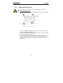
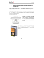
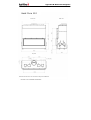
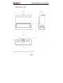
Installation/User Manual
Product
Product group
Application
Models
Heat Pure
Wood burning fireplaces with lifting door
Open and closed
45, 60, 65 3S, 70, 71, 85, 90R, 90L, 100,
105, 105 T, 110, 120
Version
Language
December 2010
English
Preface
Preface
Congratulations on purchasing your Kal-fire fireplace.
This manual describes the installation, daily use and maintenance of all
the fireplaces from the Heat Pure serie. Read this manual carefully before
installing and using the Heat Pure.
Please complete the proof of guarantee (appendix C) and keep it with the
invoice to verify the purchase date.
Always keep this manual close to your Heat Pure
An authorised installer will install the Heat Pure fireplace in compliance
with the national or local applicable regulations. Check the Heat Pure for
transport damage upon delivery. Report any transport damage to the
supplier immediately. The supplier cannot be held responsible for any
damage as a result of faulty installation.
In case any problems occur or if you have any questions concerning the
operation of your Heat Pure, please contact your dealer. Your dealer is
also the person to contact during the duration of the guarantee period.
Kal-fire has installed a telephone helpdesk, to support the technical
department of her dealers, to make sure your dealer will be able to
advise you in a professional way.
All rights reserved. Nothing from this manual may be copied, distributed or translated into
other languages, partly or wholly, without prior written permission from Kal-fire. Kal-fire
reserves the right to modify this manual without notice. Kal-fire can give no guarantee,
neither implicit nor explicit, for this manual. All risks are for the user.
Copyright © 2010 Kal-fire B.V.
Belfeld, the Netherlands
Table of contents
1 Introduction
2 Safety
1 2 3 Mounting and installation
9 2.1 2.2 2.3 2.4 CE-marking ..................................................................... 2 Safety instructions installer ................................................ 2 Safety instructions user ..................................................... 3 Safety precautions ............................................................ 4 3.1 Check before building in/mounting ...................................... 9 3.2 Check flue ..................................................................... 11 3.3 Placing the appliance....................................................... 12 3.4 Supply of combustion air ................................................. 15 3.5 Supply of convection air .................................................. 18 3.6 Chimney/flue connection ................................................. 21 3.7 Mounting the demper ...................................................... 25 3.8 Adjusting the feet ........................................................... 25 3.9 Baffle plate .................................................................... 29 3.10 Finish Heat Pure 65 3-sided ............................................. 34 4 Preparing for use
38 5 Lighting the Heat Pure
40 6 Maintenance
52 7 Trouble shooting
58 4.1 Type of wood ................................................................. 38 4.2 Storing the wood ............................................................ 39 4.3 Ventilation ..................................................................... 39 5.1 5.2 5.3 5.4 5.5 5.6 5.7 Lighting the Heat Pure for the first time ............................. 40 Opening the door............................................................ 40 Air regulation ................................................................. 41 Using the Heat Pure with an open or closed door ................. 42 Igniting the Heat Pure ..................................................... 43 Optimal heat output ........................................................ 47 Operation the demper (optional) ....................................... 51 6.1 6.2 6.3 6.4 Keeping clean panes ....................................................... 52 Cleaning the pane........................................................... 52 Cleaning the grate .......................................................... 56 Maintenance .................................................................. 57 APPENDIX A: EG-declaration of compliance
APPENDIX B: Dimension diagrams
APPENDIX C: Guarantee
1. Introduction
1
Introduction
The wood burning, built in fireplace you have purchased from the Heat
Pure line manufactured by Kal-fire, is guaranteed to provide a lifetime of
heating satisfaction.
The Heat Pure line has the following models:
•
Heat Pure 45
•
Heat Pure 60
•
Heat Pure 65 3 sided (65 3S)
•
Heat Pure 70
•
Heat Pure 71
•
Heat Pure 85
•
Heat Pure 90 corner right (90R)
•
Heat Pure 90 corner left (90L)
•
Heat Pure 100
•
Heat Pure 105
•
Heat Pure 105 tunnel (105T)
•
Heat Pure 110
•
Heat Pure 120
Symbols used
In this manual Kal-fire uses a number of symbols. These symbols
indicate possible damage to the product and/or a life threatening
situation, if the procedures are not observed and followed carefully.
Warning of danger.
Warning of fire hazard through the presence of flammable
substances or a warning of high temperatures.
1
2. Safety
2
Safety
2.1
CE-marking
The appliance has been approved according to the CE standard EN13229-A2.
Every appliance that leaves the factory has been tested for functionality
according to the Kal-fire quality standards.
The national Building Regulations, Fire Regulations and the municipal
regulations apply to this product.
2.2
Safety instructions installer
•
•
•
An authorised installer will connect the Heat Pure in
compliance with the national and/or local applicable
regulations.
Check if the Heat Pure functions correctly immediately after
the installation.
Take the necessary preventive measures, by using noncombustible material, in order to prevent overheating of
floor, boards or walls close to the Heat Pure.
2
2. Safety
2.3
Safety instructions user
•
The Heat Pure wood fire is only intended for use as an
additional heat source.
•
Careful! The exterior of the fireplace can become hot during
use.
1
2
4
3
•
•
•
Nr. 1: The distance between any built-in furniture and the
fireplace, should be at least 5 cm.
Nr. 2: The distance between any wall-, floor- and /or ceiling
material should be at least 1 cm.
Nr. 3+4: Make sure that curtains, furniture and/or other
combustible materials are at least 100 cm removed from the
Heat Pure. If a fireguard is used, this distance must be at
least 40 cm.
3
2. Safety
2.4
Safety precautions
•
•
•
Insulation material must comply with the national
applicable quality standards; this material should,
amongst others, be resistant to high temperatures
(minimum 700 °C), in order to avoid strong odour
development during combustion.
Use ceramic fibre panels or hard panels made from mineral
wool to prevent loose particles of insulation material
circulating in the convection system.
Prevent any insulation material covering the convection air
inlet. Attach the insulation material firmly, to prevent it from
slipping.
4
2. Safety
Table 1: Prescribed insulation thickness to combustible materials
Inspection
Mineral wool
(AGI Q 132)
Side panel (cm)
Roof (cm)
Base (cm)
Rear panel (cm)
Side panel (cm)
Roof (cm)
Base (cm)
Rear panel (cm)
Side panel (cm)
Roof (cm)
Base (cm)
Rear panel (cm)
Side panel (cm)
Roof (cm)
Base (cm)
Promasil
Rear panel (cm)
Heat
Pure
Isorath 1000
45
5
5
9
*
2,6
2,7
5,3
*
2,0
2,1
4,1
*
5
5
9
*
60
10,6
10,5
9
*
8,7
8,6
7,4
*
6,7
6,7
5,7
*
11
11
10
*
65 3Z
5
5
9
*
2,6
2,7
5,3
*
2,0
2,1
4,1
*
5
5
9
*
70
10
10
9
*
2,6
2,7
5,3
*
2,0
2,1
4,1
*
5
5
9
*
71
13,5
10,1
11,9
*
11,0
8,3
9,7
*
8,6
6,4
7,6
*
14
14
13
*
85
15,5
12,3
11,3
*
12,7
10,1
9,2
*
9,9
7,8
7,2
*
16
13
12
*
90R/L
5
5
9
*
2,6
2,7
5,3
*
2
2,1
4,1
*
5
5
9
*
100
10
10
9
*
2,6
2,7
5,3
*
2
2,1
4,1
*
5
5
9
*
105
15,5
13,5
12,1
*
12,7
11,0
9,9
*
9,9
8,6
7,7
*
16
14
13
*
105T
10
-
9
*
2,6
-
5,3
*
2
-
4,1
*
5
-
9
*
110
9,4
8,4
9,3
*
7,7
6,9
7,6
*
6,0
5,3
5,9
*
10
9
11
*
120
9,4
8,4
9,3
*
7,7
6,9
7,6
*
6,0
5,3
5,9
*
10
9
11
9,4
Type
The floor, on which the Heat Pure is placed, must be
made from non-combustible material, as hot ashes and
sparks may fall onto the floor.
5
2. Safety
2.4.1
Installation of the Heat Pure 45, 100 and Heat Pure 105
tunnel in combination with combustible materials (e.g.
a wooden wall)
When installing the Heat Pure 45, the Heat Pure 100 and the Heat Pure
105 tunnel pay attention to the distance to combustible building
materials:
Combustible building materials behind (and in the case of the HP 45 next
to, if the appliance is built into an alcove) must be shielded/insulated as
shown in the drawing below.
Heat Pure 45 and 100
Combustible
material
Combustible
material
Insulation
Insulation
Combustible materials must be
shielded by insulation material
with a minimum thickness of 5
cm. The distance from the back of
the Heat Pure to the insulation
material must be a minimum of
10 cm.
The distance of 10 cm to the insulation must
also be observed for combustible material
within the housing/cladding of the built in
appliance.
6
2. Safety
Heat Pure 105 Tunnel
Combustible material
Combustible materials must be
shielded by insulation material
with a minimum thickness of 10
cm. The distance from the back
of the Heat Pure to the
combustible material must be a
minimum of 30 cm.
Insulation
Ensure that curtains, furniture and/or other combustible materials are at
a distance of minimum 150 cm from the appliance.
* The floor the Heat Pure is placed on must be made of noncombustible materials. The (combustible) floor in front of the
door opening must be protected (30 cm on both sides and 50
cm in front of the appliance).
2.4.2
Prescribed materials
Insulation
Use mats, plates or strips made from silicate insulation materials (stone,
clinkers, ceramic fibres); construction class A1 according to DIN 4102
Part 1, with an upper limit temperature of at least 700°C, tested
according to DIN 52271 and a nominal density of 80 kg/m.
These materials need to have a corresponding insulation material
registration number, according to AGI-Q 132. This number may not
include the combination “99”.
7
2. Safety
For as far as this insulation layer is not kept away from walls, claddings
or adjoining plates, attachments must be mounted at a mutual distance
of max. 33 cm.
Other insulation materials, consisting of, for example, covering concrete
or mineral base materials, must have a General Urban Development
Permit of the German Institute of Building Technology (DIBt). For further
details, see DIN 18895 resp. EN 13229/DIN 18160.
Replacement insulation materials have various heat index values,
depending on the thickness of the insulation material. The required
thickness of the insulation material can be calculated from the graph
delivered by the manufacturer.
Some heat insulation materials can be used for preconstruction and heat
insulation, in order to considerably reduce the built-in depth. Cover heat
insulating materials made from stone and clinker fibre so they are not
subject to wear, otherwise loose particles may be blown by the airflow
into the mounting area. Other heat insulation plates may be supplied
wear proof from the factory.
Floors
The floor, on which the Heat Pure is placed, must have sufficient load
bearing capacity (for the weight of the Heat Pure, see table 4).
8
3. Mounting and installation
3
Mounting and installation
3.1
Check before building in/mounting
3.1.1 Heat Pure 45, 60, 70, 71, 85, 100, 105, 105T, 110, 120
1.
2.
3.
4.
5.
Check immediately upon arrival, if the products supplied are
complete and undamaged. Report any damaged or missing items to
the supplier immediately.
Remove the transport security (screws with yellow sticker on the
front of the convection casing).
Check the following parts for correct working:
- Lifting door up and down
- Forward tilting action of door for cleaning
- Air control
- Adjustment feet
- Any demper with control button (accessories)
- Any aeration valves (accessories)
Hand the installation/users manual personally to the user of the Heat
Pure.
Test the internal fresh air valve for correct working. This valve is
situated on the rear of the Heat Pure, behind the fresh air
connection. When the door is closed, the fresh air flows into the
combustion chamber via the air slide valve. When the door is
opened, the fresh air flows into the combustion chamber via the
convection casing and outlet openings.
9
3. Mounting and installation
3.1.2 Heat Pure 65 3-sided and Heat Pure 90 corner
1.
2.
Check immediately upon arrival if the products supplied are
complete and undamaged. Report any damaged or missing items to
the supplier immediately.
Remove the transport security (Two screws in the convection duct
with yellow sticker on the rear of the convection casing).
Heat Pure 90 corner
Heat Pure 65 3-sided
3.
4.
5.
Check the following parts for correct working:
- Lifting door up and down
- Opening and closing the design doors
- Forward tilting action of door for cleaning
- Air control
- Adjustment feet
- Any demper with control button (accessories)
- Any aeration valves (accessories)
Hand the installation/users manual personally to the user of the Heat
Pure.
Test the internal fresh air valve for correct working. This valve is
situated on the rear of the Heat Pure, behind the fresh air
connection. When the door is closed, the fresh air flows into the
combustion chamber via the air slide valve. When the door is
opened, the fresh air flows into the combustion chamber via the
convection casing and outlet openings.
10
3. Mounting and installation
3.2
Check flue
In order to guarantee correct functioning, we advise you to test/ignite
the Heat Pure at the earliest possible opportunity (before it has been
completely built-in) (see Chapter 5 Lighting the fireplace). Why?
•
•
•
This will allow you to decide if an external demper is necessary.
The enamel can also cure before the surround is finished. Allowing the
enamel to cure will also cause less nuisance for the end user.
This gives you the chance to find out in an early stage, whether or not
the fireplace-flue combination is working correctly.
Checklist (to be executed) when using the fireplace
1.
2.
3.
4.
Check the flue for proper functioning; minimum required draught
(suction) is 12 Pa.
Test the air slide valve for proper functioning; this will work after
the fire has burnt for 50 minutes: (see chapter 3.3.1)
- extreme right position = maximum supply of combustion air
- extreme left position = air supply closed; the flames will slowly
extinguish.
If the flames do not react, or do not react enough, to the change in
the air slide position, it may be worthwhile considering installing an
external demper on the Heat Pure.
After a while close all windows and doors and ensure that all
appliances that remove air from the home, such as cooker hoods,
fans etc. are switched off. Check if the appliance can be used with
an opened door (no smoke trickles back into the room). (see
chapter 3.3)
Use a little smoke to check for correct supply and exhaust of
convection air.
11
3. Mounting and installation
3.3
Placing the appliance
The appliance may not be placed in the following situations:
•
•
•
•
in stairwells, with the exception of buildings with no more
than two dwellings;
in entrance halls with public access;
in rooms where flammable or explosive substances or
mixtures are processed, stored or manufactured;
in rooms or dwellings where air is extracted by airconditioning or with air heating using fans, with the
exception of the following cases where a risk free
functioning of the Heat Pure is safeguarded:
- the installation only circulates air in the room;
- the installation has reliable safety precautions, so that
over pressure is automatically created in the room where
the Heat Pure is installed;
- the combustion air flow of the Heat Pure and the volume
flows of ventilating installations in the room and the
rooms connected by ventilation ducts, create an under
pressure that remains below 0.04 mbar. ATTENTION: This
situation must also be safeguarded if easily accessible
control equipment used for the ventilating installation is
moved or removed.
12
3. Mounting and installation
3.3.1
Working combustion air
If used with a closed door, the Heat Pure
takes the combustion air directly from
the connection at the rear (A) or base
(A’) of the Heat Pure. This combustion
air is guided into the combustion
chamber via de air control (B) and the
primary thermostat (C), where it is used
as primary or secondary combustion air.
Primary combustion air (P)
The thermostat regulates this air flow
automatically. When the Heat Pure is
cold the thermostat ensures that air
enters the combustion chamber via the
lower spoiler. As the Heat Pure warms
up, the air flow will gradually decrease.
After approximately 50 minutes, the Heat
Pure is so warm, that this air flow stops
altogether.
The primary air control is 100%
automatic and cannot be influenced by
yourself.
Secondary combustion air (S)
The air flow is regulated manually via the
operating feature to the right of the
appliance.
Via risers to the left and right of the
combustion chamber, this air is warmed
up and guided to the combustion
chamber via the upper spoiler.
The secondary air flow is used to
regulate the flames and to keep the glass
door clean. This air flow may therefore
never be completely closed off.
13
3. Mounting and installation
If used with an open door, the air need of
the Heat Pure changes. The opening at
the front will cause large volumes of air
to be sucked into the appliance. This air
will be taken from the room the appliance
is installed in.
With an opened door, the built-in valve
ensures that the passage to the
combustion chamber is closed (see
figure). The connected air is re-routed to
the convection casing, where the air is
warmed before it flows into the room.
This air then becomes available in the
room where the appliance is installed so
it can be used in the combustion process.
Detail ’’valve open’’
Detail ‘‘valve closed‘‘
14
3. Mounting and installation
3.4
Supply of combustion air
The appliance must have enough outside air to ensure problem
free ignition. If lower values are established based on the
calculated volume of combustion air, building in the appliance is
for the risk of the installer.
The Heat Pure has a built-in air supply valve; in normal situations no
extra air valve is required. In situations where the side gable is subjected
to frequent high winds or where there are large indoor/outdoor pressure
differences, it is advisable to mount an extra air valve.
In that case the valve must be clearly marked to indicate the open and
closed position. Inform the users about the function and working of the
valve(s).
Some air valve manufacturers use plastic sleeves. Mount these
outside the heat radiation range of the Heat Pure.
Ensure that the fresh air actually is outside air. For example, if
the combustion air originates from a cellar, this cellar must have
sufficient air vents to ensure that any extracted air is replaced
by fresh, outside air.
Ensure that the gratings are placed so, that they cannot become
blocked.
15
3. Mounting and installation
3.4.1
Fresh air connection base or rear
(Heat Pure 45, 60, 70, 71, 85, 90R, 90L, 100, 105, 105T,
110, 120)
The standard for the Heat Pure, is that
the fresh air connection is situated on
the rear. This connection can be
relocated to the base.
Method
1. Demount the connecting collar at
the rear of the Heat Pure.
2. Demount the closing plate at the
base of the Heat Pure. Mount the
closing plate in the former position
of the connecting collar.
3. Mount the connecting collar on the
base of the Heat Pure in the former
position of the closing plate.
3.4.2 Fresh air connection Heat Pure 65 3-sided
The Heat Pure 65 3-sided will be
installed with at least 2 fresh air
connections (2x Ø150 mm).
16
3. Mounting and installation
3.4.3
Fresh air connection without connecting collar
(Heat Pure 45, 60, 70, 71, 85, 100, 105, 105T, 110, 120)
If there is not enough space for the
connection collar, you can demount this
and the air connection using a built
construction. In this case, the Heat
Pure is positioned on or against an
opening for fresh air. Use a ceramic
cord to seal off the transition between
the Heat Pure and the constructed
opening. (Available as an option)
Examples:
• The Heat Pure is positioned against
an opening to a cellar.
• The Heat Pure is positioned against
an outside wall, which has an
opening to the outside air.
Kal-fire connection kit (optional)
• a ceramic cord to fill gaps of max. 2 cm.
• metal strips to attach the cord to the Heat Pure.
17
Ceramic cord
3. Mounting and installation
3.5
Supply of convection air
The Heat Pure is surrounded by a
convection casing, that warms up the
room in a constantly pleasant and
efficient manner.
For this system to operate to its
maximum effect, a convection set is
required.
This optional convection set consists
of:
Heat Pure 45 and 60
• 4 flexible aluminium hoses Ø150 mm 1.25 m: 2 hoses of 2.5 m which
must be divided in half, in order to get a total of 4 hoses.
• 8 clamping strips.
• 4 gratings: outer dimensions 20 x 20 cm, recess dimension 16.5 x
16.5 cm, with connection collar Ø150 mm.
• Mantel iron; this must be sawn to the correct size.
• Roll of felt to create an expansion joint between the metal of the
mantel iron and the surround.
Heat Pure 65 3-sided, 90R and 90L
• 4 flexible aluminium hoses Ø150 mm 1.25 m: 2 hoses of 2.5 m which
must be divided in half, in order to get a total of 4 hoses.
• 8 clamping strips.
• 4 gratings: outer dimensions 20 x 20 cm, recess dimension 16.5 x
16.5 cm, with connection collar Ø150 mm.
For the Heat Pure 65 3-sided and the Heat Pure 90 corner models, the
mantel iron and roll of felt should be ordered separately, it’s not included
in the convection set.
This convection set is ordered separately to the Heat Pure. Instead of a
grating, openings (for example recessed plinths) can be used. Do not
reduce the convection openings.
Place all of the gratings / openings, both upper and lower, to facilitate
the natural circulation. The gratings / openings should be situated in the
same pressure area (the same room) as the Heat Pure.
18
3. Mounting and installation
Heat Pure 70, 71, 85, 100, 105, 105T, 110 and 120
• 8 flexible aluminium hoses Ø150 mm 4x 1.25 m long and 4x 0.62 m.
2 hoses of 2.5 m which must be divided in half, in order to get a total
of 4 hoses and 1 hose of 2.5 m which must be divided into 4.
• 16 clamping strips.
• 4 gratings: outer dimensions 35 x 20 cm, recess dimension 33 x 16.5
cm, with 2 connection collars Ø150 mm each.
• Mantel iron; this must be sawn to the correct size.
• Roll of felt to create an expansion joint between the metal of the
mantel iron and the surround.
Method when using gratings
Ensure that, at the base, there is sufficient supply for the cold convection
air from the room (see table below).
At the top connect the gratings to the outlet openings of the warm
convection air (see table below).
Table 2: Through put openings for convection air
Inlet
convection air
2x Ø150 mm
Heat Pure 65 3S, 70, 71, 85,
90R, 90L, 100, 105, 105T,
110, 120
4x Ø150 mm
355 cm2
705 cm2
Outlet
convection air
2x Ø150 mm
4x Ø150 mm
Heat Pure 45, 60
2
705 cm2
355 cm
Attention! When mounting the gratings, ensure they are placed in such a
position, that they cannot become blocked.
Method when using openings
If you do not want to use gratings, openings at the top and base of the
surround (chimneybreast) are also sufficient. For through put openings,
see Table 2. These openings serve the same function as the gratings and
supply and extract the convection air. We advise you, to place tubes or
hoses on the outlet openings. This makes the convection system (just a
little) more powerful and the heat is guided more easily to the openings.
If you do not use the recommended convection set, this may
damage the Heat Pure by overheating. The result may be soiled
walls and ceilings in the room. There is always a risk of
discolouration to walls and ceilings, but this risk can be
considerably reduced, by correctly ventilating the room.
19
3. Mounting and installation
Mount the gratings at a distance of at least 30 cm from the
ceiling or wall. Ensure there are no flammable materials closer
than 30 cm next to and 50 cm above the gratings.
20
3. Mounting and installation
3.6
Chimney/flue connection
The Heat Pure is connected to an existing flue. The operational height of
the flue must be minimum 4.5 meter (draught 12 Pa), calculated from
the point at which the flue duct is joined to the Heat Pure.
Take local legislation and environmental factors into account.
Table 3: Chimney/flue diameter and firebox per model
Firebox
(in mm)
Width/height
Firebox (cm2)
Minimum fresh
air supply
Flue
Ø (mm)
Type 45
415 / 454
1884
1x Ø 150 mm
150
Type 60
545 / 470
2560
1x Ø 150 mm
180
270 / 460 (2x)
681 / 460
4323
2 x Ø 150mm
250
305/665
2028
2 x Ø 150 mm
180
Type 71
655 / 580
3800
2 x Ø 150 mm
250
Type 85
795 / 360
2860
2 x Ø 150mm
200
Type 90R/L
870 / 460
390 / 460
5796
2 x Ø 150mm
250
Type 100
570/ 926
5278
2 x Ø 150mm
250
Type 105
995 / 440
4380
2 x Ø 150mm
250
995 / 440(2x)
4380(2x)
2 x Ø 150mm
250
Type 110
1045 / 340
3555
2 x Ø 150mm
250
Type 120
1145 / 340
3895
2 x Ø 150mm
250
Heat Pure
Type 65 3Z
Type 70
Type 105T
21
3. Mounting and installation
If you want to use a flue diameter that differs from those shown in table
3, use the formula below to calculate a possibly smaller diameter.
F sch
=
F
so
H
× e
sch
Fsch
Fso
Hsch
e
flue section in cm2
surface firebox in cm2
height of flue in metre measured from the upper
side of the Heat Pure
influence factor between 0.2 and 0.6 determined
by the flue quality: 0.2 with a perfect flue, straight
above the Heat Pure; 0.6 with connection less
than 45°.
Permitted reduction:
- flue Ø150 Æ reduction not permitted
- flue Ø180 Æ maximum reduction 30 mm
- flue Ø200 Æ maximum reduction 20 mm
- flue Ø250 Æ maximum reduction 50 mm
After reducing the flue, it is no longer possible to use the Heat
Pure as an open fire place.
Reduction is permitted immediately behind the demper/
connection collar, but not any deeper into the flue. At doubt,
always use the connection diameter indicated on the Heat Pure.
•
•
•
•
•
Avoid horizontal runs; one extension may be placed with
adjustable elbows with maximum one change of direction of
45°.
Kal-fire advises you to insulate the flue; this will reduce the
risk of the smoke condensing and will improve the draught.
Use the Kal-fire stainless steel insulated flue duct for this
purpose.
Kal-fire advises you not to use larger flue diameters than the
connection present on the Heat Pure. Using a larger flue
diameter can result in the following problems:
Too fast and uncontrolled combustion;
Irregular flames;
Reduced heat output.
Use a draught hood if there is a flue with a (too) strong
draught. If the flue has too much upward draught, this may
result in a too quick, uncontrolled combustion, irregular
flames and rapid soiling of the glass door.
Use of different flue diameters to those indicated, is entirely
for the risk of the installer; when the door is opened, smoke
may escape back into the room or it may be more difficult to
ignite the Heat Pure.
22
3. Mounting and installation
•
•
3.6.1
Take factors in the surrounding environment into account
which could cause a strong draught in the flue. For example,
frequent high winds, which require a demper to be mounted.
Pay attention that it is also possible to sweep the chimney in
the connection piece.
Rear connection (Heat Pure 45, 60, 70, 71, 85, 100, 105,
105T, 110, 120)
The Heat Pure is delivered as standard, with the flue exit connection on
the top of the appliance. This connection can be converted to create a
flue exit connection at the rear of the appliance.
1
4
2
3
6
5
Figure 1 Converting a top flue exit into a rear flue exit (6 steps)
23
3. Mounting and installation
1.
2.
Demount the upper part of the convection casing.
The connection piece is now visible and the four bolts can be
unscrewed.
Turn the connecting piece 180°.
Press the punched cover out of the convection casing; this cover is
used to close off the upper connection.
Mount the upper part back onto the Heat Pure.
Place the cover on the opening on the top.
Continue with the connection of the Heat Pure.
3.
4.
5.
6.
7.
Attention:
• Make sure that all the horizontal parts of the rear connection can be
reached for cleaning.
• The horizontal part may be maximum 50 cm.
3.6.2
Reducer ring
The Heat Pure is delivered as standard with a reducer ring. This ring can
be used to connect various flue systems to the Heat Pure.
Figure 2 Reducer ring
Table 4: Diameter chimney connection collar
Connection collar
Heat Pure (mm)
A inn.
(mm)
B inn.
(mm)
C inn.
(mm)
45
Ø148 ±2
Ø156 ±1
Ø136 ±1
Ø152 ±1
60, 70
Ø178 ±2
Ø186 ±1
Ø166 ±1
Ø182 ±1
85
Ø198 ±2
Ø206 ±1
Ø186 ±1
Ø202 ±1
65 3S, 71, 90R,
90L, 100, 105,
105T,110, 120
Ø248 ±2
Ø256 ±1
Ø236 ±1
Ø248 ±1
Heat Pure Type
24
3. Mounting and installation
3.7
Mounting the demper
The Heat Pure is delivered as standard without a demper. A demper can
be used to influence the degree of draught (suction) in the flue. With the
Heat Pure an external demper can be added. If there is too much suction
in the flue, we advise you to use a demper. The amount of draught can
be tested when you ignite the fire to test the operation of the appliance.
Pay extra attention to this aspect, if the flue is longer than 7 metres.
Normally the Heat Pure can be controlled well using the air regulation
(see section 5.3).
Attention
•
Make sure that the position of the demper is visible for the end user.
For this purpose most of the operating knobs have a position
indication (Open = Auf or + , Closed = Zu or -).
•
Check the functioning of the demper before completing the
installation of the Heat Pure.
•
Make sure that the end user is familiar with way the demper
functions.
3.8
Adjusting the feet
Heat Pure 45, 60, 70, 71, 85, 100, 105, 105T, 110, 120
Rough adjustment
Unscrew the two bolts and roughly
set the height.
Range 38 cm. Do not forget to
place the two bolts back.
Fine adjustment
Screw the adjustment foot bolt to
set the precise height. Range 5 cm.
Use this method to set the Heat
Pure perfectly level.
25
3. Mounting and installation
Heat Pure 65 3–sided, 90 corner model
Fine adjustment
Screw the bolt at the adjustment foot to set the precise height. Range 5
cm. Use this method to set the Heat Pure perfectly level.
26
3. Mounting and installation
Fireplace surround
Materials with the following characteristics can be used to create the
surround around the Heat Pure:
−
resistant to high temperatures, minimum 700 °C.
−
free from materials which can cause fumes and odour nuisance.
−
dimensionally stable, even after lengthy exposure to high
temperatures.
1. The surround must have no direct connection to the Heat
Pure; it must be self supporting.
2. Seal the joints between the Heat Pure and the surround,
using heat resistant glass fibre or ceramic cord.
3. Use the Kal-fire mantel iron for easy and stable mounting of
the span above the door of the Heat Pure. Never attach this
mantel iron to the actual Heat Pure, but to the side of the
surround or use tie rods to attach it to the ceiling or wall.
4. Ensure that the thickness of the surround above the door of
the Heat Pure does not exceed 11 cm, otherwise the Heat
Pure will be too deeply recessed and it will be difficult to
operate/clean the door.
5. Finish the surround using materials that do not contain any
plastic substances. High temperatures may cause plastic to
discolour.
6. Before completely closing off the surround, ensure that the
inside of the surround is clean and free of dust. Preferably
use a vacuum cleaner to clean the inside of the surround. If
you fail to do his, particles of dust may cause problems in
the air flow of the convection system.
7. The Heat Pure is surrounded by a metal strip which
facilitates the join between the surround and the Heat Pure.
These metal strips can be hidden from view on the front; all
the lines of the surround then merge into the finishing strips.
The side strips can be demounted inwards, so the guide can
be accessed in the event of maintenance.
27
3. Mounting and installation
3.8.1 Practical examples of connection: combustion air and convection
Situation 1 - Recommended situation
The combustion air is connected directly to
the Heat Pure from outside. The outside air is
not in contact with the room the appliance is
installed in or with the chimneybreast. The
convection system is also connected directly
to the Heat Pure. There are no open
connections between the interior of the
chimneybreast and the room in which the
appliance is installed.
Situation 2:
The combustion air is connected directly to
the Heat Pure from outside. The outside air is
not in contact with the room the appliance is
installed in or with the chimneybreast. The
convection system is only in contact to the
room in which the appliance is installed.
Situation 3:
The combustion air cannot be connected
directly to the Heat Pure; this air must be
taken from the room the appliance is installed
in. This mainly occurs in an existing situation,
in which the combustion air can only be taken
from the room the appliance is in.
The convection system must then be
physically separated from the combustion air;
connect the lower and upper convection
gratings directly to the Heat Pure. The
combustion air reaches the Heat Pure through
extra openings in the chimneybreast. See
Technical Specifications (table 4) for the
through put of these openings.
The convection connections at the top of the appliance must be
connected at all times.
28
3. Mounting and installation
3.9
Baffle plate
Heat Pure 45
The Heat Pure has a removable baffle plate.
This baffle plate is situated above the smoke
hood just below the heat exchanger. The
baffle plate ensures optimal an combustion.
In the following situations, it may be
necessary to remove the baffle plate(s) or
decrease it’s the size.
•
Bad exhaust of the flue gasses
•
Condensation in the flue duct
If necessary, you can adjust the baffle plate
as follows:
1. Remove the baffle plate and see if this
solves the problem. If the problem still
occurs, then something else is the cause.
If removing the plate solves the problem,
proceed with the next step.
2. Use a saw or knife to cut away a strip of 1
cm wide at the front of the baffle plate.
Do not remove too much. The baffle plate
must still be able to rest on the bracket. A
maximum of 6 cm can be cut away from
the baffle plate.
3. In certain situations it may be necessary
to remove the baffle plate completely.
29
Baffle plates
3. Mounting and installation
Heat Pure 60, 70, 71, 85, 105, 110 120
The Heat Pure has a removable baffle plate.
This baffle plate is situated above the smoke
hood just below the heat exchanger. With
the larger Heat Pure Models this plate
consists of several parts.
The baffle plate ensures an optimal
combustion.
In the following situations, it may be
necessary to remove the baffle plate or
decrease it’s the size.
•
Smoke return when the Heat Pure starts
•
Condensation in the flue duct
If necessary, you can adjust the baffle plate
as follows:
Baffle plate
1. Remove the baffle plate and see if this
solves the problem. If the problem still
occurs, then something else is the cause.
If removing the plate solves the problem,
proceed with the next step.
2. Use a saw or knife to cut away a strip of 1 cm wide at the front of
the baffle plate. Do not remove too much. The baffle plate must still
be able to rest on the bracket. A maximum of 6 cm can be removed
from the baffle plate.
3. In certain situations it may be necessary to remove the baffle plate
entirely.
30
3. Mounting and installation
Heat Pure 65 3-sided
The Heat Pure 65 3-sided has two removable
baffle plates. These baffle plates are situated
above the smoke hood just below the heat
exchanger.
The baffle plate ensures an optimal
combustion.
In the following situations, it may be
necessary to remove the baffle plate(s) or
decrease it’s the size.
•
Smoke return when the Heat Pure starts
•
Condensation in the flue duct
If necessary, you can adjust the baffle plates
as follows:
1. Remove the lower baffle plate and see if
this solves the problem. If the problem still
occurs, then also remove the upper baffle
plate. If the problem still isn’t solved, then
something else is the cause. If removing the
plate(s) solves the problem, proceed with the
next step.
2.
Baffle plate
Cut away a strip of 3 cm wide, at the front and rear of the baffle
plate. If necessary, do this for both baffle plates.
A 3-sided fireplace is always a more sensitive product than a fireplace
with a door at the front, particularly when used with an open door.
If the Heat-Pure 65-3-sided is used as an open fireplace, some smoke
may flow back into the room- even if both baffle plates have been
removed. This may have a number of causes:
Insufficient pull in the chimney duct,
The air flow patterns in the room where the
3-sided fireplace has been installed,
Too low ignition temperature.
31
3. Mounting and installation
Heat Pure 100
The Heat Pure has a removable baffle plate.
This baffle plate is situated above the smoke
hood just below the heat exchanger. The
baffle plate ensures optimal an combustion.
In the following situations, it may be
necessary to remove the baffle plate(s) or
decrease it’s the size.
•
Bad exhaust of the flue gasses
•
Condensation in the flue duct
If necessary, you can adjust the baffle plate
as follows:
1. Remove the baffle plate and see if this
solves the problem. If the problem still
occurs, then something else is the cause.
If removing the plate solves the problem,
proceed with the next step.
2. Use a saw or knife to cut away a strip of 1
cm wide at the front of the baffle plate.
Do not remove too much. The baffle plate
must still be able to rest on the bracket. A
maximum of 6 cm can be cut away from
the baffle plate.
3. When used as an open fire place, the
baffle plates should be removed
completely.
32
Baffle plates
3. Mounting and installation
Heat Pure 105 Tunnel
The Heat Pure 105 Tunnel has several
removable baffle plates. These baffle plates
are situated above the smoke hood just
below the heat exchanger. The baffle plate
ensures an optimal combustion.
In the following situations, it may be
necessary to remove the baffle plate or
decrease it’s the size.
•
Smoke return when the Heat Pure starts
•
Condensation in the flue duct
If necessary, you can adjust the baffle plate
as follows:
Baffle plates
1. Remove all baffle plates and see if this
solves the problem. If the problem still
occurs, then something else is the cause.
If removing the plate solves the problem,
proceed with the next step.
2. Use a saw or knife to cut away a strip of 1 cm wide at the front of
the baffle plate. Do not remove too much. The baffle plate must still
be able to rest on the bracket. A maximum of 6 cm can be removed
from the baffle plate.
3. In certain situations it may be necessary to remove the baffle plate
entirely.
The Heat Pure 105 tunnel is not suitable to be used as an
open fire place.
33
3. Mounting and installation
3.10 Finish Heat Pure 65 3-sided and Heat Pure 90 corner
Finish upper side
Space of min. 2mm
The surround above the Heat Pure 65 3-sided and Heat Pure 90
corner, must have at least 2 mm of play, in relation to the trim
above the door.
Finish side
Cut through C-C
Surround
Make sure the surround / plastering
is not sticking out with respect to this
converted side. This will prevent that
the little doors on both sides of the
Heat Pure 65 3-sided and 90 corner
are obstructed.
34
3. Mounting and installation
Finish front
The front of the Heat Pure 65 3-sided and 90 corner can be finished in
two ways:
1.
Mount the platform under the steel design trim.
Steel
design trim
Platform
The platform may not touch the steel design trim.
35
3. Mounting and installation
Table 5: Technical data
Heat Pure:
Indication plate
Inspection body
45
60
65 3Z
70
71
85
P8-0632009
EZ/06/1961
/04
P8-2872008
P8-0862009
EZ/06/196
/03
EZ/06/1961
/02
1004
0608
1004
1004
0608
0608
Norm
EN13229
A2
EN13229
A2
EN13229
A2
EN13229
A2
EN13229
A2
EN13229
A2
Output (kW)
4,7 – 9,3
13,0
7,5 -15,0
4,8 –9,7
15,0
13,0
Flue gas mass flow (g/s)
6.8
9,9
12,5
8,6
13,2
10,9
Heat output (%)
86
81
83
84
72
76
Flue gas temperature (°C)
270
251
229
240
328
272
CO at 13%O2 (%)
0,10
0,09
0,12
0,12
0,09
0,12
CO2 content (%)
11.1
10,58
10,2
9,2
9,11
9,24
Dust content
at 13%O2 (mg/nm3)
36
45
19
62
19
16
NOx at 13%O2 (mg/nm3)
150
109
140
105
100
125
CnHm at 13%O2
(mg/nm3)
58
61
100
117
48
63
Min. flue draught (Pa)
12
11,6
12
11
12,2
12,7
Insulation side panel (cm)
(AGI-Q 132, table 1)
5
11
3,3
10
14
13
Insulation rear panel (cm)
(AGI-Q 132, table 1)
5
11
3,2
10
14
16
Insulation base (cm)
(AGI-Q 132, table 1)
0
0
0
0
0
0
Insulation roof (cm)
(AGI-Q 132, table 1)
9
10
6,5
9
13
12
¢150
¢180
¢250
¢180
¢250
¢200
Combustion air
connection (mm)
1x Ø150
1x Ø150
2x Ø150
2x Ø150
2x Ø150
2x Ø150
Convection connection
inlet (mm)
2x Ø150
2x Ø150
4x Ø150
4x Ø150
4x Ø150
4x Ø150
Convection connection
outlet (mm)
2x Ø150
2x Ø150
4x Ø150
4x Ø150
4x Ø150
4x Ø150
180
226
270
210
271
257
Flue connection (mm)
Weight (kg)
36
3. Mounting and installation
Table 5: Technical data
Heat Pure:
90R/L
100
105
105T
110
120
Indication plate
P8-0482010
P8-0662010
EZ/06/1961/
01
P8007/2010
EZ/07/22
13/02
EZ/07/2213/
01
Inspection body
1004
1004
0608
1004
0608
0608
Norm
EN13229
A2
EN13229
A2
EN13229
A2
EN13229
A2
EN13229
A2
EN13229
A2
Output (kW)
7,5-14,9
8,8-17,6
17,0
8,8 – 17,6
16,5
17
14,95
17,34
14,4
20,87
14,4
14,5
Heat output (%)
80
80
75
78
75
75
Flue gas temperature (°C)
241
255
376
275
350
324
CO at 13%O2 (%)
0,1
0,09
0,08
0,10
0.09
0,11
CO2 content (%)
8,6
8,8
10,16
7,4
9,39
8.,63
Dust content
at 13%O2 (mg/nm3)
20
22
65
25
54
44
NOx at 13%O2 (mg/nm3)
138
116
107
150
105
104
CnHm at 13%O2 (mg/nm3)
93
90
30
110
50
70
Min. flue draught (Pa)
13
13
12,2
11
12
12
Insulation side panel (cm)
(AGI-Q 132, table 1)
10
5
14
-
8,4
3,3
Insulation rear panel (cm)
(AGI-Q 132, table 1)
10
5
16
10*
9,4
3,2
Insulation base (cm)
(AGI-Q 132, table 1)
0
0
0
0
0
0
Insulation roof (cm)
(AGI-Q 132, table 1)
9
9
13
9
9,3
6,5
¢250
¢250
¢250
¢250
¢250
¢250
Combustion air
connection (mm)
2x Ø150
2x Ø150
2x Ø150
2x Ø150
2x Ø150
2x Ø150
Convection connection
inlet (mm)
4x Ø150
4x Ø150
4x Ø150
4x Ø150
4x Ø150
4x Ø150
Convection connection
outlet (mm)
4x Ø150
4x Ø150
4x Ø150
4x Ø150
4x Ø150
4x Ø150
320
430
328
435
302
335
Flue gas mass flow (g/s)
Flue connection (mm)
Weight (kg)
* see explanation on page 8
37
4. Preparing for use
4
Preparing for use
4.1
Type of wood
The Heat Pure built-in fireplace is suitable for
burning dry wood. We recommend using only
chopped wood, which has not undergone any
treatment; MDF, stained or coated wood, and
flammable waste should not be used as fuel in the
Heat Pure on environmental grounds and to protect
the working life of the Heat Pure. The most suitable
types of wood are beech, oak and birch.
Dry wood (approximately 15% moisture content) is extremely important
for a good combustion process. If damp wood is used, the ceramic
window pane in the door will become soiled and there is an increased
risk of chimney fire. It will also form an environmental nuisance and a
nuisance to the neighbours as a result of the excessive smoke/odour that
is released (extremely dark smoke). This is why you should always make
sure that dry wood is stored suitably. To obtain the ideal moisture
content of 15%, the chopped wood often needs to dry outside for a
period of 2 to 3 years.
If the Heat Pure is lit with an open door, we advise you to use broadleaf
wood such as oak, beech and birch. These types of wood do not contain
much resin. When burning types of wood that do contain resin, such as
pine and larch and fir, a lot of sparks are released. We also discourage
the use of hardwood. It is better to mix the different types of wood, for
example, by combining broadleaf wood with hardwood. This will benefit
the lifespan of the Heat Pure and will create a more attractive play of
flames.
38
4. Preparing for use
4.2
Storing the wood
All types of wood should be stored for about 2 to
3 years in a dry, protected and well-ventilated
area. For example in a lean-to next to the house.
A cellar or a garage without good ventilation is
not suitable as a storage place for wood. Also, the
wood should be stored chopped; otherwise the
bark will impede the drying process. Wood often
contains insects; therefore do not store the wood
in the living room for lengthy periods.
4.3
Ventilation
The risk of discolouration can be reduced by effective ventilation in the
room where the appliance is installed (see also section 3.5).
Below are some tips, from the Dutch decorative heating guild, to avoid
discolouration:
•
The area in which the Heat Pure is situated must be well ventilated.
•
Minimise the use of candles and oil lamps and keep the wick as short
as possible. These ‘decorative touches’ produce considerable
amounts of soiling and unhealthy soot particles in your home.
•
Wait at least 6 weeks before lighting a newly installed masonry
mantelpiece or after building work. The building moisture must be
allowed to disappear completely from walls, the floor and ceiling.
•
Avoid smoking. Smoking is not only bad for your health, but
cigarette and cigar smoke also contain tar, that will cause deposits
on colder and damp walls when heated.
•
With renovations or new building work, ensure there is extra
ventilation to remove volatile solutions from your home.
39
5. Lighting the fireplace
5
Lighting the Heat Pure
5.1
Lighting the Heat Pure for the first time
When the Heat Pure is lit for the first time, the enamel on the stove will
burn in and cure. This causes nuisance in the form of odour and fumes.
Make sure the room is well ventilated. It is advisable to light the Heat
Pure during the day, and open all doors and windows in order to reduce
the odour nuisance.
Enamel that has not yet cured is particularly sensitive. Avoid
touching the enamelled parts of the fireplace. Leave the door
open, for about 5 cm, the first time the Heat Pure is lit and close
the door after it has cooled down. When heated the enamel is
soft and will stick sooner. If the door does stick to the Heat
Pure, it can be tilted (see section 5.2).
5.2
Opening the door
The Heat Pure is equipped with a lifting door.
To open the door, place the handle in the
opening on the lower right. To do so, use the
short pin, attached to the handle.
Then lift the handle upwards.
The first 3 cm can be quite difficult, because
the door has to be pulled out of the lock.
After this, it will be easier. The door can be
left open in any desired position. The
frameless bottom of the door, always gives
you have an optimum view of the flames.
Operating the air regulation
Operating the door
Figure 3: end of the key
40
5. Lighting the fireplace
5.3
Air regulation
The Heat Pure has two types of air
regulation:
The primary air is regulated automatically
and ensures that the wood is easily
ignited. This creates a glowing bed of
carbonised wood for an optimal
gasification process. After burning for
approximately 50 minutes, this valve
closes automatically, which will produce a
high heat output.
When the primary air valve is closed, the
air enters the combustion chamber
through the top spoiler. This top spoiler
also ensures that the window remains
clean. When the draught in the chimney
exceeds 12 Pascal, and (very) dry wood is
being burned, you will be able to keep the
window clean for a considerable length of
time.
However, soiling can occur on the window
when the fire is smothered by closing the
air regulation.
The flames can be regulated by inserting
the side of the key into the groove
positioned on the right-hand side of the
Heat Pure. Use the right side of the
handle (figure 3). By moving the key to
the left, you will minimise the air supply
to the top spoiler; the fire will burn more
calmly (provided that the primary air
valve has closed automatically). By
moving the key to the right, the air supply
to the fire will increase and the fire will
burn more strongly.
41
5. Lighting the fireplace
5.4
Using the Heat Pure with an open or closed door
The Heat Pure can be used as an (open) fireplace or a stove (door
closed). The main difference, is that each use has a different air
requirement. For this reason, the Heat Pure features a fresh air valve at
the rear of the appliance (patent).
Advantage: The air required by the flue duct to ensure good constant
circulation is always introduced into the Heat Pure or room in the most
efficient and comfortable way. When placing the Heat Pure it is always
important to take heavy air users into account, such as large ventilation
systems and extractor hoods. These products use powerful motors to
extract air, the pressure difference built up naturally by a flue is far less.
Closed door
Open (fireplace) door
When the door is open, the heat output will fall to about 20%. The wood
consumption will increase; as air has unregulated access to the wood.
The advantage is a cosy hearth fire.
• Never leave an open fire burn without supervision; any sparks
could cause a fire.
• Open the demper (if present) completely.
• Only use the Heat Pure as an open fireplace if there is enough
draught in the flue.
• Preferably use the Heat Pure with a closed door. This is better
for the environment and the heat output.
42
5. Lighting the fireplace
5.5
5.5.1
Igniting the Heat Pure
Igniting the Heat Pure 45, 60, 65 3-sided, 71, 90 R/L and
100
Place a couple of large logs on the
base of the appliance and one large
log against the rear wall. Place a
smaller log on top. Place some
firelighters on top.
Place some finely chopped wood onto
the logs. Open the air regulation
completely (position on the extreme
right).
Ignite the firelighters using a long
match. Leave the door slightly open
(1-2 cm) for a couple of minutes.
When there is a glowing bed,
distribute the glowing ashes using
poker. Now add more wood (see
section 5.6).
43
5. Lighting the fireplace
5.5.2
Igniting the Heat Pure 70, 85, 105, 110 and 120
Place a couple of large logs on the
base of the appliance and one large
log against the rear wall. Place two
pieces diagonally on top. Place some
firelighters on the logs.
Place some finely chopped wood onto
the logs. Open the air regulation
completely (position on the extreme
right).
Ignite the firelighters using a long
match. Leave the door slightly open
(1-2 cm) for a couple of minutes.
When there is a glowing bed,
distribute the glowing ashes using
poker. Now add more wood (see
section 5.6).
44
5. Lighting the fireplace
5.5.3
Igniting the Heat Pure 105 Tunnel
Place a log on the base of the
appliance with some finely chopped
wood on both sides.
Place 2 logs diagonally on top of the
wood,
together
with
a
few
firelighters. Use the operating key to
open the air regulation completely.
(position on the extreme right).
When there is a glowing bed,
distribute the glowing ashes using a
poker. Now add more wood (see
section 5.6.
Ignite the firelighters using a long
match. Leave the door slightly open
(1-2 cm) for a couple of minutes.
45
5. Lighting the fireplace
Tips
• Use enough wood to ignite the Heat Pure:
- Heat Pure 45
approx. 2 kg
- Heat Pure 60, 65 3-sided, 85 and 90 R/L
approx. 4 kg
- Heat Pure 71, 100, 105, 110 and 120
approx. 6 kg
• When the fire has been lit, leave the door slightly open (1-2 cm) for a
few minutes; the wood will catch fire more easily and the flue will be
quickly warmed-up.
Do not use white spirits, petrol, oil or other liquid fuels.
Be aware that weather conditions (air pressure, temperature,
wind) can influence combustion.
Minimize these influences by adjusting the secondary air supply.
46
5. Lighting the fireplace
5.6
Optimal heat output
For optimal heat production we advise you to burn wood according to the
instructions below. This will achieve the same performance and emission
values, obtained during inspection of the appliances.
• Ensure a glowing bed is created (see section 5.5)
• Use logs of wood of approximately the same size. The amount differs
per type of Heat Pure. See table below.
Table 5 Instructions for optimal burning per model
Heat Pure:
Weight* per log (g)
Number of logs
Maximum weight* wood per hour
(kg)
Air regulation open (%)
Heat Pure:
Weight* per log (g)
Number of logs
Maximum weight* wood per hour
(kg)
Air regulation open (%)
45
60
65 3Z
70
71
85
850
850
1300
730
1000
850
2
3
3
3
3
3
2,3
4
4
2,2
5
4
100
100
45
75
50
100
90
R/L
850
100
105
105T
110
120
1200
1300
1100
1300
1300
4
3
3
4
3
3
4
3,6
5,7
5
5
5,2
10
60
100
50
100
100
* Weight for beech
47
5. Lighting the fireplace
To get an optimal air mixture, you need to place the logs as follows:
Heat Pure 45
Place the two wood logs in a V shape.
Heat Pure 60 and 71
Position the logs in an A-shape with
the horizontal log at the base.
48
Heat Pure 65 3S, 85, 100*,
105, 110, 120
Position the logs in an A-shape
with the horizontal log on top
of the two vertical logs.
Heat Pure 70
Two logs are 15 to16 cm long.
The third log is 33 cm.
5. Lighting the fireplace
Heat Pure 90R and 90L
Place 4 logs of approx ca. 25cm long in a cross shape in the right or left
side of the fireplace.
Heat Pure 105 Tunnel
Place 4 logs of approx ca. 30cm long in a cross shape in the centre of the
fireplace.
*Heat Pure 100
The length of the logs is approx. 29cm.
The Heat Pure 45 can be used both as an open or closed fireplace.
Remove both baffle plates before using the appliance with the door open,
to enable correct exhaust of the flue gas.
49
5. Lighting the fireplace
Open door use
We advise you to keep the door of the Heat Pure 45 door closed, until
there is a good glowing bed and the Heat Pure 45 is well heated (high
temperature of the skamol plates and in the combustion chamber). This
ensures the flue gas is exhausted correctly.
If the appliance is used with the door open straight away, there is only a
minimum of pull in the chimney. The flue gasses will not be exhausted
correctly, but will flow back into the room.
When the logs have been burnt, position new logs on the glowing bed in
the same way as explained above. Take the amount of wood indicated
per hour into account.
Heat Pure 70
If the flue duct of the Heat Pure 70 has been reduced (from 180 to 150)
the appliance is no longer suitable for use when open. Only open the
door of the firebox if strictly necessary (e.g. to add logs).
Heat Pure 105 Tunnel
The Heat Pure 105 tunnel is not suitable to be used when open. Only
open the door of the firebox if strictly necessary (e.g. to add logs).
5.6.1
Topping up with wood
To maintain optimal heat output, top up the fire with new wood as soon
as the flames have disappeared and the logs are starting to glow (no
smoke development). To add new logs, you need to open the door
slowly, to prevent smoke escaping into the room because of the sudden
draught. Do not add more than 2 to 3 logs (see maximum weight wood,
table 5). When the logs are burning strongly, you can close demper (if
installed) again.
A rule of thumb: 1 kg of wood provides about 4 kW of energy.
The Heat Pure is suitable for discontinuous use. This is achieved by
burning according to table 5.
50
5. Lighting the fireplace
5.7
Operation the demper (optional)
Depending on the situation, an external demper can be connected to the
Heat Pure (see section 3.6). Attention! It is not necessary to install a
demper in all situations! After the installer has installed the demper, you
can operate it using the knob on the side of the surround.
When using an original Kal-fire demper, the letters “Auf or +” on the
knob show the open position. “Zu or -” is the closed position. Set the
required position by turning the knob. The position of the demper
depends on the draught in the flue and the way the appliance is being
used:
When lighting the
fire
demper fully open.
When burning with
closed door
The demper can be closed to 20-50% which will
calm the flames. If you want to top up wood,
open the demper completely, before opening the
door. When the wood is burning to your
satisfaction, you can partly close the demper
again.
When burning with
open door
Fully and permanently open the demper.
51
6. Maintenance
6
Maintenance
6.1
Keeping clean panes
To keep the panes clean:
• Only burn dry wood (with a moisture level of approximately 15% and
stored dry and chopped for 2 years).
• Open the air supply completely (100%).
• Open the demper completely (if present).
• Ensure the flue has a minimum draught of 12 Pa.
6.2
Cleaning the pane
Heat Pure 45, 60, 70, 71, 85, 100, 105, 105T, 110, 120
1. To clean the pane, press the lifting door
down firmly and completely.
2. Place the key in the lock situated in the
centre at the top.
3. Turn the lock to the left until you feel
resistance.
4. The key can also be slotted into the lip
on the upper right and used to pull the
door open.
5. The door can now be tilted forward.
6. Before cleaning the pane, allow the
material to cool down completely, to
prevent any damage. The best way to
clean the glass, is to use the Kal-fire
window cleaner, available at your
dealer.
7. Use a cloth or piece of paper to remove
the worst soiling from the pane.
8. Spray the window cleaner onto a cloth
or piece of paper and wipe the pane
clean. Never spray the window cleaner
straight onto the glass!
52
6. Maintenance
9.
Wipe over the pane with a damp cloth
afterwards, to remove all traces of the
detergent used.
10. The deposits will automatically fall into
the combustion chamber due to the
tilted position of the door. The area in
front of the Heat Pure will be kept
clean.
To close the door again, tilt it back and turn the key to the right. The
Heat Pure will be hermetically sealed again by the three-point closure.
− Ensure that no detergent fluids makes contact with the sealing
cords. This will damage the cords!
− Remove persistent soiling by dipping a damp cloth into the
ash. Rub the glass with the cloth.
− Do not use detergents that contain ammonia. Ammonia will
damage the sealing cords.
− Ensure that no glowing particles come into contact with the
sealing cord. These will damage the cords.
53
6. Maintenance
Heat Pure 65 3-sided
1.
2.
3.
4.
5.
6.
7.
8.
Before you are going to clean the glass,
it has to be completely cooled down, to
prevent damage.
Press the complete lifting door down
firmly.
Open both doors, left and right (see
image).
The closing levers are behind the doors.
Pull these lever forwards; they will lock
in a horizontal position.
The door is released and can be moved
forward (see image). Take hold of the
door on the left and right and gently
pull it forwards.
Use a cloth or piece of paper to remove
the worst soiling from the glass.
Spray the detergent onto a cloth or
piece of paper and wipe the glass clean.
Never spray the cleaning agent directly
onto the glass.
Wipe over the glass with a damp cloth
afterwards, to remove all traces of the
detergent used.
54
6. Maintenance
Heat Pure 90 corner right and left
1.
2.
3.
4.
5.
6.
7.
8.
9.
10.
Before you are going to clean the glass,
it has to be completely cooled down, to
prevent damage.
Press the complete lifting door down
firmly.
To open de door use the lever (see
picture).
Pull down the lever until it is in an
vertical position.
The door is released and can be moved
forward (see image). Take hold of the
door on and gently pull it forward.
Use a cloth or piece of paper to remove
the worst soiling from the glass.
Spray the detergent onto a cloth or
piece of paper and wipe the glass clean.
Never spray the cleaning agent directly
onto the glass.
Wipe over the glass with a damp cloth
afterwards, to remove all traces of the
detergent used.
To close the door, gently push back the
glass. Turn back the lever in its original
horizontal position.
Close the flap (see last picture).
lever
flap
55
6. Maintenance
6.3
Cleaning the grate
Your Heat Pure is suitable for burning dry wood, which burns best in its
own ashes. This combustion leaves very little residual ash (approx. 3 g
per kg wood).
Be careful when you remove the ashes, as they can still glow,
even after 24 hours. Never use a vacuum cleaner without
special accessories, like the ash-clean.
Make sure that the level of ash does not rise above the spoiler.
The spoiler is situated in the frame and ensures correct ignition
of the wood. The opening of the air gauge must never be
obstructed or blocked.
The lower sealing cord must be free of ash, so that the glass is
able to lay against the sealing cord.
TIP: Ash consists largely of minerals, which can be used as a fertiliser in
the garden.
56
6. Maintenance
6.4
1.
2.
3.
4.
5.
6.
Maintenance
The enamelled parts of the Heat Pure can be cleaned using a lintfree damp cloth. Repair enamel and spray cans can be obtained
from your dealer, if the enamel becomes damaged.
The flue/ chimney should be inspected and swept at least once
every year. Do not use steel brushes on a stainless steel flue duct.
Remove the baffle plate before sweeping to remove the soot and to
ensure the plate is not obstructing the passage during sweeping.
Clean the space underneath the Heat Pure via the convection
gratings at the base. Dust can easily collect here, conveyed by the
convection current.
Make sure the cord in the lower frame is free of ash and soiling.
If the cords no longer seal properly, they can be replaced. Contact
your dealer for assistance.
Treat the chain in the lifting door system each year, by spraying it
with Kal-fire lubrication.
The pane is made from special ceramic glass. This should
not be placed in the bottle bank (recycling glass).
Ceramic glass does not melt in the glass oven and will
therefore cause problems in the glass oven. Your ceramic
glass should be returned to your council waste tip so that
it can be recycled appropriately.
Only use Kal-fire spare parts as replacement parts (if necessary).
These parts can be obtained from your trade dealer.
57
7. Trouble shooting
7
Trouble shooting
Dirty pane
¾
¾
¾
¾
¾
¾
¾
¾
Press the door fully downwards, so it is closing properly against the
lower sealing cord.
Check the sealing cord in the door and at the base of the pane for
damage/wear.
Check the moisture content of the wood.
Check that the air vents in the spoilers above and below the window
are blocked.
Burn wood according to the instructions.
Check the corner rubbers for wear.
Check if the tilting mechanism is correctly locked.
Check if the secondary air regulation is in the maximum position to
the right.
Demper is sticking
¾
¾
Check if there is something blocking the demper and remove this, if
necessary.
Check if the flue/ chimney is blocked.
Lifting door moves with difficulty
¾
¾
Clean the guide.
Check if the door cord is sticking against the surround.
Smoke return
¾
¾
¾
¾
¾
Check if the flue/ chimney is blocked.
Ensure that the flue duct is sufficiently warmed up before opening
the lifting door.
Only burn dry wood.
Reduce or remove the baffle plate.
Check that enough fresh air is being supplied.
58
7. Trouble shooting
Fire bricks or skamol plates are broken
¾
Cracks in the inner housing do not influence the operation of the
Heat Pure.
Odour nuisance
¾
¾
¾
¾
¾
¾
When the Heat Pure is used for the first time, a chemical odour is
released due to the enamel being cured;
Check if the flue/ chimney is blocked.
Ensure that the flue duct is sufficiently warmed up before opening
the lifting door.
Check that enough fresh air is being supplied.
Only burn dry wood.
Check if the odour is not caused by the chimneybreast or
accessories in the vicinity of the Heat Pure.
Draught
¾
Extreme winds and temperature differences can lead to discernible
currents of air that are caused by play in the air supply and/or
exhaust valve of the appliance.
What to do if there is a chimney fire?
You can recognise a chimney fire by a load, roaring sound in the flue
duct.
Never extinguish the fire with water!
This will cause enormous clouds of steam. As this happens so
quickly, the flue may crack due to the pressure.
¾
¾
Use sand or salt to extinguish the fire in the appliance.
Close the Heat Pure and leave the flames to die naturally. If
necessary, contact the fire brigade.
What to do after a chimney fire?
¾
Have the flue/chimney inspected by an authorised specialist.
59
APPENDIX A: EC-declaration of compliance
APPENDIX A: EC-declaration of compliance
Kal-fire bv
Geloerveldweg 21
NL – 5951 DH, Belfeld
hereby declares, that appliances of the brand Kal-fire with the following
types Heat Pure are in compliance with the appliances as described in the
“EG-type-test certificates”
N° P8-063/2009
N° EZ/06/1961/04
N° P8-287/2008
N° P8-086/2009
N° EZ/06/1961/03
N° EZ/06/1961/02
N° P8-048/2010
N° P8-066/2010
N° EZ/06/1961/01
N° P8-007/2010
N° EZ/07/2213/02
N° EZ/07/2213/01
and also meet the applicable essential requirements of directive
13229-A2.
1st of December 2010
Drs. Ing Beijko van Melick Msc
Technical Director
Kal-fire bv
A1
Appendix B: Dimension Diagrams
APPENDIX B: Dimension diagrams
Heat Pure 45
Front view
Side view
Top view
All dimensions shown in mm. Dimensions subject to modification
B1
Appendix B: Dimension Diagrams
Heat Pure 60
Front view
Side view
Top view
All dimensions shown in mm. Dimensions subject to modification
B2
Appendix B: Dimension Diagrams
Heat Pure 65 3-sided
Front view
Side view
Top view
All dimensions shown in mm. Dimensions subject to modification.
B3
Appendix B: Dimension Diagrams
Heat Pure
Heat
Pure 71
70
Front view
Side view
Top view
All dimensions shown in mm. Dimensions subject to modification.
B4
Appendix B: Dimension Diagrams
Front view
Side view
Front view
Top view
Top view
All dimensions shown in mm. Dimensions subject to modification.
B5
Appendix B: Dimension Diagrams
Heat Pure 85
Front view
Side view
Top view
Top view
All dimensions shown in mm. Dimensions subject to modification.
B6
Appendix B: Dimension Diagrams
Heat Pure 90 corner right
Front view
Side view
Top view
All dimensions shown in mm. Dimensions subject to modification.
B7
Appendix B: Dimension Diagrams
Heat Pure 90 corner left
Side view
Front view
Top view
Top view
All dimensions shown in mm. Dimensions subject to modification.
B8
Appendix B: Dimension Diagrams
Heat Pure 100
Front view
Side view
Top view
All dimensions shown in mm. Dimensions subject to modification.
B9
Appendix B: Dimension Diagrams
Heat Pure 105
Front view Side view
Side view
Top view
B10
Appendix B: Dimension Diagrams
Side view
Front view
Top view
B11
Appendix B: Dimension Diagrams
Top view
Heat Pure
110
Front view
Side view
Top view
All dimensions shown in mm. Dimensions subject to modification.
B11
Appendix B: Dimension Diagrams
Heat Pure 120
Front view
Side view
Top view
All dimensions shown in mm. Dimensions subject to modification.
B12
APPENDIX C: Guarantee
APPENDIX C: Guarantee
C1 - Proof of guarantee
This document is only valid if it is presented together with a dated proof
of purchase. Therefore, save this document carefully!
Address details customer
Name: ___________________________________________
Street: ___________________________________________
Zip code + Place: ______________________________
Type of appliance
Heat Pure: ________________________________________
Manufacturing number (this is found on the upper left in the
combustion chamber, on the strip attaching the interior panels)
_________________________________________________
Date of purchase
________ - ________ - _________
Address details installer-retailer
Name: ___________________________________________
Street: ___________________________________________
Zip code + Place: ______________________________
C1
APPENDIX C: Guarantee
C2 - Terms of guarantee
Kal-fire products, which are covered by this guarantee, have been
carefully made from high quality materials. If, despite this care, faults or
defects occur, the following guarantee stipulations apply:
1.
Before the appliance is installed, the authorised installer must
ensure that the flue gas duct is in good quality and in good working
order. The wood burning fireplace must be built in by authorised
installers, in accordance with the national and any regional
applicable legislations, and must be installed in accordance with the
installation instructions supplied with the Heat Pure.
2. Kal-fire B.V. is not liable for the installation of the Heat Pure.
3. The period of guarantee for Kal-fire wood burning built-in fireplaces
is five years, commencing on the date of purchase. This date must
be clearly and legibly stated on the invoice.
4. Glass, sealings and the fire bricks or skamol plates are not covered
by this guarantee.
5. This guarantee is only valid if the fireplace has been used normally
and only if wood has been used as fuel.
6. The guarantee covers the replacement or repair of all defects,
identified by the manufacturer.
7. The guarantee does not give any entitlement for compensation, in
case if the Heat Pure cannot be used.
8. The renewal or replacement of parts that fall under the guarantee,
will not prolong the total term of the guarantee.
9. If, within the period covered by the guarantee, a defect occurs as a
result of a manufacturing fault or faulty material, Kal-fire will send
the replacement part free of charge to the installer, without
compensation for the disassembly/assembly. Transport costs are for
the account of the user.
10. If the installer is unable to remedy the defect/malfunction, he can
expressly request the assistance of Kal-fire (only in BENELUX
countries).
11. The fireplace in its entirety, or parts of the fireplace, may only be
returned for inspection or repair after prior consultation. These
goods should be accompanied by a fully completed guarantee
document (Appendix C1) and the dated proof of purchase.
C2
APPENDIX C: Guarantee
12. With any on-site service (only in BENELUX countries) by Kal-fire
during the guarantee period, the guarantee documents (Appendix
C1 and the dated proof of purchase) must be handed over.
13. For service carried out on site, outside the guarantee period,
material costs, labour hours and call out costs will be charged.
The guarantee does not apply:
1. If faults do not, or only partially, comply with the points mentioned
above.
2. If the fireplace has been modified in any way, without the permission
of Kal-fire.
3. If the fireplace is transported without adequate packaging and
protection.
4. If the fireplace changes ownership.
5. If the installation and/or operating instructions given by the
manufacturer have not been followed.
6. If damage is caused by external causes (jolts, lightning, falls, flood,
overheating of the fireplace) during transport, storage or assembly.
7. In the event of incorrect treatment, improper and poor use and/or
neglect of the appliance.
8. If repairs or supplies of separate parts have been carried out by
another manufacturer or a dealer not authorised by our company.
9. In the event that the proof of guarantee and the original and dated
proof of purchase cannot be presented, and / or when the particulars
on the proof of purchase have been tampered with (date deleted,
made illegible, changed etc.).
C3