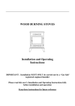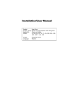
1
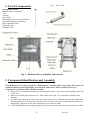
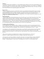
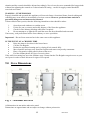
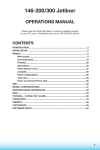
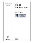
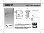
HOTHOUSE 8 FREESTANDING BOILER STOVE Please fix label with serial number and stove type here before putting manual into stove Installation and Operating Instructions Please hand these instructions to the stove user when the installation is complete. Leave the stove ready for operation and instruct the user in the correct use of the appliance and operation of controls. Important: – This product must be installed by a suitably qualified installer. Hothouse Inspired Products Ltd Imperial Point Express Trading Estate Stonehill road Farnworth Bolton BL4 9TN [email protected] PLEASE READ ALL THESE INSTRUCTIONS CAREFULLY! For safety reasons it is essential that your stove is correctly installed and operated. Hothouse cannot accept responsibility for any fault or consequential problems arising through incorrect installation or operation. TABLE OF CONTENTS Section Page No 1. List of Components 2. Component Identification and Assembly 3. Installation Instructions 2 2 3 Warnings and important safety information 3 4. Installation Information 4 Thermostat Chimney Ventilation Flue Draught Connection to Chimney Material Clearances Hearths 4 4 4 4 4 5 5 5. Boiler Connection 7 Plumbing Diagrams Link Up Injector Tee Pipe Thermostat Commissioning & Handover 7 9 9 9 9 6. Technical Data 7. Operating Instructions 10 10 Air controls Cleaning Fuels Notes on Wood Burning Lighting the stove Re-fuelling Shutting down Maintenance Seasonal Use 10 11 11 11 12 12 12 12 12 8. Safety Notes for your Guidance 9. Stove Dimensions 10. Frequently Asked Questions 11. Spares 1 11 12 13 14 HD01 09/11 Fig 1 – Stove Tool 1. List of Components Description of Parts Hothouse Stove Assembly Tool Ash Pan Flue Collar Flue Collar fixing screws & Washers Legs and fixing screws/washers Stove Operating Glove Touch up paint Warranty Card Qty 1 1 1 1 4 4 1 1 1 Fig 2 – Hothouse Stove Assembly and controls 2. Component Identification and Assembly Your Hothouse Stove comes packed in a cardboard box. Carefully remove any straps and remove all cardboard and any plastic packaging, open the door and remove all the contents. See List of Components section and check contents carefully. Remove the coal catcher by lifting it up and rotating it until it can be removed through the open door of the stove Remove the baffle plate from the stove. Please take note of fig. 2 for orientation of baffle when refitting. The flue collar can now be fitted to the top or back of the stove as desired using the M6 fixings and washers provided. Thread each nut onto the screw first, then put on the washer and place the screw through the fixing hole on the stove and finally screw onto the collar. Fit the blanking plate to the opening that is not to be used in same way as described above for collar. 2 HD01 09/11 3 Installation Instructions WARNINGS AND IMPORTANT SAFETY INFORMATION READ THESE INSTRUCTIONS CAREFULLY BEFORE INSTALLATION! These instructions cover the basic principles to ensure satisfactory installation of the stove, although detail may need slight modification to suit particular local site conditions. In all cases the installation must comply with current local regulations including Building Regulations, Local Authority Byelaws and other specifications or regulations including Ireland, UK or EU standards referred to as they affect the installation of the stove. Approved Document J is particularly important for England and Wales and can be downloaded for no cost at: http://www.planningportal.gov.uk/england/professionals/en/4000000000503.html Also of importance are Approved documents L1 A and B conservation of fuel and power. The Domestic Heating Compliance Guide will also be found useful. Important Chimney Warning This stove must not be installed into a chimney that serves any other heating appliance. Extractor Fan Warning There must not be an extractor fan fitted in the same room as the stove as this can cause the stove to emit fumes into the room. Cleaning and Chimney Sweeping The appliance, flue & chimney must be cleaned and checked internally and externally regularly in use and especially after a period on disuse (e.g. after summer). Lift down the baffle at least weekly to check for build up of soot or debris on the top from the flue pipe. Remove the baffle and check the flue spigot and connector is fully clear at regular intervals. The chimney and flue connector must be swept at least annually, more often when used with sooty fuels or damp wood. Any loose, broken or leaking joints or flue ways MUST be repaired immediately. Fuels Only use recommended fuels. The appliance can be damaged by burning petroleum coke, liquid fuels or general rubbish and this will invalidate your warranty and risk your personal safety. The appliance must not be used as a rubbish incinerator. Maintenance Annual checking and servicing of the appliance and flue by a competent engineer is recommended. Ventilation Adequate ventilation is ESSENTIAL for the safe and efficient operation of any solid fuel or wood burning appliance. Ventilation MUST be provided where required by the stove output or flue under-performance. Keep all ventilation clear and free of blockage. Health And Safety Precautions Handling Adequate facilities must be available for unloading and site handling. Hothouse Cassette Stoves are very heavily built so always ask for assistance when lifting and siting the stoves. Fire Cement Some types of fire cement are caustic and should not be allowed to come into contact with the skin. In case of skin contact, wash immediately with plenty of water. 3 HD01 09/11 Asbestos This stove contains no asbestos. If there is a possibility of disturbing any asbestos in the course of installation then please seek specialist guidance and use appropriate protective equipment. Metal Parts When installing or servicing this stove, proper care should be taken to avoid the possibility of personal injury. 4.0 Installation Information Thermostat We recommend that a thermostat control is fitted to your boiler which is used to automatically regulate the water output temperature and prevent water overheating in the boiler. The thermostat must be fitted as per the manufacturer‟s instructions which are included with the thermostat. Chimney The chimney height and the position of the chimney terminal should conform to Building Regulations. Minimum chimney height is 4.5m. Check that the chimney is in good condition, dry, free from cracks and obstructions. The diameter of the flue should not be less than 150mm and not more than 200mm. If any of these requirements are not met, the chimney should be lined by a suitable method. The chimney must be swept before connection to the stove. Where the chimney is believed to have previously served an open fire installation, it is possible that the higher flue gas temperature from the stove may loosen deposits that were previously firmly adhered, with the consequent risk of flue blockage. It is therefore recommended that the chimney be swept a second time within a month of regular use after installation. If you have any doubts about the suitability of your chimney, consult your local dealer/stockist or chimney specialist. If there is no existing chimney then either a solid fuel compatible prefabricated block chimney or a twin-walled insulated stainless steel flue to BS 4543 can be used. These chimneys must be fitted in accordance with the manufacturer‟s instructions and Building Regulations. Ventilation No purpose provided ventilation is required for stoves rated under 5KW. For each KW above 5KW, 550 sq mm of fixed ventilation is required – i.e. a stove rated at 8KW would require 3 x 550 sq mm = 1650 sq mm of fixed ventilation. If more than one appliance is installed in the same room, the ventilation requirements for each appliance must be added together. Flue Draught A flue draught of minimum 1.2mm to a maximum 2.5mm water gauge (12 to 25 Pascals) is required for satisfactory appliance performance. The flue draught should be checked under fire at high output and, if it exceeds the recommended maximum, a draught stabiliser must be fitted so that the rate of burning can be controlled to prevent over-firing. Connection to the Chimney This appliance is not suitable for use in a shared flue. This appliance requires a direct flue connection to the spigot. If practical, an existing fireplace opening can be bricked up or sealed with a register plate and a short length of flue pipe of a minimum 150mm internal diameter may then be used to connect the stove to the register plate in the chimney. This flue pipe should conform to Building Regulations. The stove must be insulated and properly fitted into the fireplace opening by back filling with 6:1 ratio vermiculite & cement mixture using minimal water through the top of the fireplace or flue spigot opening. The surface should be finished using 1:1:8 mix of cement, lime and sand. The connecting pipe is fitted with the spigot pushed up from inside the stove and rotated onto its keyhole slots to join to the pipe. Ensure that the pipe end is no closer than 76mm to the side or rear chimney walls. 4 HD01 09/11 If necessary a hole must be opened up into the flue way above the fireplace in order to fit the appliance to the flue correctly. Please consult HETAS recommended fitting methods if in doubt. It is essential that all connections between the stove and chimney-flue are sealed and made airtight with sealing rope, clamping rings and/or fire cement or heat resisting cement where required. Both the chimney and flue pipe must be accessible for cleaning and if ANY parts of the chimney cannot be reached through the stove (with baffle removed), a soot door must be fitted in a suitable position to enable this to be done. In adverse weather conditions, downdrafts may occur causing smoke or fumes to spill into the room. If this occurs the appliance should be shut down as much as possible by closing the air controls and the room should be ventilated to clear the fumes. If the problem persists seek the advice of a chimney sweep. Distances from NON-combustible materials: The stove can be recessed in a suitable sized non-combustible fireplace but a permanent free air gap of at least 50mm must be left around the sides and top of the stove to obtain reasonable heat output and for access to the stove for removal and maintenance. A clearance of 150mm will give a better heat output To conform with building regulations the fireplace recess walls should be at least 200mm thick or each rear leaf at least 100mm thick in the case of a cavity wall at the rear. If these dimensions are not met further protection for any combustible materials must be provided. The walls of the fireplace recess and the hearth must be made of non-combustible material. Hearths: Hothouse stoves require a 125mm thick non-combustible constructional hearth beneath them to protect the building, this can include any solid non-combustible floor. A non-combustible superimposed hearth forming an apron of at least 225mm at the front of the stove and 150mm on either side must also be provided. The superimposed hearth must not be less than 12mm thick and must have a clearly defined edge (change of level) to discourage placing of any combustible materials on or partially over it. The appliance shall be installed on a floor with adequate load-bearing capacity. If the existing construction does not meet this requirement, suitable measures (e.g. load distributing plate) should be provided to achieve it. 5 HD01 09/11 5.0 Boiler Connection 6 HD01 09/11 It is strongly recommended that this stove is fitted to your heating system by a knowledgeable, experienced and suitably qualified (Hetas or equivalent) plumber or Heating Engineer with experience in fitting boiler stoves. If fitted incorrectly it could result in serious damage to your home heating system. Plumbing should be carried out in accordance with Relevant Building Regulations and safe practices. The manufacturers cannot be held responsible for any losses due to incorrect specification or connection of the heating system. Gravity Circuit Do Not – Under any circumstances connect the stove to a sealed (pressurised) heating system or an unvented HW cylinder Do Not – Link the stove into a heating or hot water system with an existing boiler without the use of suitable equipment such as a neutralizer. When fitting this type of system the neutralizer manufacturer‟s instructions must be followed. Do – Fit an open cold feed and header expansion tank with separate cold feed and vent pipes. The cold feed and vent pipes must be unvalved. The open vent pipe should have a diameter of 22mm and rise continuously from the boiler. The gravity circuit should connect to a domestic indirect hot water cylinder of minimum 135lt capacity, using 28mm flow and return pipes, rising continuously from the boiler to the cylinder. Any nominally horizontal runs of gravity pipework should slope upwards at not less than 1:30. The base of the hot water cylinder should be located at least 150mm above the top of the stove. The gravity circuit must not contain any shut off valves and should be fully lagged to minimise heat loss. The pipes should not exceed 7.8 meters (25ft) in length to/from the cylinder. In general, the shorter the run of pipework the less heat loss and the more efficient the water heating. A heat soak radiator of at least 2kW must be used on the same gravity circuit, positioned above the stove. This is used to dissipate heat when the central heating is switched off or the HW cylinder is fully heated. 7 HD01 09/11 Link Up: On heating and hot water installations, a semi-pumped system should be used to the central heating system with gravity circulation to the hot water cylinder. For optimum performance of the boiler we recommend that all 4 tappings are used when using separate gravity and pumped heating loops. The flow and return pipes should be taken from diagonally opposite sides of boiler. Injector Tee: If only two tappings are used on a common flow system, they should be taken diagonally opposite and the remaining tappings should be plugged. An injector Tee should be fitted to join the gravity feed and central heating circuits back to the stove, which should be situated as close to the stove as possible. The tee connection encourages the stable flow of water through both circuits and prevents priority being given to the stronger flow, typically the pumped circuit. Pipe Thermostats A HIGH LIMIT thermostat should be fitted to the gravity flow pipe close to the boiler and set at 90°C.This should override any pump control, switching the pump on and dissipating any excess heat around the radiator circuit. To prevent boiler corrosion due to condensation it is necessary to maintain the return water temperature above 45°C. This can be achieved by the use of a LOWLIMIT thermostat on the return pipe from the hot water cylinder, close to the boiler. The thermostat should make on temperature rise, preventing the circulating pump from operating until the gravity circuit is up to temperature. Commissioning and Handover Upon completion of the installation, allow a suitable period of time for any fire cement and mortar to dry out. A small fire may then be lit and checked to ensure the smoke and fumes are taken from the stove up the chimney and emitted safely to atmosphere. Do not run the stove at full output for at least 3 – 4 days. On completion of the installation and commissioning, ensure that the operating instructions and operating tools for the stove are left with the customer. Ensure to advise the customer on the correct use of the appliance with the fuels likely to be used on the stove and warn them to use only the recommended fuels for the stove. Advise the user on what to do should smoke or fumes be emitted from the stove. The user should use a suitable fireguard in the presence of children, aged and/or infirm persons. All connections to the boiler should be checked to ensure there are no leaks during operation and that the flow and return water connections are working properly. The stove should be fired up initially by the Plumber / Heating Engineer to ensure that it is operating safely with the rest of the heating system. 8 HD01 09/11 6.0 Technical Data Hothouse 8B Technical Specifications (Wood) Total Heat Output kW 8.4 Output to Water kW 5.4 Output to Room kW 3.0 Efficiency % 77.7 CO Emission (@13% O2) % 0.38 Flue Gas Temp (avg. at nominal output) °C *270 Flue Gas Mass Flow g/s 7.2 Refuel Period hr 1.0 Inch 6” Product Weight (Packed) kg 144 Maximum Log Length mm 350 Safe Distance to Combustibles - sides mm **100 Safe Distance to Combustibles - back mm **200 Flue Outlet Size *Average reading at nominal output **In addition it is strongly recommended that any furniture or other combustible materials are kept at least 900mm clear from the front of the stove. 7.0 Operating Instructions This appliance is not designed for open operation and therefore should not be operated with the doors open. This stove is designed to burn cleanly with high efficiency. If used correctly this stove will burn with the very useful feature of clean glass. However, for this product to work properly it must be used correctly. It is essential that the stove has an adequate air supply for combustion and ventilation. The primary and secondary air inlets must be kept clear from obstruction. Warning! This appliance will be very hot when in operation and due care should be taken when operating the controls. A leather glove is provided to assist safe operation. Do not use an aerosol spray on or near the stove when it is alight. Air Controls Primary Air Primary air is controlled via the sliding air control at the bottom of the door. This provides a conventional air under draught to the bed of the fire. The primary air is used when lighting the stoves or when the fuel bed goes very low. The primary air inlet will usually be closed when burning wood and open when burning coal type fuel. 9 HD01 09/11 Secondary Air (Air Wash) Hothouse stoves are provided with a powerful “air wash” system. This secondary air supply to the stove is controlled via a sliding air control located on the top right of the stove, just above the door. If you want clean glass, always leave this control open some way whilst burning unless the stove is being shut right down for a long period. Moving the sliding control towards the wide side of the arrow increases the burn rate whilst moving it towards the narrow side reduces it. Multifuel Grate Your Hothouse Stove is fitted with a rotary style grate, which is operated from the front of the stove via a riddle rod. Use the “Hook” end of tool to operate the riddling system. This rotary grate is located in the centre of a cast iron flat bed with suitable air slots that assist the burning of most fuels. It is important to use the rotary grate to de-ash regularly, to ensure that the primary airflow is not impeded, as a build-up of ash can damage the cast iron bed. Ashpan It is essential that you empty the steel ash pan every day. Use the thick end of tool to hook onto and lift the ash pan out of the stove. DO NOT allow ash to build up underneath the bed as this may cause damage to the grate. Cleaning Glass: Despite the advanced air wash system provided, the glass will still need cleaning from time to time depending on the fuel quality and burning rates used. Never clean glass when the stove is hot. Always use stove glass cleaner or ceramic hob cleaner, which is available from your stove retailer. As an alternative, use a wet cloth with some of the wood ash if burning wood but be very careful to use very clean ash so as not to scratch the glass. Outer body: The outer body simply needs to be dusted from time to time. DO NOT use any kind of furniture polish or cleaning agent other than your stove suppliers recommended paint. Inner firebox: Brush the inside of the firebox clean from time to time to check the integrity of the plates and liners etc. It is not normally necessary to re-paint inside the firebox due to the high temperatures that mean that the paint does not have much effect before being burnt off. Steel and cast iron liners are resilient firebox materials and will give reliable service without major cleaning or work on the firebox. Baffle: It is essential to check the top of the baffle for build-up of soot and ash regularly when in use and after a long period of no use. From time to time remove the baffle if necessary to ensure that the flue way entrance is clear. Take note of the baffle orientation when removing and ensure it is refitted the same way. Fuels The appliance is fitted with a versatile multifuel grate, however the appliance has been tested and approved burning dry, well-seasoned logs. This is the recommended fuel. Notes on Wood burning Notes on Wood burning With a full load of wood, the stove will need to be refuelled approximately every 1.5 hours. Wood can be stacked higher in the stove than solid mineral fuel but care must be taken that logs do not touch the baffle. Wood burns most efficiently with the primary air controls closed and the secondary control partially open. Moving the secondary control will control the burn rate of the stove. Note – primary and secondary air is needed to light the stove, see section entitled „Lighting the Stove‟. Wood burns best on a bed of ash and it is therefore only necessary to remove surplus ash from the stove occasionally. Burn only dry, well-seasoned wood, which should have been cut, split and stacked for at least 12 months, with free air movement around the sides of the stack to enable it to dry out. Burning wet or unseasoned wood will create tar deposits in the stove and chimney and will not produce a satisfactory heat output. Do not use liquid fuels in this appliance. 10 HD01 09/11 Lighting the Stove We recommend that you have two or three small fires before you operate your stove to its maximum heat output. This is to allow the paint to cure in steadily and to give a long service life of the paint finish. During this curing in process you may notice an unpleasant smell whilst the finishes finally cure. It is non-toxic, but for your comfort we would suggest that during this period you leave all doors and windows open. First, open the primary and secondary air wash control fully. Load the firebox with plenty of starting fuel, i.e. paper, dry sticks and/or firelighters. Light the fire at the base leaving the primary and secondary air control fully open. Leave the door slightly ajar for 10 minutes to enhance initial starting and reduce smoke emission – DO NOT leave the stove unattended if the door is left ajar. Allow the fuel to reach a steady glow and build the fire up gradually by adding a few small sticks or well split logs at a time. Once you have a good fire bed established across the grate, further fuel can be added step by step as required. Don‟t be tempted to overload the fire bed with fuel all at once or close down the air controls too much until the fire is well established for some time. Once the ignition period is well under way close the primary air and gradually reduce the secondary air wash control opening to establish the burning intensity you require. Re-fuelling Refuelling It is best to refuel little and often, rather than in large pieces. When possible refuel the stove before the bed has gone too low. Open the secondary air control fully and add the fuel. Allow the fuel to burn for a few minutes until the fire is well established before closing the secondary air once again. This refuelling procedure will ensure that smoke emission is kept to a minimum. Shutting Down The stove will normally shut down by itself as the fuel is consumed. In order to shut down the stove for other reasons, close the primary air controls (if open), then close the secondary air control. If the controls are left in this position, the fire will eventually burn out. If you want to revive the fire open the secondary air controls fully. Warning! - The stove will remain very hot for a considerable time after the fire has died down or been extinguished. Warning!- Petroleum coke fuels or household waste must not be burnt on this appliance. Maintenance Inspect the inside of the firebox and above the baffle plate every week during use. See chimney cleaning section in section 3.1 Warnings and Important Information. Inspect the inside of the stove and the flue ways and ensure they are 100% clear after a period of disuse (e.g summer). Only use manufacturers recommended replacement parts on the appliance Seasonal Use Remove the baffle and inspect the inside of the stove and the flue ways and ensure they are 100% clear after a period of disuse, for example if the stove is not used during the warmer periods of the year. Also set the air controls to 50% to keep the appliance ventilated and stop the build-up of any moisture inside. 8.0 Safety Notes for your guidance FIRES CAN BE DANGEROUS – Always use a fireguard in the presence of children, the elderly or the infirm. DO NOT perform modifications to the appliance as this could seriously compromise safety in operation. DO NOT OVERFIRE – it is possible to fire the stove beyond its design capacity, this could damage the stove, so watch for signs of over firing – if any part of the stove starts to glow red, the fire is in an over fire 11 HD01 09/11 situation and the controls should be adjusted accordingly. Never leave the stove unattended for long periods without first adjusting the controls to a reduced and safe setting – careful air supply control should be exercised at all times. WARNING – FUME EMISSION Properly installed and operated, this appliance will not emit fumes. Occasional fumes from de-ashing and refuelling may occur which is not normally of serious concern. However, persistent fume emission is potentially dangerous and must not be tolerated. If fume emission does persist, then the following immediate action should be taken: 1. Open doors and windows to ventilate room 2. Let the fire out, or remove and safely dispose of fuel from the appliance. 3. Check for flue chimney blockage and clean if required. 4. Do not attempt to re-light the fire until the cause has been identified and corrected. If necessary, seek professional advice from chimney or stove specialists. Important! – Do not fit an extractor fan in the same room as this appliance. IN THE EVENT OF A CHIMNEY FIRE Raise the alarm to let others in the house know. Call the Fire Brigade Reduce the appliance-burning rate by closing all air controls fully. Move furniture and rugs away from the fireplace and remove any nearby ornaments. Place a fireguard or spark guard in front of the stove. Feel the chimneybreast for sign of excessive heat. If the wall is becoming hot, move the furniture away. Ensure that the Fire Brigade can gain access to your roof space in order to check this area for signs of fire spread. 9.0 Stove Dimensions Fig. 3 – Hothouse 8B Stove All dimensions in mm unless otherwise stated. Dimensions are approximate and are subject to change without prior notice. 12 HD01 09/11 10.0 Frequently Asked Questions 1 Do stoves require a chimney? All of our multi fuel and wood burning stoves require a suitable chimney or professionally installed flue system. 2 How do I clean the chimney? You will require a chimney sweep to clean the chimney. It is essential to provide a dedicated chimney cleaning access door when installing the flue of the stove in some situations. In other situations the chimney can be swept through the firebox. 3 Who should install my stove? Hothouse Stoves want you to enjoy the maximum performance from your appliance. To ensure this, it is essential that they are installed correctly. We strongly recommend that your stove is installed by a suitably qualified installer e.g HETAS. 4 How do I regulate the heat output? Each stove has various air controls, which will allow you to easily regulate the heat output and refuelling rate. 5 What warranty do I get? Hothouse Stoves will replace, free of charge, any working part that fails (under normal operating conditions) within 12 months of purchase. Consumables such as glass, firebox lining boards or stove rope and adhesives are not guaranteed. A call out charge will apply if our engineer attends any stove problem that is not related to product failure. 6 Where can I get spare parts? Your local Hothouse Stove retailer will be pleased to supply spare parts and to provide any other information you require. 7 Can the doors be left open while burning? For safety and heat efficiency the doors should remain closed. 8 Why is the stove smoking when lit? A flue with back draught problems is almost certainly the cause of a smoking stove. Also check adequate ventilation is present. A qualified fitter should complete both a smoke pressure and flow test prior to fitting the stove to ascertain the integrity of the flue. 9 Why should I “Run in” my stove? To begin, light a series of small fires over a period of a few days to allow the paint finish to cure. The stove is finished with a highly heat resistant paint. The finish can be renovated with stove paint available from your local stove retailer. If the stove is not “run in” correctly, this may cause the paint to discolour and flake. 10 What is Over Firing? Your stove should never be used in a manner to cause over firing. Over firing can be caused by over loading the stove with fuel, and with primary controls open. If any part of stove glows "red" your stove is over firing and your draught control should be adjusted to restrict airflow to stove. Over firing can cause permanent damage to the appliance, which is not covered by warranty. 13 HD01 09/11 Spare Parts List and Codes HD01 09/11 14 Hothouse Inspired Products Ltd Imperial Point Express Trading Estate Stonehill road Farnworth Bolton BL4 9TN Tel: 01204 - 862286 15 Fax: 01204 - 868569 HD01 09/11