1
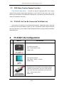
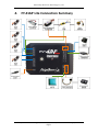
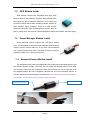
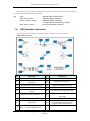
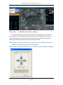
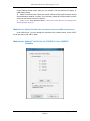
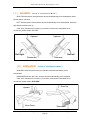
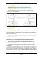
FY-41AP Lite AutoPilot & OSD System Installation & Operation Manual Guilin Feiyu Electronic Technology Co., Ltd Addr : 4th Floor,YuTaiJie Science Technology Building,Information Industry Park , ChaoYang Road ,Qi Xing District ,Gui Lin ,541004 Website: www.feiyu-tech.com Email: [email protected] Guilin Feiyu Electronic Technology Co., Ltd. Table Of Content User Agreement ................................................................................................................................ 1 1. FY-41AP Lite AutoPilot System Introduction ................................................................................. 2 2. Function Introduction ................................................................................................................ 3 2.1 FY-41AP Lite Single Module Function (Don’t connect the GPS module)............................ 3 2.2 FY-41AP Lite With GPS Function ........................................................................................ 4 2.3 OSD Video Overlay System Function .................................................................................. 5 2.4 FY-41AP Lite Can Be Connected To A Data Link.................................................................. 5 3. FY-41AP Lite Configuration ......................................................................................................... 5 4. FY-41AP Lite Connection Summary ............................................................................................ 7 5. S1~S8 Servo Interface Connection Instructions ......................................................................... 8 6. Connection Introduction ............................................................................................................ 8 7. Main Module Installation ......................................................................................................... 10 7.1 FY-41AP Lite Module Installation ..................................................................................... 10 7.2 GPS Module Install ........................................................................................................... 11 7.3 Power Manager Module Install ........................................................................................ 11 7.4 Airspeed Sensor Module Install ....................................................................................... 11 7.5 Remote Control Setting: SW1&SW2 ................................................................................ 12 7.6 Gyroscope Reset............................................................................................................... 12 7.7 FY-41AP Lite Indicator Light Instruction ........................................................................... 13 7.8. OSD Interface Instruction ................................................................................................ 14 8. FY-41AP Lite Setting ................................................................................................................. 15 9. FY-41AP Lite First Flight Test Checklist ........................................................................................ 28 10. Other Functions And Settings ................................................................................................ 30 10.1 Switch ( SW2 ) Function Setting .................................................................................. 30 10.2 RC Max Distance Setting.............................................................................................. 30 10.3 Circling Radius Setting ................................................................................................. 31 10.4 The Altitude Of Return To Launch Instructions ........................................................... 31 10.5 FAIL-SAFE Setting ......................................................................................................... 32 10.6 Fixed Altitude & Heading Lock Mode Instruction ....................................................... 32 10.7 3D Mode Instruction ................................................................................................... 33 10.8 Auto Circling Mode Instruction ................................................................................... 33 10.9 Link Mode (RC Receiver Control Mode/Data Radio Control Mode) ............................ 33 Guilin Feiyu Electronic Technology Co., Ltd http://www.feiyu-tech.com [email protected] Guilin Feiyu Electronic Technology Co., Ltd. Dear Customer : Thank you for choosing FY-41AP Lite as your autopilot system. Please read this manual carefully to ensure correct installation & operation. User Agreement The use of FY-41AP Lite is prohibited for any illegal intentions and purposes. The user will be fully responsible for the use of this product and FY-Tech will not be held liable it's misuse either in its original or altered state by the customer (including the direct, indirect, or third party losses caused by a faulty plane or plane crash). Please read this manual carefully before using this product. If you have any questions, do freely contact us and we will attempt to provide you with a satisfactory clarification and/or resolution should it be required. The products‘ functions maybe changed only by firmware upgrades which is available from our website from time-to-time. Please do check our website for available firmware upgrades. The company reserves the right to alter the contents of the product firmware. This agreement takes immediate effect upon the purchase of the product. Attention The installation and use of this device require some skill and knowledge in flying remote controlled aircraft. If you are a complete beginner & have never flown one before, we do not recommend you install this device on your own. Please find an experienced RC pilot who may provide you with the basic knowledge required to use this device successfully. If you are already an experienced flyer, you will find the FY-41AP Lite installation to be easy & logical. Follow this manual & you won‘t go wrong. If you need further technical support, contact us at: [email protected] Guilin Feiyu Electronic Technology Co., Ltd http://www.feiyu-tech.com Page 1 [email protected] Guilin Feiyu Electronic Technology Co., Ltd. 1. FY-41AP Lite AutoPilot System Introduction FY-41AP Lite Module FY-41AP Lite is an inertial attitude measurement instrument used for FPV flight on fixed-wing aircrafts. It has an integrated OSD video overlay system that presents critical flight information such as power management, airspeed, altitude, and flight direction via its electronic compass, allowing for a clear visual flight while ensuring key information is within sight. The new FY-41AP Lite with its enhanced altitude control and GPS module, can now realize improved pinpoint inertial navigation and automatic piloting. Flight stabilization is achieved via an integrated 3 axis gyro, 3 axis accelerometer, and a barometric pressure sensor. This enables the module to accurately measure flight attitude, earth azimuth & relative altitude to achieve: Extremely stable conventional flight pattern Stabilized 3D flight Automatically return to home (RTL) Fixed altitude flight Heading lock flight Auto circling over a fixed GPS location. GPS Module GPS module enables the FY-41AP Lite to calculate the flight course & sense the exact location of the aircraft. GPS data allows aircraft return to home (RTL), auto circle, and control straight line navigation. Airspeed Module The FY-41AP Lite can be connect to the airspeed sensor (When don‘t connect the airspeed sensor, the FY-41AP Lite also can work normally).The airspeed sensor can measure the airspeed of the aircraft. Compared to the GPS speed the airspeed have the characteristics which is small delay and small affected by the wind. This characteristics can achieve the effective control of the throttle, improve the efficiency of flight and flight safety OSD System FY-41AP Lite has integrated OSD hardware with optimizing display interface. Critical flight parameters are displayed like altitude, speed, direction, flying voltage and amp draw, and most display parameter outlay can be changed via RC control. Guilin Feiyu Electronic Technology Co., Ltd http://www.feiyu-tech.com Page 2 [email protected] Guilin Feiyu Electronic Technology Co., Ltd. Power Manager Module FY-41AP Lite can connect power manager module which is integrated with current sensor module and Voltage-Regulating module. Current Sensor is used to check voltage, Amp draw. The integrated Voltage-Regulating module provides stable +12V to FPV video camera and video transmitter. Altitude Control Altitude control is achieved using a high sensitivity barometric sensor which measures relative height. Altitude is fixed via elevator servo control and throttle management. Heading Control Under the condition of without GPS module, heading control is achieved by the inertial device. Both the aileron & rudder servo is used to control flight heading. But it will t influence of wind deviation from the original route. Under the condition of connect to the GPS module, GPS data is used to automatically correct heading even in windy conditions. Speed Control Under the condition of without airspeed sensor but connect to the GPS module, GPS module provide the speed and altitude information for the throttle control to achieve the control of the speed. When connect to the airspeed sensor, the airspeed information will available and use for controlling the throttle, and the speed control is more reliable and accurate. 2. Function Introduction 2.1 FY-41AP Lite Single Module Function Note: Don’t connect the GPS module ● Activated Mode In this mode, the FY-41AP Lite auto stabilization is turned off. The aircraft is completely under pilot control. ● Stabilized Mode Level flight is automatically maintained, making flight simple, especially for beginners. If a pilot feels the plane is out of control, simply reduce input control and the plane will automatically recover level flight. Guilin Feiyu Electronic Technology Co., Ltd http://www.feiyu-tech.com Page 3 [email protected] Guilin Feiyu Electronic Technology Co., Ltd. ● 3D Mode If no input is given by the pilot (all sticks in the middle position), 3D mode will lock the current aircraft attitude. Therefore the aircraft can be easily maneuvered to complete a variety of 3D flight with added stability & smoothness. ● Fixed altitude & Heading lock Mode This mode maintains aircraft flight course & holds the altitude on activation.The system automatically corrects flight course deviation & maintains straight-line flight. ● Auto Circling Mode On activation, the plane will maintain altitude and flight speed, while initiating a counterclockwise circle, but this is not hovering around a fixed point, is likely to be blown away from the original place of circle. 2.2 FY-41AP Lite With GPS Function ● Fixed altitude & Heading lock Mode This mode maintains aircraft flight course & holds the altitude on activation. By using GPS data, the system automatically corrects flight course deviation & maintains straight-line flight. ● Auto Return To Launch Mode (RTL) Upon activation of this Mode, the aircraft will automatically return to the Home point, maintaining is current altitude. Upon reaching the Home point, it will initiate auto circling. After the aircraft back to the target point ,if the altitude greater than 100 meters , the aircraft will down to 100 meters while circling. For the FY-41AP Lite , there is 50 meters protection altitude for return home .If the altitude below 50 meters when activate into RTL, the aircraft will climb to 50 meters while return. ● Auto Circling Mode On activation, the plane will maintain altitude and flight speed, while initiating a clockwise circle. The centre of the circle is the point of activation at a default radius of 80 meters (can be changed via FY GCS). ● GCS software By using a field computer and connecting the FY41AP Lite to an FY Data Radio via the UART port, you can set the FY41AP Lite flight parameters, monitor the flight progress & record / reply the flight via the FYGCS software. For more information, please refer to the FY Data Radio manual. NOTE: 1 ) In the navigation mode, the remote control lever (AIL ,ELE,THR,RUD) no longer can control the aircraft except Fixed altitude & Heading lock Mode. 2 ) In Fixed altitude & Heading lock Mode, operation the throttle lever is invalid, in this mode operation AIL,ELE,RUD lever are effective. 3) In the navigation mode, when the flight altitude below a certain altitude, the flight speed below a certain speed, the throttle will automatically shut down. Guilin Feiyu Electronic Technology Co., Ltd http://www.feiyu-tech.com Page 4 [email protected] Guilin Feiyu Electronic Technology Co., Ltd. 2.3 OSD Video Overlay System Function First Person View (FPV) FY-41AP Lite has an integrated OSD video overlay system that presents critical flight information on the video for easy enjoy FPV, at the same time, Auto stable, Fixed altitude & Heading lock,, Auto Return To Home function will make FPV operation more easy. 2.4 FY-41AP Lite Can Be Connected To A Data Link Connecting to a Data Link can increase flight distance. Additionally, when used with FY-GCS (Ground Control Station) system you can view telemetry data of flight conditions and more effectively, you are able to make changes real-time including change parameter, flight attitude etc 3. NO . FY-41AP Lite Configuration Module Introduction FY-41AP Lite module 1 Size: 61mm*39mm*14mm Weight: 20g GPS receiver module 2 Size: 32mm * 32mm * 13.5mm Weight: 24g Integrated with Current Sensor and regulate voltage module to provide stable +12V to FY-41AP Lite and 3 FPV video camera and transmitter at the same time. Size: 50mm*24mm*18mm Weight: 35g Guilin Feiyu Electronic Technology Co., Ltd http://www.feiyu-tech.com Page 5 [email protected] Guilin Feiyu Electronic Technology Co., Ltd. To measure airspeed 4 Size: 64.5mm * 13.5mm * 13.5mm Weight: 9g For FY-41AP Lite firmware upgrade 5 For connect data link to PC For connect remote adapter to PC 6 For connect FY-41AP Lite to remote receiver 7 For connect video camera or video transmitter 8 Can weld to power manager module for connect the batter and ESC 9 GPS extension wire Guilin Feiyu Electronic Technology Co., Ltd http://www.feiyu-tech.com Page 6 [email protected] Guilin Feiyu Electronic Technology Co., Ltd. 4. FY-41AP Lite Connection Summary Z Guilin Feiyu Electronic Technology Co., Ltd http://www.feiyu-tech.com Page 7 [email protected] Guilin Feiyu Electronic Technology Co., Ltd. 5. S1~S8 Servo Interface Connection Instructions No. Type Traditional S Aileron servo 1 S2 Elevator servo S3 Flying wing V tail Airship Aileron &Elevator mix control servo 1 Aileron &Elevator mix control servo 2 Aileron servo 1 Not use Elevator &Rudder mix control servo 1 Elevator servo Throttle servo/ESC Throttle servo/ESC Throttle servo/ESC Throttle servo/ESC S4 Rudder servo Not use S5 Aileron servo 2 Not use Elevator &Rudder mix control servo 1 Aileron servo 2 S6 Not use Not use Not use Not use S7 Not use Not use Not use Not use S8 Not use Not use Not use Not use Rudder Servo Not use NOTE: When using remote adapter, S7 and S8 output the channel 7 and channel 8 signal of the RC receiver directly. 6. Connection Introduction Connection Picture Introduction S1~S8 servo wiring connection Pay attention to the signal wiring sequence Power manager wiring GPS module wiring Guilin Feiyu Electronic Technology Co., Ltd http://www.feiyu-tech.com Page 8 [email protected] Guilin Feiyu Electronic Technology Co., Ltd. 2×4P RC receiver wiring For FY-41AP Lite Black Red White —— AIL Orange —— ELE Green —— THR Yellow —— RUD Brown —— CH5 Blue —— CH6 Airspeed meter wiring Video camera wiring Yellow-video signal Red--+12V Black--GND Video transmitter wiring Yellow-video signal Red--+12V Black--GND Connect the USB data cable to UART1 port to firmware upgrade for FY-41AP Lite control module Connect the USB data cable to UART2 port to firmware upgrade for OSD module Data link wire Connect the FY-602 data radio to UART1 port Vibration absorbing pads (dampers),use for FY-41AP Lite vibration damping installation. Guilin Feiyu Electronic Technology Co., Ltd http://www.feiyu-tech.com Page 9 [email protected] Guilin Feiyu Electronic Technology Co., Ltd. 7. Main Module Installation 7.1 FY-41AP Lite Module Installation When installing, please keep FY-41AP Lite horizontal and as close as possible to the "Centre of gravity" (COG) of the aircraft. The modules orientation can be changed by FY-GCS (Ground Control Station) system: arrow to front, back, left or right. Efficient anti-vibration components are very important and to be used when installing. You can use the included ‗vibration absorbing dampers‘ or your DIY equipment. Please note: For Nitro planes, flying without using efficient ‗anti vibration dampers‘, will lead to FY-41AP Lite working abnormally. Arrow forward(Default direction) Nose of the plane araaa Arrow towards to right Arrow towards to left Arrow towards to back Guilin Feiyu Electronic Technology Co., Ltd http://www.feiyu-tech.com Page 10 [email protected] Guilin Feiyu Electronic Technology Co., Ltd. 7.2 GPS Module Install GPS receiver module has integrated plate type GPS passive antenna with stronger reception ability shielding the false signal by ground reflection efficiently. Don‘t install next to metal or carbon fiber & other shielding material, which may block satellite signal reception. Install the GPS module horizontal and away from electromagnetic sources such as ESC‘s, power wires, servo wires & video transmitters which can interfere with GPS signal. 7.3 Power Manager Module Install Power manager module supports 2S~6S lithium battery input. The integrated current sensor can measure APM draw and voltage; DC-DC module offers 5V to FY-41AP Lite meanwhile 12V to video camera and video transmitter. But servo power is supplied by ESC or S1~S8 any port access. 7.4 Airspeed Sensor Module Install The airspeed sensor need to pull ahead the front of the pneumatic opening and in the line with the direction of flight, cannot tilt. You can install the Airspeed sensor to the wing or in the front of the nose, do not block the front of the air inlet, we can use the glue to fix the airspeed sensor. But can't completely obturate the end of the airspeed sensor, to maintain pressure connected with the outside world. Note: Make sure that after installation, the fuselage in flight airflow can not interfere with air intakes. Static Pressure Port Dynamic Pressure Port Guilin Feiyu Electronic Technology Co., Ltd http://www.feiyu-tech.com Page 11 [email protected] Guilin Feiyu Electronic Technology Co., Ltd. 7.5 Remote Control Setting: SW1&SW2 FY-41AP Lite needs remote control and receiver with at least 6 channels, including 4 normal channels for AIL,ELE,THR,RUD, and two for SW1,SW2 to control flying mode. You need to choose normal fixed wing plane mode canceling all mix control modes, meanwhile setting CH5,CH6 to two three-switch. FY-41AP Lite need two three-switch to control flying mode:SW1 for deactivated mode, stable mode, 3D mode; SW2 for return to home and fixed attitude and head locking mode (default mode),or circle mode(need reset). After setting the Switch, you can double check by monitoring the indicator light on the module against selected flying mode. Detail please see the ―FY-41AP Lite indicator light instruction‖. SW1&SW2 default set: SW1 SW2 Deactivated RTL Stable NULL 3D ADH NOTE: SW-2 has priority over SW-1. Only when SW-2 is in the ‗Null‘ Mode can SW-1 work. Therefore ‗Null‘ should be one of the options for SW-2, otherwise SW-1 will not work. 7.6 Gyroscope Reset If the following conditions occur, the FY-41AP Lite initialization is recommended: 1. The device has not been used for a long time. 2. There is a change in environmental temperature of over 30 degrees since last flight. 3. The purple LED flashes continuously even when the FY-41AP Lite remains stationary and you never activate the motor.(When in the non navigation mode, which means SW2 is on the position ―NULL‖). Note: For the better flight, we suggest that to do the gyro reset before each flight. There are three way to realize the gyro reset. (The FY-41AP Lite must keep stationary during the gyro reset procedure) Guilin Feiyu Electronic Technology Co., Ltd http://www.feiyu-tech.com Page 12 [email protected] Guilin Feiyu Electronic Technology Co., Ltd. (1) Through SW1: On SW1, switch ABM to Deactivated Mode 6 times, time interval has to be less than 3 seconds as follows: ABM→ Deactivated Mode → ABM → Deactivated Mode → ABM → Deactivated Mode → ABM → Deactivated Mode → ABM → Deactivated Mode → ABM → Deactivated Mode. After doing this operation, the LED will bright white light about 1S.Wait for the LED go out, then the gyro initialization finish. (2) Through OSD video overlay menu ―INIT GYRO‖ option. (3) Through the ― FYGCS 5.11 for 41& DOS ‖setting software ―Initialize the gyro‖ button which in the ―Autopilot Configuration Wizard‖ option. (Note: Making gyro initialization via the OSD menu and the ―FYGCS 5.11 for 41&DOS ‖ setting software, won't appear the phenomenon of the LED bright white light.) 7.7 FY-41AP Lite Indicator Light Instruction FY-41AP Lite with three colors LED which can send out red, blue, green light. Also yellow, white, purple and other colors light through the combination. Operators can know the FY-41AP Lite‘s operating mode by judging the different colors which the LED sends out and the flash frequency. Green light flash means GPS location fixed, red and blue light indicate FY-41AP Lite working mode. Guilin Feiyu Electronic Technology Co., Ltd http://www.feiyu-tech.com Page 13 [email protected] Guilin Feiyu Electronic Technology Co., Ltd. Note: When the FY-41AP Lite needs Gyro Reset or FY-41AP Lite module is in a state of motion, the LED will bright purple light. e.g. Red Manual Mode, GPS not lock Red—Red—Green Stabilized Mode, GPS lock Purple—Purple—Green Stabilized Mode, GPS lock, If it stay static means need Gyro Reset. Blue—Blue—Green Auto Circling Mode, GPS lock 7.8. OSD Interface Instruction The integrated OSD module supports PAL or NTSC form video input. OSD display interface: No. Instruction No. Instruction 1 GPS altitude(Unit: m) 10 Relative altitude (Unit: m) 2 The quantity of satellite used for positioning 11 GPS speed (Unit: km/h) 3 Airspeed/GPS speed (Unit: km/h) 12 Flight total mileage (Unit: km) 4 The battery voltage (Unit: V) Battery power consumed (Unit: mA/h) 13 Total flight time (Format:h:m:s) 14 Current course of flight (Unit: deg) 6 Distance to Home Point (Unit: m) 15 The angle of turning to the Home Point (Unit: deg) 7 Power battery current (Unit: A) 16 8 Flight mode 17 9 Current latitude & longitude of the plane (Format: dddmm.mmm) 5 Guilin Feiyu Electronic Technology Co., Ltd Attitude table Relative position of Home Point (Icon in the middle position when the aircraft is around Home Point.) http://www.feiyu-tech.com Page 14 [email protected] Guilin Feiyu Electronic Technology Co., Ltd. Flight mode instruction 8. Name Introduction Name Introduction RC Deactivated mode RTL Return to home 3D 3DAerobatic Flight ADH ABM Stable mode ACM Fixed altitude & Heading lock Mode Circle mode FY-41AP Lite Setting There are two ways to set the FY-41AP Lite, one is via remote control and OSD overlay menu settings. Another solution is connected via USB cable to the computer by using the setting software to set up. Here we introduce the use of these two methods. Method one: menu Setting FY-41AP Lite via remote control and OSD overlay 1 ) Activate the OSD setup menu: switch "ABM" to the "3D mode" 6 times in SW1, between two switching it has to be less than 3 seconds, the process is as follows: ABM → 3D mode →ABM →3D mode → ABM → 3D mode → ABM → 3D mode →ABM → 3D mode →ABM→ 3D mode→ABM. This will activate OSD setup menu interface. 2 ) Move Elevator stick to the project you want to set. 3 ) Move aileron stick to the project you want to set. 4 ) Please put elevator stick to SAVE, after your setting. Through the stick of ailerons carried out to save the action, when saving, "SAVE" will flicker for two seconds, the end of the flashing, been saved successfully. Guilin Feiyu Electronic Technology Co., Ltd http://www.feiyu-tech.com Page 15 [email protected] Guilin Feiyu Electronic Technology Co., Ltd. Setup instructions NO. Setup instructions NO. 1 Auto-control rudder surface reverse 10 Circling radius setting 2 Control gain 11 Farthest flight distance setting 3 Ailerons 12 Airspeed adjust setting 4 Elevator 13 Rudder mixing mode 5 Rudder 14 Initialize gyroscope 6 Throttle 15 Initialize airspeed sensor 7 Three-switch mode selection 16 Save the settings 8 FY-41AP Lite install setting 17 Exit the Settings interface 9 Cruising speed setting Method two: software Setting FY-41AP Lite via “FYGCS 5.11 for 41&DOS” 1 ) Please visit the official website: www.feiyu-tech.com. Download the newest setting software ―FYGCS 5.11 for 41&DOS‖ and the USB driver at the download page which related to FY–41AP Lite products. 2 ) After successfully install the USB driver, insert the USB-TTL interface cable into computer USB COM port(don‘t connect TTL port to any other device ) , the system will correctly identify the USB -TTL data cable, then you will find there is more than one port(COM and LPT), the port COM6 in the ―Silicon Labs CP210x USB to UART Bridge (COM6)‖ is the Virtual serial number. Inserter a few times for confirmation the virtual serial number. After that, you can use the new USB data cable normally. 3 ) Install Google Earth plug-in 6.1 version or above. Two methods to install the plug-in . Method one: Networking installed directly. Method two: Install the local plug-in provided by us, you can download at our official website: www.feiyu-tech.com. Method for checking whether the Google Earth plug-in have been installed successfully. Enter the following url : http://www.google.com/earth/explore/products/plugin.html . If the plug-in have been installed successfully, you can see the following 3D map directly. Guilin Feiyu Electronic Technology Co., Ltd http://www.feiyu-tech.com Page 16 [email protected] Guilin Feiyu Electronic Technology Co., Ltd. 4 ) Install the software ―FYGCS 5.11 for 41&DOS‖. The software in addition to can use for setting up and configuring FY-41AP Lite also included other functions. For example, Electronic mapping, Telemetry data monitoring of flight parameters, Flight attitude, Flight speed, Altimeter, Location, Recording and Playback of telemetry data into Ground Control Station, Map loading ,etc . The FYGCS5.11 software include Google earth live map, also can support 2D view and 3D view at the same time. Support in offline mode display the map which have been browse. a) Double-click ― ‖ installed by default. b) After installation, double-click ― ‖ to open the FYGCS5.11 software, you can see the following interface. Guilin Feiyu Electronic Technology Co., Ltd http://www.feiyu-tech.com Page 17 [email protected] Guilin Feiyu Electronic Technology Co., Ltd. c) Confirmation has been connected to the network, click the ―3D‖button ,you can switch to the Google earth map. Note: If you can’t open FYGCS5.11 successfully in Vista, Win7, or Win8 operating system . Please find out executable file, right click the mouse and run as administrator. Please according to the picture below, through USB data cable to connect FY-41AP Lite to PC. Connect FY-41AP Lite to your PC, select corresponding COM port. Baud rate has to be―19200‖, click ―connect‖ button. After FY-41AP Lite establish connection with the GCS software successfully .Select the ―Menu-> Autopilot Configuration Wizard‖ ,you can finish the setting in the configuration wizard. The last,you can click the button ― ‖ to save the setting into the FY-41AP Lite controller. Guilin Feiyu Electronic Technology Co., Ltd http://www.feiyu-tech.com Page 18 [email protected] Guilin Feiyu Electronic Technology Co., Ltd. Step One: Installation direction setting First you should set the correct mounting direction according to the FY-41AP Lite mounting direction on the plane(The default setting is Arrow forward).After choose the correct mounting direction, pitch and roll inclined the plane and checking through the attitude chart whether the posture and aircraft state is identical. Method one: Setting FY-41AP Lite via remote control and OSD overlay menu Setting via the "Install Setting" option in the OSD menu. Method two: Setting FY-41AP Lite via “FYGCS 5.11 for 41&DOS” software Guilin Feiyu Electronic Technology Co., Ltd http://www.feiyu-tech.com Page 19 [email protected] Guilin Feiyu Electronic Technology Co., Ltd. Servo’s output mix control mode setting Step Two: No. Option Normal Elevon V-Tail Normal “AIL NAV‖means using only aileron make a turn in navigation mode. ‖RUD NAV‖means using only rudder make a turn in navigation mode. Method one: Setting FY-41AP Lite via remote control and OSD overlay menu Select the correct rudder output based on the aircraft model. Setting via the ―MIX SETTING‖ option in the OSD menu. Aircraft Config Mix Setting Selection Remark Traditional aircraft layout with Aileron 1.Normal Navigation control using aileron. 4.Normal(RUD NAV) Navigation control using rudder. 2.Elevons Navigation control using aileron. Used for most kinds of flying wing planes. 5.Elevons(RUD NAV) Used for flying wings with independent rudder for Navigation. 3.V-Tail V-Tail with navigation via aileron. 6.V-Tail(RUD NAV) V-tail planes with independent Rudder for navigation control. 1. Normal The rudder servo must be connected to FY-41AP Lite aileron servo output (AIL) Flying wing aircraft V-Tail aircraft with Aileron Traditional aircraft layout with no Aileron V-tail without aileron Airship 2. Elevons 4.Normal (RUD NAV) Guilin Feiyu Electronic Technology Co., Ltd V-tail servo has to connect to FY41AP Lite Differential Servo 1 & 2 output. Due different airship configurations, use with caution. Carry out test flights to confirm normal function. http://www.feiyu-tech.com Page 20 [email protected] Guilin Feiyu Electronic Technology Co., Ltd. Method two: Setting FY-41AP Lite via “FYGCS 5.11 for 41&DOS” software Step Three: The remote control switch setting & checking and setting the direction of the rudder surface automatically control . FY-41AP Lite requires a minimum of 6-channel RC receiver. 1) First, the remote control is set to fixed-wing aircraft of conventional layout mode, do not set any mixing. The rudder angle of the remote control is set to 100%, and fine-tune gyrus. 2) Need two three-position switch or rotary switch settings for CH5, CH6 used to connect SW1 and SW2. Use for switch the flight mode. 3) Connection is completed, switch CH5, CH6 to check the settings whether can Guilin Feiyu Electronic Technology Co., Ltd http://www.feiyu-tech.com Page 21 [email protected] Guilin Feiyu Electronic Technology Co., Ltd. correct setting control mode. Also you can confirm it via the status of the lights, or OSD display mode. 4) Switch to manual mode, check the control surfaces of the joystick remote control aircraft direction whether is correct, if not correctly, adjust the rudder surface reverse control on the remote control to correct it. 5) Switch to the "Auto Balance Mode", check the control direction according to the following steps carefully. Method one: Setting FY-41AP Lite via remote control and OSD overlay menu In the OSD menu, you can change the direction of the rudder control via the ―REV‖ list of the ―Servo Gain REV‖ option. Method two: Setting FY-41AP Lite via “FYGCS 5.11 for 41&DOS” Software Guilin Feiyu Electronic Technology Co., Ltd http://www.feiyu-tech.com Page 22 [email protected] Guilin Feiyu Electronic Technology Co., Ltd. (1) AILERON (Check in "Auto Balance Mode" ) RIGHT Roll the plane, the right aileron should automatically move downwards, while the left aileron move up. LEFT Roll the plane, the left aileron should automatically move downwards, while the right aileron should move up. If the servo movement is incorrect, you need to reverse the automated servo movement, please select ―AIL REV‖. Upward Upward Roll right Roll left Downward Downwar d (2) ELEVATOR (Check in "Auto Balance Mode" ) UPWARD incline the plane nose, the elevator should automatically move downwards. DOWNWARD incline the nose, elevator should automatically move upwards. If the servo movement is incorrect, you need to reverse the automated servo movement, please select “ELE REV”. Nose Up Upward Nose Down Guilin Feiyu Electronic Technology Co., Ltd Downward http://www.feiyu-tech.com Page 23 [email protected] Guilin Feiyu Electronic Technology Co., Ltd. (3) Rudder (Check in "Auto Balance Mode" ) CLOCKWISE rotate your plane, the rudder should move to the Left. COUNTERCLOCKWISE rotation, the rudder should move to the Right If the servo movement is incorrect, you need to reverse the automated servo movement, please select “RUD REV”. Turn right Turn left Rudder moves to the left Rudder moves to the right ( 4 ) Throttle Push throttle from light to strong, if the servo display chart of the remote control is display (-100 to 100) please don‘t select the‖ throttle reverse‖ option in the rudder reverse, if display chart display from big to small (100 to -100), please select the‖ throttle reverse‖ option in the rudder reverse. In general, use ESC for throttle controlling can be choose the default settings (NOR), without ESC reverse setting. Step Four: Basic sensitivity setting for automatic control We suggest that the first flight should be in default value, then adjust the value according to the actual flight. Adjustment principle: check the gain of stability whether it is normal in the "Auto Balance Mode ―. Control aircraft in roll, then loosen the rocker, observe that whether the plane can be automatic recovery level. Control aircraft in pitch, then loosen the rocker, observe that whether the plane can be automatic recovery level. If the automatic recovery control can not strong enough, you can tone the gain of stability. If the pitch and roll swings back and forth, it means the parameters is too big, it need decrease to a small amount. The greater gain of RUD the weaker effect of the servo when in making a turn . Guilin Feiyu Electronic Technology Co., Ltd http://www.feiyu-tech.com Page 24 [email protected] Guilin Feiyu Electronic Technology Co., Ltd. In general gain of the throttle do not need to adjust, if the airspeed have a small space velocity shock in automatic navigation, you can decrease the parameter to suitable. Method one: Setting FY-41AP Lite via remote control and OSD overlay menu In the OSD menu, you can change the gain of the rudder control via the ―Gain‖ list of the ―Servo Gain REV‖ option. 1) Every channel's gain can be set separately (AIL,ELE,THR,RUD), setting range:0-99. 2) Min:0, equivalent shut down auto balance function. 3) Gain means the sensitivity of automatic control, will affect the navigation control and the effect of the automatic balancing directly. If setting too small the effect of the automatic balance is not good, and if setting too much will cause the plane shaking. 4) General condition, we suggest that use the default parameters(50).Please do not set control gain to a very large number at your first flight .The best way is adjusting according to more test flight. Under the condition of allowing, we suggest that the parameter should be adjust to bigger value as far as possible, so that conducive to balancing of the plane. Method two: Setting FY-41AP Lite via “FYGCS 5.11 for 41&DOS” software Guilin Feiyu Electronic Technology Co., Ltd http://www.feiyu-tech.com Page 25 [email protected] Guilin Feiyu Electronic Technology Co., Ltd. Step Five: The cruise speed and hovering flight radius setting Target speed setting (Default setting is 60km/h): The flight speed is very important, it cannot be set optional. The speed should be make the aircraft keep normal flight. We suggest not increase the settings too high, it may cause very unusual flying behavior and may result in damage of your aircraft due to excessive throttling. You can observe the "GPS velocity" on GCS software when in flight, and to evaluate the aircraft's cruising speed. Circle radius: It means the radius of the hovering flight. Speed of the plane which achieve 60 km/h, the circle radius should be set to more than 80 meters .We suggest that the circle radius should be set more than 1.6 times of the flight speed. Such as the speed of the plane is 100 km/h, the circle radius suggest that set in 160 meters. If the circle radius is set too small, hovering flight may not be able to normal, maybe the plane will decrease flight altitude, even cause the dangerous of air crash. Method one: Setting FY-41AP Lite via remote control and OSD overlay menu You can set the‖ Target speed‖ and the ―Circle radius‖ via the ―Flight‖ option in the OSD menu (Speed: Target speed, CIR RAD: Circle radiu). Method two: Setting FY-41AP Lite via “FYGCS 5.11 for 41&DOS” software Guilin Feiyu Electronic Technology Co., Ltd http://www.feiyu-tech.com Page 26 [email protected] Guilin Feiyu Electronic Technology Co., Ltd. Step Six: Gyro and airspeed sensor initialization Gyro Initialization: When doing the gyro reset, please keep the aircraft static. It‘s better to do the gyro reset before each flight. Airspeed sensor initialization: The aircraft keep static, you can use your hand to cover the port of the airspeed sensor, and do not let the wind interfere with the airspeed sensor, then execute the initialization operation. After that please check whether the airspeed showing on GCS is in the vicinity of 0-3.Due to the sensor error, there are some tiny airspeed value on the ground is normal. Method one: Setting FY-41AP Lite via remote control and OSD overlay menu The ―COMFIG‖ option in the OSD menu (INIT GYRO). Method two: Setting FY-41AP Lite via “FYGCS 5.11 for 41&DOS” software Guilin Feiyu Electronic Technology Co., Ltd http://www.feiyu-tech.com Page 27 [email protected] Guilin Feiyu Electronic Technology Co., Ltd. Step Seven: Record attitude The default attitude angle is ―0‖ (zero). After finish the installation, the aircraft place to the level flight attitude, then record the attitude. This function is used to eliminate any installation deviation from the default. When record the level flight attitude on the ground via toggle switch, it will initialize the gyro at the same time, so ensure the aircraft absolute static. Please according to following steps to complete the recording. 1 ) The aircraft put on the ground in level flight attitude, keep static. 2 ) Under the RC mode, the remote control rocker position in the middle, the throttle rocker position to the lowest ,adjust rudder surface to leveling. 3 ) Switch to the ABM mode ,then switch from ABM mode to the RC mode 8 times, the LED light from white to green, and then the aileron rudder surface will execute an operation that a tilt and then back to the flat to prompt the success of the recording. ―ABM→RC→ABM→RC→ABM→RC→ABM→RC→ABM→RC→ABM→RC→ABM→RC →ABM→RC‖. This operation will finish the recording and save permanent automatically. Note: The first flight or after upgrading firmware, you need to record level flight attitude. But don’t need to record before every flight. Other settings can temporarily use the default settings, the following can be flown for the first time. After each set and do not forget the "Save parameters" 9. FY-41AP Lite First Flight Test Checklist Take off Take off in manual mode. If you are confident, after completing the basic check, you can take off in ABM, This is more suitable for the remote control skills are not enough skilled operator. Adjustment of the aircraft Fine-tuning adjustment after take-off in balanced mode, leveling the aircraft the throttle placed into cruise throttle position. If the manual mode level flight trimming, and the level of the balanced mode fly to fine-tune a lot of difference, it is recommended that record level flight attitude again. If the manual mode leveling switch to balance mode, the aircraft bow, you need to elevate the head record level flight attitude, and vice versa pad low head re-recorded. Guilin Feiyu Electronic Technology Co., Ltd http://www.feiyu-tech.com Page 28 [email protected] Guilin Feiyu Electronic Technology Co., Ltd. Auto balance mode test a) This paragraph explains the interactions between pilot input, Auto Balance Mode (ABM) and autonomous flight (Navigation Mode). b) In ABM, the FY41AP Lite will constantly want to keep the aircraft flying level and straight. Any pilot input will go against this stabilizing action, in order for you to change the course, altitude or angle as you fly the plane. c) The higher the Gain setting: AIL, ELE & RUD, the more you will feel the aircraft fly ‗less flexible‘, this is normal. The higher the Gain, the stronger will be the leveling action of the FY41AP Lite. And the smaller the RC input you have on the aircraft. To counter this, reduce the Gain until you feel the plane‘s flying attitude is comfortable for your flying style. d) Alternately, if the Gain setting is too low, the aircraft self leveling will be weak and the greater the pilot manual control will be. Cruising speed setting You can adjust this cruising speed as per your model‘s requirement. Fly the plane in the speeds most comfortable for cruising and set that value via the setting software. Return to launch test Switch SW2 to Return To Launch (RTL) mode to watch the aircraft automated return to home or not. Upon reaching the home point it will automatically engage auto circling, while it waits for your further instructions. Landing Now that we have completed the basic test, landing or other features of the test. Guilin Feiyu Electronic Technology Co., Ltd http://www.feiyu-tech.com Page 29 [email protected] Guilin Feiyu Electronic Technology Co., Ltd. 10. Other Functions And Settings 10.1 Switch ( SW2 ) Function Setting You can select the Auto Circling Mode which control by SW2.The navigation models of FY-41AP Lite show in the table, we can just select two modes for SW2 at the same time. SW2 Mode Function Null SW-2 Deactivated Go Home Auto Return To Launch Line Fixed altitude & Heading lock flight Mode Circle Auto Circling Mode (ACM) Remark SW-2 set to NULL, Flying mode is controlled by SW-1. On activation, plane will automatically return to launch (RTL) point. With no controlling input from the pilot, the plane will automatically lock current heading & maintain altitude. Automatically fly, circling a fixed point. Centre is at point of ACM activation. You can set the SW2 functions by using ―FYGCS 5.11 for 41&DOS‖ software. After FY-41AP Lite connect to the GCS software successfully, you can select ―Menu->Autopilot Setting->RC Setting‖ to finish the switch mode setting. 10.2 RC Max Distance Setting The RC Max Distance Setting will not allow the plane to fly beyond the distance you have set. Upon reaching this distance, the FY-41AP Lite will automatically engage RTL and fly back to you. Guilin Feiyu Electronic Technology Co., Ltd http://www.feiyu-tech.com Page 30 [email protected] Guilin Feiyu Electronic Technology Co., Ltd. The default RC Max Distance Setting programmed into the FY-41AP Lite is 4000 meters. You can adjust this parameter via ―FYGCS 5.11 for 41&DOS‖ software. After FY-41AP Lite connect to the GCS software successfully, you can select ―Menu->Autopilot Setting->RC Setting‖ to finish the RC Max Distance Setting. 10.3 Circling Radius Setting The FY41AP Lite can fly over a set GPS point upon activation of Auto Circling Mode via switch SW-2. The default circling radius is 80 meters. You can adjust this circling radius using the Setting Software function. Press ‗Set‘ button to confirm and save your updated circling radius. 10.4 The Altitude Of Return To Launch Instructions When activated in this mode, if the current altitude is greater than 50meters, the FY-41AP Lite will automatically fly the plane back to the home point. Then after the aircraft back to the target point, if the altitude greater than 100 meters , the plane will down to 100 meters while circling .For the FY-41AP Lite , there is 50 meters protection altitude for return home. If the current altitude below 50 meters when activate into RTL, the aircraft will climb to 50 meters to return. Guilin Feiyu Electronic Technology Co., Ltd http://www.feiyu-tech.com Page 31 [email protected] Guilin Feiyu Electronic Technology Co., Ltd. 10.5 FAIL-SAFE Setting The RC receiver remote control mode uncontrolled return of function, you need to use with runaway protection function remote and the receiver. Failsafe remote control receiver when no signal is received, output a default set of rudder. Various models of remote control set runaway protection have said, the reference to the remote control manual. Return channel CH6 need to set connected to SW2 is out of control out of control protection switch to the status of the return. Aileron, elevator, rudder channel is set to loose rod status, throttle setting have two situation (1) If connect the airspeed sensor to the FY-41AP Lite controller, the throttle don‘t need setting, the controller will output a proper controlled quantity according to the target speed. (2) If you are not use the airspeed sensor ,the throttle need to set to cruise throttle position. If debugging balanced mode have been done well, the following steps will show you the setting runaway protection (Take the Futaba remote control T10CHG for example). Settings, turn off the power to the aircraft, to avoid setting the motor starts. First enter the remote control setup menu to find the set of "F / S"; into the F / S menu, the lever into the neutral position, rudder trimming to maintain the status adjusted, the throttle lever to the cruise throttle position(apply to situation (2)), the CH6 cut to return mode. Then in all open channel F/ S, and often set by the "PUSH" button, set successfully as shown. After setting the aircraft, powered off the remote control and check whether it can successfully entered the return mode. Pay attention to safety, to prevent the Failsafe motor rotation, met items cause damage. 10.6 Fixed Altitude & Heading Lock Mode Instruction Fixed altitude & Heading lock Mode – This mode maintains aircraft flight course & holds the altitude on activation. By using GPS data, the system automatically corrects flight course deviation & maintains straight-line flight. Guilin Feiyu Electronic Technology Co., Ltd http://www.feiyu-tech.com Page 32 [email protected] Guilin Feiyu Electronic Technology Co., Ltd. Attention: Please make sure the RC stick is released when you switch into Fixed altitude & Heading lock Mode. The FY-41AP Lite can record current RC stick position and lock the flight course and altitude when your RC stick released. 10.7 3D Mode Instruction 3D Mode – If no input is given by the pilot (all sticks in the middle position), 3D mode will lock the current aircraft attitude. Therefore the aircraft can be easily maneuvered to complete a variety of 3D flight with added stability & smoothness. Attention: Please make sure the RC stick is released when you switch into 3D Mode. The FY-41AP Lite can record current RC stick position and lock the flight attitude when your RC stick released. 10.8 Auto Circling Mode Instruction Auto Circling Mode – On activation, the plane will maintain altitude and flight speed, while initiating a counterclockwise circle. The centre of the circle is the point of activation at a default radius of 80 meters (can be changed via FY GCS). 10.9 Link Mode (RC Receiver Control Mode/Data Radio Control Mode) FY-41AP Lite there are two remote control mode, the default setting for the RC receiver mode. Directly connected to an RC receiver RC mode, selected data transmission with a remote control adapter plate and several transmission radio remote control radio remote control mode (you need to buy another ground station upgrade package). –––– END –––– Note: We reserve the right to change this manual at any time! And the newest edition will be shown on our website www.feiyu-tech.com. Guilin Feiyu Electronic Technology Co., Ltd http://www.feiyu-tech.com Page 33 [email protected]