1
Mesquite Independent School District
Request For Proposal for:
Cooling Tower
Replacement Project
(Equipment Only)
Proposal # 2015-014
Proposal Due February 13, 2015 No Later Than: 2:00 P.M.
Place:
MISD Purchasing Dept.
800 E. Kearney
Mesquite, Texas 75149
Mesquite Independent School District
Purchasing Department - Rusty Talbot, Administrative Officer
800 E. Kearney, Mesquite, Texas 75149
Phone (972) 882-5542 Fax (972) 882-7740
Instructions to Vendors
Proposal #:
2015-014
Due Date:
February 13, 2015
Proposal For: Cooling Tower Replacement Project (Equipment Only)
THIS PROPOSAL WILL NOT BE OPENED OR READ PUBLICLY.
Proposals are solicited for furnishing the merchandise, supplies, services and/or
equipment set forth in this proposal. One (1) original and three (3) copies of the
SEALED proposals must be received in the Purchasing Department, 800 E.
Kearney, Mesquite, Texas 75149 before 2:00 pm on the above "due date". All
envelopes must be clearly marked "Proposal Enclosed" and the Proposal
number. Late proposals will be returned to the vendor unopened. Delivery of bid
envelope to other Departments within the MISD is NOT considered as delivery to
the Purchasing Department. Faxed or emailed proposals will not be accepted.
Proposals may be withdrawn at any time prior to the official opening. Alterations made
before opening time must be initialed by vendor to guarantee authenticity. After the
official opening, proposals may not be amended, altered, or withdrawn without the
recommendation of the Administrative Officer of Purchasing and the approval of the
Mesquite Independent School District Board of Trustees.
All
addenda
will
be
issued
via
the
district
website
at
www.mesquiteisd.org/depts/purchasing/. All addenda, if required, will be posted on the
aforementioned website at least seven (7) days before proposal opening. It is the
vendor’s responsibility to check this website for addenda postings prior to submitting
responses. Proposers finding errors, requests for additional information, omissions, or
corrections that need to be made in the specifications shall contact the Administrative
Officer of Purchasing ten (10) days, or as soon as possible before proposal is due. You
may submit this information via fax to (972) 882-7740.
The undersigned agrees, if this proposal is accepted, to furnish any and all items upon
which prices are offered, at the price(s) and upon the Terms and Conditions contained
in the specifications. The period for acceptance of this proposal will be sixty (60)
calendar days unless a different period is inserted by vendor.
The Mesquite Independent School District reserves the right to accept or reject in part
or in whole any proposals submitted, and to waive any technicalities, and to award
proposals in the best interest of the District.
2
PROPOSAL RESPONSE FORM
PROPOSAL 2015-014
COOLING TOWER REPLACEMENT PROJECT
(EQUIPMENT ONLY)
To:
Mesquite Independent School District
Rusty Talbot, Administrative Officer Purchasing
800 East Kearney
Mesquite, Texas 75149
From:
______________________________________________________
Company Name
______________________________________________________
Address
______________________________________________________
City/State/Zip
______________________________________________________
Area Code & Telephone Number
______________________________________________________
Fax Number
I, the undersigned, as the owner or legally authorized representative of the above
named company, by signing the following statement, agree that I have READ and
UNDERSTAND all of the Instructions and Specifications contained herein, and that if
accepted by the Mesquite Independent School District, all of the provisions are part of a
binding contract between the Mesquite Independent School District and our company. I
also certify that this proposal is made without previous understanding, agreement, or
connection with any person, firm, or corporation making a proposal for the same
contract, and is in all ways fair and without collusion or fraud.
________________________________
Owner or Legally Authorized Representative
______________________________
Title
________________________________
Signature
______________________________
Date
3
Mesquite Independent School District
Terms and Conditions
Notice to Responsible Vendors
Items below apply to and become a part of terms and conditions of the proposal unless
superseded by attached terms and supplemental conditions or specifications in which
case attached conditions will prevail.
1.
It is not the policy of Mesquite Independent School District to purchase on the
basis of low bids alone, quality and suitability to purpose being the controlling
factors; it being understood that the purchaser reserves the right to arrive at such
by whatever means he/she may determine.
2.
The District reserves the right to reject any and/all proposals and to make
awards on the individual items as they may appear to be advantageous to
theDistrict and to waive all formalities in submitting proposals.
3.
Vendors finding errors, omissions, or corrections that need to be made in the
Specifications shall contact the Administrative Officer of Purchasing ten (10) days,
or as soon as possible before proposal is due.
4.
This Request For Proposal and any resulting award(s) shall be interpreted within
the laws of the State of Texas and the Uniform Commercial Code (UCC). In case
of discrepancies between the laws of the State of Texas and the UCC, the laws of
Texas will prevail. Venue for any legal action filed relative to this Request For
Proposal or any resulting purchase orders shall be in Dallas County Texas.
5.
In the event that any one or more of the provisions contained in the Request For
Proposal (or resulting purchase order) shall be held by a court of competent
jurisdiction to be invalid, illegal or unenforceable, such provision(s) shall not affect
any other provision hereof, and this Request For Proposal (or any resulting
purchase order) shall be construed as if the invalid, illegal or unenforceable
provision(s) had never been contained herein.
6.
To the fullest extent permitted by applicable law, the Vendor and its agents,
partners, employees, and consultants (collectively “Indemnitors”) shall and do
agree to indemnify, protect, defend with counsel approved by the District, and hold
harmless the District and its affiliated enterprises, representatives of the District,
and their respective officers, directors, members of the board, partners, employees
and agents (collectively “Indemnitees”) from and against all claims, damages,
losses, liens, causes of action, suits, judgments and expenses, including attorney
fees, of any nature, kind, or description (collectively “Liabilities”) of any person or
entity whomsoever arising out of, caused by, or resulting from the performance of
services, or provision of goods, by Vendor pursuant to this contract, or any part
thereof, or anyone for whose acts it may be liable even if it is caused in part by the
negligence or omission of any Idemnitee, so long as it is not caused by the sole
negligence or willful misconduct of any Indemnitee.
4
7.
Non-Appropriation of Funding: No term Contract or Agreement may exceed a
period of one (1) year from the approved contract date without specific authorization
of the Mesquite Independent School District. Such contract is a commitment of the
District's current revenue only. Should funding for the continuance of this Contract
be withdrawn by the Board, the District retains the right to terminate the agreement
in accordance with the termination provision stated herein and without pecuniary risk
or penalty.
8.
Whenever an article or material is defined by describing a proprietary product or by
using the name of a manufacturer or brand name, the term “or equal” if not
inserted shall be implied. The specified article or material shall be understood as
indicating the type, function, minimum standard of design, efficiency and quality
desired. It shall not be construed as to exclude other manufactured products of
comparable quality, design and efficiency. Specifications received from vendors
that are different from the original requirements must meet or exceed original
proposal specifications to be considered equivalent. MISD reserves the right to
make the final decisions as to comparable items. An article or material, which is
shipped and is not equal, shall be returned to the supplier transportation charges
collect.
9.
The term “As Specified” or “A/S” will not be accepted. If bidding on a make or
model other than specified, bidder is to list make and model of item being bid and
must state any deviations from the item specified. The burden of proof of
compliance with this specification will be the responsibility of the vendor. Samples
of items which are not as specified must be available to the District within 72 hours
after our request.
10. Prices proposed should be F.O.B. Destination, Freight Prepaid. Seller to pay
freight charges, bear freight charges, own freight in transit, and file claims, if any.
11. Proposals received after the time and date specified will not be considered.
12. When proposal is not returned, the vendor’s name is removed from the vendor’s
list.
13. All prices will be guaranteed for sixty (60) days from the date of the proposal
opening.
14. It is understood and agreed that MISD reserves the right to increase or decrease
quantities or modify condition and specifications by mutual agreement with the
selected supplier, both at the time of acceptance of this proposal offer as so
modified, and subsequent thereto.
15. Propose unit price on quantity specified, extend and show total. In case of errors
in extension, unit prices shall govern.
5
16. The District is exempt from Federal Excise Tax, State and Local Tax. Do not
include tax in your proposal totals. If it is determined that tax was included in the
proposal, it will not be included in the tabulation or any awards. Tax exemption
certificate will be furnished upon request.
17. Where applicable, samples must be submitted upon request.
18. Cash discounts offered may be considered in determining the successful supplier.
Cash discount period shall start from the date of receipt of acceptable invoice or
from date of receipt of acceptable material, whichever is the later.
19. Vendor hereby affirmatively states that it has not participated in any act of
collusion, favoritism, gratuity, or inside dealings with any member of the staff of
Mesquite Independent School District or it’s Board of Trustees.
20. Mesquite Independent School District will receive all merchandise at the L. A.
Berry Support Complex at 2133 N. Beltline Road, Mesquite, Texas 75150, unless
otherwise stated on purchase order. Non-palletized freight shall be unloaded
inside the Warehouse or School building. Vendor is responsible for providing
material handling equipment when delivering to schools or departments. Vendor
must advise freight line as to this requirement.
21. Pick up and delivery will be made between the hours of 7:00 A.M. and 2:00
P.M. Monday through Friday excluding school holidays.
(Unless
arrangements are made otherwise with the Administrative Officer of
Purchasing or as otherwise specified on the Proposal form.)
22. Title and Risk of Loss: The title and risk of loss of the goods shall not pass to
Mesquite ISD until Mesquite ISD actually receives and takes possession of the
goods at the point or points of delivery. Mesquite ISD will not accept responsibility
for processing freight damage claims occurring prior to receipt, including concealed
damage of goods.
23. Vendor will provide detailed information to the District for each item
delivered (model number, serial number, product/equipment description).
24. Invoices shall be sent directly to the Mesquite Independent School District,
Accounts Payable, 405 East Davis, Mesquite, Texas 75149. Payments are
processed after the Business Office has been notified that the items have been
received in good condition and no unauthorized substitutions have been made.
Invoices must detail the items delivered and reference the Mesquite Independent
School District Purchase Order number.
25. Vendors are not to unilaterally apply duplicate payments or overpayments against
unrelated open invoices without the District’s explicit authorization.
6
26. Upon notification of potential selections for award, the person or entity submitting
this proposal must give notice to the district if the person or an owner or operator
of the business entity has been convicted of a felony. The notice must include a
general description of the conduct resulting in this conviction of a felony. (This
requirement does not apply to a publicly held corporation.)
27. The district shall have the right to cancel for default all or any part of the
undelivered portions of this order if the contractor breaches any of the terms hereof
including warranties of the contractor or if the contractor becomes insolvent or
commits acts of bankruptcy. Such right of cancellation is in addition to and not in
lieu of any other remedies which the District may have in law or equity.
28. The performance under this order may be terminated in whole or in part by the
District in accordance with this provision. Termination hereunder shall be effected
by the delivery to the contractor of a “Notice of Termination”: specifying the extent
to which performance of work under the order is terminated and the date upon
which termination becomes effective. Such right of termination is in addition to and
not in lieu of any other rights which the District may have in law or equity.
29. The price to be paid by the District shall be that contained in the contractor’s
proposal which the contractor warrants to be no higher than seller’s current prices
on orders by others for products of the kind and specification covered by this
contract for similar quantities under similar or like conditions and methods of
purchase. In the event contractor breaches this warranty, the price of the items
shall be reduced to the contractor’s current prices on orders by others, or in the
alternative, the District may cancel this contract without liability to contractor for
breach or contractor’s actual expense.
30. The contractor warrants that no person or selling agency has been employed or
retained to solicit or secure this contract upon an agreement or understanding for
commission, percentage, brokerage, or contingent fee expecting bona fide
employees of bona fide established commercial or selling agencies maintained by
the contractor for the purpose securing business. For breach or violation of this
warranty the District shall have the right in addition to any other right or rights to
cancel this contract without liability and to deduct from the contract price, or
otherwise recover the full amount of such commission, percentage, brokerage or
contingent fee.
31. All contracts and agreements between merchants and Mesquite Independent
School District shall strictly adhere to the statutes as set forth in the Uniform
Commercial Code as last amended in 1990 by the American Law Institute in the
National Conference of Commissioners on Uniform State Laws. Reference:
Uniform Commercial Code, 1990 official text.
32. We are unable to send out copies of bid tabulations. There are many factors
involved but our current policy is that all opened bids are available for viewing in
7
the purchasing office but no tabulations are sent out. Thank you in advance for not
requesting copies of bid tabulations.
33. Questions in regard to this proposal must be submitted to the Administrative
Officer of Purchasing for clarification.
34. No smoking or use of any tobacco products is permitted on school property.
35. Purchase Orders will serve as the award instrument(s) against this request for
proposal. Orders will be placed as items are approved for purchase and funds
become available.
36. The Purchase Order number must be clearly identified on each carton label
and/or delivery ticket. Otherwise, the shipment is subject to being refused
and returned to the vendor at the vendor’s expense.
37. If problems with quality or workmanship arise on items received, the supplying
vendor is responsible for replacing any/or all items at no cost to the Mesquite
Independent School District. The supplying vendor will also be responsible for
returning to the designated campus to pick up the items in question. Mesquite ISD
will not be responsible for shipping items back to vendors.
38. Successful proposer is to remove all packing and packaging material and debris
from school property (school dumpster is not to be used) and to properly dispose
of all discarded materials.
39. Successful Vendor(s) will be required to submit Material Safety Data Sheets for
applicable item(s).
40. Force Majeure: If by reason of Force Majeure, either party shall be rendered
unable wholly or in part to carry out its obligations under this Agreement then such
party shall give notice and full particulars of Force Majeure in writing to the other
party within a reasonable time after occurrence of the event or cause relied upon,
and the obligation of the party giving such notice, so far as it is affected by such
Force Majeure, shall be suspended during the continuance of the inability then
claimed, except as hereinafter provided, but for no longer period, and such party
shall endeavor to remove or overcome such inability with all reasonable dispatch.
The term “Force Majeure” as employed herein, shall mean acts of God, strikes,
lockouts, or other industrial disturbances, act of public enemy, orders of any kind of
government of the United States or the State of Texas or any civil or military
authority, insurrections, riots, epidemics, landslides, lightning, earthquake, fires,
hurricanes, storms, floods, washouts, droughts, arrests, restraint of government
and people, civil disturbances, explosions, breakage or accidents to machinery,
pipelines or canals, or other causes not reasonably within the control of the party
claiming such inability. It is understood and agreed that the settlement of strikes
and lockouts shall be entirely within the discretion of the party having the difficulty,
8
and that the above requirement that any Force Majeure shall be remedied with all
reasonable dispatch shall not require the settlement of strikes and lockouts by
acceding to the demands of the opposing party or parties when such settlement is
unfavorable in the judgment of the party having the difficulty.
41. RIGHT OF SETOFF – Mesquite Independent School District may, at any time
without prior written notice, set off funds due and owing under this contract and
apply same in payment of any obligation, of any nature, due and owing to Mesquite
Independent School District by the Contractor.
a. Do you pay taxes in Mesquite ISD? ____________________________
b. Are you current on your property tax obligations owed Mesquite ISD?
________________________________________________________
42. It is not the policy of the Mesquite Independent School District to award contracts
based solely on ‘low bid/proposal’. *The following criteria shall be used by the
Mesquite ISD to evaluate the overall ‘best value’:
a) The purchase price;
b) The reputation of the vendor and of the vendor’s goods or services;
c) The quality of the vendor’s goods or services;
d) The extent to which the goods or services meet the district’s needs;
e) The vendor’s past relationship with the district;
f)
The impact on the ability of the district to comply with the laws and rules
relating to historically under-utilized businesses;
g) The total long-term cost to the district to acquire the vendor’s goods and
services;
h) For a contract for goods and services, other than goods and services related
to telecommunications and information services, building construction and
manintenance, or instructional materials, whether the vendor or the vendor’s
ultimate parent company or majority owner:
(1) Has its principal place of business in this state; or
(2) Employs at least 500 persons in this state; and
i)
Any other relevant factor specifically listed in this Request For Proposal.
*Per Texas Education Code, Subchapter B, Sec. 44.031(b)
9
VENDOR PROFILE
Company Name _____________________________________________________
Company Address ___________________________________________________
_____________________________________________________
Website Address ____________________________________________________
Telephone Numbers:
To place orders _____________________________________________
To check on orders __________________________________________
FAX ______________________________________________________
Contacts:
Corporate contact for this proposal:
Name ________________________________________________
Address ______________________________________________
City, State, Zip _________________________________________
Phone _______________________ Fax ____________________
Email ________________________________________________
Local contact for this proposal:
Name ________________________________________________
Address ______________________________________________
City, State, Zip _________________________________________
Phone _______________________ Fax ____________________
Email ________________________________________________
Number of years company has been in business under this name ______________
Other company names used with dates, from/to:
__________________________________________________________________
__________________________________________________________________
Remit to Address (if different than above):
Address ___________________________________________________________
City, State, Zip_______________________________________________________
10
W-9
Form
(Rev. December 2014)
Department of the Treasury
Internal Revenue Service
Request for Taxpayer
Identification Number and Certification
Give Form to the
requester. Do not
send to the IRS.
Print or type
See Specific Instructions on page 2.
1 Name (as shown on your income tax return). Name is required on this line; do not leave this line blank.
2 Business name/disregarded entity name, if different from above
3 Check appropriate box for federal tax classification; check only one of the following seven boxes:
C Corporation
S Corporation
Partnership
Trust/estate
Individual/sole proprietor or
single-member LLC
Limited liability company. Enter the tax classification (C=C corporation, S=S corporation, P=partnership) a
Note. For a single-member LLC that is disregarded, do not check LLC; check the appropriate box in the line above for
the tax classification of the single-member owner.
4 Exemptions (codes apply only to
certain entities, not individuals; see
instructions on page 3):
Exempt payee code (if any)
Exemption from FATCA reporting
code (if any)
(Applies to accounts maintained outside the U.S.)
Other (see instructions) a
5 Address (number, street, and apt. or suite no.)
Requester’s name and address (optional)
6 City, state, and ZIP code
7 List account number(s) here (optional)
Part I
Taxpayer Identification Number (TIN)
Enter your TIN in the appropriate box. The TIN provided must match the name given on line 1 to avoid
backup withholding. For individuals, this is generally your social security number (SSN). However, for a
resident alien, sole proprietor, or disregarded entity, see the Part I instructions on page 3. For other
entities, it is your employer identification number (EIN). If you do not have a number, see How to get a
TIN on page 3.
Note. If the account is in more than one name, see the instructions for line 1 and the chart on page 4 for
guidelines on whose number to enter.
Social security number
–
–
or
Employer identification number
–
Part II
Certification
Under penalties of perjury, I certify that:
1. The number shown on this form is my correct taxpayer identification number (or I am waiting for a number to be issued to me); and
2. I am not subject to backup withholding because: (a) I am exempt from backup withholding, or (b) I have not been notified by the Internal Revenue
Service (IRS) that I am subject to backup withholding as a result of a failure to report all interest or dividends, or (c) the IRS has notified me that I am
no longer subject to backup withholding; and
3. I am a U.S. citizen or other U.S. person (defined below); and
4. The FATCA code(s) entered on this form (if any) indicating that I am exempt from FATCA reporting is correct.
Certification instructions. You must cross out item 2 above if you have been notified by the IRS that you are currently subject to backup withholding
because you have failed to report all interest and dividends on your tax return. For real estate transactions, item 2 does not apply. For mortgage
interest paid, acquisition or abandonment of secured property, cancellation of debt, contributions to an individual retirement arrangement (IRA), and
generally, payments other than interest and dividends, you are not required to sign the certification, but you must provide your correct TIN. See the
instructions on page 3.
Sign
Here
Signature of
U.S. person a
Date a
General Instructions
• Form 1098 (home mortgage interest), 1098-E (student loan interest), 1098-T
(tuition)
Section references are to the Internal Revenue Code unless otherwise noted.
• Form 1099-C (canceled debt)
Future developments. Information about developments affecting Form W-9 (such
as legislation enacted after we release it) is at www.irs.gov/fw9.
• Form 1099-A (acquisition or abandonment of secured property)
Use Form W-9 only if you are a U.S. person (including a resident alien), to
provide your correct TIN.
Purpose of Form
An individual or entity (Form W-9 requester) who is required to file an information
return with the IRS must obtain your correct taxpayer identification number (TIN)
which may be your social security number (SSN), individual taxpayer identification
number (ITIN), adoption taxpayer identification number (ATIN), or employer
identification number (EIN), to report on an information return the amount paid to
you, or other amount reportable on an information return. Examples of information
returns include, but are not limited to, the following:
If you do not return Form W-9 to the requester with a TIN, you might be subject
to backup withholding. See What is backup withholding? on page 2.
• Form 1099-INT (interest earned or paid)
3. Claim exemption from backup withholding if you are a U.S. exempt payee. If
applicable, you are also certifying that as a U.S. person, your allocable share of
any partnership income from a U.S. trade or business is not subject to the
withholding tax on foreign partners' share of effectively connected income, and
By signing the filled-out form, you:
1. Certify that the TIN you are giving is correct (or you are waiting for a number
to be issued),
2. Certify that you are not subject to backup withholding, or
• Form 1099-DIV (dividends, including those from stocks or mutual funds)
• Form 1099-MISC (various types of income, prizes, awards, or gross proceeds)
• Form 1099-B (stock or mutual fund sales and certain other transactions by
brokers)
4. Certify that FATCA code(s) entered on this form (if any) indicating that you are
exempt from the FATCA reporting, is correct. See What is FATCA reporting? on
page 2 for further information.
• Form 1099-S (proceeds from real estate transactions)
• Form 1099-K (merchant card and third party network transactions)
Cat. No. 10231X
11
Form W-9 (Rev. 12-2014)
CERTIFICATE OF RESIDENCY
Texas Government Code Chapter 2252, Subchapter A. Nonresident Bidders makes it
necessary for the Mesquite Independent School District to determine the residency of its
offerors. In part, this law reads as follows:
Section 2252.001. DEFINITIONS:
(3) “Nonresident bidder” refers to a person who is not a resident.
(4) “Resident bidder” refers to a person whose principal place of business is in this
state, including a contractor whose ultimate parent company or majority owner has
its principal place of business in this state.
Section 2252.002. AWARD OF CONTRACT TO NONRESIDENT BIDDER:
A governmental entity may not award a governmental contract to a nonresident bidder
unless the nonresident underbids the lowest bid submitted by a responsible resident
bidder by an amount that is not less than the amount by which a resident bidder would
be required to underbid the nonresident bidder to obtain a comparable contract in the
state in which the nonresident’s principal place of business is located.
____________________________________________________
Name of Company
is, under Section 2252.001 (3) and (4), a
__________ Resident Bidder
__________ Nonresident Bidder
My principal place of business under Texas Government Gode, Section 2252.001 (3)
and (4), is in the city of ___________________________ in the State of ___________.
________________________________________________________
Signature of Authorized Company Representative
________________________________________________________
Print Name
_____________________________________
Title
_____________
Date
TO BE SIGNED AND RETURNED
12
DEVIATION OR COMPLIANCE SECTION
DEVIATIONS: In the event the undersigned Proposer intends to deviate from the
general terms, conditions, special conditions or specifications contrary to those listed
in the “Terms and Conditions” and other information attached hereto, all such
deviations must be listed on this page. Please reference the line number, provide
complete and detailed conditions, and any additional information (attach additional
pages as necessary).
Vendors must list all specifications for item(s) proposed that differ from any
specifications/brands listed in the RFP. MISD will be the sole judge to determine
if deviations are acceptable in meeting the needs of MISD and participating
members. Reference on this page the line number and deviation.
NO DEVIATIONS: In the absence of any deviations entry on this form, the Proposer
assures MISD of their compliance with the Terms, Conditions, Specifications and
information contained in this proposal.
Are there deviations from the specifications? (circle)
Yes
No
All Proposers MUST COMPLETE this page.
SIGN & RETURN with proposal or proposal
may be considered NON-RESPONSIVE.
Our proposal is submitted according to: ___________________ Deviations listed
above OR _________________ No Deviations.
13
Non-Collusion Clause
The undersigned affirms that they are duly authorized to execute this contract, that
this company, corporation, firm, partnership or individual has not prepared this
proposal in collusion with any other proposer, and that the contents of this proposal
as to prices, terms and conditions of proposal have not been communicated by the
undersigned nor by any employee or agent to any other person engaged in this type
of business prior to the official opening of this proposal.
Vendor: ____________________________________________________________
Street Address: _____________________________________________________
City, State, Zip ______________________________________________________
Phone: (
) ______________________ Fax: (
) _____________________
Proposer (Signature): _________________________________________________
Proposer (print name): ________________________________________________
Company Officer (Signature): ___________________________________________
Company Officer (print name): __________________________________________
Title: ______________________________________________________________
14
Suspension or Debarment Certificate
Non-Federal entities are prohibited from contracting with or making sub-awards
under covered transactions to parties that are suspended or debarred or whose
principals are suspended or debarred. Covered transactions include procurement
for goods or services equal to or in excess of $100,000.00. Contractors receiving
individual awards for $100,000.00 or more and all sub-recipients must certify that the
organization and its principals are not suspended or debarred.
By submitting this offer and signing this certificate, the proposer:
•
•
Certifies the owner/operator has not been convicted of a felony
except as indicated on a separate attachment to this offer, in
accordance with Sec. 44.034 Texas Education Code, and
Certifies that no suspension or disbarment is in place, which would
preclude receiving a federally funded contract under the Federal
OMB, A-102, Common Rule (Sec. 36)
Vendor Name _________________________________________________________
Authorized Company Official’s Name _______________________________________
Authorized Company Official’s Signature ____________________________________
Email Address _________________________________________________________
Date _______________________________
15
Felony Conviction Notice
Senate Bill 1 passed by the State of Texas Legislators, Section 44.034, Notification of
Criminal History, Subsection (a) states “a person or business entity that enters into a
contract with a school district must give advance notice to the district if the person or
owners or operator of the business entity has been convicted of a felony. The notice
must include a general description of the conduct resulting in the felony”.
Subsection (b) states “a school district may terminate a contract with a person or
business entity if the district determines that the person or business entity failed to give
notice as required by Subsection (a) or misrepresented the conduct resulting in the
conviction. The district must compensate the person or business entity for services
performed before the termination of the contract”.
This disclosure is not required of a publicly-held corporation (Option A).
I, the undersigned agent for the firm name below, certify that the information concerning
notification of felony conviction has been reviewed by me and the following information
furnished is true to the best of my knowledge (select one answer).
Vendor Name: _________________________________________________________
Authorized Company Officer’s Name (printed): ________________________________
Title: _________________________________________________________________
A. My firm is a publicly-held corporation, therefore; this reporting requirement is not
applicable.
Signature of Company Officer:_____________________________________________
B. My firm is not owned nor operated by anyone who has been convicted of a felony.
Signature of Company Officer:_____________________________________________
C. My firm is owned or operated by the following individual(s) who has/have been
convicted of a felony (list names and titles):
_____________________________________________________________________
_____________________________________________________________________
Details of Conviction: ____________________________________________________
_____________________________________________________________________
Signature of Company Officer:_____________________________________________
16
FINGERPRINT REQUIREMENTS
If a contractor/vendor’s staff will be on a school site where students will be present, then
contractor/vendor must comply with Texas Education Code Chapter 22. This is
required for all Texas Public Schools. If contractor/vendor’s staff will not be on school
district property when students are present, then the contractor/vendor may not have
covered employees. Mesquite ISD recommends all contractors/vendors consult with
their legal counsel for guidance in compliance with this law.
If you have questions on compliance with this section of the Texas Education Code,
please contact the Texas Department of Public Safety Non-Criminal Justice Unit,
Access and Dissemination Bureau, FAST-FACT at [email protected] and you
should send an email identifying you as a contractor/vendor to a Texas Independent
School District. The Texas Department of Public Safety’s telephone number is (512)
424-2474.
The Texas Education Code, Chapter 22, Section 22.0834 statutory language may be
found at: http://www.statutes.legis.state.tx.us/.
17
TEXAS EDUCATION CODE CHAPTER 22 CONTRACTOR
CERTIFICATION FOR CONTRACTOR EMPLOYEES
Introduction: Texas Eduation Code Chapter 22 requires entities that contract with
school districts to provide services to obtain criminal history record information
regarding covered employees. Contractors must certify to the district that they have
complied. Covered employees with disqualifying criminal histories are prohibited from
serving at a school district.
Definitions: Covered employees: Employees of a contractor or subcontractor who
have or will have continuing duties related to the service to be performed at the District
and have or will have direct contact with students. The District will be the final arbiter of
what constitutes direct contact with students.
Disqualifying criminal history: Any conviction or other criminal history information
designated by the District, or one of the following offenses, if at the time of the offense,
the victim was under 18 or enrolled at a public school:
(a) a felony offense under Title 5, Texas Penal Code;
(b) an offense for which a defendant is required to register as a sex offender under
Chapter 62, Texas Code of Criminal Procedure; or
(c) an equivalent offense under federal law or the laws of another state.
On behalf of ______________________________________(“Contractor”), I certify that
[ ] None of the employees of Contractor and any subcontractors are covered
employees, as defined above. If this box is checked, I further certify that Contractor
has taken precautions or imposed conditions to ensure that the employees of
Contractor and any subcontractor will not become covered employees. Contractor
will maintain these precautions or conditions throughout the time the contracted
services are provided.
Or
[ ] Some or all of the employees of Contractor and any subcontractors are covered
employees. If this box is checked, I further certify that:
(1) Contractor has obtained all required criminal history record information
regarding its covered employees. None of the covered employees has a
disqualifying criminal history.
(2) If Contractor receives information that a covered employee subsequently has
a reported criminal history, Contractor will immediately remove the covered
employee from contract duties and notify the District in writing within three (3)
business days.
(3) Upon request, Contractor will provide the District with the name and any other
requested information of covered employees so that the District may obtain
criminal history record information on the covered employees.
(4) If the District objects to the assignment of a covered employee on the basis of
the covered employee’s criminal history record information, Contractor agrees
to discontinue using that covered employee to provide services for the
District.
18
Noncompliance or misrepresentation regarding this certification may be grounds for
contract termination.
Company Name _______________________________________________________
Signature of Authorized
Representative
________________________________________________
Printed Name
________________________________________________
Date
________________________
19
REFERENCES
List below three (3) institutions/companies for whom you have provided goods in the
past 12 months.
1.
Institution/Company
Name________________________________________________________________
Street Address_________________________________________________________
City/State/Zip__________________________________________________________
Contact’s Name________________________________________________________
Phone Number_________________________________________________________
2.
Institution/Company
Name________________________________________________________________
Street Address_________________________________________________________
City/State/Zip__________________________________________________________
Contact’s Name________________________________________________________
Phone Number_________________________________________________________
3.
Institution/Company
Name________________________________________________________________
Street Address_________________________________________________________
City/State/Zip__________________________________________________________
Contact’s Name________________________________________________________
Phone Number_________________________________________________________
20
EDUCATIONAL PURCHASING COOPERATIVE OF NORTH TEXAS
Several governmental entities around the Mesquite Independent School District have
indicated an interest in being included in this contract. Should these governmental
entities decide to participate in this contract, would you, the vendor, agree that all terms,
conditions, specifications, and pricing would apply?
Yes __________ No __________ If you, the vendor, checked yes, the following will
apply. Governmental entities utillizing Internal Governmental contracts with the
Mesquite Independent School District will be eligible, but not obligated, to purchase
materials/services under the contract(s) awarded as a result of this solicitation. All
purchases by governmental entity other than Mesquite Independent School District will
be billed directly to that governmental entity and paid by that governmental entity.
Mesquite Independent School District will not be responsible for another governmental
entity’s debts. Each governmental entity will order their own material/service as
needed. For information regarding the Educational Purchasing Cooperative of North
Texas, please visit their website at the following address: http://www.epcnt.com .
21
FORM CIQ
CONFLICT OF INTEREST QUESTIONNAIRE
For vendor or other person doing business with local government entity
OFFICE USE ONLY
This questionnaire reflects changes made to the law by H.B. 1491, 80 th. Leg., Regular Session.
This questionnaire is being filed in accordance with Chapter 176, Local Government Code
by a person who has a business relationship as defined by Section 176.001(1-a) with a local
governmental entity and the person meets requirements under Section 176.006(a).
Date Received
By law this questionnaire must be filed with the records administrator of the local governmental
entity not later than the 7th business day after the date the person becomes aware of facts that
require the statement to be filed. See Section 176.006, Local Government Code.
A person commits an offense if the person knowingly violates Section 176.006, Local
Government Code. An offense under this section is a Class C misdemeanor.
1. Name of person who has a business relationship with local governmental entity.
2.
Check this box if you are filing an update to a previously filed questionnaire.
(The law requires that you file an updated completed questionnaire with the appropriate filing authority not later
than the 7th business day after the date the originally filed questionnaire becomes incomplete or inaccurate.)
3. Name of local government officer with whom filer has employment or business relationship.
_________________________________________________
Name of officer
This section (item 3 including subparts A, B, C & D) must be completed for each officer with whom the filer has an
employment or other business relationship as defined by Section 176.001(1-a), Local Government Code. Attach
additional pages to this Form CIQ as necessary.
A. Is the local government officer named in this section receiving or likely to receive taxable income, other than
investment income, from the filer of the questionnaire?
Yes
No
B. Is the filer of the questionnaire receiving or likely to receive taxable income, other than investment income, from or
at the direction of the local government officer named in this section AND the taxable income is not received from the
local governmental entity?
Yes
No
C. Is the filer of this questionnaire employed by a corporation or other business entity with respect to which the local
government officer serves as an officer or director, or holds an ownership of 10 percent or more?
Yes
No
D. Describe each employment or business relationship with the local government officer named in this section.
4.
_____________________________________________
Signature of person doing business with the governmental entity
______________________
Date
Adopted 06/29/07
22
23
SECTION 15010
GENERAL PROVISIONS
PART 1 – GENERAL
1.1
MATERIALS AND EQUIPMENT
A.
All materials and equipment purchased shall be new. No used or
reconditioned equipment will be allowed.
B.
Substitutions: The products of other manufacturers will be acceptable; only,
if, in the opinion of the Engineer, the substitute material is of a quality as
good or better than the material specified, and will serve with equal
efficiency, maintainability, and dependability the purpose for which the items
specified were intended.
C.
Listed Manufacturers:
1. Manufacturers listed in a product or system specification are those
manufacturers considered capable of manufacturing products
conforming to the specification requirements, and are listed therein to
establish a standard.
2. The "listing" of a manufacturer does not imply "acceptance" or
"approval" of any standard product of that manufacturer.
3. Products offered by listed manufacturers shall be equal to, or superior
in all respects to, that specified by named products; and shall meet or
exceed specification requirements.
4. The description of specific qualities takes precedence over the
reference standards and the description of qualities and reference
standards together take precedence over the named product of listed
manufacturers.
D.
Product Options:
1. Products specified only by Reference Standards or by Description only
means that any product meeting those standards or descriptions, by
any manufacturer, will be considered.
2. Products specified by naming several products or manufacturers
means that only the manufacturers named will be considered.
3. Products specified by naming only one product and manufacturer
means that no option exists unless a substitution is accepted. Submit a
request for substitution for any product or manufacturer not specifically
named.
4. Products specified by Description, Reference Standard, and naming
several products or manufacturers means that any product and
manufacturer named meeting those descriptions and standards will be
24
considered. Submit a request for substitution for any product or
manufacturer not specifically named.
1.2
E.
Limitations or Substitutions:
1. During Bidding Period, Instructions to Bidders furnished by the Owner
will govern times for submitting requests for substitutions under
requirements specified in this Section.
2. No later than ten (10) days prior to the bid date, Proposer shall notify
the Engineer in writing of any desired substitutions of products in place
of those specified. These requests will be considered; and, if a
favorable response is determined, this will be documented in the form
of an Addenda.
3. Substitutions will not be considered when indicated or implied on Shop
Drawings or product data submittals without separate formal request,
when requested directly by subcontractor or supplier, or when
acceptance will require substantial revision of Contract Documents.
4. Substitute products shall not be ordered or installed without written
acceptance.
5. Only one request for substitution for each product will be considered. If
substitution is not accepted, Proposer shall provide specified product.
6. Engineer will determine acceptability of any and all substitutions.
F.
It is fully the Proposer's responsibility to assemble and submit sufficient
technical information to fully illustrate that the material or equipment
proposed for substitution is equal or superior, as the Engineer is under no
obligation to perform the service for the Proposer. The proposal shall be
accompanied by manufacturer's engineering data, specification sheet, and a
sample, if practical or if requested or specified. In no event shall a proposal
for substitution be cause for delay of work. This shall include a detailed
comparison to each product specification paragraph.
G.
Should a substitution be accepted under the above provisions, and should
the substitution prove defective or otherwise unsatisfactory for the intended
service, within the warranty period, the Proposer shall replace the
substitution with the equipment or material specified, and on which the
specifications required him to base his proposal.
H.
No substitutions will be considered contingent upon pending certification
and rating agency approvals. Such certifications and ratings shall be in
effect at the time of bidding.
EQUIPMENT SIZES AND REQUIREMENTS
A.
Space allocations in machinery and mechanical equipment spaces are
based on equipment scheduled in each case. Should the Proposer request
a substitution for equipment of another make that requires more space in
25
any critical dimension, the Proposer shall submit, together with other
submittal data on the equipment, prints of drawings indicating how the
equipment may be installed, indicating room for servicing and revisions in
piping or ducting and any other details necessary for the Engineer to form a
judgment as to the suitability of the substitute material, as to performance,
suitability for the space and other variables.
1.3
B.
Duties of certain equipment items, horsepower of driving motors and
electrical characteristics are scheduled for equipment items of a particular
make in each case. Should requests for a substitute material be accepted
which has other requirements that would involve allied equipment or other
portions of work, the Proposer shall be responsible for all modifications
required at no change in contract price. As examples:
1. If an accepted A/C Unit has a brake horsepower requirement above
the motor horsepower scheduled, the Proposer shall be responsible for
providing a larger motor and heavier drive and any change in size of
the protective device, conduit run and conductors serving that motor.
The latter shall be extended through an individual branch protective
device and branch circuit on through the panel, feeder, feeder
protective device, etc.
C.
Structural steel members are indicated to provide supports for certain
specific sizes and weights of equipment. Should a substitution request
involve other equipment, the spacing of the supports shall be varied to suite
the equipment. Should the weight or size of a proposed substituted item of
equipment require additional supporting steel members, the Proposer shall
include documentation of the additional supports in the request for
substitution and install them at no change in contract price if the substitution
is accepted.
D.
Various large apparatus to be installed may require that the apparatus be
installed prior to the installation of portions of structural, walls, or door
frames. Coordinate the installation of these items to insure that no
demolition of general construction is necessary for equipment installation or
that the apparatus does not have to be disassembled for installation.
EQUIPMENT STANDARDS
A.
All basic materials and equipment shall be standard catalog products of a
reputable manufacturer and shall essentially duplicate equipment which has
been in satisfactory service for at least one (1) year.
B.
First of a kind new technology devices will not be considered.
C.
Accessory equipment that is required to make a complete and functioning
system that is not of the same manufacturer furnishing the basic materials
26
or equipment shall carry the guarantee of the basic material or equipment
manufacturer and repair and replacement parts shall be available through
normal trade channels locally.
1.4
GUARANTEE
A.
The guarantee provision of this specification requires prompt replacement of
all defective workmanship and materials occurring within one year of final
job acceptance, Substantial Completion, or as defined by Extended
Warranty Contracts. This includes all work required to remove and replace
the defective item and to make all necessary adjustments to restore the
entire installation to its original specified operating condition and finish at the
time of acceptance.
B.
The Proposer shall also guarantee that the performance of all equipment
furnished and installed under this Division of the Specifications shall be at
least equal to the performance as called for in the specifications and as
stated in the equipment submittals. Should there be indication that the
equipment and installation is not producing the intended conditions, the
Proposer shall make further tests as the Owner's Representative may direct
to demonstrate that the equipment installed meets the specifications and is
delivering the capacity specified or called for on the Drawings.
C.
If there is any indication that the equipment does not meet the specified
quantities, the Proposer shall, at his expense, institute a program to
demonstrate the adequacy of the installation. This program shall include all
necessary testing and testing equipment. Should the Proposer not have the
equipment or technical skill to perform the tests, it shall be his responsibility
to employ recognized experts to perform the tests and shall provide certified
laboratory tests, certified factory reports and work sheets, or other certified
data to support results of any tests required.
END OF SECTION
27
SECTION 15150
VARIABLE FREQUENCY MOTOR CONTROLLERS
PART 1 - GENERAL
1.1
1.2
1.3
RELATED REQUIREMENTS
A.
Comply with
documents.
Owner
furnished
General
Requirements
and
related
B.
Comply with all other Division 15 Sections as applicable. Refer to other
Divisions for coordination of work with other portions of the work.
SYSTEM DESCRIPTION
A.
Furnish variable frequency motor drives (controllers) to provide motor speed
control for pumping and cooling tower systems as indicated on the drawings
or as scheduled for equipment with all apparatus, specialties, controls, etc.
to make the systems complete.
B.
Drives shall all typically be the Pulse-Width-Modulated (PWM) AC type
drives. Three phase input power shall be converted to a sine-coded,
variable frequency output, used for optimized speed control of induction
motors.
QUALITY ASSURANCE
A.
All equipment and materials shall be new and of the best quality.
B.
The manufacturer of the variable frequency motor controller shall have a
minimum of fifteen (15) years of experience in the design, construction, and
application of adjustable frequency controls for heating, ventilating and air
conditioning applications.
C.
All controllers, with factory mounted options, shall be UL (508C), ETL or
CSA certified.
D.
All drive manufacturers shall require local supplier representation within 50
miles of the job site, and a suitable service organization capable of repairing
equipment within a 24 hour period of notification.
E.
All drive manufacturers shall generally have a full line of locally stocked
drives with similar features and in sizes consistent with those specified for
emergency 24 hour replacement.
28
F.
1.4
1.5
All VFD’s shall have a minimum mean time between failure rating of no less
than 150,000 hours.
SUBMITTALS
A.
Shop Drawings: Submit in accordance with Section 15010.
B.
Clearly identify all options furnished including detailed wiring diagrams
indicating required field connections and wiring to be provided under
Division 16 and for Temperature Control System interface.
C.
Submittal shall include a list of each specification section paragraph number
and notation on each specific feature, function or method of operation in
which compliance is intended. Lack of compliance with this requirement will
be cause for rejection of submittals.
PRODUCT HANDLING
A.
Storage, handling, and protection of materials shall be in accordance with
Section 15010. All drives shall be completely wrapped at the factory with a
semi-dust tight enclosure, similar to a heat shrink plastic, to prevent dust
and debris from getting into the drive enclosure. Drives shall continue to be
protected during construction in a similar fashion and be stored in a dry
clean location.
B.
The drive shall be wrapped with a low efficiency polyester media filter by the
installing contractor when power is supplied to the drive and when operated
during the construction period. Filter shall be cleaned or replaced regularly
to prevent overheating of the drive and electronics.
C.
All materials or equipment damaged during transit, handling, or installation
shall be replaced at no cost to the Owner.
D.
The installing contractor shall receive this equipment at the site, install them,
supervise start-up by the manufacturer’s representative, oversee Owner
Training and assist in providing close-out documentation to include
warranties.
PART 2 - PRODUCTS
2.1
GENERAL
A.
The variable frequency controllers furnished shall convert 208 volt (Refer to
and verify from Plans and submittals), +10 to -5%, three-phase, 60 Hertz, +
3% utility power phase to phase imbalance to adjustable voltage and
frequency, + 1%, three phase A-C power for stepless motor control from
29
10% to 110% of base speed under variable torque load.
B.
All general options and modifications shall mount within the standard
adjustable frequency motor controller enclosure unless otherwise specified
or in an integrally mounted expansion module.
C.
Variable frequency drive systems shall not cause any radio, television,
computer, or other communication system interference within the building in
which it is installed. All drives shall meet the requirements of Radio
Frequency Interference (RFI) above 7 MHz as specified by FCC regulations,
Part 15, Subpart J, Class A devices. All drives shall include EMI/RFI filters.
D.
The service voltage distortion shall be limited to 5% peak to peak. All drives
shall comply with interference and distortion requirements contained herein.
If, after units are installed and distortion or interference is traced back to the
VFD Units, equipment manufacturer shall install isolation transformers or
input line reactors at no cost to the Owner to eliminate the objectionable
interference. All PWM drives shall have a minimum 5% line impedance, via
a 3% rated input 3 phase A.C. line reactor combined with a 3% DC bus
reactor, or a 50% rated A.C. input line reactor, without exception; D.C. bus
reactors only are not a suitable substitute.
E.
All drive systems shall be capable of installation in long term operation in a
mechanical room environment with a temperature range of 32 degrees F. to
104 degrees F., a humidity level of 0% up to 95% non-condensing relative
humidity, and be rated for the altitude applicable to the job site.
F.
Enclosures shall have a minimum NEMA 1 rated metal enclosure, unless
indicated otherwise elsewhere herein.
G.
VFD's shall be capable of withstanding the following conditions without
failure or mechanical damage:
1. Being disconnected under full load.
2. Single phasing or phase failure on both Input and Output.
3. Loose wiring on load or line side.
4. Shorting between terminals and all short circuiting.
5. Being disconnected and/or make disconnect on a coast down of
equipment.
6. Be able to be energized, pick up a motor load, with a spinning fan
wheel, as an example.
H.
Variable frequency drives shall be the pulse width modulated (PWM) type
as manufactured by Reliance, ABB, Danfoss/Graham, or Yaskawa. All
drives shall be of the same manufacturer unless the drive is furnished
integral with a factory made piece of equipment.
30
I.
2.2
All motors connected to drives shall have individual dedicated drives, Two
(2) or more motors shall not be controlled by one (1) drive.
VARIABLE FREQUENCY DRIVE FEATURES
A.
Drives shall include as a minimum the following:
1. Converter, inverter, regulator with replaceable plug in circuit boards.
2. Hand-off-auto selector switch or buttons.
3. Manual speed (frequency) selection.
4. Independently tuned acceleration and deceleration ramps (0-600
seconds).
5. 6-66 Hz controlled speed range.
6. Annunciator for remote indication of fault conditions. Store up to the
last 10 faults that have occurred in the drive control panel.
7. All protective circuits and features as recommended by the
manufacturer.
8. Frequency meter mounted in the door or on the enclosure or displayed
on control panel display.
9. Electronic 4-20ma input signal receiver, with transceiver as required to
interface with the temperature control system, adjustable for direct or
reverse acting. Provide internal drive limits to prevent drive from
exceeding 60 Hertz or dropping below minimum drive speed when the
input signal exceeds 20ma or drops below 4ma, respectively.
10. Output contactor (for positive motor disconnect).
11. Plug-in tester card and meter unless all trouble shooting can be
accomplished via control panel display and keypad.
12. Recommended replacement modules per operations and maintenance
manuals.
13. Non-resettable elapsed time meter to indicate run time of connected
load/motor (not power on to drive).
14. Input line fuses, Class J.
15. Automatic shut-off for overload conditions.
16. Output thermal overloads (one in each phase).
17. 115 VAC Control Power transformer with fused primary where required
for the external control circuit. Coordinate requirement with Section
15901.
18. Field adjustable input signal offset bias control device.
19. Auxiliary contacts for connection to an Energy Management System.
Provide up to 2 analog outputs, 3 digital inputs and 3 output relays.
Refer to Section 15901, Controls and Instrumentation.
20. Standardized communications interface card suitable for connection to
the specified Energy Management System (EMS), an embedded
Building Automation System protocol for network communications.
Refer to Specification Section 15901 for requirements.
31
21. Electronic Ground Fault Protection shall be provided for all operating
conditions to include initial power applied up to full speed and full load
conditions.
B.
Provide manual constant speed bypass switch with magnetic across the line
starter, to include overload relays, and disconnects to allow the motor to
open across the line in the event of VFD shutdown and to allow for a
maintenance or service person to safely repair/service the drive while the
load is operated by the starter for pumps only. Provide drive output isolation
contactors and bypass contactors to accomplish this function. Provide time
delay in switch-over circuitry to allow running motor to coast to stop when
switched from drive to starter and vice versa. Additionally provide an integral
input power supply disconnect on all drives. Bypass features shall include a
control safety circuit terminal strip, 115 VAC control transformer, a
Drive/Bypass selector switch, Hand-Off-Auto Switch, and indicating LED
lights for BYPASS ON, Control Power ON and Drive RUNNING. Either 3
contactor bypasses are acceptable or 2 contactor bypasses with service
switch and fast acting fuses (NEC approved disconnect switch to service
drive) will be allowed.
C.
Variable frequency drives shall be of the pulse width modulation type
provided the minimum number of pulses per output cycle is at least 5000 at
30 hertz and below to minimize motor heat and noise.
D.
Provide auto restart package on each drive to restart the motor when power
resumes after a power interruption. A minimum of five (5) attempts at restart
shall occur before the drive goes into a fault condition.
E.
Provide a minimum of three (3) critical speed coast troughs for all fan drives.
F.
Provide bus capacitors, or equivalent feature, for minimum 500 millisecond
power loss ride-through capabilities at a minimum of 50% load.
G.
Provide DC bus filter choke for maintaining high input power factor,
minimum displacement angle of 0.95, over the entire range of operating
speeds and loads.
H.
Minimum drive efficiency shall be 95% at 50% speed and 97.5% at 100%
speed conditions without exception.
I.
Drives shall be rated to withstand 110% of full load amps of connected
motor size for up to one (1) minute (60 seconds) and 150% of rated full load
amps instantaneously.
J.
VFD’s and bypasses shall each have a minimum short circuit rating of 65K
32
amps RMS where circuit breaker disconnects are employed and 100K amps
RMS when drives employ fused disconnects, all without additional input
fusing.
2.3
K.
The starting torque shall be 100% available from 0.5 Hertz up to 60 Hertz
output operating frequency.
L.
Provide for DC injection braking to prevent fan “wind milling” at a start or
stop command, adjustable, with current limited, on all drives serving fans.
M.
All programming memory shall be saved when the VFD power source is
disconnected. This shall require that all memory for the purpose be nonvolatile memory (NV RAM).
N.
Provide an automatic energy saving, reduced voltage operation, when the
drive has been de-energized, no command to “run”, for a pre-determined
time frame, adjustable. This shall be the equivalent to a sleep mode
function.
ELECTRONIC COMPONENTS QUALITY ASSURANCE
A.
All electronic components or devices to include transistors, diodes,
resistors, integrated circuits, capacitors, etc., shall be 100% inspected and
load tested, including temperature cycling (0 Deg.C. to +65 Deg.C.) and
ambient high temperature (+65 Deg.C.) load tested according to MIL-STD8813B.
B.
All printed circuit boards shall be tested under a temperature cycling (0
Deg.C. to +65 Deg.C.) load test and then functionally tested via fault finder
bench equipment prior to unit installation.
C.
All final assemblies shall be tested at full load with application of line-to-line
and line-to-ground bolted faults and drive shall trip electronically without
device failure.
D.
After all tests have been performed, each drive shall undergo a 24 hour
burn-in test. The controllers shall be burned in at 100% inductive or motor
load for 24 hours without an unscheduled shut down.
E.
After the burn-in cycle is complete, each VFD shall be put through a 30minute cycling motor load test before inspection and shipping.
33
F.
Certification that all of the testing above has been performed shall be
provided by the drive manufacturer.
PART 3 - EXECUTION
3.1
3.2
3.3
INSTALLATION
A.
The motors and drives approved shall be shipped to the job site as
scheduled and installed under the supervision of a factory trained
manufacturer's superintendent. The manufacturer shall furnish all control
and wiring diagrams for inclusion in the temperature control system shop
drawings. The electrical wire, wiring and termination work shall be done
under Division 16 for power wiring and Section 15901 for temperature
control wiring, coordinating all work with and under the supervision or
instruction of the drive equipment manufacturer's representative.
B.
A variable frequency controller shall be provided as indicated on the
schedule for each cooling tower fan and for each individual pump as
scheduled.
SERVICE
A.
The manufacturer shall provide the following services performed by a
factory authorized and fully trained representative only.
1. Factory coordinated start-up service.
2. Training of Owner's personnel in basic trouble-shooting.
3. Training shall be on site and shall be a minimum of four (4) hour
duration and shall be performed in addition to start-up of system on a
different day after completion of test and balance work.
4. Visit the facility two (2) times during the warranty period, once six (6)
months after and once twelve (12) months after the warranty period to
perform check-out and maintenance of drives, make any required
adjustments and replace any components found to be defective.
Report to the Owner in writing outlining work performed.
B.
Furnish spare parts list as a part of close-out documentation.
WARRANTIES
A.
Provide a three (3) year parts and labor warranty for all drives beginning at
Substantial Completion. Warranty shall also include travel and lodging
expenses for warranty repair personnel as required. All units shall be
installed and checked out to be operating as recommended by the
manufacturers authorized and factory trained start-up agent before warranty
begins. This includes completion of a factory authorized representative
start-up report. Submit completed start-up reports with close-out
34
documents.
B.
All warranty work shall be performed through the installing contractor as if
they purchased the equipment directly.
END OF SECTION
35
SECTION 15540
CENTRIFUGAL PUMPS
PART 1 - GENERAL
1.1 RELATED REQUIREMENTS
A.
Comply with Owner furnished General Requirements and referenced
documents.
B.
Comply with all other Division 15 Sections, as applicable. Refer to other
Divisions for coordination of work with other portions of work.
1.2 SYSTEM DESCRIPTION
A.
Provide water circulating pumps of the type, rotational speed, and
arrangement indicated.
B.
Each pump shall be rated to deliver the capacity indicated in the tabulation
on the Schedule against the head of the system in which it operates.
C.
Pumps specified in this section of specifications shall handle chilled and
condenser water at no higher than 250 Deg.F. or lower than 10 Deg.F.
D.
The equipment specified herein is being pre-purchased by the Owner and
will be assigned to the Installing Contractor who shall install the equipment
and provide the warranty services.
1.3 QUALITY ASSURANCE
A.
All equipment and materials shall be new and of the best quality.
B.
All equipment and materials shall be installed in a workmanlike manner by
experienced mechanics and as recommended by the pump manufacturer.
1.4 SUBMITTALS
A.
B.
Product Data: Submit manufacturer's descriptive literature and installation
instructions together with pump curves and head calculations. Head
calculations required when piping installation and equipment utilized is
significantly different from that shown as determined by the Engineer.
Shop Drawings: Submit in accordance with Owner furnished General
Requirements.
36
C.
Submittals to include pump and motor efficiencies at full load and at 60
Hertz. For variable speed applications submit on the same at 15 Hertz, 30
Hertz and 45 Hertz.
1.5 PRODUCT HANDLING
A.
Cover and protect pumps in transit and at site. Pumps not properly
protected and stored and which are damaged or defaced during
construction shall be rejected.
B.
Cover suction and discharge openings to prevent entrance of dirt and debris
until final piping connections are made.
C.
Storage and protection of materials shall be in accordance with Section
15010.
D.
The installing contractor shall receive this equipment at the site, install the
pumps, supervise and perform start-up, oversee Owner training, and assist
in providing close-out documentation to include furnishing warranties.
PART 2 - PRODUCTS
2.1 GENERAL
A.
The head capacities indicated in the schedules are listed for bidding
purposes only. Calculate the operating head at each pump, taking into
consideration the actual routing of the various lines, pressure drops in heat
exchangers and coils, exact lengths of pipe, fittings, etc. Submit these
calculations, together with copies of manufacturer's performance curves, as
shop drawings on each pump. Clearly mark the curves for each pump to
indicate the diameter of the impeller and the selection point.
B.
Motors shall be constant speed, open drip proof type and shall be so sized
with relation to the pump impeller that the required brake horsepower shall
not exceed the rated motor horsepower at any point on the pump curve.
Pumps operating in parallel shall not cavitate when operated alone.
C.
Provide each pump with a constant speed motor wound for the electrical
characteristics indicated on the Drawings. Motors shall be of the nominal
starting torque, low starting current, ball bearing, horizontal, 40 Deg.C.
ambient, drip-proof squirrel cage induction type. Motors over 1 H.P. shall be
high efficiency type equal to G.E. Energy Saver, Baldor Super "E" or A.O.
Smith "E" Plus III. All motors on all pumps shall be of the same
manufacture.
37
D.
Provide each centrifugal pump with an enclosed impeller whose diameter is
90% or less of the maximum impeller which the manufacturer shows in their
published curves for that pump.
E.
Provide pump casings and mechanical seals suitable for operation under
static and dynamic heads for that pump.
F.
Pump baseplates shall be constructed of welded structural steel shapes.
Provide with raised lip drip pans with threaded drain connection where
handling fluids with operating temperatures below 60 Deg.F., such as chilled
water. Furnish baseplates with 1/8" thick steel drain pan of sufficient width
to extend under, and a minimum of two inches (2) beyond, and catch any
drip from connecting flanges. Removable attachments will not be
acceptable. Cover pans with rust inhibitive paint.
G.
Coupling shall be of the flexible type, capable of withstanding shock,
misalignment and end float as manufactured by "Woods".
H.
Motor and pump alignment shall be field adjustable, but shall be factory
aligned on a common base plate. Supplier shall furnish adequate shims or
other alignment accessories necessary to complete field alignment.
I.
Coupling Guard: Coupling guard shall be all metal and fastened to
baseplate. Guard shall be removable. All exposed moving parts shall be
guarded from all sides.
J.
Name Plates: Furnish stainless steel data plates permanently secured to the
pump.
K.
Bearings shall be the heavy duty ball type on both ends of frame and be
regreasable.
L.
Provide 1/4 inch gauge tappings, fitted with pipe plugs, at each pump
flange.
M.
Provide minimum 1/2 inch tappings, fitted with pipe plugs, for a casing air
vent and drain on the pump volute.
N.
Provide extended lubrication lines with universal grease gun stop check
fittings for greasing bearings without requiring disassembly of the pump,
guards, or other auxiliary devices.
O.
All pumps and materials of construction shall be compatible with ethylene
glycol.
38
2.2 DOUBLE SUCTION PUMPS
A.
Double suction pumps shall be bronze fitted, horizontally split case type with
flanged inlet and outlet. Flanges shall be rated at 125 PSI. Pumps shall be
designed to allow complete removal of the impeller, shaft, and bearings.
B.
Each pump and motor shall be mounted on a common baseplate, and shall
be connected through a spacer type flexible coupling.
C.
The casing bearing bracket, bearing cover and gland shall be of cast iron,
ASTM A-48, Class 25A.
D.
The shaft shall be of stainless steel construction.
E.
The impeller shaft sleeve and casing wearing rings shall all be made of
bronze (bronze fitted).
F.
Seals shall be John Crane, Type 21, or equivalent, mechanical shaft seals.
G.
Bearings shall be grease lubricated ball type, selected to the carry radial
and thrust loads required based on the scheduled requirements.
H.
Pumps shall be as manufactured by Aurora, PACO, Bell & Gossett, or
TACO.
2.3 END SUCTION PUMPS (CENTRIFUGAL PUMPS)
A.
End suction pumps shall meet all requirements same as Double Suction
Pumps. Pumps shall be frame mounted type.
PART 3 - EXECUTION
3.1 INSTALLATION - BASE MOUNTED PUMPS (INSTALLING CONTRACTOR
ONLY)
A.
In mounting pumps, level by steel shims or steel wedges on each side of
each mounting bolt set beneath the baseplate on top of the foundation.
B.
After the baseplate is bolted down, erect forms around the foundation and
grout. Exercise care to be sure that the entire space under the baseplate is
filled with grout. After grout is thoroughly hardened, remove wedges and fill
holes with non-shrinking grout. Tighten bolts.
Check levelling and alignment and correct, if necessary, with shims under
pump or motor feet.
C.
39
D.
Connect piping and support piping independently of the pump. It is
imperative that piping be installed in such manner as not to impose any
strain on the pump casing.
E.
Connect gauge cocks and gauges to gauge tappings.
F.
Connect a gauge cock to the volute air vent connection.
G.
Pipe a drain to the drip pan and volute drain and route to the nearest floor
drain.
H.
Connect power supply and control wiring to disconnect and motor controller.
I.
After each unit has been run under actual operating conditions, shut it down
and again check its alignment and adjust as necessary.
3.2 WARRANTIES
A.
Furnish a full one (1) year parts and labor warranty on all pumps to
commence at Substantial Completion.
B.
All warranties will be transferred to the Owner as if the equipment were
purchased directly by the Contractor. All warranty labor shall be provided by
the installing Contractor with parts furnished by the equipment
manufacturer.
END OF SECTION
40
SECTION 15684
ROTARY SCREW WATER COOLED CHILLERS (100 - 450 TONS)
PART 1 - GENERAL
1.1 RELATED REQUIREMENTS
A.
Comply with Owner furnished - General Requirements and referenced
documents.
B.
Comply with all other Division 15 Sections as applicable. Refer to other
Divisions for coordination of work with other portions of work.
1.2 SYSTEM DESCRIPTION
A.
The work shall include the furnishing and installing of rotary screw water
cooled chilling units, together with all connecting piping, all required
controls, starters, accessories, insulation, hangers, supports, and
appurtenances as indicated herein and as shown and scheduled on the
Drawings.
B.
Chillers shall be completely factory assembled and delivered to the job site
for final field installation or to an Owner approved warehouse until the
equipment is ready to be accepted on the project site by the Installing
Contractor. The Owner will pay for delivery costs from the warehouse to the
site to include unloading and setting of equipment onto the structural base
on site (assuming it is ready).
C.
The equipment specified herein is being pre-purchased by the Owner and
will be assigned to the Installing Contractor who shall install the equipment
and provide the warranty services.
1.3 QUALITY ASSURANCE
A.
All equipment and materials shall be new and of the best quality.
B.
All equipment and materials shall be installed in a workmanlike manner by
experienced mechanics and as recommended by the equipment
manufacturer.
C.
Rotary Screw Chillers shall be certified in accordance with the latest edition
of ARI Standard 550 to meet the scheduled capacities. Each unit shall bear
the ARI Certification Label for Rotary Water-Cooled Chillers as applicable.
D.
Conform to ANSI/UL 465 for construction of chillers.
41
E.
Conform to ANSI/ASME Section VIII, Boiler and Pressure Vessel Code, for
construction and testing of chillers.
F.
Conform to the latest version of ANSI/ASHRAE Standard 15 for construction
and operation of chillers.
1.4 SUBMITTALS
A.
Product Data: Submit complete manufacturer's descriptive literature and
installation instructions to include cut sheets, shipping and operating
weights, capacity at all scheduled conditions, electrical requirements, all
power and control wiring diagrams, equipment weights, operating weight of
refrigerant charge, required service clearances, specified optional
accessories, appurtenances, and locations of all field connections.
B.
Shop Drawings: Submit in accordance with Owner furnished general
requirements.
1.5 PRODUCT HANDLING
A.
Cover and protect material in transit and at site, to include all field piping
connection points. Material not properly protected and stored and which is
damaged or defaced during construction shall be rejected.
B.
Storage and protection of materials shall be as stated herein and in
accordance with Section 15010.
1.6 OPERATION AND MAINTENANCE DATA
A.
Submit three (3) copies of installation, operation, and maintenance data with
close-out documentation at "Substantial Completion".
B.
Include manuals with information on proper installation, start-up instructions,
maintenance data, spare parts lists, controls, wiring diagrams, accessories,
and a trouble-shooting guide. Additionally, provide a typewritten copy of the
start-up log for each machine indicating operating parameters and
conditions which shall be signed by the factory authorized startup
technician.
1.7 WARRANTY
A.
Provide a one (1) year parts and labor warranty on each chilled water
machine as an assembly to begin at "Substantial Completion" as
established by the Owner.
42
B.
Provide an extended four (4) year parts only warranty on each chilled water
machine as an assembly to begin at the end of the first year warranty.
C.
Installing Contractor shall receive chillers, install them, and provide the
warranty services as indicated above.
PART 2 - PRODUCTS
2.1 ROTARY SCREW WATER COOLED CHILLERS
A.
Compressor and Motor:
1. Compressors shall be of the rotary, twin helical, semi-hermetic, screw
type, and shall utilize either R-410a or R-134a refrigerant. Units shall
be shipped fully charged.
2. Chillers shall be able to unload to a minimum of 10-15% of design
tonnage with a constant entering condenser water temperature of 85
Deg.F., or a hot gas bypass system shall be provided as required to
meet this requirement. Refrigeration system control shall result in +0.5
Deg.F. control of leaving chilled water temperature and allow for
infinitely variable (modulated) capacity control.
3. The motor shall be semi-hermetic and either suction or liquid
refrigerant cooled. Hot gas motor cooling is not allowed.
4. Motors shall have three RTD's in the motor windings, one per phase, to
protect against high motor temperature at start-up.
5. Compressor motors shall be direct drive type with a nominal maximum
speed of 3,600 RPM.
6. There shall be a minimum of two (2) compressors and two (2)
independent refrigerant circuits with discharge check valves at each
compressor.
7. Provide refrigerant isolation valves on the compressor discharge and
suction lines, as well as on the liquid lines, three (3) separate valves
per system.
B.
Evaporator and Condenser:
1. The evaporator and condenser shall be built in accordance with the
latest edition of ANSI/ASHRAE Standard 15, Safety Code for
Mechanical Refrigeration. Compact water boxes shall be designed for
150 psig maximum working pressure and shall be flanged and
gasketed for easy removal and access to the tubes. The water boxes
shall have 150 pound ANSI raised face, factory welded, flanged water
connections for both chilled and condenser water field piping
connections.
2. Evaporator tubes shall be made of copper, and have a minimum
0.025" wall thickness and the condenser tubes shall be made of
copper, and have a minimum 0.028" wall thickness.
3. Factory insulation shall be 1/2" thick foam type insulation and shall
43
4.
5.
6.
7.
cover all low temperature surfaces to include the evaporator, water
boxes, suction elbow, refrigerant suction piping, flow chamber.
Provide 3/4" drain and vent connections in each evaporator and
condenser water box.
Provide an evaporator liquid level sensor, sight glasses on the
electronic expansion valves and optical oil eye sensor in the oil
separators.
Ratings shall be with a 0.0001 fouling factor on the water side of the
cooler and 0.00025 fouling factor on the water side of condenser
tubes. The KW power draw shall not exceed the scheduled KW per ton
of cooling capacity at full load with R134a refrigerants. Chiller
performance shall be rated in accordance with the latest edition of ARI
Standard 550.
Provide factory furnished thermal dispersion flow switches for each of
the evaporators and condensers for proving flow prior to energizing the
chiller.
C.
Pump-Out System:
1. Units operating with R-410a or R-134a refrigerants shall have the
capability of storing the entire refrigerant charge in the condenser.
2. Pump-out systems will not be allowed as a substitute for this
requirement.
D.
Controls:
1. Chillers shall be controlled by a local unit mounted microprocessor
controller. A dedicated chiller control panel shall be supplied with each
chiller by the chiller manufacturer to provide for chiller capacity control
in response to the leaving chilled water temperature and by a remote
Energy Management Control System.
2. Chiller control panel shall provide control of chiller operation and
monitoring of chiller sensors, actuators, relays, and switches. Panel
shall include controls to safely and efficiently operate the chiller.
3. Chiller control panel shall monitor safeties for motor starting and
running, time between compressor/motor starts, low chilled water
temperature, high condenser refrigerant pressure, low evaporator
refrigerant pressure and temperature, evaporator and condenser water
flows, low oil flow, high motor temperature, and proper operation of unit
controls and sensors. Chiller safeties shall allow normal operation
down to 40 Deg. F., chilled water supply temperature.
4. Chiller control panel shall be provided with the following dial type
pressure gauges, or have microprocessor display of, the following:
a. Evaporator refrigerant pressure.
b. Condenser refrigerant pressure.
5. Chiller control panel shall be provided with a starts counter and nonresettable running time meter as manufactured by Cramer. Alternately,
this data can be displayed through the microprocessor controller.
44
6.
The front of the chiller control panel shall be capable of displaying the
following:
a. Entering and Leaving Evaporator Water Temperature, Deg.F.
b. Entering and Leaving Condenser Water Temperature, Deg.F.
c. Chilled Water Setpoint, Deg.F.
d. Electrical Current Limit Setpoint, Amps.
e. Chiller Operating Mode.
f. Chiller Diagnostic Codes.
g. Load, % of full load for unit or for each individual compressor motor.
h. Evaporator refrigerant pressure.
i. Condenser refrigerant pressure.
7. Chiller control panel shall provide evaporator freeze protection and low
limit control. This control shall be used to avoid low evaporator
refrigerant temperature trip-outs during critical periods of chiller
operation. The control shall take progressively more aggressive load
limiting action in response to the severity of the rate of change and the
actual value of the evaporator refrigerant temperature. A diagnostic
code, reflecting the operating status, shall be automatically displayed
at the front panel whenever this control is in effect. Control panel shall
effect an automatic restart sequence after a power loss or
unsuccessful attempt to start. A minimum of three (3) restarts shall be
attempted within a ten (10) minute period.
8. Chiller control panel shall provide a relay output to start the condenser
water pump and/or enable the cooling tower temperature controls.
9. Chiller control panel shall provide an alarm relay output that shall
energize whenever a fault requiring manual reset is detected by the
panel. Output relay shall be compatible with an Owner selected Energy
Management System.
10. Unit control panel shall provide leaving chilled water temperature reset
based on a 4-20ma or 0-10 VDC signal from a Building Automation
System, different than the chiller manufacturer.
11. Unit control panel shall have a minimum of 40, preferably up to 80,
characters displayed on the panel display.
12. Provide a LON or BacNET standardized communications protocol chip
to communicate directly with the Energy Management System to be
provided.
E.
Unit Mounted Starters:
1. Motor starter shall be a wye-delta closed transition or solid state
factory unit mounted starter. Starter shall be pre-piped and wired,
arranged for single point field electrical connection. If starter is not
wye-delta, manufacturer must specify the inrush current. If solid state
starter is supplied, manufacturer shall provide two (2) additional hours
of training specifically on the installation, operation, and maintenance
of the starter. Motor starter shall have NEMA 1A gasketed enclosure.
Enclosure shall be constructed of minimum 14 gauge steel. Unit
45
mounted enclosures shall have ventilating louvers. Each door or
enclosure more than 48" high shall have three (3) pound vault type
latches with padlockable handles.
2. Motor starters shall include incoming line provisions for the number
and size cables shown on the Drawings. Incoming line lugs shall be
copper mechanical type. Connection directly to the contactors is not
permissible.
3. Contactors shall be sized properly for both chiller full load and locked
rotor currents. Contactors shall have double break main contacts with
weld resistant silver cadmium faces. Auxiliary interlocks that interface
with the control panel shall be low resistance having palladium silver
contacts.
4. Each motor starter shall include a 1.0 KVA control power transformer
with fused primary and 120 volt secondary. Current transformers of the
proper size, ratio, and burden capacity shall be provided to provide a
signal to the control panel and optional devices. Control relays shall be
provided within the motors starter to interface with the control panel.
5. Power wiring within the starter shall be Type MTW stranded copper 90
Deg.C. Power wire bends shall show no evidence of nicking or
insulation degradation. Control wire shall be Type MTW stranded
copper 90 Deg.C., 14 gauge minimum.
6. Starter shall include an advanced motor protection system
incorporating electronic three phase overloads and current
transformers. This electronic motor protection system shall monitor and
protect against the following conditions:
a. Three-Phase Overload Protection
b. Overload Protection During Start-Up
c. Phase Imbalance
d. Phase Loss
e. Phase Reversal
f. Low Voltage
g. Distribution fault protection is required by compressor design,
consisting of three-phase, current sensing devices that monitor the
status of the current. Distribution faults of 1-1/2 electrical cycle
durations shall be detected and the compressor motor shall be
disconnected within six (6) electrical cycles.
7. Alternately, any, or all portions of, the advanced motor protection
system can be furnished in the chiller control panel.
8. The starter and control panel shall be designed to operate in
temperatures up to 104 Deg.F. (40 Deg.C.).
9. All field supplied wires, bus bars, and fittings shall be copper only.
10. The following starter options shall be provided:
a. Ammeters and Voltmeters: Three (3) ammeters shall be provided,
one (1) per phase. Ammeters shall be calibrated so the inrush
current can be indicated. Three (3) voltmeters shall be provided,
each reading a phase-to-phase voltage. Alternately, this may be
46
furnished in the chiller microprocessor control panel.
b. U.L. Approval.
c. Provide a single point electrical connection such that only one
electrical circuit serves this equipment. The control transformer
shall be factory wired internal to the wiring enclosure, segregate
main wiring from control wiring, and be fed from this single source.
d. A non-fused disconnect switch shall be provided with the chiller.
F.
G.
Acoustical Treatment:
1. The maximum “A” weighted sound pressure level acceptable shall be
70.0 (without exception) based on being measured one (1) meter from
the side of the unit, 1.5 meters above the floor, in accordance with the
most recent version of ARI Standard 575. Compressor sound blankets
and/or a complete machine acoustical enclosure, whatever
combination is necessitated, will be required to reduce sound levels to
within the specified value, if the sound level exceeds that specified
without such treatment where required to meet the overall individual
net acoustical rating specified herein.
2. Compressors with oil separator and discharge piping shall be
individually enclosed by an acoustic sound blanket where required to
meet the overall individual unit acoustical rating specified herein.
Sound blankets shall be made of one layer of acoustical absorbent
textile fiber, minimum 5/8 inch thickness; one layer of anti-vibrating
heavy material with a minimum thickness of 1/8"; and both of these
layers enclosed with two (2) outer sheets of welded PVC reinforced for
exposure to high ambient temperatures and treated for ultra-violet
resistance. Enclosure shall be factory mounted.
3. Treat other refrigerant piping and system components with sound
reduction materials to limit noise level of machine to the lowest
possible with standard, and optional as required, factory installed
options. This is required on all units without exception.
4. Provide hot gas discharge mufflers for each compressor that are
individually tuned for each specific compressor and operating
conditions that optimize acoustical attenuation of compressor noise.
This is required on all units without exception.
5. Provide factory furnished, field installed, neoprene isolator pads to
minimize noise and vibration transmission from this equipment. This is
required on all units without exception.
Acceptable Manufacturers:
1. Trane.
2.2 MACHINE ROOM SAFETY SYSTEM
A.
A ventilation system and controls shall be furnished under other sections of
these specifications to meet the ventilation requirements of the American
47
Society of Heating, Refrigeration and Air Conditioning Engineers (ASHRAE)
Standard 15 (most recent edition).
B.
For Group A1 refrigerant machines furnish one (1) oxygen deprivation
sensor and transmitter to detect oxygen levels below 19.5 percent by
volume, adjustable, down to 5%, within the immediate area of the machine.
In lieu of this sensor, provide separate refrigerant specific sensors and
transmitters for each machine to detect refrigerant concentrations as low as
one (1) part per million (PPM), adjustable, within the immediate area of the
machine.
C.
Both oxygen deprivation and refrigerant specific sensors shall independently
transmit a signal to a gas alarm monitor which shall energize the
Mechanical Ventilation System and activate audible and visual alarms.
D.
Gas alarm monitoring panels shall be designed for refrigerant Machine
Room applications and have the following features:
1. Seven (7) segment, four (4) digit LED Display of each sensor reading
to include:
a. Gas Concentration in percent (%) by volume, or PPM, for each
sensor.
b. Peak Gas Concentration in percent (%) by volume, or PPM, for
each sensor.
c. Each Gas Type Sensor is being monitored, simultaneously, when
multiple gas type sensors are utilized.
d. Two (2) stage alarm level setting for each sensor.
e. Alarm indication.
f. Select button to scroll sensor information and to set-up system
parameters.
g. System malfunction indicator.
h. Auto-Zero self calibration system.
2. Alarm Panels shall be expandable to add up to three (3) additional
sensors.
3. Provide locking panel cover. Cover shall be a NEMA Type-1 enclosure.
4. System shall automatically calibrate itself.
5. System shall be capable of monitoring a minimum of six (6) separate
gas sensors, each to as low as 1 PPM.
6. Provide output alarm relays to:
a. Energize Ventilation System.
b. Energize Visual Alarms.
c. Energize Audible Alarms.
d. Report alarm condition to Energy Management System.
48
7.
8.
e. Minimum of two (2) other relays for other alarms and safety
controls.
Provide fault indication on panel face.
Acceptable manufacturers:
a. General Analysis Corporation SAM-I, or approved equals by:
b. Yokogawa HGM-300.
E.
Audible Alarm Devices
1. Audible Alarm devices shall be heavy-duty, industrial, tone-selectable,
stand-alone, signaling devices capable of producing volume controlled,
high-decibel tones.
2. Provide up to ten (10) distinctive, field selectable tones, via solid state
microprocessor circuitry, for each device.
3. All devices shall be of weatherproof design, fully enclosed, and be
made of heavy-duty zinc cast construction with a baked enamel finish.
4. Devices shall be available in 24 Volt DC, 120 VAC, or 240 VAC as
required for the specific application. Unless indicated otherwise use
120 VAC devices. Maximum operating current shall not exceed 0.25
amps at 120 VAC.
5. Devices shall be suitable for mounting on a flush wall box utilizing a
concealed wiring adaptor kit or for direct wall mounting.
6. Devices shall be UL listed for indoor and outdoor applications.
7. Each device shall deliver up to 110 decibels at ten (10) feet.
8. The speaker portion of the device shall be adjustable to allow
directional control of the signal.
9. Provide two (2) audible alarm devices.
10. Devices shall be an Edwards "Adaptatone".
F.
Visual Alarm Devices
1. Visual Alarm Devices shall be heavy-duty, industrial, beacons, capable
of producing bright flashing lights.
2. All devices shall be of weatherproof design, fully enclosed, and be
made of a heavy-duty cast zinc base, suitable as a junction box, with
shatter resistant Lexan lenses. Lenses shall have special optics for
efficient light dispersal.
3. Lamps shall have bayonet bases on bulbs with yellow or amber lenses.
4. Devices shall be UL listed for indoor and outdoor applications.
5. Devices shall be suitable for surface mounting, pipe mounting or
mounting to a four inch (4") octagon box.
6. All flashing lights shall be suitable for 120 VAC and have a maximum
operating current of 0.25 amps.
7. Provide two (2) visual alarm devices.
8. Visual Alarm Devices shall be Edwards "Adaptabeacon" flashing lights.
49
G.
Self Contained Breathing Apparatus
1. Self Contained Breathing Apparatus (SCBA) shall be designed for
personnel rescue operations and for emergency work performance in a
Machine Room environment.
2. SCBA shall be NIOSH approved and meet Federal Standard 30-CFR,
Part II for open-circuit SCBA's.
3. Air Cylinders shall be designed for a pressure of 4500 psig, be
manufactured of Kevlar and have a rating for a 60 minute supply of air.
Cylinders shall have the following accessories:
a. Comfortable, wide strap, harness.
b. Remote air pressure gauge.
c. Low air supply warning.
d. Low maintenance pneumatics requiring no calibration.
e. Companion face mask.
f. Face mask hose and fittings.
g. Mask mounted demand control valve.
h. Neoprene, secure seal, face mask.
i. Shatterproof visor suitable for working in with scratch resistant
coating.
j. Communications option package with voice amplification
system(65dB to 100dB)
k. Provide carrying case, user manual and poster, and a complete
maintenance manual.
4. Provide one (1) SCBA which shall be mounted outside of the Chiller
Room where designated by the Owner or where shown on the
Drawings.
5. Acceptable Manufacturer: International Safety Instruments (ISI)
"Vanguard".
H.
Each refrigeration system shall be provided with an easily legible,
permanent sign that is securely attached, easily accessible, and indicates
the following:
1. Name and address of the installer.
2. Proper name and amount of refrigerant.
3. Lubricant identify and amount.
4. Field test pressure applied.
I.
Each refrigeration system that contains more than 100 pounds of refrigerant
shall be provided with durable signs that have letters not less than 0.5 inch
in height and identify the following:
1. Valves or switches that control refrigerant flow.
2. Switches that control ventilation.
3. Switches that control operation of the refrigeration compressor(s).
4. The kind of refrigerant or secondary coolant contained in the exposed
piping outside the machinery room, as applicable.
50
5.
J.
Valves or piping adjacent to valves shall be identified in accordance
with ANSI A13.1, "Scheme for Identification of Piping Systems".
All of the components specified above will be furnished as a part of the
chiller package and will require installation by the firm that installs the chiller,
or a subcontractor thereof.
PART 3 - EXECUTION
3.1 DELIVERY AND PROTECTION
A.
Deliver all equipment and accessories to on Owner approved warehouse
where the chillers shall be stored until the site is ready for them to be
delivered. The Owner shall have these items delivered to the site and set in
place where designated by the Installing Contractor.
B.
All equipment shall be handled carefully to avoid damage and be protected
from exposure to the weather and dirt. All equipment shall be examined
upon delivery to the site and evidence of abuse, damage, or exposure to
weather and dirt shall be grounds for refusal to accept individual pieces of
equipment. Rejected items shall be replaced promptly at no cost.
3.2 OPERATING PROCEDURES AND REQUIREMENTS
A.
Three (3) copies of the installation, operating, and service (maintenance)
instructions in illustrated and bound form shall be furnished by the
manufacturer. Include spare parts list with this documentation.
B.
At machine start up the manufacturer shall furnish skilled factory trained
personnel to supervise, check out performance, make any required
adjustments, place the unit in service, and instruct the Owner's personnel
for a full period of four (4) hours. Services shall include:
1. Leak Testing.
2. Refrigerant Pressure Testing.
3. System Evacuation (for low pressure machines).
4. System Dehydration (for low pressure machines).
5. Charge Chiller with Operating Charge of Refrigerant and Oil.
All training shall be scheduled with the Owner and documented, start and
finish times, list of attendees and information reviewed. This is in addition to
the start-up services noted above.
C.
The manufacturer of the water chiller shall provide complete wiring
diagrams to be supplied to the Electrical and Temperature Controls
Systems installers and shall provide drawings indicating all required external
wiring and arrangements of wiring connections to include machine room
51
safety systems.
D.
Factory authorized service personnel and routine repair parts shall be
locally available within 24 hours of a trouble call.
3.3 INSTALLATION (PROVIDED BY INSTALLING CONTRACTOR)
A.
Install in complete accordance with manufacturer's instructions.
B.
Provide for single point connection to the electrical service. If oil pump is
electric, include the connection of the oil pump to a separately fused circuit.
C.
Furnish and install necessary auxiliary water piping for oil cooling units and
purge condensers.
D.
Arrange piping for easy dismantling to permit tube cleaning.
E.
Provide piping from chiller relief valve to the outdoors. Size as
recommended by the manufacturer. Install flexible connection at chiller
connection.
F.
Mount each chiller on four inch (4") thick concrete housekeeping pad as
shown with isolation pads as recommended and furnished by the
manufacturer.
G.
Install one (1) oxygen deprivation sensor, or one (1) refrigerant specific
sensor, per machine, along with other specified apparatus per the latest
edition of ASHRAE Standard 15.
3.4 MANUFACTURER'S FIELD SERVICES
A.
Manufacturer shall furnish a factory trained service technician, at no
additional charge, to properly check out and start each unit. Representative
shall provide leak testing, evacuation, dehydration, and charging of each
unit, as required.
B.
A start-up log shall be completed by the field start-up technician to
document the chiller's start-up date and operating conditions, which shall
then be signed by an Owner’s representative prior to commissioning of the
chillers. This document shall be reproduced but with field data typewritten
on a new form and be included with the Operations and Maintenance
Manuals.
52
C.
The manufacturer shall furnish four (4) hours of chiller training which shall
occur separately from chiller start-up.
D.
Factory authorized service personnel and routine repair parts shall be
locally available within 24 hours of a trouble call.
END OF SECTION
53
SECTION 15712
INDUCED DRAFT CROSSFLOW COOLING TOWERS
(STAINLESS STEEL)
PART 1 - GENERAL
1.1
1.2
1.3
1.4
RELATED REQUIREMENTS
A.
Comply with Owner furnished General Requirements and all referenced
documents.
B.
Comply with all other Sections as applicable. Refer to other Divisions for
coordination of this work with other portions of work specified therein.
SCOPE
A.
Furnish induced draft single sided air entry, vertical discharge, factory
fabricated and assembled, stainless steel crossflow type cooling towers as
specified herein and as indicated on the equipment schedule complete with
all specified accessories.
B.
Any accessories not factory assembled or installed shall be installed in the
field by the installer of the towers under this section of the specifications at
no additional cost.
C.
The equipment specified herein is being pre-purchased by the Owner and
will be assigned to the Contractor for final installation and warranty
coverage.
QUALITY ASSURANCE
A.
All equipment and materials shall be new and of the best quality.
B.
Provide certification of tower cooling capacity performance in accordance
with the Cooling Tower Institute (CTI) Standard STD-201.
SUBMITTALS
A.
Product Data: Submit complete manufacturer's descriptive literature and
installation instructions indicating all accessories furnished and capacities of
equipment.
B.
Shop Drawings:
1. Submit in accordance with Owner furnished General Requirements.
54
2.
3.
4.
5.
6.
1.5
Indicate on shop drawings the projected calendar date for delivery of
equipment to the project site.
Provide cut sheets on all specified components and accessories.
Provide recommended support details of the manufacturer of the
towers.
Provide wiring diagrams for motors, heaters and other accessories
requiring electrical power supply and control.
Provide detailed motor performance and efficiency data.
PRODUCT HANDLING
A.
Cover and protect material in transit and at site. Material not properly
protected and stored and which is damaged or defaced during transit or
storage shall be rejected and replaced at no cost.
B.
Storage and protection of materials shall be in accordance with Owner
furnished General Requirements.
C.
The cooling towers shall be delivered to Crocker Crane from the factory per
the Owner’s direction (Owner responsibility). The equipment will then be
delivered from Crocker Crane (Contractor responsibility) and installed by the
contractor to include the cooling tower complete with field installed
accessories. The Owner will pay to transport the cooling towers to the site
including unloading and setting of the cooling towers onto their final
locations.
PART 2 - PRODUCTS
2.1
PRODUCTS
A.
The cooling towers shall consist of two (2) factory-assembled, twin-cell,
induced draft, stainless steel crossflow type towers with single or double
side entry as indicated on the Drawings and vertical air discharge as
manufactured by Baltimore Aircoil Company. Each twin cell tower assembly
shall consist of two cells and be equal to a Baltimore Model No. XES15E1285-07FN2, Series 1500, packaged steel tower capable of cooling 610
GPM from 95 Deg.F. to 85 Deg.F. with 78 Deg.F. wet bulb temperature
This results in a total cooling effect of 203 tons at 3 GPM per ton. The tower
shall be capable of withstanding a wind velocity of 100 MPH without
damage.
B.
General Construction of all structural steel angles, channels, and all bolts,
nuts and washers shall be of all heavy gauge Type 304 stainless steel. All
steel panels and surface elements shall be made of heavy gauge Type 304
stainless steel. The casing panels shall all be made of Type 304 stainless
55
steel.
C.
The cold water collection basin floor and sides shall be constructed of heavy
gauge Type 304 stainless steel panels and structural members. All seams
shall be factory welded to ensure water tight construction and be warranted
against leaks for five (5) years. Basin shall be self-cleaning and have a
center section with drain, overflow drain and fittings. The basin area under
the wet deck surface shall be sloped toward the center section. Provide a
Type 304 stainless steel bottom outlet with Type 304 perforated stainless
steel strainers for each cell. Additionally provide one (1) brass float operated
make-up valve with large diameter plastic float for each tower cell, total of
two (2), arranged for easy accessibility and easy adjustment. Additionally,
provide a Type 304 stainless steel pipe nipple connection at each cold water
basin for a field piped manual quick-fill. Also provide a factory installed side
or bottom outlet, as indicated on the Drawings, beveled for welding and
suitable for a flanged connection of the bypass valve piping with internal
baffling to eliminate turbulence of the operating water level.
D.
Hot water distribution basin shall be open gravity type constructed of Type
304 stainless steel. Distribution weirs and plastic metering orifices shall be
provided to assure even flow of water over the wet deck surfaces. Provide
hinged lift off or sliding warm water distribution basin covers with full size
grip handle made of Type 304 stainless steel to prevent debris and algae
build-up in the basin. Hinges shall be Type 304 stainless steel.
E.
The wet deck (fill) inlet louver and drift eliminators shall consist of
waveformed sheets of polyvinylchloride which shall be impervious to rot,
decay, fungus, or biological attack. Drift loss shall be limited to less than
0.2% of the total water circulated. Eliminators shall be three pass design.
PVC shall be listed by the Factory Mutual Approval Guide.
F.
Combined Inlet Shields. The combined inlet shields shall be UV resistant
PVC, installed on the air inlet face to minimize air resistance, prevent water
splash out, and minimize sunlight exposure to reduce the potential for algae
growth in the cold water basin.
G.
Fans shall be fixed pitch, axial flow, heavy duty, cast aluminum alloy. The
fan cylinder shall have a smoothly contoured inlet ring and have minimum
fan tip clearance. Fan guards shall be provided to comply with OSHA Safety
Standards and shall be constructed of heavy gauge, Type 304 stainless
steel of all welded construction. Fan and shaft shall be supported by heavy
duty, self-aligning, grease lubricated ball bearings designed for a minimum
L10 life of 40,000 hours with moisture proof seals and integral slinger rings.
Provide extended lube lines to permit lubrication from the side of each cell
on the exterior of the towers.
56
H.
The fan motor drive assembly shall consist of a cast aluminum fan sheave
and a motor sheave in a vented enclosure protected from moist air
discharge. Provide a one piece solid backed multi-grooved
neoprene/polyester belt. Belt tension shall be adjusted from the motor base
support assembly. The fan motors shall be the size scheduled, 3 phase, 60
Hertz, 208 volts, single speed 1800 RPM, single winding, variable torque,
totally enclosed, high efficiency (premium efficiency) motors and be
Reliance X.E. or Baldor Super-E. Motors shall be invertor duty rated.
Motors exposed to the moist air stream shall be the totally enclosed air-over
type (TEAO) with special moisture protection on the windings, shafts, and
bearings. All tower drives shall include a five (5) year parts only warranty.
I.
To maintain the quality of the local environment, the cooling tower shall be
furnished with a low sound fan. The thermal performance of the cooling
tower when furnished with the low sound fan shall be certified by the
Cooling Technology Institute in accordance with paragraph 1.2 of this
specification. Maximum sound pressure levels (dB) measured 50 feet
(15240 mm) from cooling tower operating at full fan speed shall not exceed
the sound levels detailed below.
Location
Discharge
Air Inlet
Cased Face
63
54
58
53
125
54
57
50
250
54
54
48
500
51
54
46
1000
45
48
39
2000
43
46
35
4000
46
47
34
8000
35
43
24
dB(A)
53
56
47
J.
Provide, for each tower cell, a single water inlet connection, suitable for a
welded pipe flange connection, complete with a pre-strainer assembly and
means to balance flow rates to the warm water distribution basins. In lieu of
a single connection two (2) warm water basin flange connections with
balancing valves is acceptable.
K.
Provide one (1) factory installed, 10 Kw each, electrical immersion pan
heaters per basin, total of two (2), to maintain +40 Deg. F. pan water
temperature at 0 Deg. F. ambient with a low water cut-out switch for each
basin. Provide pan heater contactors, one (1) with each tower cell, in a
NEMA 3R control panel enclosure, for control of the pan heaters to include
a thermostat, adjustable, and overload headers. One thermostat and heater
controller will be required per common basin.
L.
Access and Safety equipment shall include but not be limited to:
1. Hinged access panels on both end walls for access to the eliminators
and fan plenum section. Supports, framing, and handle shall be heavy
duty Type 304 stainless steel. Hinges shall be Type 304 stainless
steel.
2. Type 304 stainless steel or heavy gauge aluminum fan guard over
57
3.
4.
5.
6.
7.
each cylinder as specified herein.
Type 304 stainless steel or heavy gauge aluminum safety handrail at
the fan deck.
An OSHA safety cage, Type 304 stainless steel or heavy gauge
aluminum, to extend to 8'-0" above finished roof or grade at which
access is provided. Tower is supported approximately ten feet (10’)
above the pavement.
An aluminum ladder with access platform to extend from the fan deck
to the base of the tower for access to the fan deck.
Vibration cutout switches, one (1) for each fan. Provide auxiliary
normally open (N.O.) contacts for remote monitoring status.
Provide a Type 304 stainless steel internal walkway between access
doors for ease of maintenance of all internal tower components.
M.
Provide Type 304 stainless steel weir gates for each twin cell tower to
isolate individual cold water basins. Further, provide for cooling tower
bypass and equalizer connections in the cold water basin as required per
the construction documents.
N.
Warrant all structural components, fan supports, fans, fan shafts, bearings,
sheaves, and fan motors for five (5) years from “Substantial Completion”
(parts only). Additionally provide a full one (1) year parts and labor warranty
following “Substantial Completion” for the entire unit. (Contractor shall
provide all warranties on Owner furnished pre-purchased equipment).
O.
All piping and nozzles serving the sweeper piping system that are inside the
tower shall be provided and installed under this Section of the Specifications
and installed at the factory of the cooling tower manufacturer. Refer to
specification section 15723.
PART 3 – EXECUTION
3.1
DELIVERY AND PROTECTION
A.
Include delivery of all equipment specified to the site as indicated in Owner
furnished General Requirements.
B.
All equipment shall be handled carefully to avoid damage and be protected
from exposure to the weather and dirt. All equipment shall be examined
upon delivery to the site and evidence of abuse, damage, or exposure to
weather and dirt shall be grounds for refusal to accept individual pieces of
equipment. Rejected items shall be replaced promptly at no cost.
END OF SECTION
58
SECTION 15723
COOLING TOWER AND CHILLED WATER SEPARATOR SYSTEM
PART 1 - GENERAL
1.1
1.2
1.3
RELATED REQUIREMENTS
A.
Comply with Owner furnished General Requirements, and all referenced
documents.
B.
Comply with all other Sections as applicable.
SCOPE
A.
Furnish series type cooling tower water filtration system as specified herein
complete with all specified accessories.
B.
Filtration System shall include: Steel Skid; Controls/Valves; Centrifugal
Separator Vessel; Pump; Pre-Strainer; raceway; power and control wiring,
control panel and all interconnecting piping and automatic accessories as
indicated herein.
QUALITY ASSURANCE
A.
1.4
1.5
All equipment and materials shall be new and of the best quality.
SUBMITTALS
A.
Product Data: Submit complete manufacturer's descriptive literature,
installation instructions, piping and wiring diagrams, indicate all accessories
furnished, capacities of equipment and pressure drop curves for completed
assembly or components.
B.
Shop Drawings:
1. Submit in accordance with Owner furnished General Requirements.
2. Indicate on shop drawings the calendar date for projected delivery of
all equipment to the project.
3. Clearly indicate components that require field installation of wiring and
piping, other than the packaged assembly.
PRODUCT HANDLING
A.
Cover and protect material in transit and at site. Material not properly
protected and stored and which is damaged or defaced during transit or
storage shall be rejected and replaced at no cost.
59
B.
Storage and protection of materials shall be in accordance with Owner
furnished General Requirements.
PART 2 – PRODUCTS
2.1
PREPACKAGED COOLING
SEPARATOR SYSTEM
TOWER
WATER
PACKAGED
SOLIDS
A.
Supply a packaged solids separator with pump and recovery system,
completely factory assembled. The packaged system shall include a
centrifugal vortex type separator, purge recovery vessel, integral pump with
pre-strainer and Schedule 80 PVC interconnecting piping. The complete
system shall be mounted on an epoxy coated steel skid.
B.
The solids separator system shall be a dumbbell type design with a true
tangential entry to ensure proper helical flow. The separator shall be
capable of removing separable suspended particulate from the system
carrying fluid and have a solids performance rating of greater than 90%
efficient at 74 micron (with a specific gravity of 2.6 or greater) on a single
pass. The unit shall be equipped with inlet/outlet gauges to monitor pressure
drop and a manual air relief valve shall be provided at the top of the vessel.
C.
The separator shall be fabricated of carbon steel, rated at 150 psi working
pressure. The separator vessel shall be hydro tested at 1.5 times the design
pressure and finished with a fusion bonded epoxy coating.
D.
The recovery vessel shall be a filter bag type design. The recovery vessel
shall be equipped with a fiberfelt bag and stainless steel support basket.
The vessel shall incorporate a hinged t-bolt cover and shall be serviceable
during system operation via isolation valves. An indicator device, sensing
pressure differential, shall identify when unit needs maintenance and a
manual air relief valve shall be provided at the top of the vessel.
E.
The recovery vessel shall be fabricated of carbon steel, rated at 150 psi
working pressure. The vessel shall be hydro tested at 1.5 times the design
pressure. The vessel shall be finished with a fusion bonded epoxy exterior
coating and internal lining.
F.
The system pump shall be a close couple, end suction type, sized for the
proper flow rate of the package. The pump shall be of cast iron construction
and include a cast iron pre-strainer with a perforated stainless steel 1/8”
mesh basket. The pump shall be provided with a premium efficiency TEFC
motor.
G.
Purging of the accumulation chamber shall be continuous and regulated by
60
an automatic flow control valve. Purged solids will be captured by the
recovery vessel and clean fluid returned to the system inlet, eliminating
liquid loss. All interconnection piping shall be Schedule 80 PVC. Schedule
is specified for piping internal to skid.
H.
2.2
2.3
The separator shall be equipped with automatic controls consisting of a
motor controller with start/stop device with overload and short circuit
protection, mounted in a NEMA 4X fiberglass enclosure. The unit shall have
a single electrical hook-up point.
END SUCTION CENTRIFUGAL PUMP
A.
Each pump shall be sized for the flow and HP listed on the schedule or as
indicated elsewhere herein; manufacturer of sweeper piping system shall
determine the required head pressure based on the layout shown on the
Drawings.
B.
Each pump shall be the close coupled, end-suction type, and be made of
cast iron construction, be bronze fitted, have mechanical seals, and have a
cast iron pre-strainer. Strainer screen shall be made of stainless steel and
have 1/8 inch mesh openings.
C.
Motors shall be the premium efficiency, TEFC type, and be rated for 208
Volt V, 60 Hz. Motors shall be a minimum of 5.0 HP in size.
D.
Refer to Specification Section 15540 for general pump requirements.
BASIN SWEEPER PIPING SYSTEM
A.
All piping, pipe fittings and nozzles required for the basin sweeper system in
the cooling tower shall be factory supplied and installed by tower
manufacturer. Piping, unions and valves between the basin connections
and the filter packaged solids separator system shall be furnished by the
mechanical systems installer.
B.
Piping shall be Schedule 80 PVC and shall be equal to sizes shown on
drawings.
C.
Provide complete piping system with number of nozzles and locations to be
similar to that detailed on the Drawings.
D.
All piping and nozzles installed inside the cooling towers shall be provided
and installed by the tower manufacturer and installed at the factory under
Section 15712 of the Specifications.
61
2.4
ACCEPTABLE MANUFACTURERS
A.
Puroflex Corp.
B.
Lakos.
PART 3 – EXECUTION
3.1
3.2
DELIVERY AND PROTECTION
A.
Include delivery of all equipment specified to the site. Equipment shall be
delivered by the manufacturer to an Owner approved location where the
equipment will be stored until the Contractor is ready to receive the
equipment at the project site.
B.
All equipment shall be handled carefully to avoid damage and be protected
from exposure to the weather and dirt. All equipment shall be examined
upon delivery to the site and evidence of abuse, damage, or exposure to
weather and dirt shall be grounds for refusal to accept individual pieces of
equipment. Rejected items shall be replaced promptly at no cost.
INSTALLATION (FOR INSTALLING CONTRACTOR ONLY)
A.
Install packaged filtration systems level on four inch (4”) thick, with 1”
chamfered edges, concrete housekeeping or structural support pads.
Fasten base of unit to support pad with corrosion resistant fasteners.
B.
Install packaged filtration systems using companion flanges, as required, for
the application. Refer to Drawings for installation details.
C.
Make all piping connections as indicated and detailed on submittals.
D.
Verify that all field power and control wiring has been connected as
required.
E.
Install all accessories not factory installed to include the pressure gauge kit.
F.
Touch-up any factory applied protective coating that was damaged during
installation or shipping.
G.
Flexible hoses shall not be used for connection between packaged filtration
system and remainder of circulating piping system. Use threaded or flanged
piping fittings only. Provide unions, as required.
H.
Program automatic controls to energize filtration system on a timed cycle
62
per the manufacturer’s recommendations to include backwash timer.
I.
Provide a full one (1) year parts and labor warranty following “Substantial
Completion” for the entire unit. (Contractor shall provide all warranties on
Owner furnished pre-purchased equipment).
END OF SECTION
63
DRAWINGS
64
65
66
67
68
69
MARY MOSS ELEMENTARY SCHOOL
1208 NEW MARKET
MESQUITE, TEXAS 75149
ALL COMPONENTS WILL BE INSTALLED BY MISD’S CONTRACTOR.
SECTION 15150 – VARIABLE FREQUENCY MOTOR CONTROLLERS WILL BE
DELIVERED TO:
MISD SERVICE CENTER
800 E. KEARNEY
MESQ UITE, TX 75149
UNIT COST:________________________________
SECTION 15540 – CENTRIFUGAL PUMPS WILL BE DELIVERED TO:
MISD SERVICE CENTER
800 E. KEARNEY
MESQUITE, TX 75149
UNIT COST:________________________________
SECTION 15684 – ROTARY SCREW WATER COOLED CHILLER (100 – 450 TONS)
WILL BE DELIVERED TO:
CROCKER CRANE L. P.
2221 E. UNION BOWER ROAD
IRVING, TX 75061
UNIT COST:________________________________
SECTION 15712 – INDUCED DRAFT CROSSFLOW COOLING TOWERS
(STAINLESS STEEL) WILL BE DELIVERED TO:
CROCKER CRANE L. P.
2221 E. UNION BOWER ROAD
IRVING, TX 75061
UNIT COST:________________________________
SECTION 15723 – COOLING TOWER AND CHILLED WATER SEPARATOR
SYSTEM WILL BE DELIVERED TO:
MISD SERVICE CENTER
800 E. KEARNEY
MESQUITE, TX 75149
UNIT COST:________________________________
70


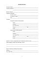
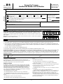


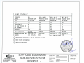
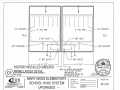


![Forms [packet] specific to Licensed Child Care](http://vs1.manualzilla.com/store/data/005750447_1-ace0dbf587046d14d311f9d21e5da3df-150x150.png)