1
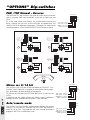
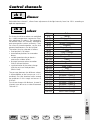
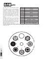
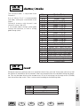
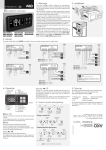
Victory250
user manual
automated luminaire
rel. 1.02
General warnings
Carefully read the warnings contained in this manual, since they supply important instructions concerning safety of installation, use and maintenance.
It is very important that this manual be kept with the equipment for future consultation.
In case of sale or transfer of the equipment to another user, ensure that this manual always
accompanies the equipment to allow the new owner to obtain information about the operation
and the relevant warnings.
• Not for residential use.
• After unpacking check the integrity of the equipment. In case of doubt, do not use the equipment,
and contact an authorized SGM Technical Service Centre.
• The packaging materials (plastic bags, expanded polystyrene, nails, etc.) must be kept out of reach
of children since they are potential sources of danger.
• This equipment may only be operated by adults. Do not allow children to tamper with the machine
or play with the product.
• The electrical and mechanical work necessary for the installation of the equipment must be carried
out by a qualified electrician or by a competent person.
• Before connecting the unit, check that the data on the registration plate is the same as that of the
electrical grid.
• Avoid using the equipment:
- in places subject to excessive humidity
- in places subject to vibrations or knocks
- in places with temperatures higher than 45°C or lower than 2°C
- Protect the equipment from excessively humid conditions
(the optimum values are between 35 and 80%).
• Do not disassemble or modify the equipment.
• Prevent inflammable liquids, water or metallic objects from penetrating the equipment.
• In case of spilling liquid on the equipment, immediately disconnect the power supply of the mixer.
• The minimum distance between the projector and the surface to be illuminated must not be less
than 1.5 m.
• In case of serious functioning problems, switch off the equipment and contact the nearest SGM
retailer or the manufacturer directly for inspection.
• Avoid opening the equipment: there are no parts repairable by the user.
• Never try to repair the equipment alone. Repairs carried out by inexpert persons may cause damage
Always insist on original spare parts.
Protect the environment: do not throw the packaging in your dustbin,
but return it to your retailer or take it to a collection point for special
waste disposal.
EN
I
D
F
E
appendice
page 1
or serious malfunctioning. Contact the nearest authorised Technical Service Centre.
Index
1
General warnings
2
Index
3
Main characteristics
3
Lamp
3
Optic system
3
Focusing
3
Mirror
3
Strobe
3
Dimmer
4
Iris
4
Shutter
4
Colour
4
Gobo
5
Technical characteristics
6
Positioning and focusing
6
Positioning
6
Focus adjustment
7
Victory 250 maintenance
7
Access to inside
7
Lamp mounting and replacement
7
Cleaning/ Periodic checks
8
Colour replacement
8
Gobo replacement
8
Start addresses
9
Victory connections
10
“Options” Dip-switch
10
Pan/Tilt - Normal/Reverse
10
Mirror 8/16-bit res.
10
Auto/Remote mode
Control channels
11
ch 1 - dimmer
11
ch 2 - colour
12
ch 3 - gobo
13
ch 4 - shutter/strobe
13
ch 7 - reset
page 2
10
Made in Italy by SGM Electronic
Printed in September, 1998 • Rel. 1.02
Main Characteristics
The intelligent projectors of the Victory series spring from a design philosophy which all SGM products
have for years had in common. These new scanners, because of their avant-garde performance, certainly take top place among the best in world-wide production. The accurate study of the functions,
the search for innovative materials, the continuous technical updating have led to the realization of a
certainly unique product: Victorys are projectors suitable for a multitude of applications.
The vast and pluridecennial experience of SGM in the sector of light control systems has allowed
developing a product with high reliability and precision, of which the mechanics, optics and electronics
are entirely designed by our own research laboratories. This allows absolute mastery of the know-how
and optimisation of the quality/price relation.
As every SGM product before commercialisation, the Victorys have brilliantly passed the long testing
period and the strict tests they have had to undergo - this is synonymous with high quality and reliability.
The particular care over the aesthetics, and the optimisation of the outer structure aimed at functionality, allow easy installation in any position and extremely fast technical intervention.
The Victorys are constructed in conformity with the CE regulations currently in force.
Lamp
The Victorys use an extra low-voltage incandescent halogen lamp with a 2-pin connector, without
doubt the ideal lamp for this type of projector, since it combines good reliability with long life (about
300 hours), It has surprising luminous power at ridiculously low cost, absolutely incomparable with
other metallic iodide lamps mounted on projectors of the same type.
Optic system
The special SGM-designed parabola able to concentrate the luminous beam, and the condenser lens in
selected glass with a high transmission coefficient, subjected to special multilayer antireflection treatment, exalt the brilliance and luminous power of the Victorys whose brightness is positively astounding.
Focusing
Focusing the Victorys is extremely easy, fast and with absolute precision from the screw panel located
on the front of the projector (Focus). Focusing is accurate on all the gobos as they are all arranged on
the same wheel.
Mirror
The mobile mirror of the Victorys has ultra-high reflection able to reduce the loss of luminous yield to a
minimum. The scanning time is 0.5 seconds for the 90° Pan and 0.3 seconds for the 180° Tilt.
Extremely elaborate software and the use of first-class motors have allowed obtaining a movement
capability which is ultrafast, precise and very linear even at lower speeds. Moreover, the Victorys
accept 16-bit control which ensures a linearity of movement unbeatable among the projectors in this
range. Mirror scanning can also be inverted to facilitate installation and programming.
The stroboscopic effect of the Victorys is extremely fast for a projector of this category and may be
adjusted by the operator to a frequency from 1 to 9 flashes a second.
Dimmer
The Victorys are also fitted with a dimmer function so that the light intensity may be dimmed from 0 to
100%.
EN
I
D
F
E
appendice
page 3
Strobe
Iris
The Victorys do not have a mechanical iris, but the 8-position gobo wheel has a position to shape the
luminous beam, thus obtaining a narrower beam which, for example, can be directed at a mirrored
globe, or used to satisfy any other special need. Since the gobo is interchangeable, the amplitude of
the luminous beam may be selected from the many available.
Shutter
A shutter is available on the Victorys, which may be activated instantaneously to block the luminous
beam output.
Colour
8 base colours are available on Victory (7+white) obtained through top-quality They are all easily interchangeable, so that also personal requirements can be satisfied.
The colours may be selected as follows:
• fixed positions, full colour
• intermediate positions for two-colour beams
• variable-speed rotation to obtain a spectacular rainbow effect
• passage from one colour to another with or without blackout.
• synchronization of the colour change with the music on fixed positions (Music Hard).
The passage between the different colours is imperceptible to the human eye as it is extremely fast
(the absolute fastest among the projectors in this range) and occurs in 0.08 sec.
Gobos
page 4
The Victory gobo unit consists of a single wheel with 7 images and one empty position. All the gobos
are easily interchangeable so that the operator may install new figures easily and quickly.
The gobo change occurs in fast imperceptible mode, or in analog mode with a slow passage from one
figure to the next.
Technical Characteristics
Power supply:
90÷260V - 50/60Hz - Universal, automatic voltage change.
Lamp:
250W 24V-EVC M/33, G6.35 connector - Life approx. 300 hours.
Absorbed power:
300 W
Optic unit:
Mirrored parabola with very high luminous yield, designed for Victory.
Optic system:
Mirrored parabola + 70mmø lens + 90mmø lens, screw focusing.
Lenses:
In glass with high transmission coefficient.
Mirror:
Ultra-high reflection, in special glass.
Electronics:
Entirely developed by engineers of the SGM Research & Development
Laboratory. Has a power supply card (CS 0207) and a logic card (CS 0208).
Settings:
By means of dip-switches, to address the control channels of the projector and
to set the selectable options:
- PAN/TILT scanning inversion;
- 8 or 16-bit mirror movement resolution;
- Control mode: Remote (from remote control), or Auto for automatic
functioning independent of the projector.
Motors:
5 a micro-stepper motors, 5 DC motors.
Input:
Digital serial signal DMX512 or RS232/423.
Control channels:
ch1 - dimmer / ch2 - colour / ch3 - gobos / ch4 - shutter/strobe / ch5 - pan
ch6 - tilt / ch7 - gobo rotation / ch8 - palette / ch9 - prism and prism rotation
ch10 - reset / ch11 - pan 16bit / ch 12 - tilt 16bit
Mirror movement:
Mirror rotation by means of 2 extra high-precision micro-stepper motors and
controlled by the relevant control card. Option to invert mirror scanning.
Safety regulations:
The Victorys are in conformity with current CE regulations.
Safety devices:
IP20 degree of protection. Automatic power cut-off in case of overheating or
cooling system operation failure.
Cooling system:
Forced through 1 axial fan.
Body:
In die-cast extruded aluminium. Epoxy-powder enamelling.
Mounting bracket:
In epoxy-powder enamelled steel. Installation position with adjustable
inclination over 110°.
Dimensions:
cm 18 x 65 x 35. Weight: Kg 13,5.
page 5
SGM Elettronica reserves the right to make improvements and modifications
to its products at any time.
Always refer the manual to the equipment it pertains to in order to avoid mistakes
and straying from the actual functions as illustrated in the manual.
EN
I
D
F
E
appendice
Positioning and Focusing
Positioning
To position the projector, the channels must be set as follows:
Channel 1
Channel 2
Channel 3
Channel 4
Channel 5/6
dimmer
colour
gobos
shutter/strobe
pan/tilt
100% open
white
no figure
open
centre position
Position the projector rotating it on its support bracket, then lock it in the desired position with the
knobs.
Focus adjustment
To adjust the lens, the channels must be set as follows:
Channel 1
Channel 2
Channel 3
Channel 4
Channel 5/6
dimmer
colour
gobos
shutter/strobe
pan/tilt
100% open
white
position on a figure
open
in position on the point where focus is desired
Focusing the Victorys is very easy, fast and with absolute precision through the screw knob located on
the front of the projector (Focus). Focusing is accurate on all the gobos as they are all arranged on the
same wheel.
Victory
focus
focus
Victory
focus
Victory
page 6
focus
Victory 250 Maintenance
Access to inside
Victory has a particular way of access to the inside of the projector. Remaining fixed as installed, the
projector can be opened exactly halfway in longitudinal direction, thus allowing easy access to the
inner parts in order to carry out any necessary operation, be it cleaning, lamp change or service of any
mechanical or electrical part.
To open the projector, unscrew the 2 knobs on the front (Fig. 1), taking care that the lower part does
not drop downwards suddenly when the screws are undone. A locking lever (Fig. 3) will automatically
hold it open at maximum travel.
fig. 3
Victory
focus
fig. 1
fig. 2
Lamp mounting or replacement
Projector cleaning / Periodic checks
Cleaning the optics - internally and externally - is determining for maximum luminous yield and should periodically be carried out. The cleaning frequency above all depends on the
place where the projector operates. In particular, a humid environment with a great deal of smoke or
dust favours greater accumulation of dirt on the projector optics. Clean with a soft cloth using normal
window-cleaning products or denatured alcohol, always carefully drying the parts. Clean the external
optics at least every 15-20 days and the internal optical unit (condenser lenses, parabola) and gobo unit
EN
I
D
F
E
appendice
page 7
WARNING: Before replacing the lamp:
- Evaluate the effective necessity to replace the lamp (average lamp life about 300 h).
- Disconnect the projector from the mains.
- If the projector was on, before opening it, wait for the lamp and the internal
mechanical parts to cool down (10÷30 minutes)
Remove the burnt-out lamp. Be extremely careful not to touch the optics, the
parabola and the lamp with bare hands, since the residuals subjected to high temperatures burn, causing the parts to blacken and irreparably damaging the lamp.
Proceed with mounting the new lamp placing it carefully in its housing.
FOR GOOD PROJECTION IT IS VERY IMPORTANT THAT THE LAMP FITS PERFECTLY IN THE SOCKET.
After each lamp replacement it is recommended to carry out a complete cleaning
cycle.
After carrying out the necessary operations, before pushing the lower part
towards the top (Fig. 2) to close the projector, release the locking lever lifting it
towards the top (Fig. 3). Screw down the 2 knobs one after the other, taking care
that these have properly hooked the lower part to prevent it from suddenly dropping downwards.
(including the rotation system) at least every 40-60 days.
To ensure an always perfectly efficient projector, a general overall inspection every 700 hours of operation is recommended. Checking of the electrical and mechanical parts must be carried out by technical
staff.
Colour replacement
Open the projector after disconnecting it from the
mains. If it was on, wait for the lamp and the internal
mechanical parts to cool down (about 30 minutes). The
colour wheel consists of two parts between which the
seats of the colour filters are located.
To replace them: with the finger very gently separate
the two locking discs at the point of the dichroic filter to
be replaced. Remove the filter and insert the new one.
Properly close the wheel and the projector.
Gobo replacement
A
Open the projector after disconnecting it from the
mains. If it was on, wait for the lamp and the internal
mechanical parts to cool down (about 30 minutes).
With the aid of a small screwdriver, remove the
spring (C), replace the gobo (B), reinsert the spring,
taking care to insert it perfectly on the special gobo
ring (A). Properly close the projector.
B
C
Start Addresses
For connection in DMX512 mode, each projector must appropriately be configured.
The start address is set with the dip-switch located on the back of the projector. The address can be
modified also when the projector is on.
1
2
4
8
16
on
on
on
on
on
on
1
2
4
8
16
32
64
128
256
on
32
64
128 256
on
1 2 3 4 5 6 7 8 9
1
2
4
8
16
32
64
128
256
1 2 3 4 5 6 7 8 9
1
2
4
8
16
32
64
128
256
1 2 3 4 5 6 7 8 9
1
2
4
8
16
32
64
128
256
1 2 3 4 5 6 7 8 9
page 8
Victory II PRO150 #1 (ch 01 ÷ 12)
Victory II PRO150 #2 (ch 13 ÷ 25)
Victory II PRO150 #3 (ch 26 ÷ 38)
Victory II PRO150 #4 (ch 39 ÷ 51)
Warning! Always refer to the numbers silk-screen printed on the Victory panel and not to those
on the dip-switch.
Victory Connections
The projector is fitted with a DMX512 and RS-232/423 input/output.
When making the start address settings, consider that 4 channels are used (channel 1 is not operational in this version).
For connection in a DMX network always use balanced microphonic cables type RF 60/12 2x0.25mm2
or similar and select a good quality to prevent malfunctioning of the projector.
To reduce interference it may be necessary to insert a network terminator on the last projector in the
DMX chain, realized with a 120Ω 1/4W resistor placed between pins 2 and 3 of the DMX connector.
Warning: The screening part of the cable (braid) must NEVER be connected to the system
earth, since this would lead to malfunctioning of the projector and the control units.
PUSH
Victory # n
PUSH
Victory #2
PUSH
Victory #1
DMX512 or RS-232 line
socket pin out
RS-232/423 connection
input
pin 1
comm
pin 2
- DMX
+ RS-232
4
3
1
RS-232
COMPUTER
OUT
25 PIN
CONNECTOR
2
output
1 2
DIGITAL SIGNAL
TD 2
4
5
2
1
3
GND 7
COMMON
VICTORY
5 PIN
CONNECTOR
3
5 4
page 9
pin 3
+ DMX
+ RS-232
5
EN
I
D
F
E
appendice
“OPTIONS” Dip-switches
PAN /TILT Normal - Reverse
O P T IO N S
The PAN and TILT dip-switches are used to invert vertical and horizontal scanning from top to bottom, from left to right and vice
versa.
Ex. In the case where two Victorys are installed one in front of the
other, moving the joystick to the left/right or top/bottom, the
Victorys will have opposite movements. Therefore, to make mirror
scanning uniform, act on PAN MOVE/TILT MOVE of one of these.
1 2 3 4
ON
OFF
TILT normal - reverse
PAN normal - reverse
MIRROR res 8 /16 bit
MODE auto/remote
OPTIONS
OPTIONS
1 2 3 4
1 2 3 4
TOP VIEW
TOP VIEW
TILT normal - reverse
PANT normal - reverse
MIRROR res 8 /16 bit
MODE auto/remote
TILT normal - reverse
PAN normal - reverse
MIRROR res 8 /16 bit
MODE auto/remote
TILT = 0
PAN = 0
TILT = 0
PAN = 0
CENTER POINT AREA
4
CENTER POINT AREA
3
TILT = 50 x
PAN = 50 x
TILT = 100 x
PAN = 100 x
TILT = 50 x
PAN = 50 x
TILT = 100 x
PAN = 100 x
Max. AREA DI LAVORO
Max. AREA DI LAVORO
OPTIONS
O P T IO N S
1 2 3 4
1 2 3 4
TOP VIEW
TOP VIEW
TILT normal - reverse
PAN normal - reverse
MIRROR res 8 /16 bit
MODE auto/remote
TILT normal - reverse
PAN normal - reverse
MIRROR res 8 /16 bit
MODE auto/remote
TILT = 100 x
PAN = 100 x
TILT = 100 x
PAN = 100 x
CENTER POINT AREA
1
CENTER POINT AREA
2
TILT = 50 x
PAN = 50 x
TILT = 50 x
PAN = 50 x
TILT = 0
PAN = 0
TILT = 0
PAN = 0
Max. AREA DI LAVORO
Max. AREA DI LAVORO
page 10
REGIA
Mirror res 8/16 bit
OPTIONS
The Victorys may also be 16-bit controlled on PAN/TILT. This
function, which normally is coupled to more professional projectors, guarantees absolute linearity of movement.
To activate this function the OPTIONS dip-switch 3 must be set
to ON.
In order to use the 16-bit control, the Victorys need 2 additional
control channels, therefore passing from 7 to 9 channels.
1 2 3 4
ON
OFF
TILT normal - reverse
PAN normal - reverse
MIRROR res 8 /16 bit
MODE auto/remote
O P T IO N S
1 2 3 4
Auto/remote mode
The Victorys can also function autonomously without the control
auxiliary. To activate this function the OPTIONS dip-switch 4
must be set to OFF. The projector will start running 8 resident
programs (AUTO) in a continuous cycle.
ON
OFF
TILT normal - reverse
PAN normal - reverse
MIRROR res 8 /16 bit
MODE auto/remote
Control channels
ch 1
dimmer
Adjustable from channel 1, allows linear adjustment of the light intensity from 0 to 100% according to
operator requirements.
ch 2
colour
On Victory the 8 base colours are multiplied
by a colour-temperature conversion filter,
thus obtaining 16 colours. The top-quality
38 (dichroic filters are carefully selected to
guarantee perfect colour uniformity. They
are all easily interchangeable, so that also
personal requirements can be satisfied.
The colours may be selected as follows:
• fixed positions, full colour
• intermediate positions for two-colour
beams
• variable-speed rotation to obtain a
spectacular rainbow effect
• passage from one colour to another
with or without blackout.
• synchronization of the colour change
with the music on fixed positions
(Music Hard).
Color
White
White + Yellow
Yellow
Yellow + Magenta
Magenta
Magenta + Cyan
Cyan
Cyan + Orange
Orange
Orange + Green
Green
Green + Blue
Blue
Blue + Red
Red
Red + White
Rainbow - speed 1
Rainbow - speed 2
Rainbow - speed 3
Rainbow - speed 4
Rainbow - speed 5
Rainbow - speed 6
Rainbow - speed 7
Rainbow - speed 8
Music hard change
page 11
The passage between the different colours
is imperceptible to the human eye as it is
extremely fast (the absolute fastest among
the projectors in this range) and occurs in
0.08 sec.
To activate change with blackout, channel 4
(shutter) must be set to a value of between
199 and 211.
Value
0÷9
10÷19
20÷29
30÷39
40÷49
50÷59
60÷69
70÷79
80÷89
90÷99
100÷109
110÷119
120÷129
130÷139
140÷149
150÷159
160÷170
171÷180
181÷191
192÷201
202÷212
213÷223
224÷233
234÷244
245÷255
EN
I
D
F
E
appendice
ch 3
gobo
The gobo wheel is adjustable from Channel
Value
Gobo
3.
0÷20
No gobo
All the gobos are easily interchangeable,
21÷40
Gobo 1
the light filter diameter is 34 mm. The gobo
selection is controlled by optical sensors
41÷60
Gobo 2
located near the wheel. The Victory gobo
61÷80
Gobo 3
unit consists of only one wheel with 7 ima81÷100
Gobo 4
ges and one empty position. All the gobos
Gobo
5
101÷120
are easily interchangeable so that the opeGobo 6
121÷140
rator may install new figures easily and
quickly.
Gobo 7
141÷160
The gobo change occurs in fast impercepti161÷177
Rotagobo - speed 1
ble mode, or in analog mode with a slow
178÷194
Rotagobo - speed 2
passage from one figure to the next.
195÷212
Rotagobo - speed 3
Selecting the rotagobo function, (running of
213÷229
Rotagobo - speed 4
figure adjustable to 4 preset speeds) allows
obtaining a special visual effect.
230÷255
Music Hard change gobo
Channel 3 interacts with channel 4. From
channel 4 the operator may select gobo change with blackout (values 186÷198), or slow gobo change
(values 225÷237).
1
7
6
2
page 12
5
3
4
ch 4
shutter/strobe
The shutter/strobe is adjustable from
Channel 4.
Use of “Music Flash” is recommended
(see table), which gives a remarkable visual
impact.
Channel 4 interacts with channel 2 and
channel 3 (values 186÷237).
It can enable colour change and/or gobo
change with blackout, as well as analog
gobo change (slow).
ch 7
Value
Shutter/Strobe
0÷9
Shutter closed
10÷19
Strobe - 1 fps
20÷29
Strobe - 1.39 fps
30÷39
Strobe - 1.65 fps
40÷49
Strobe - 1.94 fps
Strobe - 2.34 fps
50÷59
Strobe - 2.78 fps
60÷69
Strobe - 3.29 fps
70÷79
80÷89
Strobe - 3.91 fps
90÷99
Strobe - 4.56 fps
100÷109
Strobe - 5.45 fps
110÷119
Strobe - 5.98 fps
120÷129
Strobe - 6.98 fps
130÷139
Strobe - 7.85 fps
140÷149
Strobe - 9 fps
150÷159 Shutter Sync: audio low freq
160÷172
Flash Sync: audio low freq
173÷185
Flash Sync: audio high freq
186÷198 Shutter open & auto shade gobos
199÷211 Shutter open & auto shade colours
212÷224 Shutter open & auto shade gobos+colours
225÷237 Shutter open, low speed gobo change
238÷255
Shutter open
reset
Whenever necessary, perhaps due to an imperfect electric line, reset the Victory logic (which may feel
the effects of interference on the network when very powerful) from the controller driving the projector. This may be done thanks to the remote reset, first of all activating it on the logic circuit (CS0208)
from the relevant dip-switch. Then it can be used according to the following table:
EN
I
D
Reset
Off
Lamp histeresis
Reset
F
E
page 13
Value
0÷49
50÷234
235÷255
appendice
cod. M001090
Via Pio La Torre, 1 • 61010 TAVULLIA (PS) • ITALY •
Tel. 0721476477 • Fax 0721476170
[email protected] • www.sgm.it