1
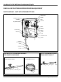
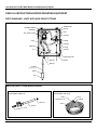
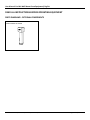
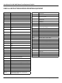
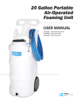
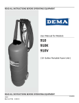
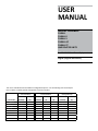
USER
MANUAL
MODEL NUMBER:
FI-WALL
FI-WALL K
FI-WALL V
FI-WALL AP
FI-WALL ST
AND RELATED UNITS
Pre-Mix Wall Mount Foam Equipment
English (Original Instructions)
This unit is available with several different configuration options. Use the following chart and example
item numbers to identify specific configurations and item numbers.
Acid-Proof Fittings?
Pump Seal Material
Discharge Wand Tip
No
Yes
Santoprene
Viton
Kalrez
Foam zero tip
Foam fan tip
ITEM NUMBER
(standard)
(AP)
(standard)
(V)
(K)
(standard)
(ST)
EXAMPLES:
-
-
-
-
-
-
-
FI-WALL
x
FI-WALL APV
FI-WALL ST
MY UNIT IS:
x
x
x
-
x
x
x
x
-
-
x
-
-
-
-
User Manual: Pre-Mix Wall Mount Foam Equipment| English
READ ALL INSTRUCTIONS BEFORE OPERATING EQUIPMENT
WARNING
Specifications:
Read this manual completely and understand the
machine before operating or servicing it.
Requirements:
• Read all instructions before installing or operating unit.
• Always wear appropriate personal protective equipment
(PPE) when operating or servicing unit.
Hose ........... 50 feet reinforced hose, 3/4 inch inside diameter
(15 meters reinforced hose, 19 mm inside diameter)
Foam Output................................... 20 to 45 gallons/minute
(75 to 170 liters/minute)
Foaming Distance ........................... 25 to 30 feet (7 to 9 meters )
Compressed Air Pressure Requirements: Air regulator (R25)
factory set at 50 psi (3.4 bar). Operating range is 40 to 80 psi (3
to 5 bar) with 5 to 10 CFM (141.6 to 283.3 l/min)
Liquid Temperature ........................ 40˚F to 100˚F (4.4˚C to 37˚C)
• Always follow all chemical safety precautions and
handling instructions provided by the chemical
manufacturer and Material Safety Data Sheet (MSDS).
Chemical Requirements: Follow all instructions from chemical
manufacturer and Material Safety Data Sheet (MSDS).
• If this unit is modified or serviced with parts not listed in
this manual, the unit may not operate correctly.
Air Operated Double Diaphragm Pump Models Offered:
• Never point the discharge wand at yourself, another
person, or any object you do not want covered in
chemical.
P56V: Polypropylene body with Viton diaphragm
• Always depressurize unit after use (as described in the
After Use Instructions). Always store unit depressurized,
with the discharge ball valve in the closed position.
• Do not exceed an incoming air pressure of 100 psi (7
bar).
• Do not exceed a fluid temperature of 100˚F (37˚C).
• Always flush the unit with fresh water for 5 minutes
when switching from an alkaline to an acid or an acid to
an alkaline.
P56: Polypropylene body with Santoprene diaphragm
P56K: Polypropylene body with Kalrez diaphragm
Acceptable Products:
Alkaline cleaners, Caustic cleaners, Sanitizers, and Acids
* D-Limonene may only be used with Kalrez pump
* Chlorine may only be used with Viton or Kalrez pump
DO NOT USE: All hydrocarbons
• Only use clean and dry air. Air must be filtered and free
of moisture or pump life will be diminished. If needed,
install an air dryer before unit.
• Do not use an air lubricator before the unit.
PROTECT THE ENVIRONMENT
Please dispose of packaging materials, old machine
components, and hazardous fluids in an environmentally safe
way according to local waste disposal regulations.
Always remember to recycle.
*Specifications and parts are subject to change without notice.
Model No.: FI-WALL, FI-WALL K, FI-WALL V, FI-WALL AP, FI-WALL ST
Page 2 of 8 | 07232013
User Manual: Pre-Mix Wall Mount Foam Equipment| English
READ ALL INSTRUCTIONS BEFORE OPERATING EQUIPMENT
Installation Instructions:
1. Remove all components from packaging.
2. Select desired area to mount the control box.
Note: We recommend mounting the control box at a
height of 6 feet or less. The chemical suction line must
reach the bottom of the chemical container. The bottom
of the chemical container should not be positioned higher
than the bottom of the control box.
3. Attach the control box mounting feet to the back of the
control box, using the four screws provided in the parts
package.
4. Mount the control box to the wall using four of the
screws and plastic anchors provided in the parts package.
Note: To drill holes for the plastic anchors, use a 5/16
inch drill bit.
5. Mount the hose hanger (SSHH-F) in a convenient location
using the remaining two screws and anchors provided in
the parts package.
6. Attach the discharge hose assembly (H34-50/H34-50AP) to the discharge hose barb (HBSS1234/HB1234) and
secure it with the larger hose clamp provided in the parts
package.
7. Connect the air inlet hose barb (HBSS1438) provided in
the parts package to the air inlet valve (BVB14) located on
the side of the control box. Then attach a 3/8 inch I.D. air
line from your air compressor to the air inlet hose barb,
and secure it with the smaller hose clamp provided in the
parts package.
Operation Instructions:
1. Follow all instructions from chemical manufacturer. Place
the chemical suction line into a container of pre-mixed
chemical solution.
2. With the discharge ball valve (HV60/HV34) in the closed
position, open the air inlet valve (BVB14).
3. Slowly open the discharge ball valve (HV60/HV34) to
begin foaming. The discharge ball valve (HV60/HV34)
should be completely open while foaming.
After Use Instructions:
We recommend flushing the discharge hose and depressurizing
the unit after each use.
1. Place the chemical suction line into a container of water.
2. With the unit running, open the discharge ball valve
(HV60/HV34), and allow the unit to be flushed with fresh
water for approximately 2-4 minutes or until all chemical
has been discharged from the system.
3. Shut off the air supply to the unit by closing the air inlet
valve (BVB14).
4. Open the discharge ball valve (HV60/HV34) to relieve any
pressure remaining in the unit.
5. Close the discharge ball valve (HV60/HV34) after all
pressure has been relieved from the unit. Store the unit
with the discharge ball valve (HV60/HV34) in the closed
position.
Maintenance Instructions:
To keep your foam unit operating properly, periodically perform
the following maintenance procedures:
Note: Before performing any maintenance, ensure that the unit
has been disconnected from the air supply and depressurized
according to the “After Use Instructions” above.
• Inspect the pump (P56/P56K/P56V) for wear and leaks.
• Inspect all hoses for leaks or excessive wear. Make sure all
hose clamps are in good condition and properly secured.
• Replace the filter (AFR25) located within the air regulator
(R25) as needed. Clean by unthreading the air regulator
bowl (ABR25) from the air regulator (R25).
• Check the chemical suction line and strainer for debris
and clean as needed.
• Drain your air compressor tank on a regular basis to help
extend pump life. An air source with a high moisture
content will accelerate pump wear. Note: If your air
source has a high moisture content, you may wish to
install a water separator (item number WS-20CFM, sold
separately) before the unit.
4. While the unit is running and discharging product, adjust
the needle valve (NV14Y), located inside the control box,
as needed to regulate the wetness or dryness of the foam
following the steps below:
a. Close needle valve (NV14Y) completely in clockwise
direction.
b. Open needle valve (NV14Y) in counter-clockwise
direction 3 complete turns.
c. Continue to open needle valve in ¼ turn increments,
allowing 30 seconds between adjustments, until
desired consistency of foam is achieved.
Model No.: FI-WALL, FI-WALL K, FI-WALL V, FI-WALL AP, FI-WALL ST
Page 3 of 8 | 07232013
User Manual: Pre-Mix Wall Mount Foam Equipment| English
READ ALL INSTRUCTIONS BEFORE OPERATING EQUIPMENT
Troubleshooting Instructions:
• Check to ensure that the discharge hose is uncoiled
properly, and that there are no kinks that could obstruct
fluid flow.
• Check the air regulator bowl (ABR25) and air filter (AFR25)
for debris such as water, oil, or rust particles. Clean by
unthreading the air regulator bowl (ABR25) from the air
regulator (R25).
• If the needle valve (NV14Y) is open too far, the pump
(P56/P56K/P56V) may cycle improperly due to lack of
air pressure. If this occurs, close and readjust the needle
valve (NV14Y) as described in Operation Instruction #4.
• Make sure proper foaming chemical and concentration
are being used.
• If air passes through the pump (P56/P56K/P56V) without
cycling, the pump needs to be replaced.
• If solution backs up into the air regulator bowl (ABR25),
the check valve (CV38) needs to be replaced.
• If foam comes out wet, no matter where the needle valve
(NV14Y) is positioned, the check valve (CV38) may need to
be replaced.
• Check for proper air pressure on the air gauge (AG100).
The air regulator (R25) is factory set at 50 psi (3.4 bar).
Operating range is 40 to 80 psi (3 to 5 bar) with 5 to 10
CFM (141.64 to 283.30 l/min).
• If the unit operates at a reduced pressure:
oo Check the air compressor supplying the unit. If the
pressure is less than 40 psi, turn the unit off until the
compressor can catch up.
oo If the air supply is 50 psi (3.4 bar) or above, check the
air gauge (AG100), which should read near 50 psi (3.4
bar). If the air gauge reads more or less than 50 psi
(3.4 bar), adjust the pressure by turning the knob on
the top of the air regulator (R25).
• Check the chemical suction line and strainer for debris or
damage. Clean or replace as needed. To prevent damage
to the unit, the strainer (STR14/FV2) must always be used.
Model No.: FI-WALL, FI-WALL K, FI-WALL V, FI-WALL AP, FI-WALL ST
Page 4 of 8 | 07232013
User Manual: Pre-Mix Wall Mount Foam Equipment| English
READ ALL INSTRUCTIONS BEFORE OPERATING EQUIPMENT
PARTS DIAGRAMS - UNITS WITH STANDARD FITTINGS
CONTROL BOX ASSEMBLY
HBSSEL1438
NV14Y
P56-BRKT-SCREW
R25
P56-BRKT
SN1414
P56, P56K or P56V
BVB14
SN1414
SST12HB38-P
SSA14
HBSS1234
AG100
CV38
PB16138-LATCH
R25DT
H38B-H
(Available per ft.)
SHW3
HB1438
STR14
HOSE AND ZERO TIP FOAM WAND ASSEMBLY
ITEM NUMBER: SSWA38-HA50
ZERO TIP FOAM WAND ASSEMBLY
ITEM NUMBER: SSWA38
FAN TIP FOAM WAND ASSEMBLY
ITEM NUMBER: PWA34-ST
50 ft (15 m) HOSE ASSEMBLY
ITEM NUMBER: H34-50
HBSS1234
HV60
SN1212
PW10
ST80200
H34B-H
(Available per ft)
HBSS1234
HV60
HHSB1238
HBSS1234
W387
SSC34
Model No.: FI-WALL, FI-WALL K, FI-WALL V, FI-WALL AP, FI-WALL ST
Page 5 of 8 | 07232013
User Manual: Pre-Mix Wall Mount Foam Equipment| English
READ ALL INSTRUCTIONS BEFORE OPERATING EQUIPMENT
PARTS DIAGRAMS - UNITS WITH ACID-PROOF FITTINGS
CONTROL BOX ASSEMBLY
HBSSEL1438
NV14Y
P56-BRKT-SCREW
P56-BRKT
R25
P56, P56K or P56V
SN1414
BVB14
CV38
SN1414
HB1238
SSA14
T5
AG100
PB16138-LATCH
R25DT
HB1238
HB1234
H38B-H
(Available per ft.)
SHW3
FV2
HOSE AND ZERO TIP FOAM WAND ASSEMBLY
ZERO TIP ACID-PROOF FOAM WAND ASSEMBLY
ITEM NUMBER: PWA34-AP
50 ft. (15 m) ACID-PROOF HOSE ASSEMBLY
ITEM NUMBER: H34-50-AP
H34B-H
(Available per .)
HHPB1214
SSC34
HB3434
SSC34
PW10AP
HB3434
HV34
Model No.: FI-WALL, FI-WALL K, FI-WALL V, FI-WALL AP, FI-WALL ST
Page 6 of 8 | 07232013
User Manual: Pre-Mix Wall Mount Foam Equipment| English
READ ALL INSTRUCTIONS BEFORE OPERATING EQUIPMENT
PARTS DIAGRAMS - OPTIONAL COMPONENTS
WATER SEPARATOR
ITEM NUMBER: WS-20CFM
Model No.: FI-WALL, FI-WALL K, FI-WALL V, FI-WALL AP, FI-WALL ST
Page 7 of 8 | 07232013
User Manual: Pre-Mix Wall Mount Foam Equipment| English
READ ALL INSTRUCTIONS BEFORE OPERATING EQUIPMENT
ITEM NUMBER
DESCRIPTION
AG100
1.5 INCH DRY MODEL 20 DUAL SCALE GAUGE
BVB14
AIR INLET VALVE - VA BRS 025-4F4F-BT, NICKEL
CV38
PVC CHECK VALVE 3/8 BARBS - SS SPRING
EC14-2
OETIKER CLAMP 13.8
F34SS-L
SS CRIPM FERRULE 1.90inches X 1.5 inches LONG
FV2
PB16138-GSKT
NEOPRENE GASKET 0.220 INCH ROUND CORD STOCK 61.125 INCHES
PB16138-LATCH
LATCH FOR PB16138
PB16138-PIN
STAINLESS STEEL HINGE PIN FOR CONTROL BOX PB16138 1/8 x 4 3/4 x 1/2inches
PBFT-PP
MOUNTING FEET FOR POLYBOX - PB16138 POLYPROPYLENE
FOOT VALVE, VITON, BLUE
PL16138
FWLG14
.569 ID X 1.28 OD X .08 THICK FLAT WASHER SS 18-8
CONTROL BOX LID - POLYPROPYLENE - 16x13x8 - HINGED
LOCKABLE LID
FWP12
7/8 ID X 1.5 OD X 0.05 THK SSFW
PW10
3/4in BLACK POLY PRO X 10in - FPTBE - SCH.80
FWP78
7/8in BY .137 BY 1 1/4in FLATWASHER 18-8 PLN
PW10AP
3/4in BLACK POLY PRO X 10in - FPTOE & MPTOE - SCH.80
H14B-H
1/4 INCH BLUE HOSE- GOODYEAR HORIZON - Available
per ft.
R25
AIR REGULATOR - 1/4fpt TWO PORT 1/8fpt TWO PORT INCLUDES FILTER AND BOWL
H34B-H
3/4 INCH BLUE GOODYEAR HORIZON HOSE - Available
per ft.
AFR25
AIR FILTER for R25
ABR25
METAL AIR BOWL for R25
H38B-H
3/8 INCH BLUE GOODYEAR HORIZON HOSE - Available
per ft.
R25DT
S1034FHL
10 X 3/4 PHIL FLAT HI-LO THRD SCREW 18-8
HB1234
1/2in MPT X 3/4in HOSE BARB
SHW3
3in LONG COATED WEIGHT
HB1238
1/2in MPT X 3/8in HOSE BARB
SN1212
1/2in HEX STAINLESS STEEL NIPPLE
HB1438
1/4in MPT X 3/8in HOSE BARB (PLASTIC)
SN1414
STAINLESS 1/4MPT X 1/4MPT NIPPLE
HB3434
POLY HOSE BARB 3/4in X 3/4in
SSA14
SS304 MALE/FEMALE ADAPTOR 1/4 NPT X 1/4 NPT
HBSS1234
STAINLESS HOSE BARB 1/2 X 3/4
SSC34
WORM GEAR CLAMP, S/S (.75-1.25)
HBSS1438
STAINLESS HOSE BARB 1/4 MPT X 3/8 BARB
SSC38
WORM GEAR CLAMP, S/S (.25-.63)
HBSSEL1438
STAINLESS HOSE BARB ELBOW 1/4 INCH NPT X 3/8 HOSE
BARB
SSHH-F
S.S. LASER CUT HOSE HANGER - FLAT STOCK
HBSSEL1814
304 STAINLESS ELBOW 1/8 INCH NPT X 1/4 INCH HOSE
BARB
SST12HB38-P
STAINLESS TEE COMBO 1/2in FPT X 3/8 in BARB
ST80200
VEEJET NOZZLE, 80200
HHPB1214
HEX HEAD POLY REDUCER BUSHING 1/2in X 1/4in
STR14
40 MESH SUCTION LINE STRAINER 1/4 MNPT
HHSB1238
HEX HEAD S.S. REDUCER BUSHING 1/2in X 3/8
T5
1/2 POLY TEE
HV34
3/4in POLY BALL VALVE
W387
HV60
1/2in STAINLESS BALL VALVE - w/ WELDED NUT
S.S. 304 SPRAY WAND 3/8in MPT X 7in LONG - THREAD
ON ONE END
NV14Y
FLOW CONTROL VALVE - INCLUDES BLACK KNOB
WMS14
14 X 1 1/4 HEX W/H SMS SLOTT, S/S
WMS14A
5/16 X 1 1/2 STRAIGHT PLASTIC ANCHOR
WS-20CFM
TSUNAMI WATER SEPARATOR 20 CFM
NV14Y-HNDL
KNOB FOR 2839-1/4 NEEDLE VALVE
P56
5700 PUMP WITH SANTOPRENE SEALS - INCLUDES HOSE
BARBS, AIR FITTING, AND AIR PORT
P56K
5700 PUMP WITH KALREZ SEALS - INCLUDES HOSE BARBS
P56V
5700 PUMP WITH VITON SEALS - INCLUDES HOSE BARBS
20756103B
Polypro G57 Air Port x HB Straight, w/ Viton o-ring
HB14P
1/4in BRASS HB AIR FITTING /G57/P56 HB5638
HOSE BARB FOR P56 PUMP
HB5638K
HOSE BARB FOR P56K PUMP
HB5638V
HOSE BARB FOR P56V PUMP
P56-BRKT
PUMP BRACKET- STAINLESS STEEL
P56-BRKT-SCREW
HI LO SCREW FOR RETAINING P56-BRKT
PB16138
POLYPROPYLENE CONTROL BOX - WORKING DIMS
16x13x8 - PUMP MOUNT
Model No.: FI-WALL, FI-WALL K, FI-WALL V, FI-WALL AP, FI-WALL ST
CLEAR TUBING FOR R25 DRAIN
Page 8 of 8 | 07232013