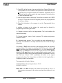
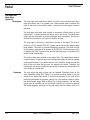
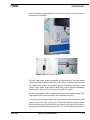
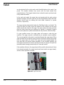
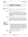
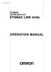
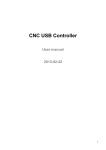
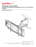
1
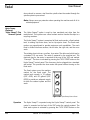
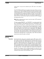
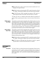
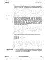
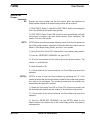
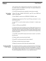
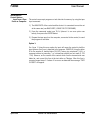
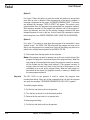
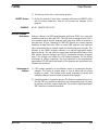
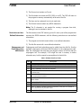
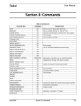
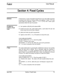
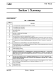
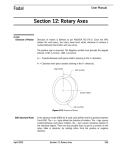
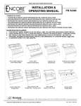
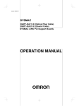
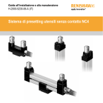
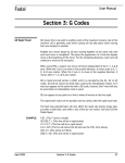
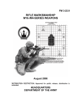
Fadal
User Manual
Section 19: Miscellaneous
Flood Coolant
Through the Spindle
(Optional)
Description
The Coolant Through the Spindle option provides coolant flow through the
spindle. The system has its own pump and electrical system, separate from the
standard flood coolant system. The main power switch for this system is
located in the rear of the machine and is labeled “Coolant Through Spindle.”
The coolant through main disconnect switch must be in the on position to
activate the coolant through system.
The SETP command allows the operator to select M7 or M8 for flood coolant.
When M7 is selected for flood coolant, M8 is used to activate the coolant
through the spindle option from the program. When M8 is selected for flood
coolant M7 is used to activate the coolant through the spindle option from the
program. The M9 code will cancel the M7 or M8 codes.
Special hollow retention knobs need to be fitted into the ends of tool holders,
which are intended for use with special tools that allow for coolant through the
tool. Because these retention knobs are hollow, their manufacturer
recommends usage with tools that have no side cutting pressure. The thin side
walls of these special retention knobs may fracture when using side cutting
tools like end mills, fly cutters, face mills etc. When the retention knobs fracture
and break, the tool will fall out of the spindle.
Note: Tools with side cutting pressure require solid retention knobs. Special
filters may be required to be retrofitted to the system if micro sized grit is in
the coolant. The grit can damage the rotating seals in the coolant through
system. If this seal is destroyed, the coolant will leak out of the seal and
damage the belt or other systems in the head area. These filters would be
supplied and provided by the user as to suit their particular need.
If the coolant through the spindle system is activated when a tool is in the
spindle, which has a solid designed retention knob, pressure will build up
behind the retention knob. When the solid tool holder is removed from the
spindle, either by hand of from a tool change, the pressurized coolant will spray
out from the flange area. It is suggested to used the tool changer, with the
April 2003
Section 19: Miscellaneous
465
Fadal
User Manual
doors closed, to remove a tool from the spindle when the coolant through the
spindle system is pressurized.
Note: Always wear eye protection when operating the machine and all of its
added equipment.
Hydro Sweep
(Optional)
Hydro Sweep™ Chip
Removal System
The Hydro Sweep™ option is used to clear machined part chips from the
machine tool. This system uses a flood coolant wash to transfer the chips to a
recycling container.
The Hydro Sweep™ system is comprised of flood wash nozzles, a flood coolant
tank, a rotating chip drain drum, and a chip ejector shoot. The flood wash
nozzles are prepositioned to provide maximum wash capabilities. The wash
flood is divided into three sections, the left side, the right side, and the cross
wash.
The rotating drum is driven, on rollers, by a motor. The rollers are belt driven by
a standard 110 vac motor. The motor is powered by the machine tool. The
electrical plug for the motor is mounted to the rear of the VMC and marked
“Conveyer”. The drum is activated by pressing the CYCLE START button on the
Hydro Sweep™ control panel. The drum may also be plugged into a standard
wall socket. This provides the drum motor with power without turning on the
flood wash.
The flood system uses the machine
coolant for the flood wash. The
coolant tank capacity is 70 gallons
(VMC 4020) and 85 gallons (VMC
6030) to provide an adequate supply
for both the coolant system and the
wash.
40
60
20
80
0
100
TRANSFER 1
40
60
20
80
0
100
TRANSFER 2
CYCLE START
Figure 19-1 HydroSweep Control Panel
Operation
466
The Hydro Sweep™ is operated using the Hydro Sweep™ control panel. The
control is mounted on the front of the VMC under the control pendant. The
flood wash system is activated by pressing the CYCLE START button on the
Section 19: Miscellaneous
April 2003
Fadal
User Manual
control panel. It may also be activated by the M20 code in the machine
program.
The CYCLE START and M20 code are toggles for the system. Either can turn the
system on or off. Press the button once to active the system and press it again
to deactivate the system. The M20 operates the same way. The first time the
code is performed in the program, the system is activated. The second time it
is performed the system is deactivated. When the system is used, by either of
these methods, the flood wash and drum are activated or deactivated. To
activate the drum without the flood wash, the drum motor MUST be plugged
into another power source.
Note: When an alternate power source is used, the drum is NOT activated by
the CYCLE START or M20.
The knobs marked TRANSFER 1 and TRANSFER 2, are used to set the flood
time. The TRANSFER 1 knob controls the cross wash. The TRANSFER 2 knob
controls the left and right wash. The flood has four cycles. The cycles rotate in
sequence from the cross wash, to the left wash, to the cross wash, to the right
wash. This sequence is continual until the CYCLE START button is pressed.
Only one wash cycle is on at any time. As one cycle starts the other stops. The
flood wash duration for each cycle position is determined by the TRANSFER
knob settings. The knobs are adjustable from 0 to 100 percent. With the knob
at 0 the wash cycles for three seconds. At 100 percent the wash cycles for
thirty seconds. The rotating drum lifts the chips to a drainage tray. Chips are
moved from the drainage tray to a recycling bin by a ram. This ram moves at
preset intervals when the system is activated.
Automatic Doors
(Optional)
Description
April 2003
The Automatic Door option may be operated using the M80, (open), and the
M81, (close). The doors ONLY operate with the M functions when they are in
the interlocked position. The interlocked position is when the doors are locked
into place on the pneumatic valves. When the doors are in the interlocked
position, the M80 code activates the pneumatic valves to open the doors.
When in the open position, the doors may NOT be closed manually. When in
the closed position, the door interlock may be manually disengaged to open
and close the doors. The door interlocks may be manually released by opening
the doors by hand. This requires slightly more pressure than without the
interlocks. The interlocks may be engaged manually by pulling the doors
closed, by hand, until the interlock engages. The interlocks must be engaged
manually to open the doors with the pneumatic valves.
Section 19: Miscellaneous
467
Fadal
User Manual
Note: An M20 code is used to close the doors when the machine tool is not
equipped with a general indexer.
Note: When the doors are closed and the M20 is coded, the machine will wait
for a signal. To override this condition, open and close the doors manually.
Note: The M20 code is ONLY used when the machine is NOT wired for a
general purpose indexer. Use the M81 code when there is an indexer.
The doors will come to a complete closed position before the program will
continue. When a general purpose indexer is used, the doors will close with an
M81.
M80 Automatic
Doors Open
This function is used to open the automatic doors. When the doors are in the
interlocked position, this code activates the pneumatic valves to open the
doors. When in the open position, the doors may NOT be closed manually.
When in the closed position, the door interlock may be manually disengaged to
open and close the doors. The interlocks must be engaged manually to open
the doors with the pneumatic valves. The interlocks may be engaged manually
by pulling the doors closed, by hand, until the interlock engages.
M81 Automatic
Doors Close
This function is used to close the automatic doors. When the doors are in the
interlocked position, this code activates the pneumatic valves to close the
doors. When in the open position, the doors may NOT be closed manually.
When in the closed position, the door interlock may be manually disengaged to
open and close the doors. The interlocks must be engaged manually to open
the doors with the pneumatic valves.
Note: When the doors are closed and the M81 is coded the machine will wait
for a signal. To override this condition, open and close the doors manually.
Note: This function is ONLY used when the machine is wired for a general
purpose indexer. Use the M20 code when there is no indexer.
Servo Coolant
(Optional)
Description
468
The Servo Coolant is an option that requires the appropriate software version
and hardware. The M7.1 or M8.1 activates the Optional Servo Coolant and
Coolant one (Flood). The SETP command allows the operator to select M7 or
M8 for flood coolant. The H word must be specified before programming the
M7.1 or M8.1.
Section 19: Miscellaneous
April 2003
Fadal
User Manual
The servo coolant option has been designed to allow the user to program a
direction of coolant flow. This coolant flow may be directed onto the tool or
directly onto the part to cool and wash away chips.
The servo coolant will be assigned to the A axis. If a rotary table is on the VMC,
it will have the A axis and the servo coolant will then have the B axis. When in
JOG mode, the servo coolant may be moved by jogging in the A or B axis (see
SETP page, set parameter for A or B ratio option to COOLANT).
The CS Procedure
When the VMC is powered on the servo coolant nozzle will find its own COLD
START zero position by seeking the spindle housing and backing off 10.0
degrees. The nozzle is moved towards the spindle until the movement is
obstructed. When the user COLD STARTS the VMC the Servo Coolant will again
seek the alignment position. At this point the nozzle is moved back by 10
degrees and Cold Start position is set. The range of motion is limited to 0 to 45
degrees from this CS position. The Cold Start will time out after 15 seconds.
The external override potentiometer knob must be straight upward in the OFF
position before Cold Starting the VMC.
The Servo Coolant will also have an external override potentiometer knob
located on the right side of the doors on the Chip guard. When this override is
straight up, the display will show OFF. If the knob is rotated, the amount
overridden will be displayed to the right of the position display. This knob will be
active after CS for all modes of operation and may be locked in or out with the
M48.1 and M49.1 codes.
When the control is in AUTO or MDI the position display will be as follows:
X 0.0000 0
Y 0.0000 0
Z 0.0000 0
A0
OFF
The Axis Position Display is modified to allow display for override pot. The
numeric display to the right the position display is now replaced by the value of
the override pot. This display will be in degrees (A or B axis only). This display
is active after Cold Starting the machine providing the servo coolant ratio is
selected in the SETP parameter page. Override pot should be in OFF position at
CS.
Setup Procedure
April 2003
1) Return the nozzle to the HOME position by using the HO command or by
using JOG mode to jog the nozzle back to the CS zero position. The override
potentiometer must be in the off position.
Section 19: Miscellaneous
469
Fadal
User Manual
2) From MDI, call the first tool to be used with the Servo Coolant. With this tool
in the spindle turn on the coolant. Next position the coolant flow onto the
tip of the tool by using the manual Pulse Generator. Adjustment may be
made later for the nozzle to point to the outer diameter of the tool by using
a P word and diameter value.
3) Note the degree value on the display. This will be the value for the L WORD
on the M7.1 line for the first tool. No negative position may be programmed
for the Servo Coolant.
4) Place this information in the program to use the Programmable Servo
Coolant.
In addition to turning on the coolant, the nozzle may be directed by
programming the following parameters:
L = Degrees to point to the first tool programmed. The L word initializes the
coolant nozzle angle.
P = Optional diameter / radius of tools in program. This makes an adjustment
outward or inward.
Q = Optional length override. This is to modify the nozzle adjustment up or
downward. The calculation is normally made from the value in the tool length
offset table.
For example, if Tool 3 needs the nozzle to be adjusted upward, the calculation
must be changed. To change the calculation the M7.1 line must include a Q
word. If the current value in the tool table offset 3 is -22.39 by adding one inch
to this value, the Q word will be -23.39. The program will now use the Q word
instead of the H word value to aim the programmable coolant upward 1 inch.
This change now adjusts the original setup parameter programmed for the first
tool. The next H word / M7.1 combination will return to the original
programmed setting. The Q word does not affect the tool length offset or
change any values in the tool table.
The program line will read as follows:
N124 H3 D3 Z1.5 The tool length offset is -22.39
N125 M7.1 Q-23.39
Note: M48.1 and M49.1 enables and disables the override pot. This is to
allow maximum movement to the nozzle even when the override pot is not
at zero.
470
Section 19: Miscellaneous
April 2003
Fadal
User Manual
EXAMPLE:
Continuous Sweep
Mode for the Servo
Coolant
N1 O1 (PART 1234
N2 M6 T1 (TOOL #1 , 3 INCH SHELL MILL
N3 G0 G90 S3200 M3 E1 X0 Y0
N4 H1 D1 Z.1
The H word must be called before the M7.1 code
N5 M7.1 L10.0 P3.0
Servo coolant on, Flood coolant on M7.1Read length of tool 1 and place nozzle
at the L of 10 degrees from CS position this offset now sets the origin of the
nozzle for this program. All nozzle aim will be adjusted from here.
*****cut part*******The P moves nozzle outward to the edge of inserts on the
3.0" shell mill
N22 M6 T2 ( .25 END MILL
N23 G0 G90 S3400 X0 Y0
N24 H2 Z1.5
N25 M7.1 Servo coolant on, Flood coolant on M7.1
*****cut part*******Read length of tool 2 and point nozzle to center tip of tool 2
N98 M9 Coolant off
N122 M6 T3 ( .5 END MILL
N123 G0 G90 S3400 X0 Y0
N124 H3 D3 Z1.5
N125 M7.1 P.5 Q-23.39
Servo coolant on as defined for the first tool called in program. Read length of
tool 3 and move nozzle to center of tip of tool 3. The P changes*****cut
part*******The Q-23.39 now moves the length upward 1.0 “ to adjust
preference
N1100 M9 Coolant off
Use of the reciprocation with the servo coolant will continuously sweep the
nozzle across the tool and part clearing / cooling the entire tool and part.
M14 Reciprocation for the B (Continuous sweep mode -Servo coolant option)
M15 Reciprocation for the A (Continuous sweep mode -Servo coolant option)
Use of the reciprocation with the servo coolant will continuously sweep the
nozzle across the tool and part. The servo coolant nozzle has a axis range of 0
to 45 degrees only.
EXAMPLE:
April 2003
G90 A10. X-3.0 M7
G1 F1000.0 A15.
M15
X6.0 G1 F25.0 The smaller the feedrate, the more times A will reciprocate
M10
Section 19: Miscellaneous
471
Fadal
User Manual
Chip Auger and
Wash Down
(Optional)
Description
The chip auger and wash down option is used to clear machined part chips
from the machine tool. This system uses a flood coolant wash to transfer the
chips to the front of the machine where a mechanical screw (auger) removes
the chips.
The chip auger and wash down system is comprised of flood outlets, a flood
coolant tank, a rotating mechanical auger and a chip shoot. The flood wash
outlets are pre-positioned to provide maximum wash capabilities. The flood is
divided into two sections: the right side and the left side.
The chip auger is driven by a shaft that is pinned to the auger. The shaft is
driven by a ¾ HP standard 240 VAC 3 phase motor with a ninety degree angle
head adapter. The motor is powered through the machine. The electrical plug
for the motor is mounted at the bottom of the CNC Box. The flood pump is also
a standard 240 VAC 3 phase motor and the electrical plug is mounted at the
bottom of the Junction Box.
The wash system uses the fluid in the coolant tank. The coolant tank capacity
is approximately 70 gallons to provide an adequate supply for both the coolant
system and the wash. The coolant tank has a set of baffles (screens) inside the
tank to filter out chips that get past the bottom pan screen. Therefore, the
coolant tank will have to be cleaned periodically to remove any accumulation of
chips inside the coolant tank.
Operation
472
The chip auger and wash system can run together (Standard Mode) or the
wash separately (Wash Only Mode). The normal operating mode is with the
switch in the Auger Wash mode. A control box mounted on the front of the
machine (underneath the pendant control) has a two position switch to select
the desired mode, Auger Wash or Wash Only. In both conditions, the side door
panels must be installed and the front doors closed for the system to operate.
The coded magnetic interlocks on the side panels and front doors must be in
Section 19: Miscellaneous
April 2003
Fadal
User Manual
their closed state (normal operation when the front doors are closed and the
side panels are installed).
Figure 19-2 Control Box
Figure 19-3 Coded Magnetic InterLocks
The chip auger wash system is activated and deactivated by the lower button
on the control panel (labeled Start/Stop). The button is pushed once to activate
the auger wash system and pushed again to deactivate the auger wash
system. Either mode, Auger Wash or Wash Only, can be stopped immediately
by opening the front doors or removing one of the side panels.
The chip auger/wash system cycle can also be activated by programming M20.
Programming M20 again turns off the chip auger/wash system.
In the auger mode (Auger Wash), the auger continuously runs and the wash
system cycles. The wash cycle time is a fixed off cycle time (time between
when the wash shuts off and when the next wash cycle starts). Both sides of
the machine are washed at the same time. The wash duration time (on time)
April 2003
Section 19: Miscellaneous
473
Fadal
User Manual
can be adjusted by the cycle wash control (middle knob on the control box
panel). The shortest duration time occurs with the knob rotated fully
counterclockwise. The longest duration time is when the wash cycle time knob
is fully rotated clockwise.
In the wash only mode, the auger does not operate and the wash system
operates normally. The wash cycle time can be manipulated to adjust the wash
duration (on/off time) by rotating the knob either clockwise or counter
clockwise, respectively.
The auger operates automatically when the Start/Stop button is activated. The
auger will move the chips across the bottom of the machine as the wash
system washes the chips into the auger. The auger pushes the chips out of the
push-out shoot where they are collected for removal. A standard 55-gallon
drum can be placed on a pallet underneath the chip shoot to collect the chips.
If a jam condition occurs, the auger motor will reverse to clear the jam
condition. The auger reversal is controlled by an overload current condition.
The current supplied to the motor is monitored through the auger board. When
a jam condition occurs and the supply current to the motor exceeds the current
limit, the auger motor will reverse. The auger will reverse approximately 3-5
turns and then will resume normal operation. If the overload condition still
exists (the reversal did not clear the jam the first time), the auger will repeat the
reversal/forward clearing procedure up to 5 times per minute.
If the condition still exists, the auger board will trip and the obstruction will have
to be cleared manually, the auger board reset (reset switch on auger board),
and the normal operation resumed.
Figure 0-1 Auger Board Reset
474
Section 19: Miscellaneous
April 2003
Fadal
User Manual
Dual Arm Tool
Changer
Commands
DD
Displays the bucket number and the tool number table, and identifies the
bucket number located at the bucket ready position with an asterisk.
1) SWAP TOOLS- Option 1 within DD is SWAP TOOLS, which will exchange the
Tool in the Spindle for the bucket ready position.
2) SORT TOOLS- Option 2 within DD will sort the tools automatically until each
tool number is located in the same bucket number. Upon completion, Tool
number 1 will be in the Spindle.
SETTO
SETTO without a number parameter following resets all of the tool numbers to
that of the bucket numbers, regardless of where the tools are located, and sets
bucket 1 at the bucket ready position, and tool 1 in the spindle.
1) Using Turret CW or Turret CCW, rotate bucket 1 to the bucket ready position.
2) From the <ENTER NEXT COMMAND> line, type SETTO.
3) All of the tool numbers will be reset to that of the bucket numbers. Tool
number 1 is in the Spindle.
4) Check the table in DD.
5) If Turret rotates in the incorrect direction, the Turret Motor may need to be
rephased.
SETTO,#
SETTO,# is used to reset the Turret locations by specifying that “#” is the
number of the bucket (not the tool number) located at the bucket ready position
and ready to be exchanged. The remaining bucket and tool numbers are
recovered as the sequence is retained.
1) Rotate the Turret using Turret CW or Turret CCW at least one position until
the desired bucket number (not tool number) is at the bucket ready position.
2) If Turret rotates in the incorrect direction, the Turret Motor may need to be
rephased.
3) From the <ENTER NEXT COMMAND> line, type SETTO,# where # is the
bucket number of the bucket now at the bucket ready position, and ready to
exchange tools.
April 2003
Section 19: Miscellaneous
475
Fadal
User Manual
4) The sequence of the remaining tools in the Turret is not changed, and the
new bucket numbers are updated in the DD table. The asterisk identifies the
bucket in the bucket ready position.
5) The SETTO,# procedure may be repeated as many times as needed.
Tool Loading
Procedure
1) From MDI mode, (MANUAL DATA INPUT), type M19, press ENTER and
START to orient Spindle.
2) Press MANUAL to switch to the <ENTER NEXT COMMAND> mode.
3) Rotate the Turret using Turret CW or Turret CCW keys until bucket 1 is in the
bucket ready position.
4) Type SETTO to reset the bucket numbers with bucket 1 at bucket ready
position.
5) Return to MDI by pressing MANUAL.
6) Load the first tool into the Spindle by pressing TOOL IN/OUT and insert into
the Spindle. Notice which of the two keyslots in the tool holder is deeper, or has
a protruding setscrew. Align the tool so that the deeper keyslot faces forward
and does not have any protruding setscrew to interfere with the alignment key
on the arm of the ATC.
7) Type M6T2, and the DATC will place the first tool in bucket 2, and wait for
the second tool.
8) Similarly, load the second tool into the Spindle.
9) Type M6T3, and the second tool will move to bucket 3.
10) Similarly, load the third tool into the Spindle.
11) Repeat as necessary until all of the tools have been loaded.
Operating the DATC
from a Program
476
The commands used within a program to operate the Dual Arm Tool Changer
are the same codes as the Geneva and Servo-Turret toolchangers. The call for
a tool change can take advantage of the ability of the DATC to pre-stage the
next tool into the bucket ready position. This is accomplished by commanding
Txx and M6 independently. (Do not use T-xx as in previous versions.)
Section 19: Miscellaneous
April 2003
Fadal
Miscellaneous
Control Options
Input from a Tape
Punch or Computer
User Manual
The control can accept programs or tool data into its memory by using the tape
input command.
1) The BAUD RATE of the control and the device it is connected to must be set
at the same rate (see BAUD RATE, USING THE CD COMMAND).
2) From the command mode type TA,1,# (where # is an error option see
below), then press the ENTER button.
3) Prepare the tape punch or the computer, connected to the control, to send
the program or tool data.
Option 1:
For # type 1. Using this error option for input will cause the control to halt the
input process if an error is detected in the program. EXAMPLE: Using the letter
O for the number 0, double letters (XX.152), minus sign misplaced (-Y.45), a
comment without a preceding * or, a dimension without an axis word (X.125
.756). Observe, on the screen of the control which line the transmission was
halted at, and correct this line at the text editor or Teletype. After this line is
corrected repeat steps 1-3 above. If no errors are detected the message “TAPE
IS GOOD” will appear.
April 2003
Section 19: Miscellaneous
477
Fadal
User Manual
Option 2:
For # type 2. When this option is used the control will continue to accept data
even after an error is detected. When transmission of the data is complete, a
message is displayed on the screen “# ERROR(S) READING TAPE.” If no errors
are detected the message “TAPE IS GOOD” will appear. This option is only
recommended when the program being transmitted has sequence numbers.
With sequence numbers in the program the operator can list the program, if
errors are detected, and look for the missing sequence numbers that were
dropped because of errors in the line. Use the insert (IN) command to replace
the missing lines. (see INSERT PROGRAM LINES, USING THE IN COMMAND)
Option 3:
For # type 3. This option is used when the program to be transmitted is from
another control. The FADAL CNC 88 will accept the program but may not be
able to run the program in its present form. Some of the coding may have to be
edited to the coding format required by the FADAL CNC 88.
4) Start output from the tape punch or the computer.
Note: If the program currently in memory has an O word as the first line of the
program, the program is considered a part of the program library. When the
new program is transmitted to the control, the program currently in memory
will be pushed into the library and retained. If the program currently in
memory does not have an O word as the first line in the program it is not
considered to be a part of the program library. When the new program is
transmitted to the control, the program currently in memory is deleted and
the new program replaces it.
Key Lock
The KEY LOCK on the pendant is used to protect the program from
unauthorized editing. When any of the commands that can alter the program
are used, the message “COMMAND PROHIBITED BY KEY LOCK” appears.
To prohibit program editing:
1) Put the key into the key slot on the pendant.
2) Turn the key so the slot is in the horizontal position.
3) Remove the key and store it in a secured area.
To allow program editing:
1) Put the key into the key slot on the pendant.
478
Section 19: Miscellaneous
April 2003
Fadal
User Manual
2) Turn the key so the slot is in the vertical position.
NOEDIT Feature
EXAMPLE:
Analyzer Software
Description
Advantages of
Analyzer
1) On the line with the O word type a comment with the word NOEDIT within
the first sixteen characters, and this will prevent any changes to the
program.
N1 O6 (NOEDIT FACE PLATE
Analyzer software is a DOS-based program written by FADAL for a user that
machines surfaces on the Fadal VMC. The VMC must be equipped with 1010-5
axis controller boards and the program must have been written to machine a
part path over 50 ipm. Machining at 1000 BPS (blocks per second) requires
machining at high feed rates. When a normal DNC program uses high feed
rates, the movement may violently shock the slides during axis reversals. The
intention of the FADAL Analyzer software is to smooth high-speed motion
during reversals. This will utilize the same basic feed-forward functions of the
M94 (severe direction changes) and M94.1 (incremental direction changes)
codes. The Analyzer was written for a DOS-based computer, for the distinct
advantages of off-line computing. The most important is the computational
requirements (10,000 block look-ahead) of this program and the potential size
of data to be processed.
1) CAD systems generally do not address severe or incremental direction
changes. This results in sudden drops or rises in feeds that can cause
banging or marks. The Analyzer looks ahead thousands of moves and
computes effective points at which to smooth feed changes.
2) Smoothing feeds is a one-time process.The Analyzer assumes this duty so
that the CNC can spend time machining, not recomputing what it is going
to machine, each time a part is machined. This results in significantly faster
DNC rates then conventional methods.
April 2003
Section 19: Miscellaneous
479
Fadal
Using the Analyzer
User Manual
The Analyzer software converts and performs a binary compression of a
program into a file that the DNC can run at 1000 BPS.
Simple Rules:
1) G91.3 starts the process.
2) G91.2 cancels (Format 2).
3) The high-speed moves must be absolute.
4) The block before the G91.3 must contain an absolute X, Y, and Z
positioning move (contouring moves only).
5) Only high-speed moves between a G91.3 and G91.2 will be analyzed and
processed.
6) A & B moves are currently not allowed.
The Analyzer displays 3 different views of the part (upper left: side view; upper
right: front view; lower left: top view). The part must be scaled to display
properly. Scale the part the first time you analyze it.
Scaling scans the program to check the maximum dimensions and far left
corner position. The values generated by scaling may be altered. Scaling only
affects the graphics display and does not change the analyzing process in any
way.
Axis reversals are called “Severe Direction Changes.” The greater the angle
chosen, the more severe the direction change must be to be smoothed.
Incremental direction changes are smoothed by “Angular Reduction.” A severe
angle broken up over many moves will cause a reduction.
The feedrate of the tool is controlled by the size of the high-speed moves; the
larger the moves, the faster the feed. For example, if the maximum feed is 150
ipm, the maximum move will be .0025 inches. (Feed = maximum move * 1000
BPS * 60 seconds). During incremental direction changes, the maximum move
will be reduced .0024, .0023, .0022, etc. depending upon the total angular
change and the distance over which this change is made.
Where the tool is moving quickly, the color will be blue. Where the tool is
slowing for an incremental direction change, the color may be green or red.
Where the tool makes a severe direction change, the color will be red.
480
Section 19: Miscellaneous
April 2003
Fadal
User Manual
Long moves (those moves much longer than the maximum move size) will be
broken into moves equal to or smaller than the maximum move size. For
example, a 1 inch Z position move will begin red, then change green then blue
as the tool gets up to speed. When approaching a severe direction change, the
maximum move will reduce through green to red.
Sample File:
DATA.ABS
Included with the Analyzer is the sample program, DATA.ABS. Changing the
parameters on this program will help you understand how to use the Analyzer
effectively.
Each program you analyze will have a .PAR parameter file, saving the
parameters you last used on that program. This allows you to optimize the
parameters for each program, accounting for different tolerances and needs,
without having to try to remember the settings you used last.
CNC88 HS Optional
Diskette Drive
Specifications
3½" diskette medium.
1.44 Megabyte capacity; will read/write 720K diskettes.
MS-DOS format.
Access from Control
The drive is accessed from the Functions menu on the CNC by selecting option
0-DISK. A submenu is displayed with the following options:
Figure 19-4 0-Disk Submenu
April 2003
Section 19: Miscellaneous
481
Fadal
User Manual
Disk to Memory
Memory to Disk
Directory
Delete
Format
View
Run DNC
Loads a program from a diskette into CNC memory.
Saves a program from CNC memory onto a disk.
Displays the files and directories on a disk.
Deletes a file from the diskette.
Formats a diskette (all files on diskette are deleted).
Displays the contents of a file from a diskette (one page at a
time) on the CNC monitor.
Runs the VMC from a file on a diskette using DNC.
Options are:
1) Error checking
2) Dry run
3) Mid-program start by block #
Note: The % character is not needed for running DNC from a diskette, but can
be included in the file on the diskette.
Access from
Program Using
Macro Statement
#DISK
EXAMPLE:
Macro language statement #DISK invokes a program on disk from within a
program in the CNC memory. After processing the file from disk, control is
routed back to the line of the program in memory that follows the #DISK
statement.
Macro Statement Format:
#DISK filename
EXAMPLE:
N1 G90 G0 S10000 M3 E1 X0 Y0
N2 H1 Z.1 M7
N3 #DISK CAVRUF This calls the disk file named CAVRUF and runs it relative to
Fixture 1
N4 G0 Z.1 Program execution continues with this line, positioning the head to
Z.1 after CAVRUF finishes running the first time
N5 E2 X0 Y0 This positions to X0 Y0 of Fixture 2
N6 #DISK CAVRUF This calls the disk file named CAVRUF and runs it again,
this time relative to Fixture 2
Restrictions on File Content and Format:
The file needs to be in text file format, without any formatting characters or
codes, such as those a Word Processor might use. In addition, the following
guidelines apply:
1) The file needs to consist of standard CNC program words, similar to what
would be typed or transmitted into the memory of the machine.
482
Section 19: Miscellaneous
April 2003
Fadal
User Manual
2) The file must not contain an O word.
3) The file should not contain an M30, M99, or an M2. The CNC will return to
the program in memory automatically at the end of the file.
4) The lines can be numbered, but do not need to be.
5) The file itself cannot contain any #DISK statements.
Note: The % character is not needed for running a program from disk,
although it can be included in the file.
Restrictions on UserDefined Subroutines
The file executes in the CNC memory just as if it were a part of the program that
executes the #DISK statement, with the following restrictions on user-defined
subroutines.
1) The program on the disk cannot define a user-defined subroutine.
2) The disk file cannot call a user-defined subroutine.
Subprograms and
Fixed Subroutines
ARE Allowed
Subprograms and fixed subroutines can be called from the disk file. Use the
standard subprogram call format: M98 P# (where # is the subprogram to call).
After the subprogram has executed, the program returns to the line after the
subprogram call. For example, L100 might be used in memory to define
subroutine one, but this cannot be accomplished in the disk file.
Table 1: Diskette Drive Error Codes
Code
Description
1002 FILE ALREADY EXISTS: Attempt made to define file with file already in directory.
1003 FILE DOES NOT EXIST: File selected for reading or deletion not in directory.
1004 ILLEGAL COMMAND: Command not recognized.
1005 DISKETTE FULL: Diskette has no room for transmitted data, or directory has no room
for another entry.
1009 COMMUNICATIONS ERROR: Check character error detected, or other software or hardware communications problem.
1100 DISK READ ERROR: Unable to read directory without error, usually caused by unformatted diskette.
1101 BLOCK CHECK ERROR: Four attempts failed to read diskette block without error.
1103 SEEK ERROR: Track could not be verified while reading, or before writing, data block.
1104 DISKETTE TIMEOUT: Diskette could not be accessed, usually due to no diskette in
drive, or diskette not fully inserted in drive.
1105 DISK WRITE PROTECTED: Write attempted on write-protected diskette.
April 2003
Section 19: Miscellaneous
483
Fadal
User Manual
This page intentionally left blank.
484
Section 19: Miscellaneous
April 2003