1
Chapter
40
Using Diagram Editors
This chapter describes the diagram editors you use for creating,
drawing and printing OM (Object Models), SC (State Charts), DP
(Deployment), MSC (Message Sequence Charts) and HMSC (Highlevel Message Sequence Charts) diagrams. Another name for
HMSC is “road map”.
This chapter contains information about the functionality, menus,
dialogs and windows of the diagram editors. For a guide to how to
create and edit MSCs, see chapter 42, Editing MSC Diagrams.
Note: SDL Editor
The SDL editor is not covered in this chapter. For information regarding the SDL editor please see chapter 44, Using the SDL Editor,
in the User’s Manual.
July 2003
Telelogic Tau 4.5 User’s Manual
,um-st1
1577
Chapter
40
Using Diagram Editors
General
The editor described in this chapter is a combined OM, SC, DP, MSC
and HMSC Editor. This editor is thus capable of showing five different
types of diagrams, namely the Object Model (OM) diagrams, State
Chart (SC) diagrams, Deployment (DP) diagrams, Message Sequence
Chart (MSC) diagrams, and High-level MSC (HMSC) diagrams.
This combined editor is called the editor throughout this chapter. If
only a specific editor is applied, that editor will be explicitly mentioned.
OM, SC, DP and HMSC diagrams are handled by one editor window,
whereas MSC diagrams are handled by a separate editor window. This
means that two editor windows are needed to handle all five diagram
types.
The editor handling SDL diagrams is described in chapter 44, Using the
SDL Editor.
How to edit MSC diagrams is described more closely in chapter 42, Editing MSC Diagrams.
Diagrams and Pages
The handling of diagrams and pages is common to the OM, SC, DP,
MSC and HMSC diagrams. The editor can handle any number of diagrams.
The pages that the editor displays are always contained within a diagram. A diagram can contain any number of pages, but, must contain at
least one page. The MSC and the DP Editor are exceptions as they always contain only one page. This page is enlarged when objects are
added, etc.
The pages that are contained in a diagram are listed and handled according to a fixed order. While the order of pages is initially defined by the
order in which the pages are added when created, pages can be renamed
and rearranged with the Edit menu choice in the Pages menu.
This order is reflected in some of the menu choices that are related to
pages. Also, the structure displayed by the Organizer will adopt the
same order. See “The Organizer” on page 39 in chapter 2, The Organizer.
1578
,um-st1
Telelogic Tau 4.5 User’s Manual
July 2003
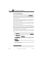
The Editor User Interface and Basic Operations
The Editor User Interface and Basic
Operations
The Editor User Interface
The editor window can be used for viewing OM, SC, DP, MSC and
HMSC diagrams.
The general Telelogic Tau user interface is described in chapter 1, User
Interface and Basic Operations.
These functions are provided:
•
The Entity Dictionary Window, which provides a name reuse facility as well as information for link endpoints.
•
A symbol menu where you select the symbols that are to be inserted.
•
A text window where you may edit text associated with symbols.
When you edit OM diagrams, three auxiliary windows are also provided:
•
The Browse & Edit Class Dialog which you use to browse amongst
and inspect and edit OM classes distributed across page and diagram boundaries.
•
The Line Details Window which allows you to inspect and edit the
various attributes of OM lines.
•
The Symbol Details Window which allows you to inspect and edit
OM symbol attributes.
When you edit DP diagrams, two of the auxiliary windows are also
available:
•
The Line Details Window which allows you to inspect and edit the
various attributes of DP lines.
•
The Symbol Details Window which allows you to inspect and edit
DP symbol attributes.
When you edit MSC diagrams this function is also available:
July 2003
Telelogic Tau 4.5 User’s Manual
,um-st1
1579
Chapter
40
•
Using Diagram Editors
An instance ruler which allows you to view the kinds of instances,
even if the instance head symbols are not currently in view.
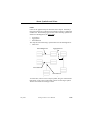
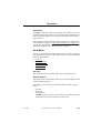
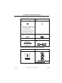
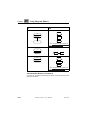
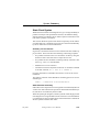
The symbol
menu
The text
window
Figure 277: The editor window showing an OM diagram (on UNIX)
1580
,um-st1
Telelogic Tau 4.5 User’s Manual
July 2003
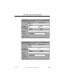
The Editor User Interface and Basic Operations
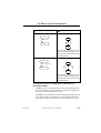
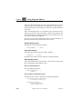
The symbol menu
The text window
Figure 278: The editor window showing an OM diagram (in Windows)
July 2003
Telelogic Tau 4.5 User’s Manual
,um-st1
1581
40
Chapter
Using Diagram Editors
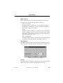
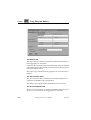
The Editor Drawing Area
The drawing area is the part of the window which displays the symbols,
lines and text that constitute a page (a diagram can contain multiple pages) or an MSC or DP diagram.
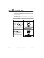
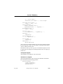
The page name
The heading
Symbols
Lines
The frame
The printout page number
Figure 279: The drawing area with an OM page displayed
1582
,um-st1
Telelogic Tau 4.5 User’s Manual
July 2003
The Editor User Interface and Basic Operations
The heading
Symbols and
lines
Figure 280: The drawing area with an MSC Diagram displayed
Drawing Area Boundaries
The drawing area is delimited by its boundaries, which correspond to
the size of the page. No objects are allowed to be placed outside these
boundaries. The drawing area uses a light background color, while the
area outside the drawing area uses a grey pattern.
Within a diagram, each page has an individual size.
The Frame
The frame always coincides with the drawing area size. It is selectable
but not editable. The frame is automatically selected with the Select All
menu choice.
It is not possible to connect any diagram symbol to the frame. The frame
only affects if the page is printed with or without a frame when printing
selected objects, or when selected symbols are copied to a metafile
(Windows only).
July 2003
Telelogic Tau 4.5 User’s Manual
,um-st1
1583
Chapter
40
Using Diagram Editors
The Heading
OM, SC and DP only: The heading contains the diagram name. The
heading is editable but cannot be moved. The editor performs a textual
syntax check on the name used in the heading, see “Diagram Name Syntax” on page 1688.
MSC and HMSC only: The heading identifies the chart type and name.
The type cannot be edited.
The Page Name
All editors except MSC and DP.
In the upper right corner, the page name and the total number of pages
in the diagram (within parentheses) are identified. The page name cannot be moved. To rename a page, use the Edit menu choice in the Pages
menu.
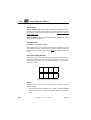
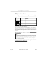
The Printout Page Number
If a diagram page is larger than the paper format that is defined, the diagram page will be split into several printout pages. In this case, page
numbers will be created. The page numbering follows a “down first,
then right” fashion.
1
3
5
7
2
4
6
8
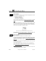
Figure 281: Page numbering in the editor
Grids
The editor uses two grids for an easy positioning of symbols, lines and
textual elements:
•
1584
,um-st1
The symbol grid has a resolution of 5 * 5 mm, except for the MSC
editor where it is 2.5 * 2.5 mm. All symbols adhere to the symbol
grid.
Telelogic Tau 4.5 User’s Manual
July 2003
The Editor User Interface and Basic Operations
•
The line and text grid has a resolution of 2.5 * 2.5 mm. All lines and
textual objects adhere to the line grid.
None of the grids can be changed.
Color on Symbols
All editors except MSC.
For each symbol type in the editor there is a preference for setting the
color of the symbol. It is only the graphical part of the symbol and not
the associated text(s) that will use the color setting. On UNIX, this setting
is only valid on screen and all symbols will use the black color when
printed on paper. In Windows, when using MSW Print the color settings
will be sent to the printer as well. See “OM/SC/HMSC/MSC/DP Editor
Preferences” on page 273 in chapter 3, The Preference Manager.
The text symbol is the same in OM, SC, DP and HMSC diagrams and
has thus only one preference.
Keyboard Accelerators
In addition to the standard keyboard accelerators, the editor features the
following:
July 2003
Accelerator
Reference to corresponding command
Ctrl+D
“Next page” on page 1586
Ctrl+U
“Previous page” on page 1586
Ctrl+T
“Symbol Details” on page 1628
<Delete>
“Clear” on page 1626
Ctrl+1
“Show Organizer” on page 15 in chapter 1, User
Interface and Basic Operations
Ctrl+2
“Connect to Text Editor” on page 1642
Telelogic Tau 4.5 User’s Manual
,um-st1
1585
Chapter
40
Using Diagram Editors
Quick-Buttons
In addition to the generic quick-buttons in all Telelogic Tau tools, the
editor tool bar contains the following quick-buttons. See also “General
Quick-Buttons” on page 24 in chapter 1, User Interface and Basic Operations.
Text window on / off
Toggle the text window between visible and hidden (see “Text Window” on page 1617).
Symbol menu on / off
Toggle the symbol menu between visible and hidden (see “Symbol
Menu” on page 1588).
Previous page
(not valid for MSC and DP)
Open previous page in flow (similar to “<Page Name>” on page 1634).
Dimmed if no previous page exists.
Next page
(not valid for MSC and DP)
Open next page in flow (similar to “<Page Name>” on page 1634).
Dimmed if no next page exists.
Toggle Scale
Toggle the scale between a scale to show the complete diagram in the
window (similar to Overview in “Set Scale” on page 1631) and a scale
of 100%. For MSCs, the scale is adjusted to fit the diagram width in the
window instead of the complete diagram.
Make space for new events
(MSC only)
Create space between two events (see “Make Space” on page 1629).
Remove space between two events
(MSC only)
Remove the unrequired space between two events.
Instance ruler on / off
(MSC only)
Toggle the instance ruler between visible and hidden (see “Instance
Ruler” on page 1632).
1586
,um-st1
Telelogic Tau 4.5 User’s Manual
July 2003
The Editor User Interface and Basic Operations
Scrolling and Scaling
You can scroll the view vertically and horizontally by using the scrollbars. The view may also be scrolled automatically when you move the
cursor beyond the current view, for example when you move an object
or add a symbol.
If you move the cursor close to the edge of the current view, the automatic scrolling is slow. If you move it further beyond, the scrolling is
quicker.
You can scale the view by specifying a scale or by zooming in and out.
To specify a scale:
1. Select Set Scale from the View menu.
2. In the dialog that will be opened, you can either:
–
Use the slider for setting the scale and then click the Scale button.
–
Click the Overview button to adjust the drawing area to the size
of the window. (This has the same effect as the Scale Overview
quick-button.)
To zoom in or out:
•
Click the quick-button for zoom in or zoom out.
Moving MSC Selection with Arrow Keys
You can move the selection using arrow keys in the MSC editor if there
is one single symbol or line selected. The selection is moved along one
instance in the vertical direction and between two instances in the horizontal direction.
In the MSC editor you are always in text editing mode, if there is a text
to edit for the currently selected symbol. To move the symbol selection,
press the arrow key one or several times in the direction you want to
move. At first, only the text cursor position might be changed. But when
the text cursor reaches the border of the text currently being edited (or
July 2003
Telelogic Tau 4.5 User’s Manual
,um-st1
1587
Chapter
40
Using Diagram Editors
if there is no text being edited), then the symbol selection will be
moved.
One shortcut is available for fast-forward moving to the next/previous
condition or instance head symbol attached to the current instance:
Shift+up or down arrow key.
Lock Files and Read-Only Mode
When you open a diagram or document file, e.g. a.ssy, a lock file
a.ssy.lck is created. If another user tries to open the same diagram or
document file before you close it, a dialog will appear informing the
other user that the file is in use. There are two choices in the dialog:
•
Open the file in read-only mode.
•
Reset the lock and open the file in read-write mode. (This alternative should only be used if the existing lock file is obsolete.)
The read-write mode is the normal editing mode. In read-only mode,
you are not allowed to make any changes to the diagram.
You will also enter read-only mode if you open a diagram file that you
do not have write permission for. The read-only mode is indicated by
the words read-only in the window title.
If you want to edit a diagram that is in read-only mode, there are two
alternative actions:
•
Change the file access rights in the file system to give you write permission for the diagram file. When that is done, you can change
from read-only mode to read-write mode with the Revert Diagram
operation.
•
Select File > Save As to save the diagram in a new file with write
permission.
Symbol Menu
The symbol menu contains the symbols that you can place into the drawing area.
On UNIX, the symbol menu is a fixed-sized, non-moveable auxiliary
window, associated with the drawing area and placed to the right of it.
Each editor window has its own symbol menu.
1588
,um-st1
Telelogic Tau 4.5 User’s Manual
July 2003
The Editor User Interface and Basic Operations
In Windows, the symbol menu is a fixed-sized, moveable window that
can be placed anywhere on the screen, not necessary within the limits
of the editor window. A single symbol menu is shared by all instances
of the editor currently running.
The symbol menu can be made invisible and visible again with a menu
choice, Window Options, or a quick-button. In Windows: When visible,
the symbol menu will always be placed on top of the editor window, if
the two windows overlap.
Basically, when you select a symbol in the symbol menu and click it
into the drawing area, it is added to the diagram. This chapter does not
describe how to work with symbols. Working with MSC symbols is described in chapter 42, Editing MSC Diagrams. See also “Working with
Symbols” on page 1835 in chapter 44, Using the SDL Editor, as working with symbols in this editor is similar to working with symbols in the
SDL Editor.
OM only: When a new class or object symbol is placed in the drawing
area, it will automatically become an endpoint if the preferences AlwaysEndpointClass and AlwaysEndpointObject, respectively, are set.
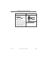
The contents of the symbol menu depends upon the type of diagram that
is displayed in the editor window, as can be seen in Figure 282. When
you switch between diagrams of different types in the editor, the symbol
menu changes accordingly.
July 2003
Telelogic Tau 4.5 User’s Manual
,um-st1
1589
Chapter
40
Using Diagram Editors
The OM
symbol menu
The SC
symbol menu
The DP
The HMSC
The MSC
symbol menu symbol menu symbol menu
Figure 282: The editor symbol menus
1590
,um-st1
Telelogic Tau 4.5 User’s Manual
July 2003
About Symbols and Lines
About Symbols and Lines
The notation used for symbols and lines in the OM Editor complies
with Static Structure (Class) diagrams defined in UML (Unified Modeling Language), version 1.3.
The notation used for symbols and lines in the SC Editor complies with
State Chart diagrams defined in UML (Unified Modeling Language),
version 1.3.
The notation used for symbols and lines in the DP Editor is based on
the notation of Deployment and Component diagrams defined in UML
(Unified Modeling Language), version 1.3.
The notation used for symbols and lines in the HMSC Editor complies
with the ITU-T Z.120 recommendation from 1996. The comment symbol and the parallel frame symbol are not supported.
The notation used for symbols and lines in the MSC Editor complies
with the ITU-T Z.120 recommendation from 1996. All MSC’96 symbols except the general ordering arrow are supported. Furthermore the
MSC Editor does not support drawing of messages to the environment
frame and message gates. Inline expressions are always global (i.e. they
cover all instances).
For short explanations of when to use different symbols, see appendix
45, Symbols and Lines – Quick Reference, on page 1987.
Symbols
Diagrams contain different types of symbols that describe the structure
of the diagram. All symbols must be placed inside the frame symbol.
Figure 282 on page 1590 identifies these symbols in the symbol menu.
You can draw symbols in color, see “Color on Symbols” on page 1585.
All symbols that are available in the symbol menu are selectable and
moveable; they can be assigned arbitrary locations by you, with the exception that symbols are normally not allowed to overlap1. SC only:
symbols can however be placed inside a state symbol, see “State Symbols” on page 1597.
1. In certain situations symbols will overlap as a consequence of automatic resizing
when new text is entered in the symbols. Such symbols can only be moved to areas where an overlap does not occur.
July 2003
Telelogic Tau 4.5 User’s Manual
,um-st1
1591
Chapter
40
Using Diagram Editors
Common Symbol
A symbol common for all the editors is:
Symbol Appearance
Symbol
Name
Text
Summary
Informal specification, global comments
Text Symbols
Text symbols contain informal text. It is not possible to connect any
lines to a text symbol.
Double-clicking on a text symbol minimizes the symbol if not already
minimized and maximizes the symbol if not already maximized.
Text symbols are typically used to add comments to diagrams or to convey system information (HMSC Editor: on a global level) that cannot
be captured using the constructs offered by the editor.
When all of the text within a text symbol is in view, the upper right corner looks like a piece of paper that has been folded. When any portion
of the text within a text symbol cannot be seen (because the text symbol
is too small), the upper right corner looks like it has been clipped.
1592
,um-st1
Telelogic Tau 4.5 User’s Manual
July 2003
About Symbols and Lines
OM Symbols and Lines
See also appendix 45, Symbols and Lines – Quick Reference, on page
1987.
Symbol Appearance
Symbol
Name
Summary
Class
Class definition
Object
Class instance
Text in Class and Object Symbols
OM symbols have one or more text compartments, which should be
filled with a textual expression. While the OM Editor does not require
that symbol text compartments should contain text, it will perform a
syntactic check on text compartments as soon as they are changed and
deselected.
The syntax rules of OM diagrams are detailed in “Object Model Syntax” on page 1687.
Note:
The OM Editor does not enforce syntax correctness in OM class and
object symbols. This means that it is possible to use any conventions
you desire for the textual contents of symbols; however, some features offered by the OM Editor will not be available, notably the
Browse & Edit Class dialog.
Syntax checking on text in general is described in greater detail under
“Textual Syntax Checks” on page 1616.
July 2003
Telelogic Tau 4.5 User’s Manual
,um-st1
1593
Chapter
40
Using Diagram Editors
Class Symbols
A class symbol is divided into three horizontal compartments. In order
from the top, the compartments are:
•
•
•
The name compartment
The attributes compartment
The operations compartment
The text in these compartments is parsed by the OM Editor and should
conform to the syntax specified in “Class Symbol Syntax” on page
1688.
In the name compartment two more extra text fields can appear. If adding text to the stereotype and properties fields in the Symbol Details
window, these texts will also be visible inside the name compartment.
These texts are not subject to syntactic checks.
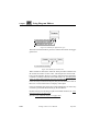
Figure 283: Class symbol with stereotype and properties texts
If you double-click a class symbol, the Browse & Edit Class dialog will
be opened (see “Browse & Edit Class Dialog” on page 1647).
Object Symbols
Used to describe an OM object, or an instance of a class.
An object symbol differs from a class symbol in that it does not contain
an operations compartment. In addition, the remaining compartments
require a somewhat different syntax, see “Object Symbol Syntax” on
page 1690.
The object symbols handles stereotype and properties texts in the same
way as the Class symbol.
If you double-click an object symbol whose name compartment includes a class name1, the Browse & Edit Class dialog will be opened
(see “Browse & Edit Class Dialog” on page 1647).
1. A class name is considered present only if the class name follows the object name
after being separated by a colon ‘:’ character.
1594
,um-st1
Telelogic Tau 4.5 User’s Manual
July 2003
About Symbols and Lines
Lines
Lines are the graphical objects that interconnect objects. Normally a
line interconnects two symbols but it could also connect a symbol with
another line. The following types of lines interconnecting symbols are
defined in OM diagrams (see Figure 284):
•
•
•
Association
Aggregation
Generalization
The only line interconnecting a symbol and a line in OM diagrams is:
•
Link Class
Generalization line
Aggregation line
Association line
Link Class line
Figure 284: Lines in OM diagrams
To insert lines, select a class or object symbol, drag one of the handles
that appear on the source symbol and connect it to the target symbol.
There is one handle for each type of line.
July 2003
Telelogic Tau 4.5 User’s Manual
,um-st1
1595
Chapter
40
Using Diagram Editors
An association line handle
An aggregation line handle
A generalization line handle
Figure 285: Handles for different line types
The Link Class line handle is placed on selected association and aggregation lines.
A Link Class line handle
Figure 286: Handle for Link Class line
When a handle is clicked, the status bar shortly describes what the handle is used for and how to draw a line. This chapter does not describe
how to work with lines. However, working with lines in the OM Editor
is similar to working with lines in the SDL Editor; see “Working with
Lines” on page 1866 in chapter 44, Using the SDL Editor.
Lines are always connected to objects; they are not allowed to exist on
their own. A line is allowed to overlap any other object.
Lines are selectable; they can be moved and reshaped by you. Some layout work is performed automatically by the OM Editor.
Double-clicking on a line brings up the Line Details window (see “Line
Details Window” on page 1652).
See also “Line Attribute Objects” on page 1609.
1596
,um-st1
Telelogic Tau 4.5 User’s Manual
July 2003
About Symbols and Lines
SC Symbols and Lines
See also appendix 45, Symbols and Lines – Quick Reference, on page
1987.
Symbol Appearance
Symbol
Name
Summary
State
State definition.
Start
Starting point of the SC.
Termination
Termination point of the SC.
Text in State Symbols
State symbols have three text compartments which should be filled with
textual expressions, but are allowed to remain empty. A syntactic check
on a text compartment is performed as soon as it is changed and deselected.
State Symbols
A state symbol contains a state section which is divided into horizontal
compartments. In order from the top, the compartments are:
•
•
The Name compartment
The Internal Activity compartment
The text in these compartments should conform to the syntax specified
in “State Symbol Syntax” on page 1692.
The state symbol may have an additional compartment with a graphic
region holding a nested SC. This is called the substate compartment and
states with this compartment are often called hierarchical states or superstates. The state will be extended with this compartment when a
symbol is placed within it. The compartment disappears when the last
symbol is removed from it.
July 2003
Telelogic Tau 4.5 User’s Manual
,um-st1
1597
Chapter
40
Using Diagram Editors
Name compartment
State_A
Internal activity compartment
entry / call Init()
Substate compartment
State_B
Figure 287: A state with its compartments
Text symbols are allowed to be placed inside the substate compartment
but will not belong to the state. Thus, it will not automatically be part of
the operations done on the state symbol, e.g. move, copy, etc.
Start Symbols
The start symbol is used to indicate where a SC starts.
Termination Symbols
The termination symbol is used to indicate where a SC terminates.
Lines
Lines are the graphical objects that interconnect objects. There is only
one kind of line interconnecting symbols in SC diagrams, a transition
line (see Figure 284):
Transition line
State_A
State_B
Figure 288: Transition line in SC diagrams
To insert lines, select a start or state symbol, drag the handle that appears on the source symbol and connect it to the target symbol.
1598
,um-st1
Telelogic Tau 4.5 User’s Manual
July 2003
About Symbols and Lines
State_A
Transition line handle
Figure 289: Handle for transition lines
When a handle is clicked, the status bar shortly describes what the handle is used for and how to draw a line. This chapter does not describe
how to work with lines. However, working with lines in the SC Editor
is similar to working with lines in the SDL Editor; see “Working with
Lines” on page 1866 in chapter 44, Using the SDL Editor.
Lines are always connected to objects; they are not allowed to exist on
their own. A line is allowed to overlap any other object.
Lines are selectable; they can be moved and reshaped by you. Some layout work is performed automatically by the SC Editor.
See also “Line Attribute Objects” on page 1609.
July 2003
Telelogic Tau 4.5 User’s Manual
,um-st1
1599
Chapter
40
Using Diagram Editors
DP Symbols and Lines
See also appendix 45, Symbols and Lines – Quick Reference, on page
1987.
.
Symbol Appearance
Symbol
Name
Summary
Node
A run-time physical object that represents a computational resource
(see [5] on page 1702).
Component
A physical, replacable part of a system that packages implementation
(see [5] on page 1702).
Thread
An OS thread, i.e. a light-weight
process. Not to be mistaken for an
OS task, i.e. a heavy-weight process.
Object
An SDL entity, i.e. a system, block
or process.
Double-clicking on a DP symbol brings up the Symbol Details window
(see “Symbol Details Window” on page 1670).
Node Symbols
For node symbols the following text attributes can be edited:
•
•
•
The name text
The stereotype text
The properties text
The name text can be edited directly in the symbol and should conform
with the syntax described in “Node Symbol Syntax” on page 1695. The
other texts can be edited in the Symbol Details window and are not subject to syntactic checks.
1600
,um-st1
Telelogic Tau 4.5 User’s Manual
July 2003
About Symbols and Lines
.
Figure 290: Node symbol with stereotype and properties texts
Component Symbols
The text attributes of component symbols are the same and follow the
same rules as those of node symbols. You can select the integration
model for a component symbol from the Symbol Details dialog box.
The syntax rules that apply are described in “Component Symbol Syntax” on page 1695.
Figure 291: Component symbol with properties text
Thread Symbols
For thread symbols only the name text is visual. From the Symbol Details dialog box, you can edit thread priority, stack size, queue size and
max signal size for a thread. The syntax rules described in “Thread
Symbol Syntax” on page 1695 are applied.
Object Symbols
Object symbols have the following text attributes:
•
•
•
•
The name text
The stereotype text
The properties text
The qualifier text
In the Symbol Details window the stereotype, properties and qualifier
texts can be added. If the stereotype text for an object symbol is process the appearance of the symbol is changed.
July 2003
Telelogic Tau 4.5 User’s Manual
,um-st1
1601
Chapter
40
Using Diagram Editors
.
Figure 292: Object with stereotype “process”
The qualifier of an object symbol is displayed in the status bar when
pointing the mouse at the symbol.
The syntax rules for the object symbol text attributes are described in
“Object Symbol Syntax” on page 1695.
Lines
Lines are graphical objects that interconnect objects. Two types of lines
are defined in DP diagrams (see Figure 293):
•
•
Association
Composite Aggregation
Association line
Composite
Aggregation line
Figure 293: Lines in DP diagrams
To insert lines, select a symbol, drag one of the handles that appear on
the source symbol and connect it to the target symbol. There is one handle for each type of line.
1602
,um-st1
Telelogic Tau 4.5 User’s Manual
July 2003
About Symbols and Lines
An association line handle
An aggregation line handle
Figure 294: Handles for different line types
When a handle is clicked, the status bar shortly describes what the handle is used for and how to draw a line. This chapter does not describe
how to work with lines. However, working with lines in the DP Editor
is similar to working with lines in the SDL Editor; see “Working with
Lines” on page 1866 in chapter 44, Using the SDL Editor.
Lines are always connected to objects; they are not allowed to exist on
their own. A line is allowed to overlap any other object.
Lines are selectable; they can be moved and reshaped by you. Some layout work is performed automatically by the DP Editor.
Double-clicking on a line brings up the Line Details window (see “Line
Details Window” on page 1667).
See also “Line Attribute Objects” on page 1609.
July 2003
Telelogic Tau 4.5 User’s Manual
,um-st1
1603
Chapter
40
Using Diagram Editors
HMSC Symbols and Lines
See also appendix 45, Symbols and Lines – Quick Reference, on page
1987.
Symbol Appearance
Symbol
Name
Summary
MSC Reference
Reference to another MSC diagram
or MSC reference expression
Condition
Expresses alternative path in an
HMSC
Connection
Point
Expresses that lines are connected at
this point
Start
Start of the HMSC road map.
End
End of the HMSC road map.
Reference Symbols
The reference symbol is used to refer to other (H)MSC’s of the MSC
document. The MSC references are objects of the type given by the references MSC.
MSC references may not only refer to a single MSC, but also to MSC
reference expressions. MSC reference expressions are textual MSC expressions constructed from the operators alt, par, seq, loop, opt, exc
and subst, and MSC references.
The text is parsed by the HMSC Editor and should conform to the syntax specified in “Reference Symbol Syntax” on page 1698.
Double-clicking on a reference symbol opens the referenced MSC diagram. Note that if a reference symbol contains more than one name, you
should place the cursor directly on one of the MSC names; otherwise an
dialog is presented, see “Navigate” on page 1644.
1604
,um-st1
Telelogic Tau 4.5 User’s Manual
July 2003
About Symbols and Lines
Condition Symbols
The condition symbol in HMSC’s can be used to indicate global system
states and impose restrictions on the MSC’s that are referenced in the
HMSC.
The text is parsed by the HMSC Editor and should conform to the syntax specified in “Condition Symbol Syntax” on page 1697.
Connection Point Symbols
The connection point symbol in HMSC’s is used to indicate that two (or
more) crossing lines are actually connected.
Start Symbols
The start symbol in HMSC’s is used to indicate where an HMSC road
map starts.
End Symbols
The end symbol in HMSC’s is used to indicate where and HMSC road
map ends.
Lines
Lines are the graphical objects that interconnect objects. There is only
one kind of line in the HMSC Editor.
To insert lines, select any1 of the symbols, drag the handle that appear
on the source symbol and connect it to the target symbol.
Line handle
Figure 295: Symbol line handle
1. This does not apply to the stop symbols, since lines can not be drawn from it,
only to it.
July 2003
Telelogic Tau 4.5 User’s Manual
,um-st1
1605
Chapter
40
Using Diagram Editors
When a handle is clicked, the status bar shortly describes how to draw
a line. This chapter does not describe how to work with lines. However,
working with lines in the HMSC Editor is similar to working with lines
in the SDL Editor; see “Working with Lines” on page 1866 in chapter
44, Using the SDL Editor.
Lines are always connected to objects; they are not allowed to exist on
their own. A line is allowed to cross (but not overlap) another line. Since
lines in HMSC’s are directed, lines always starts at the bottom of a symbol and ends on the top of a symbol.
Lines are selectable; they can be moved and reshaped by you.
1606
,um-st1
Telelogic Tau 4.5 User’s Manual
July 2003
About Symbols and Lines
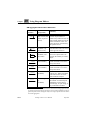
MSC Symbols and Lines
See also appendix 45, Symbols and Lines – Quick Reference, on page
1987.
Symbols are the graphical objects that build up the contents of an MSC.
Lines are the graphical objects that interconnect symbols. Lines are
available in the symbol menu and are thus handled as symbols.
Symbol
Appearance
July 2003
Symbol Name
References to Z.120
Text
Z.120
2.3
Comment
Z.120
2.3
Instance head
Z.120
4.2
Instance end
Z.120
4.2
Message
Z.120
4.3
Message-to-self
Z.120
4.3
Found message
Z.120
4.3
Lost message
Z.120
4.3
Condition
Z.120
4.6
Timera
Z.120
4.7
Separate timer setb
Z.120
4.7
Separate timer reset
Z.120
4.7
Telelogic Tau 4.5 User’s Manual
,um-st1
1607
Chapter
40
Using Diagram Editors
Symbol
Appearance
Symbol Name
References to Z.120
Separate timer consumed / timeout
Z.120
4.7
Action
Z.120
4.8
Create
Z.120
4.9
Stop
Z.120
4.10
Coregion
Z.120
5.1
MSC Reference
Z.120
5.4
Inline expression
Z.120
5.3
Inline separator
Z.120
5.3
a. The Z.120 symbols timer set and time-out are in this case merged into one symbol, the MSC Editor timer symbol.
b. A separate timer reset or timer consumed symbol is created by creating a separate timer set symbol, followed by changing its status to either reset or consumed.
Syntax Checking on Symbols and Lines
The MSC Editor checks that the symbols are positioned in the MSC in
accordance to rules governed by Z.120. Lines are always connected to
at least one symbol, they are not allowed to exist on their own. The MSC
Editor checks that lines are connected to symbols in accordance to
Z.120.
Graphical Properties of Symbols and Lines
All symbols that are available in the symbol menu are selectable and
moveable. They can be placed automatically or you may, as long as the
Z.120 syntax rules are respected, assign them arbitrary locations.
1608
,um-st1
Telelogic Tau 4.5 User’s Manual
July 2003
About Symbols and Lines
Lines are selectable; you can move them and reconnect them. Some layout work is performed automatically when a line is drawn.
Most of the symbols are not resizable; these are indicated by grayed selection squares. Other symbols may be resized; this is shown by a filled
selection square.
Textual Attributes
Textual objects are the textual attributes that are related to a symbol or
a line.
Some MSC symbols have one or multiple text attributes. A text attribute
should be filled with an MSC/PR expression (textual expression) that is
syntactically correct according to Z.120, alternatively filled with some
informal text if the MSC concept is used informally.
Text attributes related to messages and timers may be moved freely by
you. Textual objects are allowed to overlap any other objects.
Line Attribute Objects
This section applies to OM, SC and DP only.
Line attribute objects represent additional items of information associated with lines. It is not possible to create free line attribute objects that
are not associated with any line; line attributes are always associated to,
and destroyed with, their respective lines.
SC only: Each transition line has a line attribute object, the transition
label, which is pre-created by the SC Editor when you create a line. You
may ignore this attribute or fill in the textual contents, as appropriate.
The text should conform to the syntax specified in “Transition Line
Syntax” on page 1693.
OM only: Each type of line has a primary line attribute object, the name
(for associations and aggregations) or discriminator (for generalizations) attribute, which is pre-created by the OM Editor when you create
a line. You may ignore the primary attribute or fill in the textual contents, as appropriate.
DP only: Each type of line has a primary line attribute object, the protocol (for associations) or multiplicity (for aggregations) attribute,
which is pre-created by the DP Editor when you create a line. You may
ignore the primary attribute or fill in the textual contents, as appropriate.
July 2003
Telelogic Tau 4.5 User’s Manual
,um-st1
1609
Chapter
40
Using Diagram Editors
OM and DP only: A number of secondary line attribute objects can be
created for each line using the Line Details window (see “Line Details
Window” on page 1652 and “Line Details Window” on page 1667 respectively). The exact number and types of line attribute objects depends on the type of line and is summarized in tables below.
Line attribute objects have a number of common characteristics:
•
They are conceptually attached to the closest line segment of the associated line and will be moved and redrawn as appropriate whenever the line’s layout is changed1.
•
A selected textual line attribute object is indicated by a small rectangle which shrink-wraps the actual text. If the textual attribute is
editable, the text cursor will appear at the current insertion position
inside the text, and the text window will contain the text of the selected attribute object.
•
Textual line attribute objects always display their entire contents; it
is not possible to collapse them to avoid displaying large amounts
of text, as is the case with class and object symbols.
•
OM and DP only: Syntax checks are not performed on textual line
attribute objects.
•
OM and DP only: All textual line attributes except the line’s primary attribute will be destroyed if their textual contents is cleared
and the attribute is selected. To recreate a destroyed attribute, use
the Line Details window.
OM only: While most line attributes can be moved freely and are allowed to overlap other objects, some attributes, such as the association
qualifier, are restrained by graphical layout restrictions and cannot be
freely moved.
1. While the results are normally what you would prefer, it is always possible to
manually adjust the position of moveable line attributes after repositioning the
line.
1610
,um-st1
Telelogic Tau 4.5 User’s Manual
July 2003
About Symbols and Lines
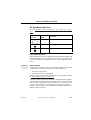
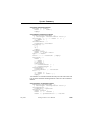
OM Line Attribute Objects
July 2003
Name and Graphical
Appearance
Line Attribute Objects
(• Primary and – Secondary)
Association
•
Name of the association
– Reverse Name
– Role Name
– Role Multiplicity
– Qualifier
– Sorted
– Ordered
– Derived Attribute
– Constraint
Aggregation
•
Name of the aggregation
– Reverse Name
– Role Name
– Role Multiplicity
– Qualifier
– Sorted
– Ordered
– Composite
Generalization
•
Discriminator of the generalization
Link Class
•
No line attributes
Telelogic Tau 4.5 User’s Manual
,um-st1
1611
Chapter
40
Using Diagram Editors
OM Aggregation/Association Attributes1
Attribute Appearance
Attribute Name
Summary
(Properties)
Name
(Pre-created, Editable, Optional
arrow)
Names a conceptual connection
between object instances.
While always bidirectional, the
name usually denotes traversal
of the association in the “forward” direction, as defined by
the optional arrow.
Reverse Name
(Editable, Optional arrow)
Allows a separate name to be
used when the link is traversed
in the opposite direction.
Qualifier
(Editable, Not
moveable)
Describes an association between two objects that is defined by the identity of a third
object.
{ordered}
Ordered
(Not editable)
The ordered attribute puts additional constraints on a one-tomany association.
{sorted}
Sorted
(Not editable)
The sorted attribute puts additional constraints on a one-tomany association.
works for
Role Name
(Editable)
Each end of an association is
called a role. While redundant,
well-named roles can sometimes facilitate analysis.
Role Multiplicity
(Editable)
Multiplicity is used to constrain
the number of related objects.
Multiplicity can be fixed, a
closed range, an open range, or
any combination of these.
name
reverse
filename
0,3-5,7+
1. While these attributes are available both for associations and aggregations, they
are much more often used for associations. The use of these attributes for aggregations depends on how sharply the analysis or design separates between association and aggregation.
1612
,um-st1
Telelogic Tau 4.5 User’s Manual
July 2003
About Symbols and Lines
Attribute Appearance
{initialized}
Attribute Name
Summary
(Properties)
Derived Attribute
(Not editable,
Not moveable)
Indicates that the association
represents redundant information, that can be calculated by
following other associations.
Constraint
(Editable)
Allows the specification of arbitrary constraints. The specified
text is automatically placed between ‘{‘ and ‘}’.
OM Aggregation Attributes
Attribute Appearance
Attribute Name
Summary
(Properties)
Composite
(Editable)
Indicates aggregation with
strong ownership.
OM Generalization Attributes
Attribute Appearance
pump type
Attribute Name
Summary
(Properties)
The discriminator describes
Discriminator
(Pre-created, Ed- which property of an object is
being abstracted by a particular
itable)
generalization relationship.
SC Line Attribute Objects
Name and Graphical
Appearance
Line Attribute Objects
Transition
•
Transition label of the transition
<<TCP/IP>>
July 2003
Telelogic Tau 4.5 User’s Manual
,um-st1
1613
Chapter
40
Using Diagram Editors
SC Transition Attributes
Attribute Appearance
event (arguments)
[guard-condition]
/actions
Attribute Name
Summary
(Properties)
Transition label Describes the transition.
(Pre-created, Ed- For a description of the syntax,
see “Transition Line Syntax” on
itable)
page 1693.
DP Line Attribute Objects
Name and Graphical
Appearance
Line Attribute Objects
(• Primary and – Secondary)
Aggregation
•
Name of the association
– Protocol
– Encoding
– Direction
Composite Aggregation
•
Multiplicity of the composite aggregation
DP Association Attributes
Attribute Appearance
Attribute Name
Summary
(Properties)
The protocol of the communicaProtocol
(Pre-created, Ed- tion path.
itable)
1614
,um-st1
name
Name
(Editable)
The name of the communication path.
{BER}
Encoding
(Editable)
The encoding of the communication path.
Direction
(Editable)
The direction of the communication path.
Telelogic Tau 4.5 User’s Manual
July 2003
Editing Text
DP Aggregation Attributes
Attribute Appearance
3,*
Attribute Name
Summary
(Properties)
Multiplicity is used to constrain
Multiplicity
(Pre-created, Ed- the number of related objects.
Multiplicity can be fixed or an
itable)
infinite number.
Editing Text
General
The drawing area is a container for different types of objects that each
may contain zero or more text compartments. In addition, the lines that
connect objects also have zero or more textual attribute objects.
The editor allows these textual objects to be edited directly in the drawing area, allowing you to see directly how the textual object resizes to
shrink-wrap the text.
To directly edit a textual object in the drawing area, simply position the
text insertion cursor at the desired position in the text. To indicate that
a textual object is being edited, a thin vertical bar designating the text
insertion cursor appears at the selected text insertion point. As soon as
you type some text, the keyboard input mode will change to text editing
mode. This is indicated by a flashing and thicker insertion bar.
In text editing mode, all accelerator keys are interpreted as input to the
text. As an example, the <Delete> key will in text editing mode delete
a character, but in non-text editing mode it will remove (Clear) an entire
symbol. This means that you can only use text editing keyboard accelerators like <Home>, <End>, <Ctrl+A> and <Ctrl+E> in text editing
mode only.
While useful for quickly editing small texts, direct editing in the drawing area suffers from some restrictions:
•
July 2003
While it is possible to position the insertion cursor in the text using
the mouse or the arrow keys, it is not possible to make any selections in the text, for deletion or replacement.
Telelogic Tau 4.5 User’s Manual
,um-st1
1615
Chapter
40
•
Using Diagram Editors
If the text becomes large enough to cross the drawing area boundary, parts of the text will no longer be visible.
To alleviate these and other limitations, the editor offers a text window
that provides a more complete set of text editing features. See “Text
Window” on page 1617 for more information. In addition, it is possible
to use an external text editor for larger amounts of texts; see “Connect
to Text Editor” on page 1642.
Regardless of whether editing takes place directly in the drawing area
or in the text window, the editor makes sure that the contents of both
displayed texts are consistent, which makes it convenient to use both
text editing mechanisms in the same diagram.
Textual Syntax Checks
Some texts in the editor are subject to syntactic checks as soon as they
are changed. Errors detected during syntax checks will be displayed in
the textual object by underlining the first characters at the position
where the first syntax error was detected.
Minimum Size of Textual Symbols
While symbols are resized automatically to fit the containing text, the
editor defines a minimum size for each symbol, ensuring that even empty symbols will be recognizable:
•
The predefined minimum width of any symbol with text is 20 mm.
•
The minimum height for symbols with text is calculated based on
the height of the symbol font.
•
The minimum height for text symbols is 10 mm.
Delayed Updating of the Drawing Area
When you edit the text in the text window, the updating of the drawing
area is at least delayed for the value of the preference
FontText*MinimumTextUpdateDelay.
If the text is large, the update delay is extended proportionally. The text
window is however always updated immediately.
In addition, any attempt to enter an illegal character will always result
in an audible warning.
1616
,um-st1
Telelogic Tau 4.5 User’s Manual
July 2003
Editing Text
Text Window
The text window works in the same way for OM, SC, DP, MSC and
HMSC diagrams. There is one text window common for OM, SC, DP
and HMSC diagrams, and a separate text window for MSC diagrams.
On UNIX, the text window is a pane of the editor window and can be re-
sized vertically.
In Windows, the text window is a resizable and moveable window that
can be placed anywhere on the screen, not necessary within the limits
of the editor window. A single text window is shared by all instances of
the editor currently running.
If you select one object in the editor window, the text window is updated
to contain the text associated with that object, but not if you select more
than one text object.
Each line (except for the last line) in the text window is terminated by a
carriage return, and may consist of any number of legal characters.
The text window provides a menu bar with two menus which are described in:
•
•
“File Menu of the Text Window” on page 1646
“Edit Menu” on page 1625
Hiding and Showing the Text Window
You can hide and show the text window with the Window Options command from the View menu, or by using a quick-button.
In Windows: When visible, the text window will always be placed on
top of the editor window.
Searching and Replacing Text in an MSC
The text window provides standardized functions for searching and replacing text in an MSC.
If all the textual objects you want to search in are not visible (i.e. instance name, instance kind, instance composition, message name and
message parameters) adjust the Diagram Options.
July 2003
Telelogic Tau 4.5 User’s Manual
,um-st1
1617
Chapter
40
Using Diagram Editors
Copying, Cutting and Pasting Text
The text window provides standardized clipboard functions for copying, cutting and pasting text between different symbols, lines and text
attributes. These functions do not interfere with the clipboard functions for cutting, copying and pasting objects.
Programmable Function Keys (UNIX only)
On UNIX, it is allowed to tie a function key to a defined text string. When
typing that defined function key, the programmed text string will be inserted at the current cursor location. You can customize your own programming of function keys.
Global X Resources
The function keys are set up as X resources. It is possible to set up both
system default and user-defined X resources, allowing you to customize
your environment. The X resources are defined in a file that is common
for all users, namely
/usr/lib/X11/app-defaults/SDT
To program the function keys, insert the following lines anywhere into
the SDT file:
/* Any suitable comment */
SDT*XmText.translations: #override \n\
<Key>F1: insert-string(“F1Text”) \n\
<Key>F2: insert-string("F2Text") \n\
<Key>F3: insert-string("F3Text") \n\
<Key>F4: insert-string("F4Text") \n\
<Key>F5: insert-string("F5Text") \n\
<Key>F6: insert-string("F6Text") \n\
<Key>F7: insert-string("F7Text") \n\
<Key>F8: insert-string("F8Text") \n\
<Key>F9: insert-string("F9Text")
/* Note the absence of \n\ on line 9 */
Note:
Omitting to define some of the function keys is permissible.
User-Defined X Resources
You can define your own function keys. This is done by defining the Xresources described above in a personal copy of the definition file and
to store that file into your home directory:
~username/SDT
1618
,um-st1
Telelogic Tau 4.5 User’s Manual
July 2003
Editing Text
Alternatively, any directory designated by environment variable
XAPPLRESDIR can be used.
Restrictions
1. Only one line for each function key can be defined. Attempting to
define more than one line into one function key may cause an unpredictable result when pressing that key.
For instance, it is not certain that the following line will produce the
expected result:
<Key>F1: insert-string("F1Line1\nLine2") \n\
2. Only the keys F1–F9 can be defined.
Changing Fonts on Text Objects
You may change the font faces and font sizes used in the textual objects
displayed by the editor. All textual objects use the same font faces and
font sizes, meaning that they cannot be changed individually and cannot
be changed during an editor session.
The font faces which are available depend on the target system on which
you are running the SDL suite.
Defining What Font to Use
To modify the desired font size and font face, you must use the Preference Manager. See chapter 4, Managing Preferences.
Textual Objects Preferences
When the setting is in effect, the SDL suite diagram editors will use the
font face names given by the preference settings
OME*ScreenFontFamily
OME*PrintFontFamily
to select font face names. Note that in this way you can select different
font names for screen and for print.
On UNIX, if you leave the Editor*FontText*ScreenFontFamily prefer-
ence setting empty, you will edit your documents using the SDT Draft
font, but print them using the font you specified with the Editor*FontText*PrintFontFamily setting.
July 2003
Telelogic Tau 4.5 User’s Manual
,um-st1
1619
Chapter
40
Using Diagram Editors
Supported Font Faces
On UNIX, the availability of font faces is determined by the version of
the X Windows server which is running. With revision 5 or higher (X11
R5), scalable fonts are supported. In that case, the available list of predefined font faces would be:
•
•
•
•
•
Times
Helvetica
Courier
SDT Draft (mapped to the Schumacher font)
Other (mapped to a user-defined font)
In Windows, the availability of font faces is determined by the TrueType fonts that are currently installed on the computer (use for instance
the Windows Control Panel to determine what is available).
Default Font Face
The default font face is Helvetica (see the preferences ScreenFontFamily and PrintFontFamily described in “OM/SC/HMSC/MSC/DP Editor
Preferences” on page 273 in chapter 3, The Preference Manager).
On UNIX, if scalable fonts are not supported, the font face will be replaced by a Schumacher font which may be used in all circumstances
(MSC only).
Default Font Size
Font sizes are described in “NameTextHeight” on page 274 and
“TextHeight” on page 275 in chapter 3, The Preference Manager.
They are used as follows:
Common Font Sizes
1620
,um-st1
Text Object
Font Size
Heading symbol
NameTextHeight
Text symbol
TextHeight
Telelogic Tau 4.5 User’s Manual
Other
July 2003
Editing Text
OM Font Sizes
Text Object
Font Size
Other
Class symbol name
NameTextHeight
Bold
Object symbol name
NameTextHeight
Bold
Stereotype text
TextHeight
Properties text
TextHeight
Italic
Text Object
Font Size
Other
State symbol name
NameTextHeight
Bold
Text Object
Font Size
Other
Symbol name
NameTextHeight
Bold
Stereotype text
TextHeight
Properties text
TextHeight
SC Font Sizes
DP Font Sizes
Italic
HMSC Font Sizes
Text Object
Font Size
Reference Symbol
TextHeight
Condition symbol
TextHeight
MSC Font Sizes
July 2003
Text Object
Font Size
All MSC special symbols
TextHeight
Telelogic Tau 4.5 User’s Manual
,um-st1
1621
Chapter
40
Using Diagram Editors
Determining Which Scalable Fonts Your Server Can Access
(UNIX only)
On UNIX, use the xlsfonts command to list installed fonts. Font names
containing 0 for width and height are scalable.
Example 296: How to determine which fonts are available –––––––––
From the OS prompt, typing:
hostname% xlsfonts | grep “\-0\-0\-“ | more
will return a list of accessible scalable fonts.
––––––––––––––––––––––––––––––––––––––––––––––––––––––––––
Scalable Fonts Under R5 Servers
To use scalable fonts under X11R5 you must normally first connect to
a font server.
Example 297: How to Start the Font Server ––––––––––––––––––––––
1. Start the font server on any local host:
hostname% fs
2. Connect the server to fs indicating which host the font server is
running on (which can be the same host that the X server is running
on):
hostname2% xset +fp tcp/<hostname>:7000
––––––––––––––––––––––––––––––––––––––––––––––––––––––––––
For further information see the X11R5 documentation or use man fs
to read the manual page describing the font server you are running.
Disabling Font Scaling (UNIX only)
On UNIX, if the fonts look poor on the screen, a possible work-around is
to disable the scaling option.
Note:
Disabling font scaling effectively disables WYSIWYG!
1622
,um-st1
Telelogic Tau 4.5 User’s Manual
July 2003
Editing Text
To do this, you should edit the SDT resource file.
1. Open the file SDT in a text editor.
2. Locate the line with the text: SDT*sdtUseScalableFonts
3. Change the line to SDT*sdtUseScalableFonts: false
4. Save the file and restart the SDL suite environment.
July 2003
Telelogic Tau 4.5 User’s Manual
,um-st1
1623
Chapter
40
Using Diagram Editors
Menu Bars
The editor menu bar provides the following menus:
•
•
•
•
•
•
•
•
File Menu
Edit Menu
View Menu
Pages Menu
Diagrams Menu
Window Menu
Tools Menu
Help Menu
The Help menu is described in “Help Menu” on page 15 in chapter 1,
User Interface and Basic Operations.
File Menu
The File menu supports the following commands on diagrams:
•
•
•
•
•
•
•
•
•
•
New
Open
Save
Save As
Save a Copy As
Save All
Close Diagram
Revert Diagram
Print
Exit
The File menu choices are described in “File Menu” on page 8 in chapter 1, User Interface and Basic Operations, except Print which is described in “The Print Dialogs in the SDL Suite and in the Organizer”
on page 308 in chapter 5, Printing Documents and Diagrams.
1624
,um-st1
Telelogic Tau 4.5 User’s Manual
July 2003
Menu Bars
Edit Menu
The Edit menu provides editing functions that you can perform on objects in a diagram, or on text in the text window. The Edit menu contains
the following menu choices:
•
•
•
•
•
•
•
•
•
•
•
•
•
•
•
•
•
Undo
Cut, Copy and Paste
Paste As
Clear
Clear Objects
Keep Objects
Expand/Collapse
Line Details
Symbol Details
Class
Drawing Size
Select All
Redirect
Connect
Status
Make Space
Decompose
Undo
This command restores the content of the drawing area to its state prior
to the most recently performed operation. Text editing operations cannot be undone.
July 2003
Editor
Operations you can undo
OM, SC, DP,
HMSC
•
•
•
•
Cut, Copy and Paste and Clear
Resizing a page
Adding/moving symbols
Drawing/reshaping/redirecting lines
OM
•
•
Editing a symbol (Symbol Details Window)
Editing a line (Line Details Window)
DP
•
•
Editing a symbol (Symbol Details Window)
Editing a line (Line Details Window)
Telelogic Tau 4.5 User’s Manual
,um-st1
1625
Chapter
40
Using Diagram Editors
Editor
Operations you can undo
OM
•
Editing a class (Browse & Edit Class Dialog)
Note: Undoing an Edit Class operation will undo
the changes in all affected diagrams.
SC
•
Expanding/collapsing symbols
HMSC
•
•
Editing a symbol
Editing a line
MSC
•
•
•
•
•
•
Cut, Copy and Paste and Clear
Undo
Redirect
Connect
Moving Objects
Adding and Removing Objects
Cut, Copy and Paste
These commands provide standardized clipboard functions for copying,
cutting and pasting objects in the drawing area or text in the text window.
You can interrupt a Paste operation by pressing <Esc>.
The MSC specific rules regarding the Paste command are described in
“Pasting in MSC Diagrams” on page 1673.
Paste As
Pastes the currently copied object (from the OM or Text Editor) as an
OM symbol or MSC object in the drawing area. The object is transformed and a link is optionally created between the copied and pasted
objects.
The Paste As dialog is opened. See “The Paste As Command” on page
448 in chapter 10, Implinks and Endpoints.
Clear
This command removes the selected objects from the drawing area, or
the selected text from the text window.
1626
,um-st1
Telelogic Tau 4.5 User’s Manual
July 2003
Menu Bars
Also see “Deleting an Object” on page 461 in chapter 10, Implinks and
Endpoints.
Clearing an instance head symbol or its instance axis line in an MSC
diagram will also remove all objects that were connected with the instance axis regardless of if they were selected or not.
•
A created instance left without “parent” is kept in the chart as static
instance.
•
Clearing an instance end reconnects the instance axis to the bottom
of the chart.
Clear Objects
This MSC command removes all objects similar to the selected objects.
For instance, select one message A object and one message B object and
invoke this command to remove all occurrences of message A and B.
To remove the empty spaces after removed objects, use Rearrange.
Keep Objects
This MSC command removes all objects of the same type as the selected objects that are not similar to the selected objects. For instance, select
one message C object and one message D object and invoke this command to remove all messages except C and D. To remove the empty
spaces after removed objects, use Rearrange.
Expand/Collapse
If a text symbol or a comment symbol is selected, this command allows
you to expand or collapse the symbol from or to its minimum size.
If an MSC diagram is selected, the Collapse command collapses the selected instance axes to give you an overview of the diagram. A complex
MSC can in this way be viewed in several decomposed MSCs. Two diagrams are created; one where the instances you have selected are collapsed into a decomposed instance and one where the behavior of the
instances you have selected are shown. You can Navigate from a decomposed instance to the referenced diagram.
If an OM class, OM instance or SC state symbol is selected, this command selects whether all compartments should be displayed or not. A
collapsed symbol will only display the name compartment (including
July 2003
Telelogic Tau 4.5 User’s Manual
,um-st1
1627
Chapter
40
Using Diagram Editors
the stereotype and properties texts for an OM symbol), which is particularly useful when referring to a symbol that is defined elsewhere.
Line Details
This OM and DP command brings up the modeless Line Details window, that is used to inspect and edit the properties of the currently selected line. If there is none or more than one selected object, the items
in the Line Details window will be dimmed.
The Line Details window and its appearance for different type of OM
lines is described in “Line Details Window” on page 1652. For DP lines
it is described in “Line Details Window” on page 1667.
Symbol Details
This OM and DP command brings up the modeless Symbol Details
window, that is used to inspect and edit the stereotype and properties
texts of the currently selected OM class or object symbol. If a DP node
or component symbol is selected the stereotype and properties texts can
be edited. For a component symbol, integration model can also be selected. For a DP thread symbol, the thread priority, stack size, queue
size and max signal size texts are editable. For a DP object symbol the
stereotype, properties and qualifier texts can be edited.
The Symbol Details window and its appearance are described in “Symbol Details Window” on page 1657 (for OM symbols) and in “Symbol
Details Window” on page 1670 (for DP symbols).
Class
This OM command brings up the modal Browse & Edit Class dialog on
the currently selected OM class or object. This dialog is used to inspect
and edit OM classes and objects over page and diagram boundaries.
The Browse & Edit Class dialog is described in detail “Browse & Edit
Class Dialog” on page 1647.
Drawing Size
Issues a dialog where the width and height can be adjusted. The values
will be saved.
1628
,um-st1
Telelogic Tau 4.5 User’s Manual
July 2003
Menu Bars
Enlarging the drawing, the current page may not fit any longer into the
paper that is defined with the Print preferences; the result may be a page
that requires multiple sheets of paper when printed.
Select All
This operation selects all objects contained within the drawing area, or
all text in the text window.
Status
This MSC command displays and possibly modifies the status of timers.
For more information see “Displaying and Modifying Status” on page
1677.
Make Space
This MSC command presents the Make Space dialog, where space for
events may be inserted.
•
The radio buttons Before selected object and After selected object
define whether space for insertion of events should be created before or after the currently selected object.
•
The Space of text field allows to specify how many events should
be possible to insert.
•
Clicking OK inserts space according to the number of events. All
objects which are found after the currently selected object are
pushed downwards.
Redirect
This OM command changes the orientation of the selected aggregation
or generalization line.
This SC command changes the orientation of the selected SC transition
line(s).
This DP command changes the orientation of the selected DP association line, if the line currently has a direction. The direction of a DP association line can be changed in the Line Details window.
July 2003
Telelogic Tau 4.5 User’s Manual
,um-st1
1629
Chapter
40
Using Diagram Editors
This MSC command changes the orientation of a selected message. The
new direction is indicated by a change in the orientation and position of
the message end and of the message parameters.
Connect
This MSC command opens a dialog that is used to connect a selected
condition or MSC reference symbol to one or multiple instances.
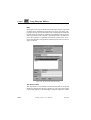
Figure 296: The Connect dialog (for a condition)
The Name field allows you to enter or change the name of the condition
or MSC reference.
The Instance List lists all possible instances that are concurrent with the
condition or MSC reference.
1630
•
Instances in the list that are selected or already connected are highlighted. Clicking an entry in the list toggles its state between highlighted and not highlighted.
•
Select Connect connects the condition or MSC reference symbol to
the instances in the instance list that are currently selected.
•
Selecting Global connects the condition or MSC reference symbol
globally to all instances in the list.
,um-st1
Telelogic Tau 4.5 User’s Manual
July 2003
Menu Bars
Decompose
This MSC command creates a new diagram of an instance axis in the
original diagram. The instance axis you decompose is marked decomposed. In the new diagram you can specify the interior of the decomposed instance.
The messages to and from the decomposed instance are displayed as
found and lost messages (see “MSC Symbols and Lines” on page 1607),
showing the communication with other instance axes. The decomposed
diagram is editable and it is displayed in the Organizer.
View Menu
The View menu provides rescaling functions and access to various options that affect the behavior of the editor. The View menu contains the
following menu choices:
•
•
•
•
•
Set Scale
Window Options
Diagram Options
Editor Options
Insert Options
Set Scale
This menu choice issues a dialog where you can adjust the scale.
Window Options
This menu choice issues a dialog where you can set the options that affect the window properties.
In the dialog, you can set if you want the following items to be displayed:
•
•
•
Tool Bar
Status Bar
Symbol Menu
On UNIX, the space allocated to the symbol menu will be reused by
the drawing area when you hide the symbol menu.
July 2003
Telelogic Tau 4.5 User’s Manual
,um-st1
1631
Chapter
40
•
Using Diagram Editors
Instance Ruler
The space allocated to the MSC instance ruler will be reused by the
drawing area when you hide the instance ruler.
•
Text Window
On UNIX, the space allocated to the text window will be reused by
the drawing area when you hide the text window.
•
Page Breaks
This option determines whether physical page breaks, with the appearance of dashed horizontal and vertical lines, should be displayed or not in the drawing area. These page breaks are defined by
the print preferences. Also, a number is shown in the bottom of each
printout page, indicating the physical page number when printed.
•
Show Grid
Click OK to apply the options in the dialog to the current window only.
Click All Windows to apply the options in the dialog to all windows
opened by the editor.
Diagram Options
This MSC command issues a dialog where you can set the options that
determines what should be displayed in the drawing area:
•
•
•
•
•
Show Instance Name
Show Instance Kind
Show Instance Composition
Show Message Name
Show Message Parameters
Click OK to apply the options to the current MSC. The diagram options
will be saved when you save the file.
1632
,um-st1
Telelogic Tau 4.5 User’s Manual
July 2003
Menu Bars
Editor Options
Opens a dialog where you can customize the behavior of the editor.
The options are controlled by toggle buttons. They are:
•
Always new Window
This option indicates whether or not a new window should be
opened when a new diagram is opened or created. The default behavior is not to open a new window.
•
Sound
This option indicates whether or not improper actions in the editor,
such as attempting to append a symbol to an illegal position, should
be brought to your attention by producing an alert sound. The default value for this option is on.
•
Show Link Endpoints
This option indicates whether endpoint markers should be displayed
for symbols having link endpoints. The default value is on.
Insert Options
This MSC command issues a dialog where spacing between symbols
may be specified. (The dimmed parts of the dialog are for future use.)
Figure 297: The Insert Options dialog
Spacing
This option allows to modify the space which is automatically inserted
between the symbols and lines when appended to the chart.
July 2003
Telelogic Tau 4.5 User’s Manual
,um-st1
1633
Chapter
40
Using Diagram Editors
There are two scales for setting the minimum horizontal distance between instance axes and the minimum vertical distance between messages.
Pages Menu
This section applies to all editors except MSC and DP.
The Pages menu holds commands that assist you in navigating among
the pages in a diagram that are currently being edited in the editor. It
also contains commands for adding, renaming and clearing pages as
well as clipboard functions for copying, cutting and pasting entire pages.
The Pages menu contains the following menu choices:
•
•
•
•
•
First
<Page Name>
Last
Add
Edit
First
This menu choice opens the first page contained in the diagram. The
first page is defined according to the order of appearance in the Edit
Page dialog.
<Page Name>
Activating the Pages menu presents up to four menu choices that consist of the names of the two pages that are sequentially immediately before and after the page being edited. If the first page of the diagram is
being edited, the next four sequential pages are shown. If the last page
of the diagram is edited, the previous four pages are shown.
Selecting one of these page names opens or restores that page in the editor. To open other pages, the Edit menu choice is used.
Last
This menu choice opens the last page of a diagram.
1634
,um-st1
Telelogic Tau 4.5 User’s Manual
July 2003
Menu Bars
Add
This menu choice is a shortcut for adding one page to the current diagram. The Add Page dialog is issued and after pressing the OK button
the new page is shown.
Edit
This menu choice allows to Add, Rename, Move up, Move down, Clear,
Cut, Copy and Paste a page. Following this menu choice, a dialog is issued.
The meaning of the various components is as follows:
Edit Pages List
Presents a list with all pages that are included in the diagram. Clicking
on a page in this list selects it and makes it the subject of the operation
to follow.
Edit Button
Clicking this button opens the selected page and displays it in an editor
window. The Edit Page dialog is closed.
Cut
Clicking this button removes the selected page from the diagram and
saves it in the clipboard buffer.
Copy
Clicking this button copies the selected page into the clipboard buffer.
Paste
Clicking this button pastes the page contained in the clipboard buffer
into the current diagram. A new dialog is issued.
The dialog allows to specify:
July 2003
•
The new name of the page. By default the page is autonumbered (the
preference is described in “AutoNumberPages” on page 273 in
chapter 3, The Preference Manager).
•
If the new page should be pasted before or after the current page.
Telelogic Tau 4.5 User’s Manual
,um-st1
1635
Chapter
40
•
Using Diagram Editors
Clicking the Paste button pastes the page according to the options
as set up in the dialog and returns control to the Edit Page dialog.
Clear
This operation clears (removes) the selected page from the diagram.
To confirm the operation, click on Clear. The editor will automatically
rename autonumbered pages.
Caution!
As stated in the dialog, Clear on a page cannot be undone.
Move up
If a diagram page is selected and you click the Move up button, the page
will be moved up.
Note:
The undo function in the Organizer and in the SDL Suite will have
no effect on page moves. It is, however, easy to undo a page move
operation by just moving the page back again.
Move down
If a diagram page is selected and you click the Move down button, the
page will be moved down.
Note:
The undo function in the Organizer and in the SDL Suite will have
no effect on page moves. It is, however, easy to undo a page move
operation by just moving the page back again.
Add
This command creates a new page which is added to the current diagram.
A new dialog is issued, in which you must insert the page name. You
can insert the new page either before or after the current page.
The dialog allows to specify:
1636
,um-st1
Telelogic Tau 4.5 User’s Manual
July 2003
Menu Bars
•
The page name. By default the page is autonumbered (this preference is described in “AutoNumberPages” on page 273 in chapter 3,
The Preference Manager).
•
Before / After current page
The new page is inserted according to the status of these radio buttons.
•
Clicking OK adds the page and returns control to the Edit Page dialog.
Rename
Click this button to open a dialog where you can rename the selected page.
Note:
Autonumbered pages cannot be renamed. The autonumbered option
must first be turned off.
•
Type in the new name of the page.
•
Click OK to rename the page. Control is returned to the Edit Page
dialog.
Autonumbered
When turning the Autonumbered option off, the editor first prompts to
confirm the removal of autonumbering on that page.
•
Click Yes to remove autonumbering on the page and then open a dialog where you can rename the page (see “Rename” on page 1637).
•
Click No to cancel the operation. The page remains autonumbered.
Turning the Autonumbered option on applies a numeric name to the selected page (1, 2, etc...). A dialog is issued where:
•
•
•
Yes auto-numbers the selected page.
All Pages auto-numbers all pages contained in the diagram.
No closes the dialog without autonumbering the pages.
Open this page first
This toggle button designates what page to be opened first when opening a diagram in the editor, if no particular page is specified.
July 2003
Telelogic Tau 4.5 User’s Manual
,um-st1
1637
Chapter
40
Using Diagram Editors
Diagrams Menu
The Diagrams menu records all diagrams that are opened by the editor.
The menu choices are:
•
•
•
•
Back
Forward
<Diagram Name>
List All
Back
Select this menu choice to browse back to the diagram that was previously displayed in the window.
Forward
Select this menu choice to browse forward to the diagram that was displayed in the window before you selected Back.
<Diagram Name>
The last edited diagram always goes to the top of the list, and subsequently moves the other diagrams down a position. A maximum of 9
open diagrams can be shown. A tenth one will be put at the top of the
list, but any subsequent opening of a diagram will only show the last 9
that have been opened.
Each item in the menu provides information about the diagram type, its
name, a slash (‘/’) followed by a page name, a hyphen and, possibly, the
file it is stored on (the file information is missing if the diagram has never been saved).
A diagram that is preceded by an asterisk (‘*’) denotes that it has been
modified during the editor session.
Note:
OM, SC, DP and HMSC diagrams are listed in the same Diagrams
menu, whereas MSC diagrams are listed only in the Diagrams menu
of the MSC Editor window.
1638
,um-st1
Telelogic Tau 4.5 User’s Manual
July 2003
Menu Bars
List All
This menu choice becomes available when a maximum of 9 open diagrams has been surpassed. When List All is selected, it provides a dialog
containing all diagrams that are currently open in the editor. Select a diagram and click Edit to display it.
Window Menu
The Window menu contains the following menu choices:
•
•
•
•
•
•
New Window
Close Window
Entity Dictionary
Info Window
<Window Name>
List All
New Window
This command opens a new editor window containing a new view on
the page, MSC or DP diagram contained in the source window from
which this menu choice was operated. The page, MSC or DP diagram
can be edited in any window.
Close Window
This option closes the open window, but, not necessarily the diagram.
If more than one editor window is opened, only the current window is
closed and not the diagram. If the last open editor window is closed, the
editor will act as if Exit has been chosen, possibly in conjunction with a
save of information.
For more information, see “Close Diagram” on page 14 in chapter 1,
User Interface and Basic Operations).
Entity Dictionary
Opens the Entity Dictionary window. See “The Entity Dictionary” on
page 434 in chapter 10, Implinks and Endpoints.
July 2003
Telelogic Tau 4.5 User’s Manual
,um-st1
1639
Chapter
40
Using Diagram Editors
Info Window
This MSC command issues a dialog as shown in Figure 298, displaying
additional information about the currently selected MSC object.
Figure 298: The Info dialog
The dialog presents:
•
A scrollable information window providing information about the
currently selected object. What information is available depends on
the selected object. See “Displaying Information About the Selected
MSC Object” on page 1678.
•
Show SDL Symbol
A button that allows, if the MSC has been automatically generated, using the SDL Simulator or SDL Validator, to obtain a traceback to the SDL source diagrams. Manually inserted symbols and
lines do not, of course, contain any trace-back information. Clicking
this button displays the SDL source symbol in an SDL Editor window. To behave properly, this feature requires that the SDL source
diagram is consistent with the generated MSC, e.g. the SDL diagram may not have been modified so that the source symbol has
been removed.
<Window Name>
If more than one editor window is open the other windows are listed
here. The behavior of this list will be similar with the diagrams list in
the “Diagrams Menu” on page 1638. The only difference is that the
menu items will not provide the diagram file information.
1640
,um-st1
Telelogic Tau 4.5 User’s Manual
July 2003
Menu Bars
List All
This menu choice will be available only if more than 9 editor windows
are open, and have the same functionality as the List All menu choice in
the Diagrams menu.
Tools Menu
The Tools menu contains the following menu choices:
•
•
•
•
•
•
•
•
•
•
•
•
•
•
•
•
•
•
•
•
Show Organizer
Link > Create
Link > Create Endpoint
Link > Traverse
Link > Link Manager
Link > Clear
Link > Clear Endpoint
Search
Spelling > Comments
Spelling > All Text
Connect to Text Editor
Show GR Reference
Create Bookmark
Convert SC to SDL
Filter
Tidy Up
Navigate
Rearrange
Generate MSC PR
Generate Input Script
All Link commands are described in “Link Commands in the Tools
Menus” on page 442 in chapter 10, Implinks and Endpoints.
Search
This menu choice allows you to search for a text in the current diagram
or document in an editor. The search can be restricted to a selected symbol type by using the Search In option menu.
You can search several diagrams and documents at the same time by using search from the Organizer, see “Search” on page 140 in chapter 2,
The Organizer.
July 2003
Telelogic Tau 4.5 User’s Manual
,um-st1
1641
Chapter
40
Using Diagram Editors
Spelling > Comments
Check the spelling of comments in the current diagram. For more information about the spelling operation, see “Spelling > Comments” on
page 144 in chapter 2, The Organizer.
Spelling > All Text
Check the spelling of all text in the current diagram. For more information about the spelling operation, see “Spelling > Comments” on page
144 in chapter 2, The Organizer.
Connect to Text Editor
This command issues an external text editor and creates a temporary file
from the currently selected text. The text can from now on only be edited in the external editor. The editor is updated every time the external
text editor saves the temporary file. When the temporary file is no longer edited, the editing control returns to the editor.
Which external text editor to use is defined by the preference
SDT*TextEditor.
Show GR Reference
This command issues a message where the graphical reference for the
currently selected object is displayed.
The syntax of the graphical references used in the editor is described in
chapter 19, SDT References.
Create Bookmark
This command creates a bookmark in the Organizer for the object you
have currently selected.
Convert SC to SDL
This SC command transforms a State Chart to an SDL process diagram.
When the conversion is done, the SDL Editor displays the newly created process diagram. A new diagram is created for every conversion. The
diagram resides in an unsaved SDL Editor buffer.
The transformation rules that are applied to the SC diagram are described in “Converting State Charts to SDL” on page 1658.
1642
,um-st1
Telelogic Tau 4.5 User’s Manual
July 2003
Menu Bars
Filter
This SC command allows you to hide uninteresting states, transitions or
signals in a statechart. All three filters are combined, making it possible
to hide stateX, transition (stateA)-signalB->(stateC) and signalZ at the
same time.
Information about hidden entities is saved in a collapsed text symbol, to
be able to recreate the entities when the filter is removed. The text in the
text symbol starts with “HiddenTransitions:”.
The dialog has the following options:
Apply filter
The current filter will be used when the dialog is closed with the OK
button.
Create new editor buffer
A new statechart is created as a new editor buffer. If this option is off,
the current statechart and editor buffer will be reused instead.
Always tidy up afterwards
The Tools>Tidy Up operation will be invoked after the filter has been
applied. If this option is off, then the Tidy Up operation will only be invoked when needed, i.e. when states or transitions that was not visible
before the operation become visible.
Create filter script text symbol
When the dialog is closed with the OK button, another dialog will appear, asking for a name for the filter. A text symbol, containing information about the current filter, will be created, starting with the text
“Filter:<newline><filter name>”. To reuse a filter saved in this way, select the text symbol before invoking the filter operation.
Tidy Up
This SC command rearranges the graphical layout of states and transitions in the State Chart. State hierarchies are flattened out, i.e. states in
states are replaced with other constructs. Positions and sizes are determined by a default layout algorithm.
July 2003
Telelogic Tau 4.5 User’s Manual
,um-st1
1643
Chapter
40
Using Diagram Editors
Navigate
The Navigate menu choice displays a (H)MSC diagram referenced by
the reference symbol or a decomposed MSC.
Since a reference symbol may contain more than one reference name
the HMSC Editor presents a dialog where you can choose reference
name.
Goto
Pressing this button will show the diagram selected in the Navigation
names list. If an (H)MSC diagram with that name is not present in the
Organizer, a dialog will be shown. If more than one (H)MSC with the
same name is present in the Organizer, an error message will be issued.
There are a number of situations when the dialog is not presented and
the referenced diagram is shown immediately:
1. There is only one reference name in the symbol.
2. The caret is positioned in a reference name. This name will be automatically selected for navigation.
For reference navigation to work correctly it is required that the expression in the symbol is syntactically correct so that the names in the symbol can be extracted. Check out “Syntax rules in Symbols” on page
1696. If you try to navigate from a symbol with incorrect syntax you
will be notified with a dialog that points out the location of the error in
the reference symbol text.
If you select a symbol that is not present in the Organizer you will be
presented with a dialog where you can create either an MSC or an
HMSC diagram.
Rearrange
This MSC command rearranges the symbols and lines in the MSC diagram to get a compact version of the same diagram. This command
might for instance be useful after having removed several signals from
the diagram.
Generate MSC PR
With this MSC and HMSC command you can save an MSC using the
Z.120 MSC/PR format. (MSC/PR can also be read by the MSC Editor,
1644
,um-st1
Telelogic Tau 4.5 User’s Manual
July 2003
Menu Bars
see “Managing MSCs” on page 1732 in chapter 42, Editing MSC Diagrams). The MSC Editor normally stores the MSCs using a binary storage format.
To generate MSC/PR:
1. Display the MSC you want to generate MSC/PR from.
2. Select Generate MSC PR from the Tools menu. A dialog is issued.
3. Specify a file where to store the generated MSC/PR. The default file
that the MSC Editor suggests consists of the name of the MSC, with
the .mpr file extension, i.e. <diagramname>.mpr
4. Make sure the Generate GR references1 radio button is turned on.
5. Click Generate.
Comment Symbols and MSC/PR
Since free comment symbols, i.e. comment symbols that are not connected to any other symbol, are not permitted in MSC/PR but can be defined using the MSC Editor, free comment symbols are converted to
text symbols in the generated MSC/PR.
Generate Input Script
This MSC command makes it possible to convert an MSC expressed in
a certain, restricted way to an input script that can be used as a script in
the SDL Simulator UI. In the Simulator UI, use the Execute>Input
Script menu choice or the execute-input-script command to execute an
input script.
How MSCs should be expressed to be able to use them as test scripts for
the SDL Simulator is described in “Simulator Test > New Simulator”
on page 154 in chapter 2, The Organizer.
Note that normally, you do not manually convert MSCs to input scripts
using this menu choice. Instead, the Organizer Tools menu choice Simulator Test > New Simulator auto-converts MSCs to input scripts when
they are needed as test cases. Manual conversion is only needed if you
1. Event oriented MSC/PR describes the MSC using the order in which the events
occur, i.e. starting with the top of the diagram and downwards, providing the
feeling of a global event order.
July 2003
Telelogic Tau 4.5 User’s Manual
,um-st1
1645
Chapter
40
Using Diagram Editors
want to stop working on the MSC level and start working on the textual
Simulator UI command level instead.
File Menu of the Text Window
The File menu provides functions that transfer text from a file to the text
window and vice-versa. The basic intention is to provide you a means
to edit larger portions of text with a more suitable text editor. Another
possibility to edit text externally is to use the Connect to Text Editor
command in the Tools menu. The available menu choices are:
•
•
Import
Export
Import
Import imports the contents of a file into the text window and inserts the
contents of the file at the current I-beam cursor position, possibly replacing selected text in the text window. A file selection dialog is issued, where the file to import text from is to be specified. The file name
filter is set to *.txt by default.
Export
Export exports the text window contents to a file. A file selection dialog
is issued, where the file to export the text to is to be specified. The file
name filter is set to *.txt by default.
1646
,um-st1
Telelogic Tau 4.5 User’s Manual
July 2003
OM Editor Specific Information
OM Editor Specific Information
Browse & Edit Class Dialog
The Browse & Edit Class dialog is opened when you select Class from
the Edit menu. The dialog allows inspection of OM diagram classes and
objects across page and diagram borders.
An object model class is defined as the union of the attributes and operations in the class and object symbols, see “Class Definition Summary”
on page 1687, and the purpose of the Browse & Edit Class dialog is to
display and ensure consistency when editing this combined information.
The Browse & Edit Class dialog is a modal dialog which is divided in
two parts. The browsing functionality is placed at the top part of the dialog, where all classes in the scope, and all occurrences of each class are
listed in two option menus. Below, in the editing part, the name of the
class, all attributes and all operations are available.
The Browse & Edit Class dialog is available when a single class or object symbol has been selected:
•
If a class symbol is selected, the Browse & Edit Class dialog will
operate on the class defined by that symbol. If the class name is
empty or contains incorrect syntax, the Browse & Edit Class dialog
will not be available.
•
If an object symbol is selected, the Browse & Edit Class dialog will
operate on the class that the object symbol instantiates. If the object
symbol does not include the name of the class it instantiates, the
Browse & Edit Class dialog will not be available.
Browse
By using the topmost part of the Browse & Edit Class dialog it is possible to browse amongst all class and object symbols within the scope.
The scope is either the entire Organizer module where the diagram is
contained, or the diagram itself if it is not contained in an Organizer
module. The module concept is described in “Module” on page 42 and
in “Module” on page 51 in chapter 2, The Organizer.
July 2003
Telelogic Tau 4.5 User’s Manual
,um-st1
1647
Chapter
40
Using Diagram Editors
Edit
By using the lower part of the Browse & Edit Class dialog it is possible
to edit the name, attributes and operations of a class. The change will
propagate into all class symbols of this class in OM diagrams within the
module where the diagram is contained. The attributes and operations
will be presented in a list. This list is parsed information from the texts
in the class symbols. If a particular text contains syntax errors, it may
lead to that attributes and operations contained in the same text do not
appear in this list.
Figure 299: The Browse & Edit Class dialog
The Scope Label
The scope label is a non-editable text field that describes the scope that
the Browse & Edit Class dialog is operating in. The scope can be either
a single OM diagram or all OM diagrams within an Organizer module.
1648
,um-st1
Telelogic Tau 4.5 User’s Manual
July 2003
OM Editor Specific Information
•
If the diagram containing the object from which the Browse & Edit
Class dialog was invoked is not part of a module in the Organizer,
the scope label contains the text “Scope: diagram <diagram
name>”.
•
If the diagram containing the object from which the Browse & Edit
Class dialog was invoked is part of a module in the Organizer, the
scope label contains the text “Scope: module <module name>”.
The Classes in Scope Option Menu
The Classes in Scope option menu contains a list of all classes within
the scope. By selecting one of the classes in this menu the corresponding symbol will be shown and selected in the drawing area.
The Show Symbol in Option Menu
One class can be represented by several class symbols. The Show Symbol in option menu lists all occurrences of the class currently selected in
the Classes in Scope option menu. The notation in the menu is <diagram-name>/<page-name>. By selecting an occurrence in this menu
the corresponding symbol will be shown and selected in the drawing area.
The Class Name Field
The name field is an editable text field that initially contains the name
of the class that is being edited.
By editing the class name field, it is possible to update all occurrences
of that class name in class and object symbols in the current scope when
the OK button is clicked.
The Attributes/Operations Buttons
The Attributes and Operations buttons select whether the attributes/operations list will contain a list of all attributes or all operations defined
for the selected class. Only one of the attributes and operations buttons
will be selected at any time.
The Attribute/Operations List
The attributes/operations list contains an alphabetically sorted list of the
attributes or operations defined for the currently selected class.
July 2003
Telelogic Tau 4.5 User’s Manual
,um-st1
1649
Chapter
40
Using Diagram Editors
The Clear Button
The clear button removes the currently selected operation or attribute
from the Attribute/Operations list.
By clearing an attribute or operation using the clear button, that attribute
or operation will be removed from all relevant class and object symbols
using the current class name in the current scope when the OK button is
clicked.
The Visibility Option Menu
The visibility option menu contains the visibility of the currently selected attribute or operation in the Attribute/Operations list, if any.
By selecting one of the predefined values in this menu and later clicking
the OK button, the visibility of the selected attribute or operation will be
updated in all relevant class symbols using the current class name in the
current scope.
The Name Field
The name field contains the name of the currently selected attribute or
operation in the Attribute/Operations list, if any.
Editing this field will change the definition of that attribute or operation
in all relevant class and object symbols using the current class name in
the current scope when the OK button is clicked.
The Parameters Field
The parameters field is an editable text field that contains the parameters of a class operation. It is only editable when an operation is selected
in the Attribute/Operations list.
Editing this field will change the definition of the selected operation in
all relevant class and object symbols using the current class name in the
current scope when the OK button is clicked.
The Type Field
The type field is an editable text field that is only editable when an attribute or an operation is selected in the Attribute/Operations list.
Depending on the current selection, the type field contains:
1650
,um-st1
Telelogic Tau 4.5 User’s Manual
July 2003
OM Editor Specific Information
•
•
If an attribute is selected, the type of that attribute, if any.
If an operation is selected, the return type of that operation.
By editing this field, the type of the selected attribute or the return type
of the selected operation and later clicking the OK button, the type of
the selected attribute or operation will be updated in all relevant class
and object symbols using the current class name in the current scope.
Note that default values for attributes cannot be inspected or changed in
the Browse & Edit Class dialog.
The OK Button
The OK button will close the Browse & Edit Class dialog and update all
appropriate class and object symbols in the diagrams in the current
scope as described for the scope label.
Note that no changes are made in the diagrams until the OK button is
clicked. This makes it possible to specify several changes in the dialog
and later disregard them by clicking the Cancel button.
The values are syntactically checked, so it is not possible to add syntax
errors to your classes by using the Browse & Edit Class dialog. Also, it
may be impossible to delete syntactically incorrect text from symbols
using the Browse & Edit Class dialog, since the Browse & Edit Class
dialog relies on information obtained by parsing the relevant symbol
text compartments.
It is possible to undo the changes made by the Browse & Edit Class operation. Note that this undo operation may affect more than one diagram.
The Cancel Button
The Cancel button will close the Browse & Edit Class dialog and discard any changes specified in the dialog. However, if the selection has
changed in the drawing area after using any of the browsing functionality, this selection will not be canceled.
All changes made in the Browse & Edit Class dialog will be lost.
July 2003
Telelogic Tau 4.5 User’s Manual
,um-st1
1651
Chapter
40
Using Diagram Editors
Line Details Window
The Line Details window is opened when you select Line Details from
the Edit menu. It is used to inspect, and edit the properties of the currently selected line. In particular, most of the line attribute objects that
are available for the different line types can only be created from the
Line Details window1.
Some line attribute objects contain editable text, and clearing that text,
whether by editing in the Line Details window or directly in the diagram, will remove the attribute.
Changes made in the Line Details window will take immediate effect
and will be shown in the drawing area. These changes can be undone
with the Undo menu command.
Unlike the Browse & Edit Class dialog, the Line Details window is
modeless and can remain open while you continue to work with the diagrams. The contents of the window will be updated to reflect the current selection. If there is none or more than one selected line, the fields
in the Line Details window will be dimmed.
The OM Editor supports four different types of lines and the contents of
the Line Details window depends on the type of the currently selected
line:
•
If an Association line is selected, all items except the Composite
button in the Line Details window will be active. See Figure 300.
•
If an Aggregation line is selected, all items in the Line Details window will be active. See Figure 301.
•
If a Generalization line is selected, only a single editable text field,
containing the generalization’s discriminator, will be available. See
Figure 302.
•
If a Link Class line is selected, all items in the Line Details window
will be dimmed.
•
If none or more than one line is selected, all items in the Line Details
window will be dimmed.
1. Once created, however, all editable textual line attribute objects can be selected
and edited directly in the diagram, without the use of the Line Details window.
1652
,um-st1
Telelogic Tau 4.5 User’s Manual
July 2003
OM Editor Specific Information
Figure 300: The Line Details window when an association line is selected
Figure 301: The Line Details window when an aggregation line is selected
July 2003
Telelogic Tau 4.5 User’s Manual
,um-st1
1653
Chapter
40
Using Diagram Editors
Figure 302: The Line Details window when a generalization line is selected
The Name Field
The Name field is an editable text field that contains the name of the selected aggregation or association.
Unlike the other text fields in the Line Details window, the line attribute
object defined by the name field is permanent and is not destroyed even
if the name field is cleared.
This field is only available when an aggregation or association line is
selected.
The Discriminator Field
The Discriminator field is an editable text field that changes the discriminator text attribute of the generalization.
This field is only available when a generalization line is selected.
The Reversed Name Field
The Reversed Name field is an editable text field that allows the specification of a reversed name for an aggregation or association.
1654
,um-st1
Telelogic Tau 4.5 User’s Manual
July 2003
OM Editor Specific Information
This field is only available when an aggregation or association line is
selected.
The Arrow Buttons
Each of these two buttons toggle an option that shows or hides the optional arrow defining the direction of the name attribute or the reversed
name attribute, respectively.
The direction and position of the arrow will be automatically calculated
from the position and size of the associated name attribute as well as the
direction of the line.
Typically it is desirable to use arrows to enhance clarity when defining
both name and reversed name fields.
These buttons are only available when an aggregation or association
line is selected.
The Role Name Fields
The Role Name fields are editable text fields that allow you to create and
edit the role attributes belonging to each end of the association or aggregation.
These fields are only available when an aggregation or association line
is selected.
The Role Multiplicity Fields
The Role Multiplicity fields are editable text fields that allow you to create and edit the multiplicity attributes of each end of an association or
aggregation.
The name field is only available when an aggregation or association line
is selected.
The Ordered Buttons
Selecting the Ordered toggle creates an uneditable text attribute containing the text “{ordered}”. Deselecting the Ordered toggle removes
this text attribute.
The ordered text attribute can be specified both in the primary and the
reverse direction.
July 2003
Telelogic Tau 4.5 User’s Manual
,um-st1
1655
Chapter
40
Using Diagram Editors
These buttons are only available when an aggregation or association
line is selected.
The Sorted Buttons
Selecting the Sorted toggle creates an uneditable text attribute containing the text “{sorted}”. Deselecting the Sorted toggle removes this text
attribute.
The sorted text attribute can be specified both in the primary and the reverse direction.
These buttons are only available when an aggregation or association
line is selected.
The Qualifiers Fields
The Qualifiers fields are editable text fields that allow you to create and
edit the qualifier fields in the forward and reverse direction respectively.
These fields are only available when an aggregation or association line
is selected.
The Derived Button
The Derived button is a toggle option that indicates whether the selected
association or aggregation should be marked as derived, i.e. crossed by
a small slanting line.
This button is only available when an association line is selected.
The Composite Button
The Composite button is a toggle option that indicates whether the selected aggregation should be marked as composite, i.e. the diamond
shape of the aggregation line should be filled.
This button is only available when an aggregation line is selected.
The Constraint Field
The Constraint field is an editable text field that allows you to create
and edit the constraint line attribute object.
This field is only available when an association or aggregation line is
selected.
1656
,um-st1
Telelogic Tau 4.5 User’s Manual
July 2003
OM Editor Specific Information
The Close Button
The Close button closes the Line Details window.
Symbol Details Window
The Symbol Details window is opened when you select Symbol Details
from the Edit menu. It is used to inspect, and edit the stereotype and
properties fields of the currently selected class or object symbol. These
two symbol attribute types can only be created from the Symbol Details
window. However, when created they can be edited directly in the diagram.
Figure 303: The Symbol Details dialog
Changes made in the Symbol Details window will take immediate effect and will be shown in the drawing area. These changes can be undone with the Undo menu command.
Unlike the Browse & Edit Class dialog, the Symbol Details window is
modeless and can remain open while you continue to work with the diagrams. The contents of the window will be updated to reflect the current selection. If multiple class or object symbols or any other symbol
or line is selected the Symbol Details window will be dimmed.
The placement of the stereotype and properties texts in the class and object symbol is described in “Class Symbols” on page 1594.
July 2003
Telelogic Tau 4.5 User’s Manual
,um-st1
1657
Chapter
40
Using Diagram Editors
SC Editor Specific Information
Converting State Charts to SDL
To convert state charts to SDL, you select Convert SC to SDL from the
Tools Menu.
Following are the transformation rules that are applied to the SC diagram:
Transformation Rules for Diagrams and Symbols
SC
SDL
SC diagram
Process diagram
“Heading”
Process “Heading”
Text symbol
Text symbol
Start symbol
Start symbol
Note:
This rule does not apply if the
start symbol belongs to a hierarchical state.
If an event is defined on the tran- Start symbol connected to ‘initial’ state symbol named SDLInit.
sition from this state
or
if more than one transition from
this state:
SDLInit
1658
,um-st1
Telelogic Tau 4.5 User’s Manual
July 2003
SC Editor Specific Information
SC
SDL
Termination symbol
Stop symbol
Note:
1. This rule does not apply if the
termination symbol belongs
to a hierarchical state.
2. If more than one transition to
the termination symbol, the
stop symbol is duplicated.
State symbol
State symbol
A
A
Hierarchical state symbol
Nothing
Substate symbol
State symbol with a comment
symbol
A
B
B
Substate of A
Transformation Rules for State Internal Activities
SC
SDL
For all transitions from A to B
Add action symbol
A
A
action*
B
B
entry/action
* See “Transformation Rules for
Actions” on page 1666
July 2003
Telelogic Tau 4.5 User’s Manual
,um-st1
1659
Chapter
40
Using Diagram Editors
SC
SDL
For all transitions from A to B
Add action symbol
A
A
exit/action
action*
B
B
* See “Transformation Rules for
Actions” on page 1666
Comment symbol
A
A
do/action
A
action
A
event/action
transition*
* See “Transformation Rules for
Transitions” on page 1660
Transformation Rules for Transitions
If actions are specified in the transition labels, insert actions last in the
generated transition.
1660
,um-st1
Telelogic Tau 4.5 User’s Manual
July 2003
SC Editor Specific Information
SC
SDL
Spontaneous transition
A
A
none
B
B
A
A
event
event
B
B
Continuous signal
A
A
[guard]
guard
B
B
Note: Priority is required if more
than one continuous signal exist
from the same state. This must be
manually added.
Enabling condition
A
A
event[guard]
event
B
guard
B
July 2003
Telelogic Tau 4.5 User’s Manual
,um-st1
1661
Chapter
40
Using Diagram Editors
SC
SDL
A
Timer with the name
“<A>_T<counter>”, where
<counter> is an integer.
after(expr)
timer <timer> := expr;
B
For all transitions to <A> add:
set (<timer>)
For this transition from <A>:
A
<timer>
B
For all other transitions from <A>
add:
reset (<timer>)
A
As above, but add an enabling
condition:
A
after(expr)[guard]
B
<timer>
guard
B
1662
,um-st1
Telelogic Tau 4.5 User’s Manual
July 2003
SC Editor Specific Information
SC
SDL
Continuous signal
A
A
when(expr)
expr
B
B
Note: Priority is required if more
than one continuous signal exist
from the same state. This must be
manually added.
Continuous signal
A
A
when(expr)[guard]
expr and guard
B
B
Note: Priority is required if more
than one continuous signal exist
from the same state. This must be
manually added.
Transformation Rules for State Internal Activities on
Hierarchical States
July 2003
•
An Entry action of a hierarchical state is always performed when
one of its substates is entered from the outside. This is applied for
any number of state boundaries crossed.
•
An Exit action of a hierarchical state is always performed when one
of its substates takes a transition to a state outside the substate region. This is applied for any number of state boundaries crossed.
Telelogic Tau 4.5 User’s Manual
,um-st1
1663
Chapter
40
Using Diagram Editors
•
An Event action of a hierarchical state is applied to all of its substates, at any nesting depth, unless a transition with the same event
exists on the substate.
•
A Do action of a hierarchical state is applied to all of its substates,
at any nesting depth.
Transformation Rules for Transitions on Hierarchical States
SC
SDL
C
A
C
B
Note:
Exactly one start state, with an
unlabeled transition, should exist
in the hierarchical state.
transition*
B
* See “Transformation Rules for
Transitions” on page 1660
B
A
B
C
Note:
An unlabeled transition should
exist out from the hierarchical
state.
1664
,um-st1
transition*
C
* See “Transformation Rules for
Transitions” on page 1660
Telelogic Tau 4.5 User’s Manual
July 2003
SC Editor Specific Information
SC
SDL
B
A
B
C
transition*
From state A
C
Note:
1. This rule applies for every
* See “Transformation Rules for
substate at any nesting depth. Transitions” on page 1660
2. Exception: This rule does not
apply if a transition with the
same trigger (event[guard])
exists on the substate.
July 2003
Telelogic Tau 4.5 User’s Manual
,um-st1
1665
Chapter
40
Using Diagram Editors
Transformation Rules for Actions
Depending of text contents:
SC
SDL
If text starts with ‘call’:
Procedure call
call proc(params)
If text starts with ‘output’:
proc(params)
Output
output sig
sig
If quoted text:
Informal task
“action”
Otherwise:
“action”
Task
a := 1
1666
,um-st1
a := 1
Telelogic Tau 4.5 User’s Manual
July 2003
DP Editor Specific Information
DP Editor Specific Information
Line Details Window
The Line Details window is opened when you select Line Details from
the Edit menu. It is used to inspect, and edit the properties of the currently selected line. In particular, most of the line attribute objects that
are available for the different line types can only be created from the
Line Details window1.
Some line attribute objects contain editable text, and clearing that text,
whether by editing in the Line Details window or directly in the diagram, will remove the attribute.
Changes made in the Line Details window will take immediate effect
and will be shown in the drawing area. These changes can be undone
with the Undo menu command.
The Line Details window is modeless and can remain open while you
continue to work with the diagrams. The contents of the window will be
updated to reflect the current selection.
The DP Editor supports two different types of lines and the contents of
the Line Details window depends on the type of the currently selected
line:
•
If an Association line is selected, the text fields for the name, protocol and encoding as well as the direction option menu in the Line
Details window will be active. See Figure 304.
•
If an Composite Aggregation line is selected, only the multiplicity
text field in the Line Details window will be active. See Figure 305.
•
If none or more than one line is selected, all items in the Line Details
window will be dimmed.
1. Once created, however, all editable textual line attribute objects can be selected
and edited directly in the diagram, without the use of the Line Details window.
July 2003
Telelogic Tau 4.5 User’s Manual
,um-st1
1667
Chapter
40
Using Diagram Editors
Figure 304: The Line Details window when an association line is selected
Figure 305: The Line Details window when an aggregation line is selected
The Name Field
The Name field is an editable text field that contains the name of the selected association.
1668
,um-st1
Telelogic Tau 4.5 User’s Manual
July 2003
DP Editor Specific Information
This field is only available when an association line is selected.
The Direction Option Menu
By selecting one of the predefined values in the direction option menu
the direction attribute of the currently selected association can be set. If
any other value than None is selected an arrow will appear at one of the
ends of the association line.
This option menu is only available when an association line is selected.
The Protocol Field
The Protocol field is an editable text field that allows you to create and
edit the protocol attribute of an association.
The protocol field is only available when an association line is selected.
For an association line the line attribute object defined by the protocol
field is permanent and is not destroyed even if the protocol field is
cleared. In this respect it differs from most of the other text fields in the
Line Details window.
The Encoding Field
The Encoding field is an editable text field that allows you to create and
edit the encoding attribute of an association.
The encoding field is only available when an association line is selected.
The Multiplicity Field
The Multiplicity field is an editable text field that allows you to create
and edit the multiplicity attribute of an aggregation.
The multiplicity field is only available when an aggregation line is selected.
For an aggregation line the line attribute object defined by the multiplicity field is permanent and is not destroyed even if the multiplicity field
is cleared. In this respect it differs from most of the other text fields in
the Line Details window.
July 2003
Telelogic Tau 4.5 User’s Manual
,um-st1
1669
Chapter
40
Using Diagram Editors
The Composite aggregate Button
The Composite aggregate button is a toggle option that indicates that
the selected aggregation is a composite aggregation, i.e. the diamond
shape of the aggregation line is filled.
This button is set automatically depending on the current selection and
is therefore never available.
The Close Button
The Close button closes the Line Details window.
Symbol Details Window
The Symbol Details window is opened when you select Symbol Details
from the Edit menu. It is used to inspect, and edit the stereotype and
properties fields of the currently selected node, component, thread or
object symbol. For the component symbol the integration model can be
selected. For the thread symbol you can edit thread priority, stack size,
queue size and max signal size. For the object symbol you can enter a
qualifier. These symbol attribute types can only be created from the
Symbol Details window. However, when created the stereotype and
properties texts can be edited directly in the diagram. All other settings
can only be inspected and edited in the Symbol Details window.
Figure 306: The Symbol Details dialog
Changes made in the Symbol Details window will take immediate effect and will be shown in the drawing area. These changes can be undone with the Undo menu command.
1670
,um-st1
Telelogic Tau 4.5 User’s Manual
July 2003
DP Editor Specific Information
The Symbol Details window is modeless and can remain open while
you continue to work with the diagrams. The contents of the window
will be updated to reflect the current selection. If multiple symbols or a
line is selected the Symbol Details window will be dimmed.
Generating a Partitioning Diagram Model
The Partitioning Diagram Model is used by the Targeting Expert as an
hierarchical overview of the entities that are to be built. Partitioning Diagram Models can be generated from Deployment Diagrams. More information about this can be found in chapter 41, The Deployment Editor, in the User’s Manual. That chapter contains guidelines for modeling Deployment Diagrams that can be used for targeting, as well as
information on the available integration models.
You generate Partitioning Diagram Models from the Organizer by selecting a Deployment diagram and then selecting “Targeting Expert” in
the pop-up menu. You can also select “Targeting Expert” from the Generate menu. If the generation is successful the Targeting Expert is
launched with the Partitioning Diagram Model as input.
Mapping Rules
Associations are ignored in Partitioning Diagram Model generation.
The stereotype “external” on a component or node symbol means that
the symbol and its sub-tree are not included when the Partitioning Diagram Model is generated. This makes it possible to model the environment that surrounds an SDL system in a deployment diagram.
Graphical Syntax Rules
In order to generate a valid Partitioning Diagram Model that can be used
by the Targeting Expert the rules listed below have to be followed:
•
•
•
•
•
•
•
July 2003
A valid diagram contains at least one node, one component and one
object, which are connected.
at least one component must belong to each node
at least one thread or one object must belong to each component
at least one object must belong to each thread
every symbol must have a name
names of nodes must be unique within the diagram
names of components must be unique within their node
Telelogic Tau 4.5 User’s Manual
,um-st1
1671
Chapter
40
•
•
•
Using Diagram Editors
names of threads must be unique within their component
each thread must be connected to exactly one component
each object must be connect to one component or one thread
Object symbols
For object symbols several text attributes have to be correct in order to
result in valid Partitioning Diagram Models.
The name of each object symbol in the diagram should be the name of
the corresponding SDL entity. Whether it is a system, block or process
should be specified by the stereotype and the qualifier text should describe how the SDL entity fits into the tree structure of the SDL system.
Figure 307: The tree structure of the system Demongame
Figure 307 shows the system Demongame. An object representing the
process Main in a deployment diagram should have the following text
attributes:
•
•
•
qualifier: Demongame/GameBlock/Main
stereotype: process
name: Main
In the same way an object representing the system Demongame should
have Demongame as qualifier text, the stereotype system and the name
Demongame.
1672
,um-st1
Telelogic Tau 4.5 User’s Manual
July 2003
MSC Editor Specific Information
MSC Editor Specific Information
Pasting in MSC Diagrams
To paste, you select Paste from the Edit Menu. The rules for Paste will
be described below.
When pasting the selection, the MSC Editor will process each individual object contained in the selection, adjust it to the grids if required and
connect it, if feasible, to the “closest” object(s) in the drawing area.
If the MSC Editor fails in pasting some of the objects contained in the
selection, the rest of the objects will nevertheless be pasted but without
an error message being displayed.
Pasting of Multiple Objects
When pasting a selection that consists of multiple objects, the MSC Editor attempts, as long as feasible, to preserve the original appearance of
the selection.
Pasting of Individual Objects
When pasting individual objects, the MSC Editor processes the objects
as follows:
•
Text
A text symbol may be pasted anywhere.
•
Comment
A comment symbol may be pasted anywhere. The line connecting
the comment symbol to another symbol is however lost when pasting.
•
Instance head / Instance axis
The instance head and its axis may be pasted anywhere.
•
Instance end and Stop
An instance end or stop may only be pasted at a location where it
overlaps an instance axis.
July 2003
Telelogic Tau 4.5 User’s Manual
,um-st1
1673
Chapter
40
•
“height”
Using Diagram Editors
Message
A message is connected to the instance axes which are closest to the
message’s base and end point, preserving the direction and “height”
of the message.
of an object
•
Message-to-self
A message-to-self is connected to the closest instance axis. The
“height” of the message is preserved.
•
Condition and MSC Reference
A condition or an MSC reference is connected to the instance it was
previously connected to (before copying it to the clipboard).
•
Timer
A timer is connected to the closest instance axis. The “height” of the
timer is preserved (see Message above).
•
Action
An action is pasted on the closest instance axis.
•
Create
The create symbol may be pasted anywhere, but only together with
the instance it is creating.
•
Coregion
A coregion is connected to the closest instance axis, to the left or
right. The “height” of the coregion is preserved (see Message
above).
Adding Symbols
Adding an Instance Head Symbol
When you add an instance head symbol, an instance axis line is drawn
that connects the symbol to the bottom of the drawing area. The instance
axis line cannot be drawn manually. It will be truncated or elongated
when you add or move an instance end or stop symbol upwards or
downwards. See “Adding an Instance End Symbol” on page 1742 in
chapter 42, Editing MSC Diagrams and “Adding a Stop Symbol” on
page 1743 in chapter 42, Editing MSC Diagrams.
1674
,um-st1
Telelogic Tau 4.5 User’s Manual
July 2003
MSC Editor Specific Information
The instance head symbol has three text fields:
–
–
–
The instance name field
The instance kind field
The decomposition field. See Figure 308.
The instance kind
The instance name
The instance decomposition
Figure 308: The meaning of the instance head text fields
The ITU recommendation Z.120 discusses several ways of using the
instance name and instance kind text fields. In the MSC Editor, the
text fields are used as follows:
–
Basically, the instance kind reflects what kind of instance is represented. That is, an identifier which reflects the name of the
corresponding SDL block/service/process/procedure; and an
optional identifier which identifies if it is a block, a service or a
process (the kind denominator).
–
The instance name reflects the current function of the instance.
–
The instance decomposition shows if the instance is in turn decomposed as a sub MSC. This text field is by default empty, but
can contain the text decomposed or decomposed as <diagram
name> to indicate that the instance is in turn decomposed. To
decompose an instance, you select Decompose from the Edit
menu.
Adding a Condition, MSC Reference or Inline Expression
Symbol
A condition or MSC reference describes either a global system state referring to all instances contained in the MSC or a state referring to a subset of instances (a non-global condition or MSC reference). The minimum subset is a single instance.
For two MSCs, the second is a continuation of the first if its initial global condition is identical to the final global condition of the first. Identifying an intermediate global condition can be used when breaking
down an MSC into two parts.
July 2003
Telelogic Tau 4.5 User’s Manual
,um-st1
1675
Chapter
40
Using Diagram Editors
By means of non-global conditions, combinations of MSCs with different sets of instances can also be defined. The continuation then refers
only to the common subset of instances.
The following general rule applies to the continuation of two MSCs
(MSC1 and MSC2, with a non-empty common set of instances).
MSC2 is a continuation of MSC1 if, for each instance which both MSCs
have in common:
•
•
•
MSC1 ends with a (non)global condition
MSC2 begins with a corresponding1 (non)global condition
Each (non)global condition of MSC2 has a corresponding (non)global condition in MSC1.
An inline expression symbol is always global and connected to all instances. The inline expression symbol is created from two inline expression symbol parts:
•
•
The inline expression symbol starts a new inline expression symbol.
The inline expression text in this symbol determines the inline expression type:
–
The keyword loop identifies a loop. Example: “LOOP <1, 5>”
means that the contents of the inline expression symbol will be
executed between one and five times.
–
The keyword opt identifies an optional part. The contents of the
inline expression symbol will either not be executed or executed
once.
–
The keyword exc identifies an exceptional part. The contents of
the inline expression symbol will either not be executed or executed once. If it is executed, then the rest of the MSC is skipped.
–
The keyword par identifies parts that are executed in parallel.
–
The keyword alt identifies alternative parts. Only one part will
be executed.
The inline expression separator symbol starts a new part in a parallel
or alternative inline expression.
1. Corresponding in this context means that both conditions refer to the same subset
of instances and both conditions agree with respect to name.
1676
,um-st1
Telelogic Tau 4.5 User’s Manual
July 2003
MSC Editor Specific Information
Displaying and Modifying Status
To display and modify status, you select Status from the Edit menu.
Timer Status
Z.120 specifies two appearances for the timer symbol, depending on
whether the timer has expired (i.e. time-out) or whether the timer is reset. The appearance of the timer is illustrated in Figure 309.
•
•
•
Timeout – A timer expires.
Reset – The timer is stopped.
Implicit reset – Assigned a new value while active.
A timer may
be consumed...
...reset
(stopped)...
or implicit reset.
Figure 309: Timer status
Separate Timer Status
Separate timer symbols has no need for an implicit reset. The timer can
be set two times in a row without an implicit reset in-between.
A separate timer
may be set...
...consumed...
or reset (stopped)
Figure 310: Separate Timer status
July 2003
Telelogic Tau 4.5 User’s Manual
,um-st1
1677
Chapter
40
Using Diagram Editors
Displaying Information About the Selected
MSC Object
To display information about a selected MSC object, you select Info
Window from the Window menu.
This opens a dialog displaying additional information about the currently selected MSC object. The information that is available depends on
what object is selected, and this is described in the table below.
Selected Object
Information Available
Instance head
•
•
•
•
Instance name
Instance kind
Composition
Creating instance
Instance end
•
Instance kind
Stop
•
Instance kind
Process create
•
•
•
•
Creating instance
Created instance
When the instance was createda
SDL Referencea
Message output
(the message output
is selected by clicking close to the message base)
•
•
•
•
Message name
Sending instance
Receiving instance
Message status =
– Sentb
– Consumedc
When the message was sent (now)a
Message parameters
SDL Referencea
•
•
•
1678
,um-st1
Telelogic Tau 4.5 User’s Manual
July 2003
MSC Editor Specific Information
Selected Object
Information Available
Message input
(the message input
is selected by clicking close to the
message end)
•
•
•
•
•
•
•
Timer
•
•
•
•
•
•
•
Separate timer
July 2003
•
•
•
Message name
Sending instance
Receiving instance
Message status=
– Sentb
– Consumedc
When the message was consumed
Message parameters
SDL Referencea
Timer name
Instance kind
Timer status=
– Reset (stopped)
– Implicit reset
– Timeout
When the message was sent (now)a
Timer value (Set)
Timer parameters
SDL Referencea
•
•
•
Timer name
Instance kind
Timer status=
– Set
– Reset (stopped)
– Timeout
When the message was consumed (now)a
Timer parameters
SDL Referencea
Action symbol
•
•
•
Instance kind
Action text
SDL Referencea
Condition
•
•
•
Condition or MSC reference name
Instances connected to the condition
SDL Referencea
Telelogic Tau 4.5 User’s Manual
,um-st1
1679
Chapter
40
Using Diagram Editors
Selected Object
Information Available
MSC Reference
symbol
•
•
Condition or MSC reference name
Instances connected to the condition
Text symbol
•
Symbol text
Comment symbol
•
Symbol text
Inline symbol
•
•
Instances connected
Operator (inline expression)
a. Only for diagrams created through a simulation.
b. A message is sent when it has been sent and received, but has not yet been consumed by the receiving instance. Typically, it is waiting in the receiving process input queue.
c. A message is consumed when it has been processed by the receiving instance.
Instance Ruler
When managing working on a long (vertically extended) MSC, the kind
of instance in the instance head may not be visible in the drawing area.
The instance ruler (illustrated in Figure 311) shows the kind of the instance heads that are not currently visible in the drawing area. It reduces
the amount of scrolling up or down when working on an MSC. The instance ruler may be shown or hidden with an option (see “Instance Ruler” on page 1632).
Figure 311: The instance ruler
1680
,um-st1
Telelogic Tau 4.5 User’s Manual
July 2003
MSC Editor Specific Information
Tracing a Simulation in a Message Sequence
Chart
This section describes the functionality behind tracing a simulation in
an MSC.
General
The MSC Editor may be used as a graphical trace tool, which features
the automatic generation of an MSC from a simulation.
•
The results of the simulation may be presented on line in an MSC
Editor window, in which each event of interest will be appended to
the chart in order to build up an MSC which reflects the history of
the simulation.
•
It is also possible to run the simulation, save the results on a simulator MSC log file and open the file from the MSC Editor.
•
The commands that start up the logging of MSC events, set up the
scope of trace, stop the logging of events, and so on, are given to the
simulator monitor. See chapter 51, Simulating a System.
Defining the Scope of Trace
First, the scope of trace should, if necessary, be set to the unit which is
currently of interest. This is done with the command Set-MSC-Trace.
The graphical trace is then started with a dedicated command from the
simulator monitor. See “Start-Interactive-MSC-Log” on page 2110 in
chapter 50, The SDL Simulator. In response to this command, the following happens:
1. In the Organizer, a reference to an MSC is added. The diagram is
assigned an unique name.
2. An instance of the MSC Editor window is activated on the newly
created MSC.
3. The current status for the simulation is presented by displaying all
SDL process instances that exist at the time when ordering the command Start-Interactive-MSC-Log.
July 2003
Telelogic Tau 4.5 User’s Manual
,um-st1
1681
Chapter
40
Using Diagram Editors
Mapping Between SDL and MSC
The mapping rules which govern how SDL events are transformed into
MSC symbols, lines and textual elements are summarized in the following table:
1682
SDL concept
MSC Concept
Signal
• Output
• Input
Message
• Sending
• Consumption
Signal to self
• Output
• Input
Message to self
• Sending
• Consumption
Timer
• Set
• Reset
• Implicit Reset
• Input
Timer
• Set
• Reset
• Implicit reseta
• Time-out
Create a process
Process Create
Stop a process
Stop
Environment
Environmentb
System
<system name>
Instance
<instance kind>
Substructure
<system name>
Instance
<instance kind>
Block
<block name>
Instance
<instance kind>
Process
<process name>
<instance number>
Instance
<instance kind>
<instance name>
State
Conditionc
Task
Actiond
Comment
Comment
,um-st1
Telelogic Tau 4.5 User’s Manual
July 2003
MSC Editor Specific Information
a. See “Implicit reset” on page 1685.
b. The system’s environment is denoted by env_1
c. The mapping is only completely valid for a condition connected to only one instance. A condition connected to several instances expresses a logical ANDcombination of the states of the processes corresponding to those instances.
d. The action symbol corresponds to a task symbol containing informal text. This
translation is, however, not supported when generating an MSC from a simulation.
Generating the MSC
When running the simulation, each SDL event of interest (in the scope
of MSC Trace) that takes place will cause the corresponding MSC symbol to be drawn in the drawing area of the MSC Editor.
Drawing Conventions
Layout
Default layouting algorithms are used. Each event causes the insertion
point to be translated downwards with one vertical spacing unit, keeping the intuitive feeling of absolute order between events. An event
could be, for instance, the output or the input of an SDL signal. However, if an output event is immediately followed by an input event, no
translation will take place.
Auto-Resizing of MSC
The MSC Editor will automatically enlarge the MSC size when the
MSC has grown so that it reaches the bottom or right of the drawing area. The MSC is enlarged according to a preference parameter.
Messages
A distinction is made between the reception and the consumption of
messages:
•
July 2003
Reception of a message: Once an SDL signal is output in the simulator, it is immediately placed into the input port of the receiving
process instance. There may, however, be other pending SDL signals in this queue, which means that the signal might not be input
immediately. Therefore, when a signal is output, it is illustrated as a
Telelogic Tau 4.5 User’s Manual
,um-st1
1683
Chapter
40
Using Diagram Editors
lost message, marked at its end with the name of the receiving instance, from the sending instance to the receiving instance.
•
Consumption of a message: When an SDL signal is input, the vertical position for the next event may have moved down in comparison to the position of the signal output. An input of a signal is illustrated by redrawing the line representing the message with its end
point connected to the new vertical position. (If an output event is
immediately followed by an input, there is no change in vertical position.)
•
In the case messages remain lost for a “long” time, this may be interpreted as some kind of erroneous behavior which requires special
attention. Messages that are never consumed indicate that some design error might have been introduced in the SDL system. It is up to
you to decide whether the time which has elapsed since a message
was sent should be considered as exceeding a reasonable value.
Create of Process
Each time an SDL process is dynamically created, a process create will
be drawn from the source instance axis, and the created instance will be
positioned according to the insert and grouping modes that is set. This
guarantees that no overlapping instance axes will take place.
The MSC Editor will automatically enlarge the MSC size when the
MSC has grown so that it reaches the bottom or right of the drawing area. The drawing area is enlarged according to the value of a preference
parameter.
Process Stop
If an instance is stopped (by a stop symbol), the space which becomes
available beneath the instance end symbol will not be reused for new instance axes.
1684
,um-st1
Telelogic Tau 4.5 User’s Manual
July 2003
MSC Editor Specific Information
Timers
•
The MSC Editor can handle four different timer statuses resulting
from a simulation:
–
–
–
–
Set
Reset (stopped)
Implicit reset
Timeout
On the MSC they are shown according the figure below:
Set
timer
Reset
timer
Implicitly
reset
timer
Consumed
timer
Figure 312: Timer status as shown on the MSC
–
Implicit reset
The implicit reset timer status is a non-Z.120 addition to the
MSC Editor. An implicitly reset timer is immediately set again
to its original parameters after reset. It is illustrated in the same
way as a reset timer, but the status information is reflected in the
Info dialog (see “Requesting Detailed Information on an Object” on page 1737).
Instances
•
The Environment Instance
All interchange of information between the SDL system and its environment is displayed by sending / receiving messages to or from
an instance with the name env_1. This instance is normally placed
at the left of the drawing area.
July 2003
Telelogic Tau 4.5 User’s Manual
,um-st1
1685
Chapter
40
•
Using Diagram Editors
The Void Instance
Graphically, in the Message Chart Editor, the concept conditional
trace (see “Scope of Trace for Generation of Message Sequence
Charts” on page 2119 in chapter 50, The SDL Simulator) is illustrated as sending or receiving messages to / from an instance with
the name Void. The purpose of the Void instance is to document that
a message exchange actually took place without focusing on the
sending / receiving instance.
•
The Instance Name and Instance Kind Text Fields
The ITU recommendation Z.120 allows several ways of using the
two text fields Instance Name and Instance Kind. This was discussed earlier in “Adding an Instance Head Symbol” on page 1741
in chapter 42, Editing MSC Diagrams.
When generating an MSC, the SDL Process Name and the internal
instance number managed by the simulator monitor are concatenated to build up one (MSC) Instance Name. The SDL diagram type
and diagram name are concatenated to build one Instance Kind.
Example 298 Instance Name and Instance Kind in Simulation Trace
Assume the simulation program contains an instance of the SDL diagram type = process with the diagram name = Demon and monitor
instance number = 2 This would be displayed as the following instance:
The Instance Kind
The instance Name
Figure 313: The use of the instance text fields in a simulation
Terminating the Trace
Having terminated the trace (either by stopping the simulation or turning the MSC trace off), you are responsible for saving the MSC(s) that
are the results of the simulation.
1686
,um-st1
Telelogic Tau 4.5 User’s Manual
July 2003
Syntax Summary
Syntax Summary
Object Model Syntax
While the intent of Object Model diagrams is to give as large flexibility
as possible to analysis and specification activities, the different editing
support facilities provided by the OM Editor requires textual data to follow certain syntactic conventions.
This section details the syntax rules that are imposed by the OM Editor
on textual data only. Graphical syntax rules are enforced automatically
by the OM Editor and are not described here.
Summary of Lexical Rules
In general, a somewhat restricted version of the lexical rules of SDL apply for names. These rules have the following noteworthy properties:
•
It is possible to break a name over more than one line by using the
underscore at the end of the line to escape the newline.
•
It is possible to have identifiers consisting entirely of numeric characters; e.g. “223” is a valid identifier.
•
Identifiers are not case sensitive.
•
Comments can be used anywhere in the texts. A comment is defined
as an SDL comment, i.e. /* this is a comment */
For more information on the SDL lexical rules, see the Z.100 recommendation.
The primary restriction is that identifiers containing spaces are not considered legal.
<name> ::= identifier as described above.
<c-string> ::= string as bounded by “ characters.
<sdl-string> ::= string delimited by ‘
(apostrophes).
Class Definition Summary
When interpreting OM diagrams, all class and object symbols within all
pages within all diagrams in a single module must be considered. A
class definition is considered to be the conceptual union of the informa-
July 2003
Telelogic Tau 4.5 User’s Manual
,um-st1
1687
Chapter
40
Using Diagram Editors
tion contained in all class symbols with the same name, as well as all
object symbols declared as instances of that class.
This means that the definition of a class can be distributed over several
symbols, pages and even diagrams. The definitions in class symbols
with the same name are then merged to obtain the complete definition
of the class; support for this is provided by the Browse & Edit Class dialog.
Thus, when defining classes, it is acceptable to have identical attributes
or operations defined several times, either in the same or different class
or object symbols. The identical definitions are simply redundant, and
do not affect the correctness of the complete class definition.
Note, however, that each unnamed class objects is considered distinct,
so that each unnamed class symbol defines its own class.
Diagram Name Syntax
Diagram names must follow certain restrictions since they are used to
identify the diagram with respect to other tools.
Diagramname ::= <name>
Page Name Syntax
Pagename ::= <name>
Each page name must be unique within its containing diagram.
Class Symbol Syntax
The textual information in class symbols is divided into five compartments of which three have their own syntax. The stereotype and properties compartments are not checked for syntax.
In the attributes and operation compartments the stereotype concept as
described in “Object Model Literature References” on page 1702 can be
used. The syntax chosen supports the single characters left/right
guillemot («») but it can also be written as two angle brackets. To type
the left/right guillemot in the text window, press <Ctrl> when you
type the left/right angle bracket.
1688
,um-st1
Telelogic Tau 4.5 User’s Manual
July 2003
Syntax Summary
Class Name Compartment Syntax
Classname ::= <name> |
<name> ‘:’ ‘:’ <name> |
<empty>
Class Attributes Compartment Syntax
ClassAttributesCompartment ::=
{ <stereotype> <classattribute> <note> }*
<stereotype> ::= ‘<’ ‘<’ <name> ‘>’ ‘>’ |
‘«’ <name> ‘»’ |
<empty>
<classattribute> ::=
<visibility> <attribute>
<visibility> ::=
‘+’ |
‘-’ |
‘#’ |
<empty>
<attribute> ::=
<name> <value> |
<name> ‘:’ <type> <value>
<type> ::= <name>
<value> ::= ‘=’ <valueitem> | <empty>
<valueitem> ::=
<name> |
‘-’ <name> |
‘+’ <name> |
<c-string> |
<sdl-string> |
‘(‘ <valueitemlist> ‘)’ |
‘{‘ <valueitemlist> ‘}’
<valueitemlist> ::=
<valueitem> |
<valueitemlist> ‘,’ <valueitem>
<note> ::=
‘{‘ <name> ‘}’ |
‘{‘ <name> ‘=’ <name> ‘}’ |
<empty>
Two attributes are considered identical if they have the same name and
type. Note that attributes defining different values are still considered
identical.
Class Operations Compartment Syntax
ClassOperationsCompartment ::=
{ <stereotype> <classoperation> <note> }*
<classoperation> ::=
<visibility> <operation>
<operation> ::=
<name> <return> |
<name> ‘(‘ ‘)’ <return> |
<name> ‘(‘ <parameterlist> ‘)’ <return>
July 2003
Telelogic Tau 4.5 User’s Manual
,um-st1
1689
Chapter
40
Using Diagram Editors
<parameterlist> ::=
parameter |
parameterlist ‘,’ parameter
<parameter> ::=
<type> |
<name> ‘:’ <type>
<return> ::=
‘:’ <name> |
<empty>
Two operations are considered identical only if the name, parameter list
and the return fields are all the same. Thus “op”, “op(a)” and “op:t” are
all unequal, while “op(a)”, “OP(A)” define the same operation.
Note however that “op” and “op()” are not considered equal, since the
OM Editor does not interpret an omitted parameter list as an empty parameter list.
Object Symbol Syntax
The textual information in object symbols is divided into four compartments of which two have their own syntax. The stereotype and properties compartments are not checked for syntax.
Object Name Compartment Syntax
Objectname ::=
<name> ‘:’ <classname> |
<name> |
<empty>
Object Attributes Compartment Syntax
ObjectAttributesCompartment ::=
{ <stereotype> <attribute> <note> }*
Text Symbol Syntax
Text symbols are not subject to any syntax rules.
Line Syntax
The current version of the OM Editor does not implement any syntax
checks on the contents of the textual attribute objects of lines.
1690
,um-st1
Telelogic Tau 4.5 User’s Manual
July 2003
Syntax Summary
State Chart Syntax
While the intent of State Chart diagrams is to give as large flexibility as
possible to analysis and specification activities, the different editing
support facilities provided by the SC Editor requires textual data to follow certain syntactic conventions.
This section details the syntax rules that are imposed by the SC Editor
on textual data only. Graphical syntax rules are enforced automatically
by the SC Editor and are not described here.
Summary of Lexical Rules
In general, a somewhat restricted version of the lexical rules of SDL apply for names. These rules have the following noteworthy properties:
•
It is possible to break a name over more than one line by using the
underscore at the end of the line to escape the new line.
•
It is possible to have identifiers consisting entirely of numeric characters; e.g. “223” is a valid identifier.
•
Identifiers are not case sensitive.
•
Comments can be used anywhere in the texts. A comment is defined
as an SDL comment, i.e. /* this is a comment */
For more information on the SDL lexical rules, see the Z.100 recommendation.
The primary restriction is that identifiers containing spaces are not considered legal.
<name> ::= identifier as described above.
State Definition Summary
UML allows some expressions in text segments to be defined by the tool
vendors. For State Charts such expressions should follow SDL/PR syntax, but this is not checked by the SC Editor.
When interpreting SC diagrams, all state symbols within all pages within all diagrams in a single module must be considered. A state definition
is considered to be the conceptual union of the information contained in
all state symbols with the same name.
July 2003
Telelogic Tau 4.5 User’s Manual
,um-st1
1691
Chapter
40
Using Diagram Editors
This means that the definition of a state can be distributed over several
symbols, pages and even diagrams. The definitions in state symbols
with the same name are then merged to obtain the complete definition
of the state.
Thus, when defining states, it is acceptable to have identical activities
defined several times, either in the same or different state symbols. The
identical definitions are simply redundant, and do not affect the correctness of the complete state definition.
Note, however, that each unnamed state object is considered distinct, so
that each unnamed state symbol defines its own state.
Diagram Name Syntax
The diagram name identifies the diagram.
<DiagramName> ::= <name>
Page Name Syntax
The page name identifies the page within a diagram.
<PageName> ::= <name>
Each page name must be unique within its containing diagram.
State Symbol Syntax
The textual information in state symbols’ state sections is divided into
three compartments with different syntax.
Name Compartment Syntax
The name identifies the state.
<NameCompartment> ::=
[<name>]
Internal Activity Compartment Syntax
Internal activities’ syntax is defined by the following grammar:
<InternalActivityCompartment> ::=
{<internal-activity>}*
<internal-activity> ::=
<event-signature>
[<guard-condition>]
1692
,um-st1
Telelogic Tau 4.5 User’s Manual
July 2003
Syntax Summary
[‘/’ <action-expr>]
|
<reserved-action-label> ‘/’ <action-expr>
<reserved-action-label> ::=
‘entry’ | ‘exit’ | ‘do’
<event-signature> ::=
<name> [<argument-list>] |
<predefined-event> ‘(’ <argument> ‘)’
<predefined-event> ::=
‘when’ | ‘after’
<argument-list> ::=
‘(’ [<argument> {‘,’ <argument>}*] ‘)’
<argument> ::=
<expression>
<guard-condition> ::=
‘[‘ <expression> ‘]’
<action-expr> ::=
<expression>
<expression> ::=
SDL/PR expression
Two events are considered identical only if the name and the argument
list are all the same. Thus “op” and “op(a)” are unequal, while “op(a)”,
“OP(A)” define the same event.
Note however that “op” and “op()” are not considered equal, since the
SC Editor does not interpret an omitted parameter list as an empty parameter list.
Text Symbol Syntax
Text symbols are not subject to any syntax rules.
Transition Line Syntax
The textual information in the transition label attribute of transition
lines is defined by the following grammar:
<TransitionLabel> ::=
[<event-signature>]
[<guard-condition>]
[<action-list>]
July 2003
Telelogic Tau 4.5 User’s Manual
,um-st1
1693
Chapter
40
Using Diagram Editors
<action-list> ::=
‘/’ <action-expr> {‘;’ <action-expr>}*
DP Syntax
While the intent of Deployment diagrams is to give as large flexibility
as possible to analysis and specification activities, the different editing
support facilities provided by the DP Editor require textual data to follow certain syntactic conventions.
This section details the syntax rules that are imposed by the DP Editor
on textual data only. Graphical syntax rules are enforced automatically
by the DP Editor and are not described here.
Summary of Lexical Rules
In general, a somewhat restricted version of the lexical rules of SDL apply for names. These rules have the following noteworthy properties:
•
It is possible to break a name over more than one line by using the
underscore at the end of the line to escape the newline.
•
It is possible to have identifiers consisting entirely of numeric characters; e.g. “223” is a valid identifier.
•
Identifiers are not case sensitive.
•
Comments can be used anywhere in the texts. A comment is defined
as an SDL comment, i.e. /* this is a comment */
For more information on the SDL lexical rules, see the Z.100 recommendation.
The primary restriction is that identifiers containing spaces are not considered legal.
<name> ::= identifier as described above.
Diagram Name Syntax
The diagram name identifies the diagram.
<DiagramName> ::= <name>
1694
,um-st1
Telelogic Tau 4.5 User’s Manual
July 2003
Syntax Summary
Node Symbol Syntax
The name identifies the node.
<NodeName> ::= <name> |
<empty>
There are no syntax checks on the stereotype and properties texts.
Component Symbol Syntax
The name identifies the component.
<ComponentName> ::= <name> |
<empty>
There are no syntax checks on the stereotype and properties texts.
Thread Symbol Syntax
The name identifies the thread.
<ThreadName> ::= <name> |
<empty>
Object Symbol Syntax
The name identifies the object.
<ObjectName> ::= <name> |
<empty>
There are no syntax checks on the stereotype, properties and qualifier
texts.
Text Symbol Syntax
Text symbols are not subject to any syntax rules.
Line Syntax
The DP Editor does not implement any syntax checks on the contents of
the textual attribute objects of lines.
July 2003
Telelogic Tau 4.5 User’s Manual
,um-st1
1695
Chapter
40
Using Diagram Editors
HMSC Syntax
While the intent of High level MSC diagrams is to give as large flexibility as possible to analysis and specification activities, the different
editing support facilities provided by the HMSC Editor requires textual
data to follow certain syntactic conventions as specified in MSC’96.
This section details the syntax rules that are imposed by the HMSC Editor on textual data only. Graphical syntax rules1 are enforced automatically by the HMSC Editor and are not described here.
Summary of Lexical Rules
The lexical elements follow MSC’96. These rules have the following
noteworthy properties:
•
An underscore followed by on or more spaces is ignored completely, e.g. A_ B denotes the same <name> as AB. This use of underline
makes it possible to split keywords over multiple lines since control
characters (e.g. newline) is treated as a space.
•
It is possible to have identifiers consisting entirely of numeric characters; e.g. “223” is a valid identifier.
•
Identifiers are not case sensitive.
•
Comments (<note> in Z.120) can be used anywhere between lexical units. A <note> is started by the characters /* outside a <note>
and terminated by the characters */ inside a <note>.
For more information on the MSC lexical rules, see the Z.120 recommendation.
Syntax rules in Symbols
The descriptions below describes what text is allowed in the different
symbols, it is not a description of the grammar in PR-form.
The grammar below informally describes the lexical units used as terminal symbols. Refer to Z.120 for a complete description.
<name> ::= identifier as described above.
<text> ::= approximately the ASCII character set.
1. No checks are made on completeness, however.
1696
,um-st1
Telelogic Tau 4.5 User’s Manual
July 2003
Syntax Summary
In the sections below each symbol will be described in the following
manner:
1. A short description of the symbol and/or its contents and purpose.
2. The symbols textual grammar
3. Possibly any semantic restriction and/or notes. Refer to Z.120 for a
complete description of the semantics that apply.
Diagram Name Syntax
The diagram name identifies the MSC to the outside world.
Diagramname ::= <name>
Diagram names must follow certain restrictions since they are used to
identify the diagram with respect to other tools.
Page Name Syntax
The page name identifies the page within a document.
<page name> ::= <name>
Each page name must be unique within its containing diagram.
Text Symbol Syntax
The text in a text symbol is an informal explanatory text.
<text text> ::= <text>
The text has no (formal) semantic and no restrictions.
Condition Symbol Syntax
Global conditions can be used to restrict how MSC’s can be composed
in High level MSC’s.
<condition name list> ::=
<condition name> { ‘,’ <condition name> }*
<condition name> ::= name
Global conditions indicate possible continuations of Message sequence
charts containing the same the same set of instances by means of condition name identification.
July 2003
Telelogic Tau 4.5 User’s Manual
,um-st1
1697
Chapter
40
Using Diagram Editors
Reference Symbol Syntax
MSC References are used to refer to other MSC’s of the MSC document.
<msc ref expr> ::=
<msc ref par expr> { ‘alt’ <msc ref par expr> }*
<msc ref par expr> ::=
<msc ref seq expr> { ‘par’ <msc ref seq expr> }*
<msc ref seq expr> ::=
<msc ref exc expr> { ‘seq’ <msc ref exc expr> }*
<msc ref exc expr> ::=
[ ‘exc’ ] <msc ref opt expr>
<msc ref opt expr> ::=
[ ‘opt’ ] <msc ref loop expr>
<msc ref loop expr> ::=
[ ‘loop’ [ <loop boundary> ] ]
{
‘empty’ |
<msc name> [ <parameter substitution> ] |
( <msc ref expr> )
}
<parameter substitution> ::=
‘subst’ <substitution list> ‘end’
<substitution list> ::=
<substitution> [ ‘;’ <substitution list> ]
<substitution> ::=
<replace message> |
<replace instance> |
<replace msc>
<replace message> ::=
[ ‘msg’ ] <message name> ‘by’ <message name>
<replace instance> ::=
[ ‘inst’ ] <instance name> ‘by’ <instance name>
<replace msc> ::=
[ ‘msc’ ]
{ ‘empty’ | <msc name> } ‘by’
{ ‘empty’ | <msc name> }
<msc name> ::= <name>
<message name> ::= <name>
<instance name> ::= <name>
1698
,um-st1
Telelogic Tau 4.5 User’s Manual
July 2003
Syntax Summary
MSC Syntax
While MSC diagrams allows the user to specify the analysis and specification activities in great detail with graphical symbols, there are also
fields that get their meaning from textual information only. The different editing support facilities provided by the MSC Editor checks textual
data to follow certain syntactic conventions as specified in MSC’96.
This section details the syntax rules that are imposed by the MSC Editor
on textual data only. Graphical syntax rules1 are enforced automatically
by the MSC Editor and are not described here.
Summary of Lexical Rules
The lexical elements follow MSC’96. They are identical to the lexical
rules for HMSC, see “Summary of Lexical Rules” on page 1696 for further information.
Syntax Rules in Symbols
The descriptions below describes what text is allowed in the different
symbols, i.e. it is not a description of the grammar in PR-form.
The grammar below informally describes the lexical units used as terminal symbols. Refer to Z.120 for a complete description.
<name> ::= identifier as described above.
<text> ::= approximately the ASCII character set.
In the sections below each symbol will be described in the following
manner:
1. A short description of the symbol and/or its contents and purpose.
2. The symbols textual grammar
3. Possibly any semantic restriction and/or notes. Refer to Z.120 for a
complete description of the semantics that apply.
Syntax Common with HMSC
All symbols that can take textual input in the HMSC are also present
(and the same) as those found in the MSC. See “Syntax rules in Symbols” on page 1696 for further information.
1. No checks are made on completeness, however.
July 2003
Telelogic Tau 4.5 User’s Manual
,um-st1
1699
Chapter
40
Using Diagram Editors
Syntax Specific for MSC
In addition to the symbols that are common HMSC symbols, the MSC
Editor supports the following symbols that contains text.
Comment Symbol Syntax
The text in a comment symbol is an informal explanatory text.
<comment text> ::= <text>
The text has no (formal) semantic and no restrictions.
Instance, Message and Timer Name syntax
The text identifies the entity
<instance name> ::= name
<message name> ::= name
<timer name>
::= name
Parameter Syntax
Both on messages and instance creations have parameters. In addition
the MSC also supports parameters on timers (currently nonstandard).
The Z.120 grammar for parameters is defined as follows:
<parameter list> ::=
<parameter name> [ ‘,’ <parameter list> ]
This grammar is neither able to allow empty parameter lists, nor to take
parameters that are generated from SDL. Furthermore, the grammar
does not allow string literals. The MSC Editor (and associated tools)
supports the following, more relaxed, grammar:
<parameter list> ::=
[ <relaxed name> { ‘,’ <relaxed name> } * ]
<relaxed name> ::=
<parameter name> [ ‘(‘ <relaxed name> ‘)’ }
<parameter name> ::=
<name> |
<character string> |
<character string 2>
The grammar of <character string 2> is the same as the grammar
for the Z.120 <character string> except that the apostrophe is regarded as the Z.120 <other character> and the double quote ‘”’ is
regarded as an <apostrophe>.
1700
,um-st1
Telelogic Tau 4.5 User’s Manual
July 2003
Syntax Summary
Instance Kind Syntax
The instance kind describes the type of the instance
<instance kind>::=
[ <kind denominator> ] <identifier>
<kind denominator> ::=
‘system’ | ‘block’ | ‘process’ | ‘service’
| <name>
<identifier> ::= [ <qualifier> ] <name>
<qualifier> ::= ‘<<’ <text> ‘>>’
Decomposition Syntax
This text is present if the instance is decomposed and describes the
name of the diagram that explains the decomposed instance in greater
detail.
<decomposition> ::=
‘decomposed’ [ <substructure reference> ]
<substructure referrence> ::=
‘as’ <message sequence chart name>
Inline Heading Syntax
This is the syntax for the text area in the inline expressions symbols.
<inline heading> ::=
‘alt’ |
‘par’ |
‘exc’ |
‘opt’ |
‘loop’ [<loop boundary>]
<loop boundary> ::=
‘<’ <inf natural> [ ‘,’ <inf natural> ] ‘>’
<inf natural>
::= ‘inf’ | <natural name>
<natural name> ::= {0|1|2|3|4|5|6|7|8|9}+
July 2003
Telelogic Tau 4.5 User’s Manual
,um-st1
1701
Chapter
40
Using Diagram Editors
Literature References
Object Model Literature References
There is a growing number of publications devoted to object modeling
techniques. The following two sources have been selected as defining
the Object Model supported by the OM Editor:
[5] OMG Unified Modeling Language, version 1.3, June 1999
(document ad/99-06-08) Final Draft
Object Management Group
ftp://ftp.omg.org/pub/docs/ad/
[6] Object Oriented Modeling and Design
Rumbaugh, Blaha, Premerlani, Eddy, Lorensen
Prentice-Hall (1991)
ISBN 0-13-630054-5
State Chart Literature References
There is a growing number of publications devoted to state chart techniques. The following source has been selected as defining the State
Chart supported by the SC Editor:
[7] Unified Modeling Language, version 1.1, Sept. 1997
UML Semantics (document ad/97-08-04)
UML Notation Guide (document ad/97-08-05)
Object Management Group
ftp://ftp.omg.org/pub/docs/ad/
[8] Unified Modeling Language, version 1.0, January 1997
UML Semantics (document ad/97-01-03)
UML Notation Guide (document ad/97-01-09)
Object Management Group
ftp://ftp.omg.org/pub/docs/ad/
1702
,um-st1
Telelogic Tau 4.5 User’s Manual
July 2003
Literature References
MSC‘96 Literature References
[9] Z.120 (1996).
Message Sequence Chart (MSC).
ITU-T, Geneva, April 1996
[10] Message Sequence Chart
Syntax and Sematics
M.A. Reniers, Eindhoven University of Technology, 1999
IPA Dissertation Series 1999 - 7
[11] Object-Oriented Software Engineering
– A Use Case Driven Approach.
I. Jacobson.
Addison-Wesley, 1992
[12] Tutorial on Message Sequence Charts (MSC’96)
Ekkart Rudolph, Jens Grabowski, and Peter Graubman
UML Literature References
[13] The Unified Modeling Language User Guide
Grady Booch, Ivar Jacobson, James Rumbaugh.
Addison-Wesley, 1998
[14] The Unified Modeling Language Reference Manual
James Rumbaugh, Ivar Jacobson, Grady Booch.
Addison-Wesley, 1998
[15] The Unified Software Development Process
Ivar Jacobson, James Rumbaugh, Grady Booch.
Addison-Wesley, 1999
July 2003
Telelogic Tau 4.5 User’s Manual
,um-st1
1703
Chapter
40
1704
,um-st1
Using Diagram Editors
Telelogic Tau 4.5 User’s Manual
July 2003