1
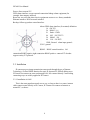
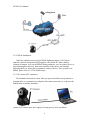
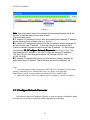
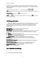
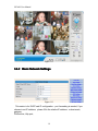
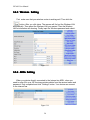
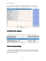
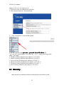
IPCAM User Manual
Wireless/Wired Network Camera
Night Vision & Remote Operation
User Manual
1
IPCAM User Manual
Thank you for buying our IP camera.
This Series Products are designed and equipped for network video surveillance
system, including wired IP bullet camera, wireless IP bullet camera, IP IR dome
camera, IP IR waterproof camera etc. We adopt high performance chip to ensure high
quality media processor which processes audio and video collection, compression and
transmission. Standard MJPEG compression format ensures clear and streaming video
performance. It enables users to view via IE browser, centre management software
client software;
AJ series products are applicable for big, medium-sized and small enterprises, chain
store, factory, home and all kinds of spots where remote network video transmission
and control supposed to be installed, They are easy to install and operate. Before the
installation of the IP camera, please check if your product accessories in
the package are complete
Product Components and Features:
IP camera ---------------------------------------------------------------------------------1 PC
Bracket(optional)------------------------------------------------------------------- -1 PC
Power adapter ----------------------------------------------------------------------------1 PC
Warranty card-----------------------------------------------------------------------------1 PC
CD------------------------------------------------------------------------------------------1 PC
Table of CONTENTS
1. General Introduction ...........................................................................................4
1.1. Product Specifications ................................................................................. ...5
1.2. Applications ................................................................................................ ....5
1.3. System Requirements ......................................................................................5
2. Interface & Installation ................................................................................. .....6
2.1. Interface ..........................................................................................................7
2.2. Installation .......................................................................................................8
2.2.1. Installation in LAN .......................................................................................8
2.2.2. PPPoE Installation ........................................................................................9
2.2.3. IP Camera & PC connection .........................................................................9
3. IE Browse to IP Camera..................................................................... ...............10
3.1. Use IP Finder Software.................................................................................. .11
2
IPCAM User Manual
3.1.1. Configure Network Parameter .....................................................................12
3.2. Logging and Active X Installation...................................................................14
3.3. Main Operation Interface.................................................................................16
3.4. Operator Operation .........................................................................................17
3.4.1. Multi-Device Settings....................................................................... ...........18
3.4.2. Basic Network Settings......................................................................... .......20
3.4.3. Wireless Settings................................................................. .........................21
3.4.4. ADSL Settings.............................................................................. ...............21
3.4.5. DDNS Settings.................................................... .........................................22
3.4.6. E-mail and FTP Services Settings.................................................... ............22
3.4.7. Alarm Services Settings ...............................................................................23
3.4.8. Reset//Firmware Upgrade Settings...............................................................24
3.4.9. Restore Factory Settings ..............................................................................24
3.4.10. Reboot Equipment Settings..........................................................................24
4. Others ..................................................................................................................25
4.1. Port Forwarding Settings in Router...................................................................25
4.2 Warranty ............................................................................................................26
3
IPCAM User Manual
General Introduction
IP Camera is a new generation product with the combination of analog camera &
IP video technology. Despite all functions which analog cameras have, IP camera can
compress and encrypt video and audio signal then send it to remote terminals through
internet with its built-in processor and web server. With its IP address, users can use
standard PC IE browser to visit IP camera, real time monitor targets, manage and store
video or image, PTZ control also is available through network.
As a new member in camera family, IP camera shares the same operation function
with the analog camera, such as, auto white balance, auto shutter speed, AGC, auto
backlight compensation etc. On the other hand, IP camera supports remote access
through internet, and support multi-user visit, some IP cameras are able to extend to
both analog and digital signal.
The core of F series IP cameras is 32Bit RSIC, adopts standard MJPEG
compression format, camera sensor is CMOS, support auto white balance and
backlight balance, support IE, cell phone browser,centralized monitor interface
management. In general, according to the function of audio simplex & duplex,
infrared, wired, wireless, POE, PZT, local storage, it has hundreds of products, to
meet requirements of high, middle, low ranks of users.
4
IPCAM User Manual
1.1. Product Specifications
*- Adopt high Performance, strong function media processor 32Bit RSIC
*- High sensor CMOS
*-Adopt optimized MJPEG video compression algorithm, realize high-definition images
transmission in narrow bandwidth;
*-Maximum support 15 users viewing at the same time, no limit for users if using
Forwarder
Server function;
*- Built in Web Server,it is convenient for users to use standard browse to realize the
real time monitoring and setting administration;
*-Support WIFI:802.11b/g wireless networking;
*-Support remote system update;
*-Support DDNS analysis, support LAN & Internet (ADSL、Cable Modem)
*-Support variety of network protocol: TCP/IP, UDP, SMTP, PPPoE, Dynamic DNS,
DNS Client, SNTP, BOOTP, DHCP, FTP, SNMP, WIFI/802. 11b/g
*-Parts of modes products support one/ two way audio talkback;
*-Support Motion Detection alarm function (set area & sensitivity);
*-Support image snap
*-Abnormal automatic recovery function,if Network Interruption can auto connection
*-Dynamic alarm function, set alarm period.
1.2. Applications
The series products usually are ideal for big department, supermarket, home,
factory, workshop etc.
1.3. System Requirements
Minimum Hardware Configuration
5
IPCAM User Manual
CPU: Pentium 1.6 GHz
Memory: 256MB
Audio card: need audio monitor, two way talkback essential
Hard Disk : if it need video image,no less favorable than 40G
Operation System: 32 bit simple/ English Windows2000、WindowsXP、
Windows2003、Windows Vista & 64 bit simple Chinese/English Windows2003、
Windows XP、Windows Vista etc.
Software environment
IE 5.0 or above version
DirectX8.0 or above version
TCP/IP network protocol
2. Interface & Installation
There are two kinds of AJ series IP camera interfaces: one is body guard interface,
the other is the extend line interface, set two representative products as examples, to
give explanation:
*Non-extended line IP Camera icon
*Extended line IP Camera icon
6
IPCAM User Manual
2.1. Interface
*Non-extended line IP Camera Tailgate
Power Supply Light: constant on after power up
Network light: constant sparkle after power up data transmission.
Ethernet interface: RJ-45 interface.
I/O interface: 1 router alarm input, accept 3, 4 two terminals (input terminal grounding,
low level effective trigger); 1 router TTL control input, connect 1,2 two
terminals (1,2 terminals short connections).
Power input interface: connect direct current 5V Power
*Extension line interface definition icon:
7
IPCAM User Manual
Power: direct current 12V.
GPIO alarm interface: accept external connection linkage alarm equipment (for
example: door magnet, infrared)
Reset line: two reset line short circuit, equipments restore to ex- factory standards.
Ethernet interface: RJ-45 network interface.
Backup: follow-up product extend interface.
About GPIO alarm interface (S terminal) definition:
1# +DC12V
2# RS485(A)
3# Earth(GND)
4# IO2 (OUT PUT)
5# RS485 (B)
6#
IO1 (IN PUT)
GND: Ground,alarm input ground ,
RS485 ground
RS485: RS485 control interface,left
connection RS485 negative right connection RS485 positive. connect P/T decoder,
support variety P/T protocol.
2.2. Installation
IP camera process image transmission on network through the use of Internet
Technology, it offers DDNS function for static IP, dynamic IP, PPPoE dialing users.
IP Camera can connect to outer net through LAN, also connect directly.3 networking
connecting ways are widely applied in IP Camera:
2.2.1. Installation in LAN.
This is the most popular network access way, as long as there is a router, internet
cable connect router directly to IP Camera, IP Camera can connect to Internet as
normal PC, as shows:
8
IPCAM User Manual
2.2.2. PPPoE Installation
Under the condition, users need set PPPoE dialing parameter on IP Camera:
input the username and password ISP supplier’ offer permit IP Camera dialing
connects to Internet. As to set the PPPoE dialing parameter, you can connect device to
network through the first way, then write parameter to the device, also through
following third way, direct process parameter written to device. The way how to set
PPPoE, please refer to 3.4.5.for detailed steps
2.2.3. IP Camera & PC connection
This method is not used too often, when you process machine write parameter or
program shift, we recommend you adopt the first connect network way, to process the
modification of machine parameter.
connect to IP camera (note: don’t apply for wrong power), after one minute
9
IPCAM User Manual
modification of IP camera, video could be connected by internet cable to IP camera;
under the normal condition, yellow light is on, green light flickers, now physical
connection of IP camera finish at this time (in order to connect successfully, we
advise to set camera IP as the stable IP at the same net range of PC in LAN , how to
set, please refer to 8 frequent questions answer).
3. IE Browse to IP Camera
After IP camera connects to PC LAN through router, you can operate on IP
camera via PC, first please run the relative software in the CD kit
3.1. Use IP Finder Software
Open the disk, double click
and appear the following interface:
icon (the IP Finder software),
Click Next
Next, complete the installation
10
IPCAM User Manual
Note
Note: Before using the product installation, please just use IPCAM standard
power adapter. The use of non-certified power adapter may damage the IPCAM.
IPCAM should only be installed in the indoor environment
After you finished install the IP Finder software, You will finder that
icon in your computer program. double click
run.
icon. The IP Finder is
Figure3.1
If the internet cable power connect is correct, after click
button it
appears device styles, name, and IP address in the list, (if it doesn’t appear, please
confirm power & internet cable work normally).
Figure3.2
11
IPCAM User Manual
Figure3.3
Note
Note: After click search button the software will automatically search for all the
devices’ IP address within a local area network..
There are three cases:
1 IP cameras’ IP address not found. After click search button devices’ IP address
did not showing in the software’s list: e.g. Figure3.1
2 IP camera’s IP address being found, but the IP Camera’s network segment not
as same as the local IP address’. In that way,first you should change the IP
Camera’s network segment as same as the local IP address’. You can change
this following 3.1.1 Configure Network Parameter e.g. Figure3.4(e.g. The
local computer’s IP address is :192.168.0.15.But the device’s IP address is:
192.168.1.99.You need change the device’s IP address:192.168.1.99
to:192.168.0.99)
3 IP cameras’ IP address being found. And the device’s network segment as
same as the local IP address’. And all devices are listed in software’ s list:
Note:
1. If it needs manual modify camera name, HTTP interface, IP address, sub-net mask,
gateway, main DNS server, backup DNS server, etc. please click apply after
modification, enter IP camera username and password, click confirm is OK.
2. Inner visit address is LAN visit address; outer visit address is WAN visit address.
3.1.1 Configure Network Parameter
First select the device’s IP address. right-click to open the network configuration dialog
box, then you can configure the devices’ network parameters On this page.
12
IPCAM User Manual
Figure3.4
NOTE:
IP Address
Address:: Fill in IP address, ensure that the IP address’ network segment you
have filled as same as the PC network segment.
Mask
Mask:: Use the default subnet mask e.g.: 255.255.255.0
Gateway
Gateway:: Ensure that the device’s network gateway as same as your PC’ s.
DNS: DNS service provider’s IP address.
Port
Port:: Device provides HTTP services, port, usually 80
User and password: The default administrator account is admin password is
blank
Use DHCP Device uses Dynamic Host Configuration Protocol, if enabled device
each time you start will be from a DHCP server (typically a router or modem ) to
obtain IP addresses , or require users to manually set the IP address of.
Type the correct user name and password (user must have administrator
privileges) update system firmware with the Web UI firmware
13
IPCAM User Manual
2. Logging and Active X installation
3.
3.2
Before IE monitoring through web, it is necessary to install video plug-in, installation
mode as below:
Open disk, find
that icon. double click the icon. process
installation, Click the next step to until finish.
There are two way to logging IP camera
1) Double-click the device’ IP address in the list of IP Finder. (Figure 3.2). IE will
automatically open and display the device’s login screen.
2) Access directly through IE by directly input the device IP address in the IE
browser’s address bar, For example: Figure3.6
Figure3.6
When the item connects to outer networking, a log-in interface will appear. For example:
Figure3.7
14
IPCAM User Manual
Figure3.7
enter log in information, click OK to enter, an installation pop-up will appear: e.g.
Figure3.7
Figure3.8
Select the needed language, and the way you want to visit. Click Sign in. after
installation Active X you can use it. If it is blocked and requires plug-in installation by
antivirus software, please remove block.
15
IPCAM User Manual
Note
Note:
1. Default device account is admin
admin,no password.
3. Main Operation Interface
3.
3.3
Figure3.9
For example: If the
is a bright , indicating the device is the first way to monitor the
status.
When you log on the operator interface, you can perform PTZ and video parameters
Direction control: Click the arrows in different directions can be the lens to the
appropriate direction of rotation
Vertical cruise
Level cruise
1. Image mirror indicates a reverse image.
2. Resolution, mode, brightness, contrast default setting are:320*240、50HZ、
6、4、mode is mainly for the adjustment of Light strength, please adjust to 60HZ
when light is poor or in dark.
3. There are 3 browse modes in IE mode: visitor, operator, administrator, the
authority
16
IPCAM User Manual
of administrator is the highest, log in different authorities, the operation will be
different. Regarding to 3 user authorities, please refer to 3.4.4. Equipment User
Administration.
If you want to see 4-way,or 9-way, you can click the icon
or
OSD
OSD: In the video display date and time. You can disable the OSD function or choose the
color of OSD.
Snapshot Photo: Click the icon
interception photo.
Video: Click
icon to enter the recording mode, the icon becomes
the end of the recording.
,again, click
4. Manager Operation
3.
3.4
When you logged on as Administrator, click on “Administrator action” to enter
setting interface. Device Information: You can see the device serial number,
equipment systems and device firmware version of the application firmware
version of the.
Alias setting : You can set your favorite device aliases.
Date&Time set : seting the date and time.
Uer settings : Can be set up to 8 users. On this page you can set up accounts of
the user name, password, as well as in their packet (administrator, operator,
visitor).
� Visitor : In this mode, you can only visit.
� Operator :You can set the direction of the lens device, set the video screen’s
brightness, contrast and other parameter.
� Administrator : You can set the device advanced configuration.
UPnP set :If you want internet access IPCAM, to ensure that the state is
successful UPnP.
Device Firmware Upgrade: The system firmware update the device firmware
and application of
Restore factory settings : When there is not a response when the error
occurred, you can restore the factory settings to resolve the device.
I rebooted the device :I rebooted the device.
Back: Return to monitor mode
3.4.1 Multi-Device Settings
�
Add a local area network equipment
17
IPCAM User Manual
In the multi-device configuration page, you can see all the equipment inside
the LAN. The first device is the default device. You can add more devices listed
in the list of equipment. Embedded applications, up to 4 devices at the same
time-line. Click the “second road equipment” and double-click “Current list of
devices in the LAN” in the device entry name, host address, Http port will
automatically be filled, require the user to fill in the correct account name and
password, click “Add.” Repeat this process you can continue to add devices.
Finally do not forget to click on the “Settings” button.
Figure3.10
� Add a device on the internet
First, make sure you want to add devices to access via IP address or domain
name. For example:http://202.96.133.134: 9008 or http://IPcam.dyndns.org:9008.
And then fill in host address: 202.96.133.134 HttpPort
HttpPort: 9008 or host address:
IPcam.dyndns.org Http port
port: 9008. and fill in the correct account name and
password to the last click on “Add.” Repeat the above steps can add other
devices
18
IPCAM User Manual
Figure3.11
3.4.2 Basic Network Settings
Figure3.12
This sector is for DHCP and IP configuration,port forwarding is needed, If you
choose to set IP address,please fill in the relative IP address、subnet mask,
gateway,
DNS server, Http port;
19
IPCAM User Manual
3.4.3 Wireless Setting
First make sure that your wireless router is working well. Then click the
button. After you click twice. The camera will find out the Wireless LAN
automatically. Then select the Wireless LAN you wanted. Then the Wireless
LAN’s information will showing. Finally input the Wireless password and submit.
Figure3.13
3.5.4 ADSL Setting
When your device directly connected to the Internet via ADSL, when you
need to enter fill in your ISP service providers obtain from the account name and
password. Duly completed and click “Settings” button. Your device can connect
to the internet has.
Figure3.14
20
IPCAM User Manual
Dynamic DNS Setting(DDNS)
Figure3.15
All the above information is set up when the device is ready to deliver; users
generally do not need to change. In case of any accidental loss, user needs to re-obtain
the domain name, and fill it himself, juts do as the above, the user’s name is just the
first four characters, and this is for remote access. For example, http://abcd.88safe.com
the user’s name is abcd. The password is DDNS. (The password can be obtained on
the device body or contact the supplier). When connected, it displays "xxxxx is OK"
on Device Info; it means that it was successfully set. If you need to use your own
Dynamic DNS, please select the appropriate service providers (on DDNS service)
then enter the following information, then save it;.
3.5.6 E-mail and FTP service Settings
Figure3.16
21
IPCAM User Manual
The above setting is a preparation for the alarm function, the sender should be
entered the sender’s email address,recipient 1、2、3、4 is filled with recipient E-mail
address;SMTP server should be filled with the sender email SMTP server,e.g. the
sender email address is [email protected],and enter mail.163.com. Generally SMTP port
is 25,do no need to change;when needs to check, just tick it, and enter SMTP user
and SMTP password,both of them are provided by Email provider,and test according
to reference;when needs to send, please tick Email notification Internet IP address;
The e-mail server and other information can be obtained from the mail service
provider the email notification is image captured when alarming if no email
notification is needed when alarming, and then no need to enter.
Set up FTP service, you can fill in parameters like following:
Figure3.17
The above setting is equally similar to Mail Server Settings,when alarming is
triggered it also sends image,please enter FTP server、FTP port、FTP user、FTP
password, FTP upload directory、FTP mode,FTP mode has two options: PORT and
POSV. If needs a quick upload image, then select it, edit upload image interval
(second)
3.5.7 Alarm Service Settings
As shown below, there are two modes of alarm trigger, first one is motion detection,
pleas refer to below interface,the sensitivity of motion detection can be adjusted
according to the users′ requirement, the higher the number is, the lower sensitivity
is; Another mode is input alarm, when connected, it triggers alarm through alarm
input signal which connects to linkage alarm GPIO;
When triggered, there are 3 alarm modes:one is IO alarm linkage, camera connects
with linkage alarm box through GPIO, sound the siren ;the second is email
notification, send email with images captured;the last is upload pictures alarm,as the
way mentioned before FTP upload pictures alarm, Upload pictures interval(second)
22
IPCAM User Manual
keeps consiste nt with the mentioned upload pictures interval of Ftp service settings.
The schedule refers to arming time,as the selected time interval: 0:00 minute per
week to 0:45 minutes and Monday 1:00 hour and 2:00 hour
Figure3.18
Reset/Firm Ware Upgrade
This sector is for camera firmware upgrade, it includes device system firmware
and device application firmware
Be cautious to apply for it!
Figure3.19
Restore Factory Settings
When users forget password, we can restore ex-factory settings, when click,
a picture will pop up, Click ok, and wait for 1 minute and you can use it normally.
User setting feature restores
23
.
IPCAM User Manual
Reboot Equipment
Click restart, it appears the above picture, click ok, wait for 1 minute and you
can use it normally
4.
Others
4.1 Port Forwarding Settings in router
When a remote access via internet visit, port forwarding in router is a must, different
brands routes have different name, but the operation is the same.
Take the TP-LINK TD-8840 router port mapping setting as example. To set up IP
Camera as an example: router inner web IP is 192.168.1.1, IP camera inner web
24
IPCAM User Manual
address is 192.168.1.50, and port is 80.
1. First log in router web administration interface.
2. Click in front of left side “Advanced Setup
3. Click “virtual server” in the unfolded menu.
4. fill “80” under the right port start or port end
end, Server IP address fill
"192.168.1.50", protocol select "TCP/UDP"OR”“TCP”, finally don’t forget click
under “"save/apply”
1. DLINK ex-factory definition router address is 192.168.0.1
2. Linksys ex-factory definition router address is 192.168.1.1
3. 3com ex-factory definition router address is 192.168.2.1
4. Microsoft ex-factory definition router address is 192.168.2.1
5. Net gear ex-factory definition router address is 192.168.1.1
6. Asus ex-factory definition router address is 192.168.1.1
4.2 Warranty
Under normal use condition, products resulting from its own failures in the
25
IPCAM User Manual
warranty period will be free maintenance. Warranty Terms as following:
a) Charge-free maintenance of the product is one year. We can repair it for free
during the guarantee period (Damages not caused by misuse or vandalism).
Repair over guarantee period, we will charge maintenance fee.
b) During guarantee period, breakdown caused by misuse or other reasons out of
range of warranty. You could ask repair depend on the card. We only charge for
changed components, the maintenance charge is free.
c) When the products need maintenance, hand up the card with products to the
manufacture or local distributor.
d) Take apart item crust, tear up the sealing label privately, this is out of
warranty range.
e) We do not accept the damaged item due to modification or add other
functions.
The Following Circumstances will not be free warranty
a) Period check, maintenance or change components due to normal attrition.
b) The damages due to crash, extrusion, artificial flooding, moisture or other
personal reasons.
c) The damages due to floods, fire, lightning strike and other natural calamities
or force majeure incidents factors
d) Repaired item by non-authorized repair centers.
All above terms, if changed, regarded to relevant regulations.
THAT
THAT’’S ALL, THANK YOU!
26