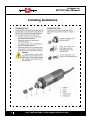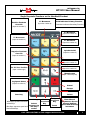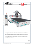
1
(HTT06681172)
BT1212 User Manual
Techno CNC Systems, LLC ©2015 (10/15)
NCstudio Controller
This document will provide a quick guide
to the operation of the Techno BT1212
CNC Router equipped with a NCstudio
Controller.
The BT1212 CNC Router is powered by high
precision stepper motors and controlled by
a hand-held NCstudio controller.
Call: 1-631-648-7481 or Visit: support.technocnc.com
1
(HTT06681172)
BT1212 User Manual
TABLE OF CONTENTS
I
II
Safety Instructions
Colleting Guidelines
............................................................... Page 3
............................................................... Page 4
NCStudio Controller Functionality
Functions of the Keys
..................................... Page 5
Shift Commands / Combination Keys ..................................... Page 6
III Operating Tutorials
3.0- Switching Movement to Step or Jog
........................ Page 7
3.1- Jogging the Machine and
Changing from High/Low Jog Speed
........................ Page 7
3.2- Stepping the machine
........................ Page 7
3.3- Modifying the Jog Speed and Step Size
3.4- Feedrate Override
........................ Page 8
3.5- Adjusting the XYZ Position/WCS/User Origin ........... Page 9
3.6- Loading a G-code file
.................................................. Page 10
3.7- Running a G-code File
.................................................. Page 11
IV
Advanced Tutorials
4.1- Alternating between Override and Programmed Feedrates .. Page 12
4.2- Setting Override speed for a G-code file
......................... Page 13
4.3- Setting the Table Size
......................... Page 14
Changing to Different Offset (a new XY Zero location) ............ Page 15
Pulse Equiv (scale factors)
......................... Page 16
Notes on the G-code file
......................... Page 16
Acceleration Set......................... Page 16
V Appendix
Using the 4th Axis on a BT1212 Machine
Page 17
WarrantyPage 18
2
Call: 1-631-648-7481 or Visit: support.technocnc.com
(HTT06681172)
BT1212 User Manual
Safety Instructions
READ THESE INSTRUCTIONS THOROUGHLY BEFORE OPERATING MACHINE. DO NOT OPERATE
MACHINE IF YOU ARE UNFAMILIAR WITH THESE SAFE OPERATING INSTRUCTIONS. DO NOT
OPERATE MACHINE WITHOUT KNOWING WHERE THE EMERGENCY STOP SWITCH IS LOCATED.
WARNING: IMPROPER OR UNSAFE OPERATION OF THE MACHINE WILL
RESULT IN PERSONAL INJURY AND/OR DAMAGE TO THE EQUIPMENT.
1.
Keep fingers, hands, and all other objects away from
machine while power is on.
12. Stay alert at all times when operating the machine.
2.
Disconnect power to all system components when
not in use, when changing accessories, and before
servicing.
3.
Do not loosen, remove, or adjust machine parts or
cables while power is on.
15. Always maintain proper balance and footing when
working around the machine.
4.
Exercise care with machine controls and around
keyboard to avoid unintentional starting.
5.
Make sure voltage supplied is appropriate to
specifications of components.
16. Maintain equipment with care. Keep cutting tools
clean and sharp. Lubricate and change accessories
when necessary. Cables and cords should be
inspected regularly. Keep controls clean and dry.
6.
Machines must be plugged into three-pronged
grounded outlets. Do not remove the grounding plug
or connect into an ungrounded extension cord.
7.
Keep cables and cords away from heat, oil, and
sharp edges. Do not overstretch or run them under
other objects or over work surfaces.
8.
Use proper fixtures and clamps to secure work. Never
use hands to secure work.
9.
Do not attempt to exceed limits of machine.
13. Always wear safety goggles.
14. Do not wear loose-fitting clothing when operating
machine. Long hair should be protected.
17. Before using, check for damaged parts. An
authorized service center should perform all repairs.
Only identical or authorized replacement parts should
be used.
18. Remove any adjusting keys and wrenches before
turning machine on.
19. Do not operate the machine unattended.
20. Follow all safety instructions and processing
instructions in the MSDS for the material being
processed.
10. Do not attempt to use machine for purposes other
than what is intended.
21. Use proper precautions with dust collection systems
to prevent sparks and fire hazards.
11. Use machine only in clean, well-lit areas free from
flammable liquids and excessive moisture.
22. Make sure to have proper fire extinguishing
equipment on hand at all times.
PREVENT FIRE HAZARDS by using the proper feeds, speeds, and tooling while operating your
Techno machine. For example, setting feeds and speeds too low and/or using dull tool bits creates
friction at the material. The friction generates heat which can result in a fire that can be drawn
through the vacuum table or dust collector without warning. Fire hazard from friction heating
caused by dull tools is possible when cutting certain materials, especially composite material
such as wood composites, MDF and Particleboard.
© 2015
Call: 1-631-648-7481 or Visit: support.technocnc.com
3
(HTT06681172)
BT1212 User Manual
Colleting Guidelines
4
Call: 1-631-648-7481 or Visit: support.technocnc.com
(HTT06681172)
BT1212 User Manual
Single Keystroke Functions on the Handheld Pendant
Y+ Movement
(Input the number 8)
Positive Feedrate
Override
(Input the number 7)
Bold Indicates Primary Function
(Parenthesis Indicates Secondary Function)
Z+ Movement
(Input the number 9)
X- Movement
(Input the number 4)
X+ Movement
(Input the number 6)
Spindle On/Off
(Input the number 5)
Negative Feedrate
Override
(Input the number 1)
Z- Movement
(Input the number 3)
Y- Movement
(Input the number 2)
Set XY Zero Position
(Input a minus sign)
Menu Screen
(Input a decimal point)
Jog Speed Select
(Input the number 0)
Stop
Cancel
Escape
OK
Start key
Yellow Keys represent movement
related keys
Select
Shift Key
Switch
between Jog
Blue Keys represent speed and
and Step
feed related keys
modes
Up
Down
Directional
Directional
Key
Key
Pause
Enter Manual
Parameters Screen
Change high/low
speed and XYZ step
increment
Call: 1-631-648-7481 or Visit: support.technocnc.com
5
(HTT06681172)
BT1212 User Manual
Shift Commands / Combination Keystrokes
To use the shift commands, you must press and hold the shift key and then select
a second key to use the Shift Command function.
Switch between work (relative) and machine (absolute)
Go to XYZ home (mechanical origin)
Go to current work (relative) origin
Set Z zero position manually not using Touch-Off pad
Resume from breakpoint M0 command
Open help screen
6
Call: 1-631-648-7481 or Visit: support.technocnc.com
(HTT06681172)
BT1212 User Manual
III Operating Tutorials.
3.0- Switching Movement to Step or Jog.
There are two modes that allow the user to control the movement of the
machine: Jog and Step. To switch between these modes press the “Shift” button.
The mode will be displayed on the bottom left of the screen.
Jog- Also known as continuous mode. When a directional arrow is pressed, the
machine will move in that direction until the button is released.
Stepping- Also known as step mode. When a directional arrow is pressed, the
machine will move an exact amount, as dictated by the manual parameters
page. To move again, you must release the button and press it again.
3.1- Jogging the machine and changing from High/Low Jog Speed.
To Jog the machine, hold down one of the Yellow directional keys on the keypad
while in Jog mode. The keypad has X+,X-,Y+,Y-,Z+,Z- printed on the keys to
indicate direction.
The machine has two speeds, High and Low.
When the machine starts it will be in the Low speed.
To toggle between low and high speed press the Jog Speed Select Button. You can
only toggle speed when in Jog Mode.
The LCD will display High or Low on the right of the screen.
Select between high and
low Jog speeds
Press ‘OK’ to change high and low speeds, see section 3.3.
3.2- Stepping the machine.
To move the machine in increments, press down one of the Yellow directional keys on the
keypad while in Stepping mode. The keypad has X+,X-,Y+,Y-,Z+,Z- printed on the keys to
indicate direction.
This will move the machine in predetermined increments in the axis selected.
By default, the X and Y axes will move in .005 inches and the Z axis will move in .001
inches.
Press ‘OK’ to change step size, see section 3.3
Call: 1-631-648-7481 or Visit: support.technocnc.com
7
(HTT06681172)
BT1212 User Manual
3.3- Modifying the Jog Speed and Step Size
The machine can be jogged at two speeds, low and high. You can also change the
increments in which the machine will move in Step mode. These speeds are set in
the Manual Parameters page.
To access the Manual Parameters page press OK from the Main Screen
Low Speed
High Speed
To move the cursor, use the Up and Down directional
arrows.
Enter a new value.
Press OK to accept that value.
XY Step Size
Set the High and Low speed to a suitable value.
Adjust the Step value as needed.
To Exit out of this screen and return to the main menu press ESC.
Warning: Adjust the step size carefully. If you set the step size to an excessive value, the
machine will move by that value and could damage the machine.
When inputting a decimal increment, you must enter the value as 0.###
Zero+decimal+(your increment)
3.4- Feedrate Override.
While running a G-Code file, the user can manually override the feedrate or
cutting speed of the program. The range of the override goes from 10% to 120%
of the original feedrate.
The user can override the feedrate using the following keys:
Increase
Feedrate
8
OR
Decrease
Feedrate
Call: 1-631-648-7481 or Visit: support.technocnc.com
(HTT06681172)
BT1212 User Manual
3.5- Adjusting the XYZ Zero position/WCS/User Origin.
XYZ zero position, Working Coordinate System (WCS), and
User Origin are all the same thing.
Different CAM systems and users just name the concept
differently. For convenience XYZ zero position will be used in
the rest of this manual.
XYZ zero position is the location point on a drawing in a
CAD/CAM package where X,Y and Z all equal zero.
Generally, XY zero is on the bottom left corner and Z zero
is the top of the part. In fig 3.3a the letters are located
away from the XY zero, all points representing positive
integers.
Fig. 3.3a
In Fig 3.3b the object represents the material the letters will
be cut from. The machine should be jogged to the corner of
the material by using the directional arrows on the keypad.
Once the machine is in location press to set XY zero. The
coordinates on the controller will change to 0,0.XY zero is
now set.
Fig.3.3b
There are two methods for setting the Z-axis zero position:
1. Manual Method: Use the Z-axis directional arrows on the
keypad to move the router to the top of the material. Switch
to Step Mode to slowly move the machine into position.
When the router bit is in position press shift/aux and the
Z=0 button as shown.
2. Tool Calibration Block: Place the touch off block on top
of the material and under the cutter. Press shift/aux and 0
simultaneously. The spindle will slowly move down until it
touches the touchpad. The Z axis will now be set to the top
of the material.
The Z coordinate will now read ‘Z 0.000’
+
Zero Z-axis
+
Activate Z-Touch off procedure.
Call: 1-631-648-7481 or Visit: support.technocnc.com
9
(HTT06681172)
BT1212 User Manual
3.6- Loading a G-code
File.
Press the Menu button.
Select “2.USB files” to access the flash drive.
Only a G-code file with an “nc” extension with show.
Scroll through the files with
and
Select file by pressing OK.
Then load the file by pressing 1.
Note:
Files can be copied from this USB to the controller using the “2” button
Local disk space is limited!
Once a file is copied locally, it can also be selected from the jog speed /step size screen
10
Call: 1-631-648-7481 or Visit: support.technocnc.com
(HTT06681172)
BT1212 User Manual
3.7- Running a G-code file.
Once the XYZ origin has been set as per section 3.5 and the file has been loaded as per section 3.6
the user is ready to run the G-code file.
To run the G-code file simply press the start button
Once the spindle has reached speed the machine will move into position to start the first cut.
The file can be paused while running by pressing
To resume the file press
.
To abort the file at any time press
.
Note:
When the machine pauses, the spindle will stop and the Z axis will move to the Z clearance/
Safe height to allow inspection of the part.
If the machine is jogged off the part during a pause, it will lose its position and when the file is
resumed it will start from the new position.
When using multiple tools it is best to create separate files for each tool.
The last file can be resumed at a breakpoint by pressing.
+
Call: 1-631-648-7481 or Visit: support.technocnc.com
11
(HTT06681172)
BT1212 User Manual
IV. Advanced Tutorials.
4.1- Alternating between Override and Programmed Feedrates.
The controller can run G-code files with speed set by the user on the keypad, override speed, or with
speed set in the CAM package/G-code file, programmed speeds.
To determine what speed protocol will be used, do the following:
In the main screen, press menu
Use the
and
to enter the menu screen .
key to scroll the cursor and highlight 4. oper param
Press OK to select.
Use the and
key scroll the cursor and highlight
8. ignore F code
9. ignore S code
Press OK to select.
Note:
The F or S Option.
F stands for Feed rates, and S stands for Spindle RPMS.
Note:
“No” means speed in the G-code file will be obeyed.
“Yes” means speed will be overrode by the controller.
12
Call: 1-631-648-7481 or Visit: support.technocnc.com
(HTT06681172)
BT1212 User Manual
4.2 Setting the Override Speed for a G-code file.
From the main screen, press Menu to access the Menu screen.
Use the arrow keys to move the cursor and
highlight
4. oper param
Press OK to select this option and enter the Operations Parameters screen
Use the arrow keys to move between each option and
press enter to select the option.
Press OK to edit the data and use the number keys to enter data.
Press OK to save data and Cancel to exit out of the screen.
Keep pressing cancel until you return to the main screen.
G00 Speed is the rapid speed, or the speed the machine moves when the cutter is above
the material.
GXX Speed is the speed the machine moves when the cutter is in the material. This speed
will vary with cutter size, material, cutter type, etc.
More parameters in
5. MFR param
Call: 1-631-648-7481 or Visit: support.technocnc.com
13
(HTT06681172)
BT1212 User Manual
4.3 Setting the Table Size.
From the main screen, press Menu to access the Menu screen.
Use the arrow keys to move the cursor and
highlight
5. MFR param
Press OK to select.
Password: 33587550
The MFR parameters screen will now open.
Use the arrow keys to move the cursor and highlight.
4. Machine stroke
Press OK to select.
Use the arrow keys to highlight a value, press OK to edit the value, and
press OK to save it.
Press Cancel when the value is highlighted to abort the edit.
Use the arrow keys to scroll down the screen until the negative values
are displayed.
When all the edits are complete, press Cancel to exit out of this screen.
Keep pressing cancel until you return to the main screen.
The asterisk * on this setting indicates that the machine must be powered down and the
axes homed in order for these new values to take affect.
If these values are incorrect it will effect the running of the machine.
If the values are too small, the machine will stall/stop when it reaches the value entered.
If the value is too big, it is possible for the machine to hit the end of travel and damage
could occur.
14
Call: 1-631-648-7481 or Visit: support.technocnc.com
(HTT06681172)
BT1212 User Manual
Press Menu
Operations
Select WCS
WSC
G54 Origin 1
G55 Origin 2 . . .
Call: 1-631-648-7481 or Visit: support.technocnc.com
15
(HTT06681172)
BT1212 User Manual
Pulse Equiv (scale factors)
X : 0.0012500
Y : 0.0012500
Z : 0.0012500
Notes On the G-code File
If a part requires multiple tools, it is best to output a different file for each part.
If the G-code file references a tool number higher than T10, then the controller will
give an error at the start of the file. M6 T1 to M6 T10 are allowed.
In general it is best to remove T commands by telling the CAM package that the
machine is not a tool changer machine, or insuring that the Tool number does not
exceed 10.
G92 is the Axis presetting command, when this command is encountered in the
G-code file the XYZ zero position is set at the position the machine is in at that time.
In general it is best to remove this from the G-code file, or if it is in the G-code file,
make sure the machine is at the origin before you press start.
The controller will recognise G54 to G59 offset commands.
See the NK105 G2 manual for more details on these commands.
Acceleration Set
Under the menu MFR Params, there is a sub menu called Velocity.
This menu controls the acceleration and cutting motion of the machine.
The Defaults for these parameters are:
Jerk
310
Single Axis Acc
25
Max Turn Acc
100
A low Max Turn Acc will result in arcs that move in a jerky motion or at a slow speed.
16
Call: 1-631-648-7481 or Visit: support.technocnc.com
(HTT06681172)
BT1212 User Manual
Using the 4th Axis on a BT1212 Machine
Note: The 4th axis on the stepper machine is not a true 4th axis. You can only use this to do
“wrapping” tool paths. This means that the file is designed as a regular, flat, 3-axis file which is
scaled so that the width matches the circumference of round stock. Then, instead of cutting flat,
the rotary is substituted for the Y-axis and the cut follows the circumference of the stock, as if it
is being “wrapped” around it.
To change over from normal 3-axis operation you must change some settings in the controller:
-
First, figure out the circumference of your stock. The formula is 3.14 x the diameter.
-
Press the “menu” button on the keypad. Go to “5. MFR Param”. The password is
33587550.
-
Go to “7. Y Rotary Axis > 1. Y Rotary Axis” and set to “YES”.
-
Go to “2. Rotary Y Pulse”. This is where you need to enter the scale factor. This will
change depending on the circumference of your stock. Take the circumference that you
calculated earlier and divide it by 12000. Enter the number you get here.
-
Exit the menu.
-
You must restart the controller for these new settings to be applied.
-
Once the machine is restarted, home as usual.
-
Now jog to your starting point and set your X, Y, and Z origin (0, 0, 0). Note: The Y-axis
will most likely move at a different speed than normal and the coordinates will not look
right.
-
Now change Y to the rotary axis using the switch on the front of the machine.
-
Run your file.
To change back to normal 3-axis operation, repeat the first 3 steps and set “7. Y Rotary Axis > 1.
Y Rotary Axis” back to “NO”.
Call: 1-631-648-7481 or Visit: support.technocnc.com
17
(HTT06681172)
www.technocnc.com
Tel: 631-648-7481
BT1212 User Manual
(HTT06091113)
9/2015
Techno CNC Systems, LLC., Terms and Conditions
For Limited Warranty and Repairs Warranty
WARRANTY
All Techno CNC Systems, LLC., mechanical components are warranted against manufacturer’s defects in material
and workmanship for a period of one (1) year from the time of shipment from Techno CNC Systems, LLC., facilities. All
Techno CNC Systems, LLC., electrical components are similarly warranted for a period of one (1) year from the time of
shipment from Techno CNC Systems, LLC., facilities. Techno CNC Systems, LLC.,’s sole obligation under this warranty
is limited to repairing the product or, at its option, replacing the product without additional charge, provided the item is
properly returned to Techno CNC Systems, LLC., for repair as described below. The provisions of this warranty shall
not apply to any product that has been subjected to tampering, abuse, improper setup or operating conditions, misuse,
lack of proper maintenance, or unauthorized user adjustment. Techno CNC Systems, LLC., makes no warranty that its
products are fit for any use or purpose to which they may be put by the customer, whether or not such use or purpose
has been disclosed to Techno CNC Systems, LLC., in specifications or drawings previously or subsequently provided,
and whether or not Techno CNC Systems, LLC.,’s products are specifically designed and/or manufactured for such a
purpose. NOTE: Drive motors (servo or stepper) are considered “mechanical components”.
THIS WARRANTY IS IN LIEU OF ALL OTHER WARRANTIES EXPRESSED OR IMPLIED. ALL OTHER WARRANTIES,
INCLUDING, BUT NOT LIMITED TO, ANY WARRANTY OF MERCHANTABILITY OR FITNESS FOR A PARTICULAR
PURPOSE, WHETHER EXPRESSED, IMPLIED, OR ARISING BY OPERATION OF LAW, TRADE USAGE, OR
COURSE OF DEALING, ARE HEREBY DISCLAIMED. THERE ARE NO WARRANTIES THAT EXTEND BEYOND
THE DESCRIPTION ON THE FACE HEREOF.
LIMITATION OF REMEDY
In no event shall Techno CNC Systems, LLC., be liable for any incidental, consequential, or special damages of any kind
or nature whatsoever. Techno CNC Systems, LLC., is in no way liable for any lost profits arising from or connected to this
agreement or items sold under this agreement, whether alleged to arise from breach of contract, expressed or implied
warranty, or in tort, including, without limitation, negligence, failure to warn, or strict liability.
RETURN PROCEDURE
Before returning any equipment in or out of warranty, the customer must first obtain a return authorization number and
packing instructions from Techno CNC Systems, LLC.,. No claim will be allowed nor credit given for products returned
without such authorization. Proper packaging and insurance for transportation is solely the customer’s responsibility.
After approval from Techno CNC Systems, LLC., the product should be returned with a statement of the problem and
transportation prepaid. If, upon examination, warranted defects exist, the product will be repaired or replaced at no
charge, and shipped prepaid back to the customer. Return shipment will be by common carrier (i.e., UPS). If rapid delivery
is requested by customer, then such transport is at the customer’s expense. If an out-of-warranty situation exists, the
customer will be notified of the repair costs immediately. At such time, the customer must issue a purchase order to
cover the cost of the repair or authorize the product to be shipped back as is, at the customer’s expense. In any case, a
restocking charge of 20% will be charged on all items returned to stock.
FIELD SERVICE
Repairs are ordinarily done at Techno CNC Systems, LLC.,’s Ronkonkoma, New York facility, where all necessary
instrumentation is available. This instrumentation is difficult to transport, so field service is severely limited, and will only
be supplied at Techno CNC Systems, LLC.,’s discretion. If field service is required and is performed at Techno CNC
Systems, LLC.,’s sole discretion, all relevant expenses, including transportation, travel time, subsistence costs, and the
prevailing cost per hour (eight hour minimum) are the responsibility of the customer.
UNFORESEEN CIRCUMSTANCES
Techno CNC Systems, LLC., is not liable for delay or failure to perform any obligations hereunder by reason of circumstances
beyond its reasonable control. These circumstances include, but are not limited to, accidents, acts of God, strikes or labor
disputes, laws, rules, or regulations of any government or government agency, fires, floods, delays or failures in delivery
of carriers or suppliers, shortages of materials, and any other event beyond Techno CNC Systems, LLC.,’s control.
ENTIRE AGREEMENT/GOVERNING LAW
The terms and conditions contained herein shall constitute the entire agreement concerning the terms and conditions
for the limited warranty described hereunder. No oral or other representations are in effect. This Agreement shall be
governed in all respects by the laws of New York State. No legal action may be taken by any party more than one (1)
year after the date of purchase.
TECHNO CNC SYSTEMS, LLC., RESERVES THE RIGHT TO CHANGE DESIGNS, SPECIFICATIONS, PRICES, AND
ANY APPLICABLE DOCUMENTATION WITHOUT PRIOR NOTICE.
18
Call: 1-631-648-7481 or Visit: support.technocnc.com