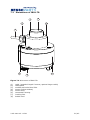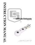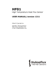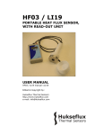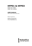
1
USER MANUAL IR02
Pyrgeometer with heater
Warning statements
Putting more than 12 Volt across the sensor wiring
can lead to permanent damage to the sensor.
Do not use “open circuit detection” when measuring
the sensor output.
ir02 manual v1301
2/43
Contents
Warning statements
Contents
List of symbols
Introduction
Ordering and checking at delivery
1
Ordering IR02
1.1
Included items
1.2
Quick instrument check
1.3
Instrument principle and theory
2
Pyrgeometer functionality
2.1
Solar and longwave radiation
2.2
IR02 pyrgeometer design
2.3
Typical measurement results
2.4
Optional heating
2.5
Use as a net radiation sensor
2.6
Specifications of IR02
3
Specifications of IR02
3.1
Dimensions of IR02
3.2
Standards and recommended practices for use
4
Site selection and installation
4.1
Electrical connection
4.2
Requirements for data acquisition / amplification
4.3
Making a dependable measurement
5
The concept of dependability
5.1
Reliability of the measurement
5.2
Speed of repair and maintenance / instrument lifetime
5.3
Uncertainty evaluation
5.4
Maintenance and trouble shooting
6
Recommended maintenance and quality assurance
6.1
Trouble shooting
6.2
Calibration and checks in the field
6.3
Data quality assurance
6.4
IR02-TR
7
Introduction IR02-TR
7.1
Dimensions of IR02-TR
7.2
Appendices
8
Appendix on cable extension / replacement
8.1
Appendix on tools for IR02
8.2
Appendix on spare parts for IR02
8.3
Appendix on standards for classification and calibration
8.4
Appendix on calibration hierarchy
8.5
Appendix on meteorological radiation quantities
8.6
Appendix on terminology / glossary
8.7
Appendix on conditions of sale: warranty and liability
8.8
EC declaration of conformity
8.9
ir02 manual v1301
2
3
4
5
7
7
7
8
9
9
9
11
13
13
13
14
14
17
18
19
20
21
22
22
23
24
25
26
26
27
28
28
29
29
31
34
34
35
35
36
36
38
39
40
41
3/43
List of symbols
Quantities
Symbol
Unit
Voltage output
Sensitivity at reference conditions
Temperature
Equivalent blackbody radiative temperature
Electrical resistance
Longwave irradiance
Stefan–Boltzmann constant (5.67 x 10⁻⁸)
U
S
T
T
Re
E
σ
V
V/(W/m2)
°C
°C
Ω
W/m2
W/(m2∙K4)
(see also appendix 8.6 on meteorological quantities)
Subscripts
sky
surface
ambient
body
sensor
ir02 manual v1301
relating
relating
relating
relating
relating
to
to
to
to
to
the atmosphere
the ground surface
ambient air
the instrument body
the sensor
4/43
Introduction
IR02 is a pyrgeometer suitable for longwave irradiance measurements in meteorological
applications. The instrument can be heated, which improves measurement accuracy as it
prevents dew deposition on its window.
IR02 measures the longwave or far-infra-red radiation received by a plane surface, in
W/m2, from a field of view angle of approximately 150o. Longwave radiation is the part of
radiation that is not emitted by the sun. The actual field of view angle of IR02 is not the
ideal 180o. The reduction of this field of view makes it possible to offer an instrument at
an attractive price level, while the accuracy loss is relatively small.
IR02 has a window with a solar blind filter with a cut-on at 4.5 x 10⁻⁶ m, making it
suitable for day- and night observations.
IR02 pyrgeometer has a high sensitivity. With sufficient input signal a typical datalogger
no longer contributes to the uncertainty of the measurement. IR02 also houses an onboard heater. Heating prevents dew deposition and condensation which, when occurring,
leads to very large measurement errors.
Using IR02 is easy. It can be connected directly to commonly used data logging systems.
The irradiance in W/m2 is calculated by dividing the IR02 output, a small voltage, by the
sensitivity and taking in account the irradiated heat by the sensor itself (StefanBoltzmann law). The sensitivity is provided with IR02 on its calibration certificate.
The central measurement equation governing IR02 is:
E = U/S + σ·(T + 273.15)4
(Formula 0.1)
The instrument should be used in accordance with the recommended practices of the
World Meteorological Organization (WMO).
Suggested use for IR02:
•
•
•
general meteorological observations
climatological networks
agricultural networks
ir02 manual v1301
5/43
Figure 0.1 IR02 pyrgeometer with heater
Calibration of pyrgeometers used for downward longwave radiation is traceable to the
World Infrared Standard Group (WISG). This calibration takes into account the spectral
properties of typical downward longwave radiation. As an option, calibration can be made
traceable to a blackbody and the International Temperature Scale of 1990 (ITS-90). This
alternative calibration is appropriate for measurements of upward longwave radiation
(with IR02 pyrgeometers facing down).
Model IR02-TR houses a 4-20 mA transmitter for easy read-out by dataloggers
commonly used in the industry. For more information, see the chapter on IR02-TR.
ir02 manual v1301
6/43
1
Ordering and checking at delivery
1.1
Ordering IR02
The standard configuration of IR02 is with 5 metres cable.
Common options are:
•
•
•
•
Longer cable (in multiples of 5 m). Specify total cable length.
IR02-TR pyrgeometer with heater and 4-20 mA transmitter. Standard setting is 4 mA
at -300 W/m2 and 20 mA at 100 W/m2. Specify setting and total cable length.
Internal temperature sensor. This can be either a Pt100 (standard configuration) or a
10 kΩ thermistor (optional). Specify respectively T1 or T2.
Optional calibration to blackbody (ITS-90).
Supply of products is subject to Hukseflux’ General Conditions of Sale. The product
warranty (involving repair or replacement without charge for product or working hours) is
24 months.
Hukseflux does not accept any liability for losses or damages related to use of the
supplied products. See the appendix and Hukseflux’ General Conditions of Sale for
detailed statements on warranty and liability.
1.2
Included items
Arriving at the customer, the delivery should include:
•
•
•
•
pyrgeometer IR02
cable of the length as ordered
product certificate matching the instrument serial number
any other options as ordered
Please store the certificate in a safe place.
ir02 manual v1301
7/43
1.3
Quick instrument check
A quick test of the instrument can be done by using a simple hand held multimeter and a
thermal source.
1. Check the electrical resistance of the sensor between the green (-) and white (+) wire.
Use a multimeter at the 1000 Ω range. Measure the sensor resistance first with one
polarity, than reverse the polarity. Take the average value. The typical resistance of the
wiring is 0.1 Ω/m. Typical resistance should be the typical sensor resistance of 100 to
400 Ω plus 1.5 Ω for the total resistance of two wires (back and forth) of each 5 m.
Infinite resistance indicates a broken circuit; zero or a low resistance indicates a short
circuit.
2. Check if the sensor reacts to heat: put the multimeter at its most sensitive range of
DC voltage measurement, typically the 100 x 10-3 VDC range or lower. Make sure that
the sensor is at 20 °C or lower. Expose the sensor to a strong heat source at a short
distance from the window of more than 50 °C, for instance a hot cup of coffee. The signal
should read positive and > 1 x 10⁻³ V now. In case of using your hand as a heat source,
the signal should be significantly lower.
3. Inspect the bubble level.
4. Check the electrical resistance of the Pt100. This should be in the 100 Ω range. In
case of use of a 10 kΩ thermistor it should be in the 10 4 Ω range
5. Check the electrical resistance of the heater. This should be in the 100 Ω range.
6. Inspect the instrument for any damage.
ir02 manual v1301
8/43
2
Instrument principle and theory
2.1
Pyrgeometer functionality
IR02’s scientific name is pyrgeometer. IR02 measures the longwave or far-infra-red (FIR)
radiation received by a plane surface, in W/m2, ideally from a 180° field of view angle. In
meteorological terms pyrgeometers are used to measure “downward and upward
longwave irradiance” (WMO definition). In case of IR02 the ideal 180° field of view angle
has been reduced to 150°. This makes it possible to offer an instrument at an attractive
price level, while the loss of accuracy is relatively small.
As secondary measurands, the sky temperature T sky , and the equivalent surface (ground)
temperature T surface can be measured. Both are so-called equivalent blackbody radiative
temperatures, i.e. temperatures calculated from the pyrgeometer measurement
assuming these are uniform-temperature blackbodies with an emission coefficient of 1.
2.2
Solar and longwave radiation
Longwave radiation is the part of the radiation budget that is not emitted by the sun. The
spectral range of the longwave radiation is not standardised. A practical cut-on is in the
range of 4 to 5 x 10⁻⁶ m (see figure 2.2.1). In meteorology, solar- and longwave
radiation are typically measured as separate parameters. The instrument to measure
solar radiation is called pyranometer.
In the longwave spectrum, the sky can be seen as a temperature source; colder than
ground level ambient air temperature, with its lowest temperatures at zenith, getting
warmer (closer to ambient air temperature) at the horizon. The uniformity of this
longwave source is much better than that in the range of the solar spectrum, where the
sun is a dominant contributor. The “equivalent blackbody” temperature, as a function of
zenith angle, roughly follows the same pattern independent of the exact sky condition
(cloudy or clear). This explains why for pyrgeometers the directional response is not very
critical.
ir02 manual v1301
9/43
spectral irradiance x 10-9 W/(m2/m)
1,000
downwelling
longwave
solar
0,100
0,010
0,001
1
10
100
wavelength x 10-6 m
Figure 2.2.1 Atmospheric radiation as a function of wavelength plotted along two
logarithmic axes to highlight the longwave radiation. Longwave radiation is mainly
present in the 4 to 50 x 10-6 m range, whereas solar radiation is mainly present in the
0.3 to 3 x 10⁻⁶ m range. In practice, the two are measured separately using
pyrgeometers and pyranometers
The downwelling longwave radiation essentially consists of several components:
1. low temperature radiation from the universe, filtered by the atmosphere. The
atmosphere is transparent for this radiation in the so-called atmospheric window (roughly
the 10 to 15 x 10-6 m wavelength range).
2. higher temperature radiation emitted by atmospheric gasses and aerosols.
3. in presence of clouds or mist, the low temperature radiation from the universe is
almost completely blocked by the water droplets. The pyrgeometer then receives the
radiation emitted by the water droplets.
Upwelling longwave irradiance is measured with downfacing instruments. These are
presumably looking directly at the surface (absorption and emission of the atmosphere is
low over a short distance of around 2 m), which behaves like a normal blackbody.
Hukseflux suggests calibrating downfacing instruments against a blackbody rather than
having WISG as a reference.
ir02 manual v1301
10/43
Table 3.1.1 Specifications of IR02 (continued)
ADDITIONAL SPECIFICATIONS
Zero offset b (response to 5 K/h change
in ambient temperature)
Non-stability
Non-linearity
Measurement range
Tilt dependence
Sensor resistance range
Expected voltage output
Measurement function / required
programming
Measurement function / optional
programming for sky temperature
Measurement function / optional
programming for surface temperature
Required readout
STANDARDS
Standard governing use of the
instrument
MOUNTING, CABLING, TRANSPORT
Standard cable length (see options)
Cable diameter
Cable replacement
Instrument mounting
Levelling
Levelling accuracy
IP protection class
Gross weight including 5 m cable
Net weight including 5 m cable
Packaging
ir02 manual v1301
< ± 4 W/m2
< ± 1 % change per year
< ± 2.5 % (100 to 300 W/m2, relative to 200 W/m2
sensor to source exchange)
-300 to +300 W/m2
(sensor to source exchange: U/S)
< ± 2 % (0 to 90° at 300 W/m2)
100 to 400 Ω
application for outdoor measurement of downward
longwave irradiance: -7.5 to 7.5 x 10⁻³ V
E = U/S + σ·(T + 273.15)4
T sky = (E l /σ)1/4 + 273.15
T surface = (E l /σ)1/4 + 273.15
1 differential voltage channel or 1 single ended
voltage channel, input resistance > 106 Ω
1 temperature channel
WMO-No. 8, Guide to Meteorological Instruments and
Methods of Observation, seventh edition 2008,
paragraph 7.4 "measurement of total and long-wave
radiation"
5m
5.3 x 10⁻³ m
IR02 cable is potted and cannot be replaced
2 x M5 bolt at 65 x 10-3 m centre-to-centre distance
on north-south axis
bubble level and adjustable levelling feet are included
< 0.4° bubble entirely in ring
IP 67
0.5 kg
0.3 kg
box of (170 x 90 x 230) x 10-3 m
15/43
3
Specifications of IR02
3.1
Specifications of IR02
IR02 pyrgeometer measures the longwave irradiance received by a plane surface, in
W/m2, from a 150° field of view angle, which approximates the ideal 180° field of view
angle. In meteorological terms IR02 measures downward and upward longwave
irradiance. Working completely passive, using a thermopile sensor, IR02 generates a
small output voltage proportional to the radiation balance between the instrument and
the source it faces. It can only be used in combination with a suitable measurement
system. The instrument is not subject to classification. It should be used in accordance
with the recommended practices of WMO. IR02 measures during both day and night. For
high accuracy measurements the user should consider to use the incorporated heater.
Table 3.1.1 Specifications of IR02
IR02 SPECIFICATIONS
MEASURANDS
Measurand
Measurand in SI radiometry units
Optional measurand
Optional measurand
Spectral range IR02
Solar offset
MAIN SPECIFICATIONS
Field of view angle
Response time (95 %)
Sensitivity (nominal)
Sensitivity range
Rated operating temperature range
Temperature dependence
Temperature sensor
Required sensor power
Heater
Standard cable length
ir02 manual v1301
longwave radiation
longwave irradiance in W/m2
sky temperature
surface temperature
4.5 to 40 x 10-6 m
(nominal, see product certificate for individual value)
< 15 W/m2
(at 1000 W/m2 global horizontal irradiance on the dome)
150°
18 s
15 x 10-6 V/(W/m2)
5 to 15 x 10-6 V/(W/m2)
-40 to +80 °C
< ± 3 % (-10 to +40 °C)
Pt100
zero (passive sensor)
12 VDC, 1.5 W
(see below for details)
5m
14/43
2.4
Typical measurement results
Please note that the signal generated by an upfacing pyrgeometer usually has a negative
sign.
The most important factors determining downward longwave irradiance are:
•
•
•
ambient air temperature
sky condition / cloud cover
atmospheric moisture content
Table 2.4.1 Expected pyrgeometer output U/S at different ambient air temperatures,
Tambient , and at different cloud conditions. Under clear sky conditions the U/S is around
-100 W/m2 while under cloudy conditions it will be close to 0 W/m2. Also calculated: the
sky temperature, T sky , and the longwave downward irradiance E.
EXPECTED PYRGEOMETER OUTPUT CONDITIONS
2.5
T ambient
[°C]
Sky condition
[cloudy], [clear]
U/S
[W/m2]
T sky
[°C]
E
[W/m2]
-20
-20
0
0
+30
+30
cloudy
clear sky
cloudy
clear sky
cloudy
clear sky
0
-100
0
-100
0
-100
-20
-53
+0
-24
+30
+12
232
132
314
214
477
377
Optional heating
A low-power heater is located in the body of the pyrgeometer. The heater is not
necessarily switched on; recommended operation is to activate the heater when there is
a risk of dew deposition.
2.6
Use as a net radiation sensor
Two pyrgeometers mounted back to back may be used to measure net longwave
radiation. Net longwave radiation is defined as downwelling minus upwelling longwave
irradiance. In case the two instruments are thermally coupled, the body temperatures of
the instruments are identical. In that case the body temperature cancels from the
equation for the net radiation. However for calculation of sky temperature and surface
temperature the instrument temperature still needs to be measured.
See also model NR01, a 4-component net radiometer.
ir02 manual v1301
13/43
A pyrgeometer should have a so-called “directional response” (older documents mention
“cosine response”) that is as close as possible to the ideal cosine characteristic.
In order to attain the proper directional and spectral characteristics, a pyrgeometer’s
main components are:
•
a thermal sensor with black coating. It has a flat spectrum covering the
0.3 to 50 x 10-6 m range, and has a near-perfect directional response. The coating
absorbs all longwave radiation and, at the moment of absorption, converts it to heat.
The heat flows through the sensor to the sensor body. The thermopile sensor
generates a voltage output signal that is proportional to the irradiance exchange
between sensor and source. The sensor not only absorbs, but also irradiates heat as a
blackbody.
•
a silicon window. This dome limits the spectral range from 1.0 to 40 x 10-6 m (cutting
off the part below 1.0 x 10⁻⁶ m), while preserving as much as possible the ideal 180°
field of view angle. Another function of the window or dome is that it shields the
thermopile sensor from the environment (convection, rain).
•
a solar blind interference coating deposited on the window: this coating limits the
spectral range. It now becomes 4.5 to 40 x 10-6 m (cutting off the part below 4.5 x
10-6 m).
Pyrgeometers can be manufactured to different specifications and with different levels of
verification and characterisation during production. Hukseflux also manufactures higher
accuracy pyrgeometers; see pyrgeometer model IR20.
ir02 manual v1301
12/43
2.3
IR02 pyrgeometer design
3
4
2
5
1
8
6
7
Figure 2.3.1 Overview of IR02 pyrgeometer:
(1)
(2)
(3)
(4)
(5)
(6)
(7)
(8)
cable, (standard length 5 metres, optional longer cable)
cable gland
window with solar blind filter
sensor (below window)
sensor body
levelling feet
mounting hole
bubble level
By definition a pyrgeometer should not measure solar radiation, and in the longwave
have a spectral selectivity that is as “flat” as possible.
In an irradiance measurement by definition the response to “beam” radiation varies with
the cosine of the angle of incidence; i.e. it should have full response when the radiation
hits the sensor perpendicularly (normal to the surface, 0° angle of incidence), zero
response when the source is at the horizon (90° angle of incidence, 90° zenith angle),
and 50 % of full response at 60° angle of incidence.
ir02 manual v1301
11/43
Table 3.1.1 Specifications of IR02 (started on previous pages)
HEATING
Heater operation
Required heater power
Heater resistance
Steady state zero offset caused by
heating
CALIBRATION
Calibration traceability
Optional traceability
Calibration hierarchy
Calibration method
Calibration uncertainty
Recommended recalibration interval
Reference conditions
Validity of calibration
MEASUREMENT ACCURACY
Uncertainty of the measurement
Achievable uncertainty (95 % confidence
level) daily totals
VERSIONS / OPTIONS
Longer cable, in multiples of 5 m
Calibration
4-20 mA transmitter
Internal temperature sensor
Longer cable, in multiples of 5 m
ir02 manual v1301
the heater is not necessarily switched on;
recommended operation is to activate the heater
when there is a risk of dew deposition
1.5 W at 12 VDC
95 Ω
0 W/m2
to WISG
to blackbody (ITS-90 )
from WISG through Hukseflux internal calibration
procedure employing a blackbody
indoor calibration under a blackbody, by comparison
reference pyrgeometer traceable to WISG
< 7 % (k = 2)
2 years
horizontal mounting, atmospheric longwave
irradiance, clear sky nights, 20 °C
based on experience the instrument sensitivity will not
change during storage. During use under exposure to
solar radiation the instrument “non-stability”
specification is applicable.
Hukseflux recommends ITS-90 traceable calibration
for upward longwave irradiance measurement.
statements about the overall measurement
uncertainty can only be made on an individual basis.
See the chapter on uncertainty evaluation
± 15 % (Hukseflux’ own estimate)
option code = total cable length
optional to blackbody (ITS-90 )
creating a 4-20 mA output signal,
option code = TR,
with adapted housing
standard setting is 4 x 10⁻⁶ A at -300 W/m2 and
20 x 10-6 A at +100 W/m2
heater and internal temperature sensor directly
connected to cable wire
for specifications see the chapter on IR02-TR
measuring the body temperature:
version code = T1 for Pt100 DIN class A,
version code = T2 for thermistor 10 kΩ at 25 °C
option code = total cable length
16/43
3.2
Dimensions of IR02
22
46
Ø 78
65
M5 (2x)
Figure 3.2.1 Dimensions of IR02 in 10-3 m
ir02 manual v1301
17/43
4
Standards and recommended practices
for use
Pyrgeometers are not subject to standardisation.
The World Meteorological Organization (WMO) is a specialised agency of the United
Nations. It is the UN system's authoritative voice on the state and behaviour of the
earth's atmosphere and climate. WMO publishes WMO-No. 8; Guide to Meteorological
Instruments and Methods of Observation, in which paragraph 7.4 covers "measurement
of total and long-wave radiation".
For ultra high accuracy measurements, the following manual may serve as a reference:
Baseline Surface Radiation Network (BSRN) Operations Manual, Version 2.1, L. J. B.
McArthur, April 2005, WCRP-121, WMO/TD-No. 1274.
This manual also includes chapters on installation (paragraph 4.1) and calibration
(paragraph 8.4).
ir02 manual v1301
18/43
4.1
Site selection and installation
Table 4.1.1 Recommendations for installation of pyrgeometers
Location
the horizon should be as free from obstacles as
possible.
Mechanical mounting / thermal insulation
preferably use connection by bolts to the bottom plate
of the instrument. A pyrgeometer is sensitive to
thermal shocks. Do not mount the instrument with the
body in direct thermal contact to the mounting plate
(so always use the levelling feet also if the mounting
is not horizontal), do not mount the instrument on
objects that become very hot (black coated metal
plates).
Instrument mounting with 2 bolts
2 x M5 bolt at 65 x 10-3 m centre-to-centre distance
on north-south axis, connection through the
pyrgeometer flange.
Performing a representative
measurement
the pyrgeometer measures the solar radiation in the
plane of the sensor. This may require installation in a
tilted or inverted position. The sensor surface (sensor
bottom plate) should be mounted parallel to the plane
of interest.
In case a pyrgeometer is not mounted horizontally or
in case the horizon is obstructed, the
representativeness of the location becomes an
important element of the measurement. See the
chapter on uncertainty evaluation.
Levelling
in case of horizontal mounting only use the bubble
level and levelling feet.
Instrument orientation
by convention with the cable exit pointing to the
nearest pole (so the cable exit should point north in
the northern hemisphere, south in the southern
hemisphere).
Installation height
in case of inverted installation, WMO recommends a
distance of 1.5 m between soil surface and sensor
(reducing the effect of shadows and in order to obtain
good spatial averaging).
ir02 manual v1301
19/43
4.2
Electrical connection
In order to operate, a pyrgeometer should be connected to a measurement system,
typically a so-called datalogger. IR02 is a passive sensor that does not need any power.
Cables generally act as a source of distortion, by picking up capacitive noise. We
recommend keeping the distance between a datalogger or amplifier and the sensor as
short as possible. For cable extension, see the appendix on this subject.
Table 4.2.1 The electrical connection of IR02. The heater is not necessarily used. The
temperature sensor must be used.
PIN
WIRE
IR02
1
Red
Pt100 [+]
2
White
Pt100 [+]
3
Blue
Pt100 [−]
4
Green
Pt100 [−]
5
Brown
heater
6
Yellow
heater
7
Black
ground
8
Pink
signal [+]
9
Grey
signal [−]
Note 1: optional 10 kΩ thermistors are internally connected in a 4-wire configuration like
the Pt100 but usually connected to electronics used in 2-wire configuration.
Note 2: the heater is not necessarily connected. In case it is connected, the polarity of
the connection is not important.
Note 3: signal wires are insulated from ground wire and from the sensor body. Insulation
resistance is tested during production and larger than 1 x 10⁶ Ω.
Note 4: ground is connected to the connector, the sensor body and the shield of the wire.
Figure 4.2.1 Electrical diagram of the internal wiring of IR02. The shield is connected to
the sensor body.
ir02 manual v1301
20/43
4.3
Requirements for data acquisition / amplification
The selection and programming of dataloggers is the responsibility of the user. Please
contact the supplier of the data acquisition and amplification equipment to see if
directions for use with the IR02 are available.
In case programming for similar instruments is available, this can typically also be used.
IR02 can usually be treated in the same way as other thermopile pyrgeometers.
Table 4.3.1 Requirements for data acquisition and amplification equipment for IR02 in
the standard configuration
Capability to measure small voltage
signals
preferably: better than 5 x 10⁻⁶ V uncertainty
Minimum requirement: 20 x 10-6 V uncertainty
(valid for the entire expected temperature range of the
acquisition / amplification equipment)
Capability for the data logger or the
software
to store data, and to perform division by the sensitivity to
calculate the longwave irradiance.
E = U/S + σ·(T + 273.15)4 (Formula 0.1)
(see also optional measurands)
Data acquisition input resistance
> 1 x 10⁶ Ω
Open circuit detection
(WARNING)
open-circuit detection should not be used, unless this is done
separately from the normal measurement by more than 5
times the sensor response time and with a small current
only. Thermopile sensors are sensitive to the current that is
used during open circuit detection. The current will generate
heat, which is measured and will appear as an offset.
Capability to measure temperature
a Pt100 (or optional thermistor) must be read-out. Required
accuracy of the readout is ± 0.2 °C, which results in around
1 W/m2 uncertainty of the irradiance measurement.
Capability to power the heater
(OPTIONAL)
IR02 has a 12 VDC, 1.5 W heater on board, which may
optionally be activated to keep the instrument above dew
point. Some users prefer to have the heater on full time,
others prefer to switch it on during nighttime only.
ir02 manual v1301
21/43
5
Making a dependable measurement
5.1
The concept of dependability
A measurement with a pyrgeometer is called “dependable” if it is reliable, i.e. measuring
within required uncertainty limits, for most of the time and if problems, once they occur,
can be solved quickly.
The requirements for a measurement with a pyrgeometer may be expressed by the user
as:
•
•
•
required uncertainty of the measurement (see following paragraphs)
requirements for maintenance and repairs (possibilities for maintenance and repair
including effort to be made and processing time)
a requirement to the expected instrument lifetime (until it is no longer feasible to
repair)
It is important to realise that the uncertainty of the measurement is not only determined
by the instrument but also by the way it is used.
In case of pyrgeometers, the measurement uncertainty as obtained during outdoor
measurements is a function of:
•
•
•
•
the instrument properties
the calibration procedure / uncertainty
the presence of natural sunlight (involving the instrument specification of solar offset)
the measurement conditions (such as tilting, ventilation, shading, heating, instrument
temperature)
• maintenance (mainly fouling and deposition of water)
• the environmental conditions* (such as temperature, position of the sun, presence of
clouds, horizon, representativeness of the location)
Therefore statements about the overall measurement uncertainty under outdoor
conditions can only be made on an individual basis, taking all these factors into account.
* defined at Hukseflux as all factors outside the instrument that are relevant to the
measurement such as the cloud cover (presence or absence of direct radiation), sun
position, the local horizon (which may be obstructed) or condition of the ground (when
inverted). The environmental conditions also involve the question whether or not the
measurement at the location of measurement is representative of the quantity that
should be measured.
ir02 manual v1301
22/43
5.2
Reliability of the measurement
A measurement is reliable if it measures within required uncertainty limits for most of the
time. We distinguish between two causes of unreliability of the measurement:
•
•
related to the reliability of the pyrgeometer and its design, manufacturing, calibration
(hardware reliability).
related to the reliability of the measurement uncertainty (measurement reliability),
which involves hardware reliability as well as condition of use.
Most of the hardware reliability is the responsibility of the instrument manufacturer.
The reliability of the measurement however is a joint responsibility of instrument
manufacturer and user. As a function of user requirements, taking into account
measurement conditions and environmental conditions, the user will select an instrument
of a certain class, and define maintenance support procedures.
In many situations there is a limit to a realistically attainable accuracy level. This is due
to conditions that are beyond control once the measurement system is in place. Typical
limiting conditions are:
•
•
•
the measurement conditions, for instance when working at extreme temperatures
when the instrument temperature is at the extreme limits of the rated temperature
range.
the environmental conditions, for instance when installed at a sub-optimal
measurement location with obstacles in the field of view.
the environmental conditions, for instance when assessing net radiation, the
downfacing pyrgeometer measurement may not be representative of irradiance
received in that particular area.
The measurement reliability can be improved by maintenance support. Important aspects
are:
•
•
•
dome fouling by deposition of dust, dew, rain or snow. With pyrgeometers the most
important source of unreliability is deposition of water on the dome. Water completely
blocks the longwave radiation flux between sensor and sky. In particular at clear
nights this causes very large errors. Water deposition under clear-sky nighttime
conditions can largely be prevented by using the instrument heater. Fouling results in
undefined measurement uncertainty (sensitivity and directional error are no longer
defined). This should be solved by regular inspection and cleaning.
sensor instability. Maximum expected sensor aging is specified per instrument as its
non-stability in [% change / year]. In case the sensor is not recalibrated, the
uncertainty of the sensitivity gradually will increase. This is solved by regular
recalibration.
moisture condensing under pyrgeometer domes resulting in a slow change of
sensitivity (within specifications). For non-serviceable sensors like Hukseflux’ flat
window pyrgeometers, such as model IR02, this may slowly develop into a defect. For
research-grade model IR20 extra desiccant (in a set of 5 bags in an air tight bag) is
available.
ir02 manual v1301
23/43
•
One of the larger errors in the daytime measurement of downwelling longwave
irradiance is the offset caused by solar radiation; the “solar offset”. Errors due to
solar offset, are of the order of +15 W/m2 at 1000 W/m2 global horizontal irradiance.
For ultra-high accuracy measurements this offset can be reduced by around 60% by
“shading”, which means preventing the direct radiation to reach the instrument.
Shading is typically done by using a shading disk on a solar tracker. Shading is often
applied with research-grade pyrgeometers like Hukseflux model IR20. The overall
accuracy of model IR02 does not justify use of shading.
Another way to improve measurement reliability is to introduce redundant sensors.
•
The use of redundant instruments allows remote checks of one instrument using the
other as a reference, which leads to a higher measurement reliability.
5.3
Speed of repair and maintenance / instrument lifetime
Dependability is not only a matter of reliability but also involves the reaction to
problems; if the processing time of service and repairs is short, this contributes to the
dependability.
Hukseflux pyrgeometers are designed to allow easy maintenance and repair. The main
maintenance actions are:
•
replacement of cabling and cable gland; please note that with IR02 the cable is
potted inside the cable gland.
For optimisation of dependability a user should:
•
•
•
estimate the expected lifetime of the instrument
design a schedule of regular maintenance
design a schedule of repair or replacement in case of defects
When operating multiple instruments in a network Hukseflux recommends keeping
procedures simple and having a few spare instruments to act as replacements during
service, recalibrations and repair.
Hukseflux pyrgeometers are designed to be suitable for the intended use for at least 5
years under normal meteorological conditions. Factory warranty (granting free of charge
repair) for defects that are clearly traceable to errors in production is 2 years.
The “product expected lifetime” is defined as the minimum number of years of
employment with normal level of maintenance support, until the instrument is no longer
suitable for its intended use (cannot be repaired). For pyrgeometers, the product
expected lifetime depends heavily on the environmental conditions. Examples of
environments with reduced expected lifetime are areas with high levels of air pollution
and areas with high levels of salt in the air. Both cause enhanced corrosion. It is not
possible to give a generally applicable statement about expected lifetime. In Hukseflux’
ir02 manual v1301
24/43
experience it is not realistic to expect a lifetime longer than 10 years except in very dry
environments such as very dry tropical or polar climates.
5.4
Uncertainty evaluation
The uncertainty of a measurement under outdoor or indoor conditions depends on many
factors, see paragraph 1 of this chapter. It is not possible to give one figure for
pyrgeometer measurement uncertainty. The work on uncertainty evaluation is “in
progress”. There are several groups around the world participating in standardisation of
the method of calculation. The effort aims to work according to the guidelines for
uncertainty evaluation (according to the “Guide to Expression of Uncertainty in
Measurement” or GUM).
The main ingredients of the uncertainty evaluation for pyrgeometers are:
•
•
•
•
•
•
•
Calibration uncertainty, which is in the order of ±7 % (k = 2) for upfacing
instruments measuring downward longwave irradiance
Calibration uncertainty, which is larger for other than upfacing instruments; for
downfacing instruments a blackbody calibration seems preferable. Blackbody
calibration will result in a lower sensitivity, S, than WISG traceable calibraton.
Errors due to water deposition at clear nights; these completely block the longwave
irradiance exchange between pyrgeometer and may cause the signal U/S to change
from a large negative value (-100 W/m2) to around 0 W/m2 . Water deposition at
clear nights may largely be avoided by using the on-board heater of IR02.
Errors due to solar offset, which is of the order of +15 W/m2 at 1000 W/m2 global
horizontal irradiance. This uncertainty is not taken into account in the WISG
calibration of the reference instrument.
Errors due to the choice of the cut-on wavelength of the pyrgeometer. Depending on
the atmospheric water content, the pyrgeometer will block a variable percentage of
the downward longwave irradiance. This causes an uncertainty of the sensitivity S.
With IR02, this uncertainty is already taken into account in the WISG calibration of
the reference instrument.
Errors due to instrument non-stability. This is now estimated at < ±1 % change per
year. The main factor in instrument non-stability is the aging of the pyrgeometer
solar blind filter.
Errors due to the temperature measurement T. For this a Pt100 or optional 10 kΩ
thermistor must be read-out. Required accuracy of the readout is ±0.2 °C, which
results in around 1 W/m2 uncertainty of the irradiance measurement. To this the
uncertainty of the thermistor itself should be added. In measurement of net radiation,
in case the upfacing and downfacing instruments are thermally coupled, the
temperature measurement (and also its uncertainty) cancel from the equation.
ir02 manual v1301
25/43
Table 7.1.1 Specifications of IR02-TR
IR02-TR SPECIFICATIONS
Description
Transmitted range
Output signal
Principle
Supply voltage
Options
Mounting
pyrgeometer with heater and with 4-20 mA transmitter
-300 to +100 W/m2
4 to 20 x 10-3 A
2-wire current loop
7.2 to 35 VDC
adapted transmitted range
longer cable, in multiples of 5 m
2 x M5 bolt at 65 mm centre-to-centre distance on northsouth axis, or 1 x M6 bolt at the centre of the instrument,
connection from below under the bottom plate of the
instrument
Table 7.1.2 Requirements for data acquisition and amplification equipment with the
IR02–TR configuration
Capability to
- measure 4-20 mA or
- measure currents or
- measure voltages
The IR02-TR has a 4-20 mA output as well as a temperature
sensor (see next row) which both must be read out.
Concerning the 4-20 mA signal, there are several
possibilities to handle this signal. It is important to realise
that the signal wires not only act to transmit the signal but
also act as power supply.
Some dataloggers have a 4-20 mA input. In that case the
connection can be directly made.
Some dataloggers have the capability to measure currents.
In some cases the datalogger accepts a voltage input.
Usually a 100 Ω precision resistor is used to convert the
current to a voltage (this will then be in the 0.4 – to 2 VDC
range). This resistor must be put in the + wire of the sensor.
In the two latter cases the user must check that the low side
of the input channel is connected to ground, and the high
side to a positive voltage in the required range.
Capability to
- measure temperatures
Depending on the version this may be Pt100 or a 10 kΩ
thermistor
ir02 manual v1301
30/43
7
IR02-TR
7.1
Introduction IR02-TR
As a version of IR02, Hukseflux offers model IR02-TR: a pyrgeometer with heater and 420 mA transmitter.
IR02-TR houses a 4-20 mA transmitter for easy read-out by dataloggers commonly used
in the industry.
Using IR02-TR is easy. The pyrgeometer can be connected directly to commonly used
data logging systems. The irradiance in W/m2 is calculated by using the transmitter’s
output and the temperature reading. The latter can either be a Pt100 or a 10 kΩ
thermistor, depending on the ordered version.
In IR02-TR’s standard configuration, the 4 to 20 mA output corresponds to a transmitted
range of -300 to +100 W/m2. This range can be adjusted at the factory upon request.
Figure 7.1.1 IR02-TR pyrgeometer with heater and 4-20 mA transmitter
ir02 manual v1301
29/43
6.3
Calibration and checks in the field
Recalibration of field pyrgeometers is typically done by comparison in the field to a
reference pyrgeometer. There is no standard for this procedure.
Hukseflux recommendation for re-calibration: if possible, perform calibration indoor by
comparison to an identical or a higher class reference instrument, under nighttime as
well as daytime conditions. Use nighttime data only to determine S.
Hukseflux main recommendations for field intercomparisons are:
1) perform field calibration during several days; 2 to 3 days and if possible under
cloudless conditions.
2) to take a reference of the same brand and type as the field pyrgeometer or a
pyrgeometer of a higher class, and
3) to connect both to the same electronics, so that electronics errors (also offsets) are
eliminated.
4) to mount all instruments on the same platform, so that they have the same body
temperature.
5) to analyse downward irradiance values at nighttime only to determine S.
6) to analyse the daytime data, independently, and look at the residuals between the
calibration reference and calibrated instrument as a function of solar irradiance. The solar
offset can serve as a quality indicator of the pyrgeometer filter condition.
6.4
Data quality assurance
Quality assurance can be done by:
•
•
•
•
analysing trends in longwave irradiance signal
plotting the measured irradiance against mathematically generated expected values
comparing irradiance measurements between sites
analysis of daytime signals against solar irradiance
The main idea is that one should look out for any unrealistic values. There are programs
on the market that can semi-automatically perform data screening:
See http://www.dqms.com
ir02 manual v1301
28/43
6.2
Trouble shooting
Table 6.2.1 Trouble shooting for IR02
The sensor
does not give
any signal
Check the electrical resistance of the sensor between the green (-) and white (+)
wire. Use a multimeter at the 1000 Ω range. Measure the sensor resistance first
with one polarity, than reverse the polarity. Take the average value. The typical
resistance of the wiring is 0.1 Ω/m. Typical resistance should be the typical sensor
resistance of 100 to 400 Ω plus 1.5 Ω for the total resistance of two wires (back
and forth) of each 5 m. Infinite resistance indicates a broken circuit; zero or a low
resistance indicates a short circuit.
Check if the sensor reacts to heat: put the multimeter at its most sensitive range
of DC voltage measurement, typically the 100 x 10-3 VDC range or lower. Make
sure that the sensor is at 20 °C or lower. Expose the sensor to a strong heat
source at a short distance from the window of more than 50 °C, for instance a hot
cup of coffee. The signal should read positive and > 1 x 10⁻³ V now. In case of
using your hand as a heat source, the signal should be significantly lower.
Check the data acquisition by applying a 1 x 10⁻⁶ V source to it in the
1 x 10⁻⁶ V range.
The sensor
signal is
unrealistically
high or low.
Check if the measurement function, has been implemented properly. Please note
that each sensor has its own individual calibration factor and constants, as
documented in its production certificate.
Check the electrical resistance of the Pt100. This should be in the 100 Ω range. In
case of use of the optional 10 kΩ thermistor it should be in the 104 Ω range
Check if the pyrgeometer has a clean window.
Check the location of the pyrgeometer; are there any obstructions / sources that
could explain the measurement result.
Check the condition of the wiring at the logger.
Check the cable condition looking for cable breaks.
Check the range of the data logger; signal is usually negative (this could be out of
range) or the amplitude could be out of range.
Check the data acquisition by applying a 1 x 10⁻⁶ V source to it in the
1 x 10⁻⁶ V range. Look at the output. Check if the output is as expected.
Check the data acquisition by short circuiting the data acquisition input with a 100
to 1000 Ω resistor. Look at the output. Check if the output is close to 0 W/m2.
The sensor
signal shows
unexpected
variations
Check
etc.)
Check
Check
Check
the presence of strong sources of electromagnetic radiation (radar, radio
the condition of the shielding.
the condition of the sensor cable.
if the cable is not moving during the measurement
The
In case of condensation of droplets: disassemble the instrument and dry out the
instrument
parts.
shows internal
condensation.
The
instrument
shows
persistent
internal
condensation
Arrange to send the sensor back to Hukseflux for diagnosis.
ir02 manual v1301
27/43
6
Maintenance and trouble shooting
6.1
Recommended maintenance and quality assurance
IR02 can measure reliably at a low level of maintenance in most locations. Usually
unreliable measurements will be detected as unreasonably large or small measured
values. As a general rule this means that regular visual inspection combined with a
critical review of the measured data, preferably checking against other measurements, is
the preferred way to obtain a reliable measurement.
Table 6.1.1 Recommended maintenance of IR02. If possible the data analysis and
cleaning (1 and 2) should be done on a daily basis.
MINIMUM RECOMMENDED PYRGEOMETER MAINTENANCE
INTERVAL
SUBJECT
ACTION
1
1 week
data analysis
compare measured data to maximum possible / maximum
expected irradiance and to other measurements nearby
(redundant instruments). Also historical seasonal records can
be used as a source for expected values. Look for any patterns
and events that deviate from what is normal or expected.
2
2 weeks
cleaning
use a soft cloth to clean the dome of the instrument,
persistent stains can be treated with soapy water or alcohol
3
6 months
inspection
inspect cable quality, inspect cable glands, inspect mounting
position, inspect cable, clean instrument, clean cable, inspect
levelling, change instrument tilt in case this is out of
specification, inspect mounting connection.
4
2 years
recalibration
recalibration by side-by-side comparison to a higher standard
instrument in the field
lifetime
assessment
judge if the instrument should be reliable for another 2 years,
or if it should be replaced
parts
replacement
if applicable / necessary replace the parts that are most
exposed to weathering; cable & cable gland, sun screen.
NOTE: use Hukseflux approved parts only.
7
internal
inspection
if applicable: open instrument and inspect / replace O-rings;
dry internal cavity around the circuit board
8
recalibration
recalibration by side-by-side comparison to a higher standard
instrument at the manufacturer or a reference institute.
Also recalibrate the temperature sensor
5
6
6 years
ir02 manual v1301
26/43
7.2
Dimensions of IR02-TR
3
4
5
2
1
8
7
6
Figure 7.2.1 Overview of IR02-TR:
(1)
(2)
(3)
(4)
(5)
(6)
(7)
(8)
cable, (standard length 5 metres, optional longer cable)
cable gland
window with solar blind filter
sensor (below window)
sensor body
transmitter housing
levelling feet
bubble level
ir02 manual v1301
31/43
Figure 7.2.2 Dimensions of IR02-TR in 10-3 m
ir02 manual v1301
32/43
ir02 manual v1301
33/43
8
Appendices
8.1
Appendix on cable extension / replacement
IR02 cable is potted and cannot be replaced.
The cable gland plus cable assembly may be completely removed and replaced by a
similar assembly. Please consult Hukseflux for instructions on cable preparation or use
Hukseflux-supplied parts.
IR02 is equipped with one cable. Keep the distance between data logger or amplifier and
sensor as short as possible. Cables act as a source of distortion by picking up capacitive
noise. In an electrically “quiet” environment the IR02 cable can however be extended
without problem to 100 meters. If done properly, the sensor signal, although small, will
not significantly degrade because the sensor resistance is very low (so good immunity to
external sources) and because there is no current flowing (so no resistive losses).
Cable and connection specifications are summarised below.
NOTE: the body of IR02 contains connector blocks that can be used for the internal
connection of a new cable. See the chapter on electrical connections.
Table 8.1.1 Preferred specifications for cable extension of IR02
General
Please consult Hukseflux for instructions or use Hukseflux-supplied parts.
Cable
8-wire, shielded, with copper core
Sealing
sealed at the sensor side against humidity ingress
Core resistance
< 0.1 Ω/m
Length
cables should be kept as short as possible, in any case the total cable
length should be less than 100 m
Outer sheet
specified for outdoor use
Connection
either solder the new cable core and shield to the original sensor cable,
and make a waterproof connection using cable shrink, or use gold plated
waterproof connectors. Always connect shield.
ir02 manual v1301
34/43
8.2
Appendix on tools for IR02
Table 8.2.1 Specifications of tools for IR02
tooling required for cable gland fixation and removal
spanner size 15 x 10-3 m
tooling required for wire fixation and removal
(internal wiring inside IR02 body)
screwdriver blade width 2 x 10⁻³ m
tooling for removal of bottom cap (locking plug)
plate for slot of 15 by 2 x 10-3 m
(5 EURO CENT coin )
8.3
•
•
•
Appendix on spare parts for IR02
Levelling feet (set of 3) (socket head cap screw M5 x 20, Aluminium)
IR02 cable (specify length in multiples of 5 m) potted to cable gland
Bottom cap of IR02 with 0-ring (locking plug M32 x 1.5 plus O-ring 47 x 2)
ir02 manual v1301
35/43
WISG
Sky
temperature
Surface
temperature
8.8
World Infra Red Standard Group. Group of pyrgeometers, maintained by PMOD
Davos Switzerland that forms the reference for calibration of pyrgeometers.
WISG is traceable to international standards through an absolute sky scanning
radiometer. WISG has been formally recognised by the World Meteorological
Organisation WMO as “interim WMO Pyrgeometer Infrared Reference”.
equivalent blackbody radiative temperature of the sky; i.e. the temperature
calculated from pyrgeometer data measuring downwelling longwave radiation,
assuming the sky behaves as a blackbody with an emission coefficient of 1.
equivalent blackbody radiative temperature of the surface; i.e. the temperature
calculated from pyrgeometer data measuring upwelling longwave radiation,
assuming the ground behaves as a blackbody with an emission coefficient of 1.
Appendix on conditions of sale: warranty and liability
Delivery of goods is subject to Hukseflux General Conditions of Sale.
Hukseflux has the following warranty and liability policy:
Hukseflux guarantees the supplied goods to be new, free from defects related to bad
performance of materials and free from faults that are clearly related to production and
manufacturing. Warranty on products is valid until 24 months after transfer of ownership.
The warranty does not apply if the application involves significant “wear and tear”, if it
involves use outside the specified range of application, or if it involves accidental damage
or misuse. The warranty expires when anyone other than Hukseflux makes modifications
to or repairs the products.
Hukseflux is in no event liable for damages, to its customers or anyone claiming through
these customers, associated to the goods or services it supplies.
ir02 manual v1301
40/43
8.7
Appendix on terminology / glossary
Table 8.7.1 Definitions and references of used terms
TERM
DEFINITION (REFERENCE)
Solar energy
or solar
radiation
solar energy is the electromagnetic energy emitted by the sun. Solar energy is
also called solar radiation and shortwave radiation. The solar radiation incident
on the top of the terrestrial atmosphere is called extra-terrestrial solar radiation;
97 % of which is confined to the spectral range of 290 to 3 000 x 10-9 m. Part of
the extra-terrestrial solar radiation penetrates the atmosphere and directly
reaches the earth’s surface, while part of it is scattered and / or absorbed by the
gas molecules, aerosol particles, cloud droplets and cloud crystals in the
atmosphere. The former is the direct component, the latter is the diffuse
component of the solar radiation. (ref: WMO, Hukseflux)
solar radiation received by a plane surface from a 180 ° field of view angle (solid
angle of 2 π sr).(ref: ISO 9060)
the solar radiation received from a 180° field of view angle on a horizontal
surface is referred to as global radiation. Also called GHI. This includes radiation
received directly from the solid angle of the sun’s disc, as well as diffuse sky
radiation that has been scattered in traversing the atmosphere. (ref: WMO)
Hemispherical solar radiation received by a horizontal plane surface.
(ref: ISO 9060)
also POA: hemispherical solar irradiance in the plane of a PV array.
(ref: ASTM E2848-11 / IEC 61724)
radiation received from a small solid angle centred on the sun’s disc, on a given
plane. (ref: ISO 9060)
radiation not of solar origin but of terrestrial and atmospheric origin and having
longer wavelengths (3 000 to 100 000 x 10-9 m). In case of downwelling E l also
the background radiation from the universe is involved, passing through the
”atmospheric window”. In case of upwelling E l , composed of longwave
electromagnetic energy emitted by the earth’s surface and by the gases, aerosols
and clouds of the atmosphere; it is also partly absorbed within the atmosphere.
For a temperature of 300 K, 99.99 % of the power of the terrestrial radiation has
a wavelength longer than 3 000 x 10-9 m and about 99 per cent longer than
5 000 x 10-9 m. For lower temperatures, the spectrum shifts to longer
wavelengths. (ref: WMO)
measurement standard representing the Sl unit of irradiance with an uncertainty
of less than ± 0.3 % (see the WMO Guide to Meteorological Instruments and
Methods of Observation, 1983, subclause 9.1.3). The reference was adopted by
the World Meteorological Organization (WMO) and has been in effect since 1 July
1980. (ref: ISO 9060)
ratio of reflected and incoming solar radiation. Dimensionless number that varies
between 0 and 1. Typical albedo values are: < 0.1 for water, from 0.1 for wet
soils to 0.5 for dry sand, from 0.1 to 0.4 for vegetation, up to 0.9 for fresh snow.
angle of radiation relative to the sensor measured from normal incidence (varies
from 0° to 90°).
Hemispherical
solar radiation
Global solar
radiation
Plane-of-array
irradiance
Direct solar
radiation
Terrestrial or
longwave
radiation
World
Radiometric
Reference
(WRR)
Albedo
Angle of
incidence
Zenith angle
Azimuth angle
angle of incidence of radiation, relative to zenith. Equals angle of incidence for
horizontally mounted instruments
angle of incidence of radiation, projected in the plane of the sensor surface.
Varies from 0° to 360°. 0 is by definition the cable exit direction, also called
north, west is + 90°.
Sunshine
duration
sunshine duration during a given period is defined as the sum of that sub-period
for which the direct solar irradiance exceeds 120 W/m2. (ref: WMO)
ir02 manual v1301
39/43
8.6
Appendix on meteorological radiation quantities
A pyrgeometer measures longwave irradiance. The time integrated total is called radiant
exposure.
Table 8.6.1 Meteorological radiation quantities as recommended by WMO (additional
symbols by Hukseflux Thermal Sensor). POA stands for Plane of Array irradiance. The
term originates from ASTM and IEC standards.
SYMBOL
DESCRIPTION
CALCULATION
UNITS
E
downward irradiance
E = Eg
W/m2
H
downward radiant exposure
for a specified time interval
H = Hg + Hl
J/m2
E
upward irradiance
E = Eg
+ El
W/m2
H
upward radiant exposure
for a specified time interval
H = Hg
+ Hl
J/m2
W∙h/m2
Change of
units
E
direct solar irradiance
normal to the apparent
solar zenith angle
solar constant
W/m2
DNI
Direct
Normal
Irradiance
E0
Eg
h
Eg
t
Ed
global irradiance;
hemispherical irradiance on
a specified, in this case
horizontal surface.*
global irradiance;
hemispherical irradiance on
a specified, in this case
tilted surface.*
downward diffuse solar
radiation
+ El
W/m2
E g = E cos θ h +
Ed
W/m2
GHI
Global
Horizontal
Irradiance
Eg
Ed
W/m2
POA
Plane of
Array
W/m2
DHI
Diffuse
Horizontal
Irradiance
= E∙cos θ t +
t + E r t ***
El , El
upward / downward
longwave irradiance
W/m2
Er
reflected solar irradiance
W/m2
E*
net irradiance
T surface
equivalent blackbody
radiative temperature of
the surface**
equivalent blackbody
radiative temperature of
the sky**
sunshine duration
T sky
SD
ALTERNATIVE
EXPRESSION
E* = E – E
W/m2
ºC
ºC
H
θ is the apparent solar zenith angle θ h relative to horizontal, θ t relative to a tilted surface
g = global, l = longwave, t = tilted *, h = horizontal*
*
distinction horizontal and tilted from Hukseflux,
**
T symbols introduced by Hukseflux,
*** contributions of E d t and E r t are E d and E r both corrected for the tilt angle of
the surface
ir02 manual v1301
38/43
Table 8.5.1 Calibration hierarchy for pyrgeometers with 150° field of view angle
WORKING STANDARD IR20 CALIBRATION AT PMOD / WRC DAVOS
Calibration of working standard IR20 (180° field of view angle) pyrgeometers traceable to
WISG.
A typical uncertainty of S is 4.2 % (k = 2).
CORRECTION OF (WORKING) STANDARD IR20 CALIBRATION TO STANDARDISED
REFERENCE CONDITIONS
Correction from “test conditions of the standard” to “reference conditions” :
No corrections are applied.
Reference conditions are: horizontal mounting, atmospheric longwave irradiance, clear sky
nights, 20 °C.
OUTDOOR IR02 WORKING STANDARD CALIBRATION AT HUKSEFLUX
Calibration of working standard IR02 (150° degrees field of view angle) pyrgeometer at
Hukseflux
INDOOR PRODUCT CALIBRATION
Calibration of products, i.e. pyrgeometers of type IR02:
Indoor side by side comparison to a working standard IR02 pyrgeometer under an infra-red
blackbody source
CALIBRATION UNCERTAINTY CALCULATION
ISO 98-3 Guide to the Expression of Uncertainty in Measurement, GUM Determination of
combined expanded uncertainty of calibration of the product, including uncertainty of the
working standard, uncertainty of correction, uncertainty of the method (transfer error). The
coverage factor must be determined; at Hukseflux we work with a coverage factor k = 2.
Hukseflux specifies a calibration uncertainty of < 7 % (k = 2).
ir02 manual v1301
37/43
8.4
Appendix on standards for classification and calibration
Unlike pyranometers, pyrgeometers are not subject to a system of classification.
At Hukseflux we distinguish between normal pyrgeometers, like model IR02, and
“research grade” pyrgeometers, like IR20 and IR20WS. The term “research grade” is
used to indicate that this instrument has the highest attainable specifications.
8.5
Appendix on calibration hierarchy
Hukseflux pyrgeometers are traceable to the World Infrared Standard Group (WISG).
WISG is composed of a group of pyrgeometers. The calibration hierarchy of Hukseflux
IR02 is from WISG through Hukseflux internal calibration procedures. The calibration of
the IR02 working standard involves outdoor comparison at Hukseflux of the IR02 working
standard to a working standard of a higher level, a pyrgeometer of model IR20 calibrated
against the WISG. IR02 pyrgeometers are calibrated using an indoor procedure under an
infra red source (blackbody).
The WISG group of instruments is maintained by World Radiation Center (WRC), in
Davos Switzerland. An absolute sky-scanning radiometer provides the absolute longwave
irradiance reference. Comparisons between the reference and the WISG are performed
on a regular basis to maintain the WISG and supervise its long-term stability. It is
essential that these intercomparisons take place under various sky conditions, but the
predominant condition is a clear sky, which means that the validity of WISG calibration is
a clear-sky spectrum. Typical exchange between pyrgeometer and sky is in the -70 to
-120 W/m2.
ir02 manual v1301
36/43
8.9
EC declaration of conformity
We,
Hukseflux Thermal Sensors B.V.
Elektronicaweg 25
2628 XG Delft
The Netherlands
in accordance with the requirements of the following directive:
2004/108/EC
The Electromagnetic Compatibility Directive
hereby declare under our sole responsibility that:
Product model:
Type:
IR02
Pyrgeometer
has been designed to comply and is in conformity with the relevant sections and
applicable requirements of the following standards:
Emission:
Immunity:
Emission:
Emission:
EN
EN
EN
EN
61326-1 (2006)
61326-1 (2006)
61000-3-2 (2006)
61000-3-3 (1995) + A1 (2001) + A2 (2005).
Kees VAN DEN BOS
Director
Delft
April 10, 2013
ir02 manual v1301
41/43
T: (+34) 96 816 2005
[email protected]
www.sensovant.com
Avda. Benjamin Franklin, 28
Parque Tecnológico Valencia
46980 - PATERNA