1
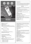
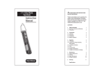
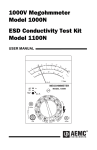
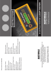
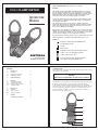
SAFETY INFORMATION: Always read before proceeding.
WARNING
CM54 CLAMP METER
This manual contains both information and warnings that are necessary for
the safe operation and maintenance of the clampmeter. It is recommended
that you read the instructions carefully and ensure that the contents are fully
understood. Failure to understand and to comply with the warnings and
instructions can result in serious injury, damage or even death.
INSTRUCTION
MANUAL
In order to avoid the danger of electrical shock, it is important that proper
safety measures are taken when working with voltages exceeding 30V AC
rms, 42V AC peak or 60V DC.
The clampmeter must only be used under the conditions and for the
purposes for which it has been constructed. Particular attention should be
paid to these warnings, the precautions, the technical specifications and
the use of the CM54 in dry surroundings.
Always inspect your clampmeter, test leads and accessories for any sign of
damage before use. If any abnormal conditions exist (e.g: broken test leads,
cracked case, display not reading, etc.), do not attempt to use it. Do not
expose it to direct sunlight, excessive temperature or moisture.
Keep this instruction manual for future reference. Updated instructions and
product information are available at: www.martindale-electric.co.uk
SYMBOLS:
Equipment complies with relevant EU Directives
AC (Alternating Current)
Ground
Direct Current
Equipment protected by Double Insulation (Class II)
Caution - refer to accompanying documents
MARTINDALE
Caution - risk of electric shock
End of life disposal of this equipment should be
in accordance with relevant EU Directives
ELECTRIC
Trusted by professionals
CONTENTS
1
1.1
1.2
1.3
Introduction
Description
Unpacking & Inspection
Replacing the Battery
1. INTRODUCTION
This manual contains information and warnings which must be followed to ensure
safe operation of the clampmeter.
2
2
4
4
2
Safety Information
5
3
3.1
3.2
3.3
3.4
Operation
Voltage Measurement
Current Measurement
Resistance Measurement
Continuity Testing
5
5
6
7
8
4
4.1
4.2
4.3
Maintenance
Cleaning
Repair & Service
Storage Conditions
9
9
9
9
5
Warranty
9
Technical Specification
10
WARNING
READ "SAFETY INFORMATION" BEFORE USING THE METER
1.1 Description
This clampmeter is a handheld 2000-count instrument that is designed for use in
the laboratory, field servicing, and any circumstance where high current
measurement is required. The clampmeter incorporates a finger guard which
ensures the safety of the user whilst operating the instrument, a rugged case that
is shock resistant and fire retardant, and electronic overload protection for all
functions and ranges. In addition, a protective carrying case is included for
protection of the meter whilst not in use.
8
7
9
5
6
4
3
1
2
1
2
1.2 Unpacking and Inspection
1. Volt - Input Terminal
This is the positive input terminal for VOLT measurements. Connection is
made to it using the red test lead.
Before unpacking the clampmeter, examine the shipping carton for any sign of
damage. Unpack and inspect the clampmeter and any associated leads for
damage. If there is any damage then consult your distributor immediately.
2. COM - Common Terminal
This is the negative (Ground) input terminal for all measurement modes
except current. Connection is made to it using the black test lead.
After removing your new Digital Clamp Meter (DCM) from its packaging, you
should have the following items:
3. Ω Ohms input terminal
This is the positive input terminal for resistance and continuity
measurements. Connection is made to it using the red test lead.
1. Digital clampmeter
2. Test lead set (one black, one red)
3. 9-Volt battery (installed in meter)
4. Instruction manual
5. Protective carry case
4. Display
The display indicates the measured value of signal, function mode,
low battery, range, max & hold settings.
If any of the above items are missing or are received damaged, please contact
the distributor from whom you purchased the unit.
5. Function / Range selector rotary switch.
The rotary switch selects the function and desired range.
1.3 REPLACING THE BATTERY
6. Max - Maximum recording mode
This function is used to measure the maximum value of AC/DC voltage,
AC/DC current and resistance.
WARNING
To avoid electrical shock, disconnect the test leads and any input signals
before replacing the battery. Replace only with same type of battery.
7. Hold Button
Freezes the last reading displayed.
8. Clamp Jaws
Detect AC current flowing through the conductor on test.
This meter is powered by a NEDA type 1604 or equivalent 9-volt battery. When
the meter shows the " " sign the battery must be replaced to maintain proper
operation. Follow the procedure below to replace the battery.
9. Trigger
Press the lever to open the clamp jaws. When the lever is released,
the jaws will close.
1. Disconnect the test leads from any live source, turn the rotary switch to off
and remove the test leads from the input terminals.
2. The battery cover is secured to the bottom case by a screw. Using a Phillips
head screwdriver, remove the screw and then remove the battery cover.
3. Replace the battery with a new equivalent 9-volt one observing correct polarity.
4. Replace the battery cover and re-install the screw.
3
4
2. SAFETY INFORMATION
4. Plug the red test lead into the VOLT input jack on the meter and connect to the
circuit where a voltage measurement is required. Voltage is always measured in
parallel across a test point.
The instrument complies with class II overvoltage CAT III 1000V of the
IEC1010-1 (EN61010-1) ; UL3111-1; and CAN/CSA C22.2 #1010.1-92
standards, pollution degree 2 in accordance with IEC-664 indoor use. If the
equipment is used in a manner not specified, the protection provided by the
equipment may be impaired.
5. Energise the circuit or device under test and make the voltage measurements.
Reduce the range setting, if set too high, until a satisfactory best resolution
reading is obtained.
This product complies with the requirements of the following European
Community Directives: 89/336/EEC (Electromagnetic Compatibility) and
73/23/EEC (Low Voltage) as amended by 93/68/EEC (CE Marking).
6. After completing the measurement, turn off the power to the circuit / device
under test, discharge all capacitors and disconnect the meter test leads.
Electrical noise or intense electromagnetic fields in the vicinity of the equipment
may disturb the measurement circuit. Measuring instruments will also respond to
unwanted signals that may be present within the measurement circuit. Users
should exercise care and take appropriate precautions to avoid misleading
results when taking measurements in the presence of electromagnetic
interference.
3.2 CURRENT MEASUREMENTS
WARNING
The clamp jaws are designed to take current measurements on
circuits with a maximum voltage difference of 500VAC between any
conductor and ground potential. Using the clamp jaws for current
measurements on circuits above this voltage may cause electric
shock, instrument damage and / or damage to the equipment under
test. Before measuring current, make sure that the test leads are
removed from the instrument.
3. OPERATION
3.1 VOLTAGE MEASUREMENTS
1. Turn off power to the circuit/device under test and discharge all capacitors.
The clamp jaws are overload protected up to 500VAC for up to 1
minute. Do not take current readings on circuits where the maximum
current potential is not known. Do not exceed the maximum current
that the instrument is designed to measure.
2. Plug the black test lead into the COM input jack on the meter and connect the
test lead tip to a grounded point (the reference point for measured voltage).
3. Select the desired AC voltage range (V ), or DC voltage range (V ). If the
magnitude of the voltage to be measured is unknown, always start with the
highest range.
1. Set function switch to ACA 1000A range.
WARNING
2. Press the trigger to open the clamp jaws and clamp them around a conductor.
The jaws should be completely closed before taking a reading.
To avoid possible electric shock, instrument damage and / or
equipment damage, do not attempt to take any voltage measurements
if the voltage is above 1000V DC or 750VAC. These are the maximum
voltages that this instrument is designed to measure. The "COM"
terminal potential should not exceed 500V measured to ground.
3. The most accurate reading will be obtained by keeping the conductor across
the centre of the clamp jaws.
5
6
4. The reading will be indicated on the display.
4. Connect the black & red test probe tips to the circuit or device under test,
making sure it is de-energised first.
5. Reduce the range if set too high until a satisfactory best resolution
reading is obtained.
5. Open circuits will be displayed as an overload condition.
6. Test lead resistance can affect low resistance measurements and should be
subtracted from resistance measurements for accuracy. Select the lowest
resistance range and short the test leads together. The value displayed is the test
lead resistance, which should subtracted from the resistance measurement.
Max - Maximum recording mode
This function is used to measure the maximum value of AC/DC voltage, AC/DC
current and resistance. To use this function, select the function and range then
press the MAX button. When this is done the "MAX" indicator will appear on the
display. When the instrument detects a signal, the maximum "MAX" value will be
displayed and held in the internal memory. To cancel the function, press the MAX
button once again.
7. After completing the measurement, disconnect the test leads.
Note when using 2000MΩ Range
The 2000MΩ range has a fixed 10-count offset in the reading. When the test
leads are shorted together in this range, the meter will display 010. This residual
reading must be subtracted from the measured resistance when this range is
used. For example, when measuring 1500MΩ on the 2000MΩ range, the display
will read 1510, from which the residual reading of 10 must be subtracted to obtain
the actual resistance of 1500MΩ.
Hold Button
Press (HOLD) to toggle in and out of data hold mode. In the data hold mode, the
"HOLD" indicator is displayed and the last reading is frozen on the display. Press
the (HOLD) button again to exit and resume taking readings.
3.3 RESISTANCE MEASUREMENTS
3.4 CONTINUITY TESTING
WARNING
Attempting resistance or continuity measurements on live circuits can
cause electrical shock, damage to the instrument and damage to the
equipment under test. Resistance measurements must be made on
de-energised (DEAD) circuits only, for maximum personal safety. The
electronic overload protection installed in this instrument will reduce
the possibility of damage to the instrument but not necessarily avoid
all damage or shock hazards.
1. Select the (
) position by turning the rotary selector switch.
2. Follow steps 2 & 4 as for resistance measurements
3. The clampmeter emits a tone when measuring resistance of approximately
75Ω or less. After measurements have been carried out, disconnect the test
leads from the circuit and from the input terminals of the clampmeter.
1. Isolate any power which may be present at the resistance to be measured and
discharge any capacitors. Any voltage that may be present during a resistance
measurement will cause inaccurate readings and could damage the meter if the
voltage exceeds the overload protection of 500V DC or AC.
2. Insert the black & red test leads into the COM and Ω input terminals
respectively.
3. Select the desired ohms (Ω) range.
7
8
4. MAINTENANCE
Specification
CM54 Clamp Meter
Maintenance consists of periodic cleaning and battery replacement.
Repairs or servicing not covered in this manual should only be
performed by qualified personnel.
4.1 Cleaning
The CM54 may be cleaned using a soft dry cloth. Do not use abrasives, solvents,
or detergents, which can be conductive.
4.2 Repair & Service
There are no user serviceable parts in this unit. Return to Martindale Electric
Company Ltd if faulty. Our service department will quote promptly to repair any
fault that occurs outside the guarantee period.
Display: 3½ digit 21mm large LCD, maximum reading 1999 with function and units
sign annunciators.
Polarity: Automatic, positive implied, negative indicated.
Before the unit is returned, please ensure that you have checked the unit and
associated leads thoroughly for flat batteries (check & replace), blown fuses
(check & replace) and other poor connections.
Over Range Indication: (OL) is displayed.
4.3 Storage Conditions
The clampmeter should be kept in warm dry conditions away from direct sources
of heat or sunlight, and in such a manner as to preserve the working life of the
unit. It is strongly advised that the unit is not kept in a tool box where other tools
may damage it.
Low Battery Indication: The "
below accurate operating level.
" is displayed when the battery voltage drops
Display Update Rate: 2.5 per second, nominal
Operating Environment: 0°C to 50°C at <70% Relative Humidity.
Storage Environment: -20°C to 60°C at <80% Relative Humidity with battery
removed from meter.
5. WARRANTY
The CM54 is guaranteed against faults in manufacture and materials for 24
months from date of invoice and will be rectified by us free of charge, provided
the unit has not been tampered with and is returned to us with its housing
unopened. Damage due to dropping, abuse or misuse is not covered by this
guarantee. Batteries and fuses are not covered by this guarantee.
Temperature Coefficient: 0.1 X (specified accuracy) / °C (<18°C or >28°C)
Altitude: 2000M max
Power: Standard 9-volt battery, NEDA 1604, IEC 6F22, JIS 006P, PP3
Battery Life: 300 hours typical with alkaline battery.
Jaw Opening Capability: 57mm conductor, 70 X 18mm bus bar.
Size (H x W x D): 189 x 87 x 37mm
Weight: Approx. 540grams (including battery)
* Accuracy is given as ± ([% of reading]+[number of least significant digits])
at 18°C to 28°C with relative humidity up to 70%.
9
Continuity Test
Other products from Martindale:
Audible Threshold
Open Circuit Volts
Response Time
G 16th Edition Testers
G Non-trip Loop Testers
G All-in-one’s
G PAT Testers & accessories
G Calibration Equipment
G Phase Rotation Units
G Continuity Testers
G Proving Units
G Electrician’s Kits
G Socket Testers
G Full Calibration & Repair Service
G Thermometers & Probes
G Fuse Finders
G Test Leads
G Digital Clamp Meters
G Voltage Indicators
Overload protection: 1000VDC / 750V AC RMS
G Digital Multimeters
G Specialist Metrohm Testers (4 & 5kV)
AC Volts (Average sensing RMS indicating)
G Microwave Leakage Detectors
G Specialist Drummond Testers
Less than 75Ω
~
~500msec
3.0Vdc typical
Overload Protection: 500v DC or AC rms
DC Volts
Range
1000V
Resolution
1V
Accuracy
±(0.5% rdg +1d)
Input Impedance
10MΩ
Range
Resolution
Accuracy
Input Impedance
750V
1V
±(1.5% rdg +4d)
4.5MΩ
G Motor Maintenance Equipment
Frequency Response: 50Hz to 500Hz
Overload protection: 1000VDC or 750V AC RMS
AC Current (Average sensing RMS indicating)
Range
Resolution
200A
100mA
1000A
1A
Accuracy
0-600A±(1.5% rdg+5d)50-60Hz
>600A±(2.0% rdg+5d)50-60Hz
0-600A±(3.0%rdg+5d)61-400Hz
>600A±(3.5%rdg+5d)61-400Hz
Overload Protection: 1200A for 60 seconds Maximum
Resistance
Range
Resolution
Accuracy
Open Circuit Volts
200Ω
20kΩ
20MΩ
2000MΩ
0.1Ω
10Ω
10kΩ
1000kΩ
±(1.2% rdg+4d)
±(1.0% rdg+3d)
±(2.0% rdg+5d)
±(5% rdg+10d)
3.0Vdc
0.3Vdc
0.3Vdc
3.0Vdc
Overload Protection: 500v DC or AC RMS
Martindale Electric Company Limited
Metrohm House, Penfold Trading Estate, Imperial Way, Watford, WD24 4YY, UK.
Tel: +44(0)1923 441717 Fax: +44 (0)1923 446900
E-mail: [email protected]
Website: www.martindale-electric.co.uk
© Martindale Electric Company Ltd. 1997 - 2006
Registered in England No. 3387451. Rev 4