1
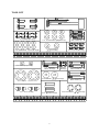
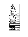
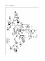
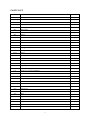
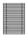
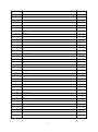
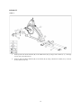
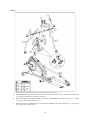
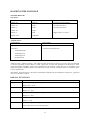
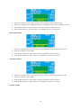
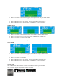
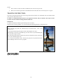
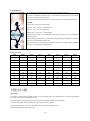
USER MANUAL – EN IN 9118 Elliptical inSPORTline ET520i Made in P.R.C 1 CONTENTS SAFETY CAUTION............................................................................................................................................... 3 TOOL KIT .............................................................................................................................................................. 4 EXPLODED VIEW ................................................................................................................................................ 6 PARTS LIST ........................................................................................................................................................... 7 ASSEMBLY ......................................................................................................................................................... 11 KNOWING THE ICONSOLE .............................................................................................................................. 21 TRAINING INSTRUCTION ................................................................................................................................ 25 TERMS AND CONDITIONS OF WARRANTY, WARRANTY CLAIMS ....................................................... 27 2 PREFACE This elliptical has been designed and constructed to provide maximum safety. Nevertheless, certain precautions should be taken when using exercise equipment. Read the whole manual before assembling and using the bicycle. The following safety precautions should also be observed: SAFETY CAUTION 1. Before using the elliptical, please read all instructions in this manual. 2. It is the responsibility of the owner to ensure that all users of the elliptical are adequately informed of all precautions. Use the elliptical only as described in this manual. 3. Use the elliptical indoors on a level surface and keep it away from moisture and dust. Place a mat under the stabilizers to protect the carpet or floor. 4. Inspect and tighten all parts regularly. Replace and worm parts immediately. 5. Keep children away from this equipment at all times. DO NOT leave them unsupervised in the room where this exerciser is kept. 6. Wear appropriate exercise clothing when using the elliptical. Do not wear loose clothing that could become caught in the elliptical. 7. If you feel pain or dizziness while exercising, stop immediately and cool down. 8. The pulse sensor is not a medical device. Various factors including the user’s movement, may affect the accuracy of the heart rate readings. The Pulse sensor is intended only as an exercise aid in determining heart rate trends in general. 3 IMFD TOOL KIT Allen Key(1) Box Spanner(1) F-2:HexboltM8*P1.0*20L(4) F-13:SCREW M5*12L(8) F-5: Curved Washer 8* 19*2T (6) F-7:Flat washer for 8* 19*2T bolt(2) F-14: FlatWasher Ł p 6*Ł p 16*1T(8) F-6:Carriage Bolt M8*P1.25*40L (4) F-4;lock nut for M8 bolt (6) IMFD F-9;FlatWasher £p 8*£p 16*1T(2) F-11; Allen bolt M8*P1.25*50L(2) F-1;FlatWasher 8* 25*2T bolt(4) F-15ˇG ˇ2 ] ˇ^ F-19ˇFAcorn nut M8(4) F-10; 16*36.5L bolt(2) 4 F-12: SCREW M5*8L(4) F-8:Carriage Bolt M8*P1.25*55L (2) F-20:Carriage Bolt M8*P1.25*65L (2) F-3:Curved Washer 20* 30*0.3T(2) 1 1 1/1 1/1 1/1 1/1 1/1 IMFD IMFD A llen Key(1) Box Spanner(1) 1/1 Ł p Ł p F-11; Al l en bol t M8*P1.25*5 0L(2) F-1; 8* 25*2T bol t( 4) F-8:Carri age Bol t M8*P1.25* 55L ( 2) F-18:Carri age Bol t M8*P1.25* 60L (2) ˇGˇ] ˇ^ Curved Washer F-6:Carri age Bol t M8*P1.25*40L (4) F-19 ˇFAcorn nut M8(4) F-10; Ł p Ł p 16*36.5L bolt( 2) F-3:Curved Washer 20* 30*0.3T( 2) F-4; l ock nut for M8 bolt ( 6) 1/1 1/1 5 EXPLODED VIEW 6 PARTS LIST NO. DESCRIPTION Q'TY Computer 1 Screw 4 Handlebar post set 1 (set) B-1 End cap for front handlebar 2 B-2 Foam grip for front handlebar 2 B-3 Hand pulse 2 B-4 Screw 2 B-5 Sleeve 2 B-6 Axle for handlebar 1 B-7 Flat washer 4 B-8 Semicircle washer 2 B-9 Cable wire (upper) 1 B-10 Spring washer 6 B-11 Screw 6 B-12 Screw 2 B-13 Hand pulse wire 2 B-14 Screw 2 B-15 Cover for handlebar post 1 C-L Left upper handlebar 1 (set) C-R Right upper handlebar 1 (set) C-1 End cap for upper handlebar 2 C-2 Foam grip for upper handlebar 2 Main frame 1 (set) D-1 Cable wire (lower) 1 D-2 C-type ring 1 D-3 Flat washer 1 D-4 Wave washer 1 D-5 Screw for sensor box 1 D-6 Sensor box 1 D-7 Bearing 2 D-8 Belt 1 D-9 Screw 7 D-10 Chain cover (L) 1 D-11 Screw 4 D-12 Nut 2 D-13 Chain cover (R) 1 A A-1 B D 7 D-14 DC Wire 1 D-15 Adaptor 1 D-16 Brake knob 1 D-17 Nut 2 D-18 Axle for brake 1 D-19 Nut 2 D-20 Nylon nut 2 D-21 Flat washer 2 D-22 Screw 1 D-23 Flat washer 2 D-24 Nylon nut 1 D-25 Brake plate 1 D-26 Felt 1 D-27 Motor bracket 1 (set) D-29 Axle of gear box 1 D-30 Screw 1 D-31 Nut 1 Eddy magnet assembly 1 (set) E-1 Screw 2 E-2 Flat washer 2 E-3 Spring washer 2 Screw set 1 (set) F-1 Flat washer 4 F-2 Nylon screw 4 F-3 Wave washer 2 F-4 Nylon nut 6 F-5 Semicircle washer 6 F-6 Carriage screw 4 F-7 Flat washer 2 F-8 Carriage screw 2 F-9 Flat washer 2 F-10 Bushing 2 F-11 Screw 2 F-12 Screw 4 F-13 Screw 8 F-14 Flat washer 8 F-15 Cover for screw 2 F-16 Bushing wrench 1 E F 8 F-17 Hex wrench 1 F-19 Nut 4 F-20 Screw 2 Flywheel set 1 (set) G-1 Flywheel 1 G-2 Nut 2 G-3 Nut 3 G-4 Flat washer 1 G-5 Bearing 1 G-6 Axle for flywheel 1 G-7 Bearing 1 (set) G-8 Bushing 1 Front stabilizer set 1 (set) H-1 Foot cap for front stabilizer 2 H-2 Nut 2 H-3 C-type ring 2 H-4 Transportation wheel 2 H-5 Bushing 2 H-6 Screw 4 H-7 Adjustable foot cap 2 I-L Left pedal arm 1 (set) I-R Right pedal arm 1 (set) I-1 Sleeve 4 I-2 End cap 2 I-4 Pedal connector 2 I-5 Flat washer 6 I-6 Screw 6 Idler 1 (set) J-1 Hex. screw 1 J-2 Nylon nut 1 J-3 Flat washer 1 J-4 Spring 1 J-5 Spring bracket 1 J-6 Hex. screw 1 J-7 Flat washer 1 J-8 Hex. screw 1 J-9 Idler wheel 1 K-L Left lower handlebar 1 (set) G H J 9 K-R Right lower handlebar 1 (set) K-1 Screw 4 K-2 Sleeve 4 L-L Left crank arm 1 L-R Right crank arm 1 L-1 Screw 4 L-2 Flat washer 4 L-3 Fixed stick for wheel 2 L-4 Wheel 2 L-5 Bearing 4 L-6 Cover for wheel 2 L-7 Screw 4 L-8 Bushing 4 L-9 Wave washer 2 L-10 Nylon nut 2 L-11 Flat Washer 4 L-12 Bearing 4 L-13 Bushing 2 L-14 Hex. screw 2 L-15 Crank arm connect base 2 Linkage tube of rear stabilizer set 1 (set) M-1 Linkage tube of rear stabilizer 2 M-2 Linkage sleeve of rear stabilizer 4 M-3 Fixed axle of folder 2 M-4 Foot cap 2 M-5 Screw 4 M-6 Left end cap 1 M-7 Right end cap 1 Axle set 1 (set) N-1 Pulley 1 N-2 Axle 1 N-3 Hex. screw 3 N-4 Bushing 1 Disc cover and crank set 2 (set) O-1 Crank (R+L) 2 O-2 Screw 10 O-3 Screw 2 M N O 10 O-4 Cover for disc cover 2 O-5 Disc cover 2 P-1 Front cover for upper handlebar 2 P-2 Rear cover for upper handlebar 2 P-3 Left cover for pedal arm 2 P-4 Right cover for pedal arm 2 P-5 Pedal 2 Rear stabilizer set 1 (set) Q-1 End cap 2 Q-2 Screw 4 Q-3 Rear stabilizer 1 Q-4 Foot cap 2 Q-5 Nut 2 Q ASSEMBLY BEFORE EVERYTHING It will affect your safety and the smoothness of this machine, as well as its life time. Please check is there’s any parts missed. Please assemble all the screws first After everything fixed, then make sure they’re firmly enough. 11 BUILD IT STEP 1 1. Securely fasten the Front stabilizer (H) to the Main frame (D) by using 2 Flat washers (F-7), 2 Carriage screws (F-8), and 2 Nut (F-19). 2. Securely fasten the Rear stabilizer (M) to the Frame (D) by using 2 Semicircle washer (F-5), 2 Screws (F-20), and 2 Nut (F-19). 12 STEP 2 1. Assemble the Left crank arm (L-L) to the Crank (O-1) by using 1 Flat washer (F-1), 1 Nylon screw (F2), and 1 Cover for screw (F-15). 2. Assemble the Right crank arm (L-R) to the Crank (O-1) by using 1 Flat washer (F-1), 1 Nylon screw (F2), and 1 Cover for screw (F-15). 13 STEP 3 1. Connect the Cable wire (upper) (B-9) to the Cable wire (lower) (D-1). 2. Install the Handlebar post set (B) to the main frame with 4 Flat washers (B-7), 2 Semicircle washers (B8), 6 Spring washers (B-10), and 6 Screws (B-11). 3. Install the Right lower handlebar (K-R) to the Axle for handlebar with 1 Flat washer (F-1), 1 Nylon screw (F-2), and 1 Wave washer (F-3). 4. Install the Left lower handlebar (K-L) to the Axle for handlebar with 1 Flat washer (F-1), 1 Nylon screw (F-2), and 1 Wave washer (F-3). 14 STEP 4 1. Attach the Left pedal arm (I-L) to the left crank arm, and then fasten it with 1 Pedal connector (I-4), 3 Flat washers (I-5), and 3 Screws (I-6). 2. Attach the Right pedal arm (I-R) to the right crank arm, and then fasten it with1 Pedal connector (I-4), 3 Flat washers (I-5), and 3 Screws (I-6). 3. Assemble the Left pedal arm (I-L) to the Lower handlebar (K-L) by using 1 Nylon nut (F-4), 1 Flat washer (F-9), 1 Sleeve (F-10). 4. Assemble the Right pedal arm (I-R) to the Lower handlebar (K-R) by using 1 Nylon nut (F-4), 1 Flat washer (F-9), 1 Sleeve (F-10). 15 STEP 5 Assemble the Pedals (P-5) with 8 Screws (F-13) and 8 Flat washers (F-14). 16 STEP 6 Assemble Left cover for pedal arms (P-3) and Right cover for pedal arms (P-4) with Screws (F-12). 17 STEP 7 1. Install the Left upper handlebar (C-L) to the Left lower handlebar (K-L) by using 4 Nylon nuts (F-4), 4 Semicircle washers (F-5), and 4 Carriage screws (F-6). 2. Install the Right upper handlebar (C-R) to the Right lower handlebar (K-R) by using 4 Nylon nuts (F-4), 4 Semicircle washers (F-5), and 4 Carriage screws (F-6). 3. Put the Front cover for upper handlebars (P-1) and Rear cover for upper handlebars (P-2) to the Right/Left upper handlebars and fasten them with 4 Screws (K-1). 18 STEP 8 1. Plug the Cable wire (upper) (B-9) and Hand pulse wire (B-13) onto the back of Computer (A). 2. Install the Computer (A) to the computer panel which is welded on the top of the handlebar post. Fix the computer with 4 screws (A-1). 19 FOLD FOR STORAGE & UNFOLD FOR USE 10 1 2 A B A B C 1. Make the two arrow icons of chain cover and disc to be alignment. 2. Tighten the knob by clockwise way. 3. Lift up linkage tube of rear stabilizer. 4. Fix the shaft into the hole, fold for storage. 5. Unfold for use- to do the reverse of what above steps. 20 C KNOWING THE ICONSOLE SUPPORT DEVICES iOS devices: iPhone iPad iPod . iPhone 5S . iPad Air . iPod touch (5th generation) . iPhone 5C . iPad 4 . iPod (4th generation) . iPhone 5 . iPad 3 . iPod (3rd generation) . iPhone 4S . iPad 2 . iPhone 4 . iPad . iPhone 3GS . iPad Mini . Support iOS 5.0 or above Android devices: Android phone Android tablet . OS 2.2 or above . OS 4.0 or above . resolution: . resolution 1280x800 pixels 1920x1080 pixels 1280x800 pixels 1280x760 pixels 800x480 pixels “Made for iPod,” “Made for iPhone,” and “Made for iPad” mean that an electronic accessory has been designed to connect specifically to iPod, iPhone, or iPad, respectively, and has been certified by the developer to meet Apple performance standards. Apple is not responsible for the operation of this device or its compliance with safety and regulatory standards. Please note that the use of this accessory with iPod, iPhone, or iPad may affect wireless performance. iPad, iPhone, iPod, iPod classic, iPod nano, iPod shuffle, and iPod touch are trademarks of Apple Inc., registered in the U.S. and other countries. DISPLAY FUNCTIONS ITEM DESCRIPTION TIME Workout time displayed during exercise. Range 0:00 ~ 99:59 SPEED Workout speed displayed during exercise. Range 0.0 ~ 99.9 DISTANCE Workout distance displayed during exercise. Range 0.0 ~ 99.9 CALORIES Burned calories during workout display. Range 0 ~ 999 PULSE Pulse bpm displayed during exercise. Pulse alarm when over preset target pulse. 21 RPM Rotation per minute Range 0 ~ 999 WATT Workout power consumption In Watt Program mode, computer will remain preset watt value (setting range 0~350) MANUAL Manual mode workout. PROGRAM Beginner, Advance, and Sporty PROGRAM selection. CARDIO Target HR training mode. KEYS ITEM DESCRIPTION Increase resistance level Setting selection. Decrease resistance level Setting selection. Confirm setting or selection. Hold on pressing for 2 seconds, computer will reboot and start from user setting. Reverse to main menu during presetting workout value or stop mode. Start/ Stop Start or Stop workout. Recovery Test heart rate recovery status. Body fat Test body fat% and BMI. Up Down Mode Reset OPERATION POWER ON Plug in power supply, computer will power on and display all segments on LCD for 2 seconds. After 4 minutes without pedaling or pulse input, console will enter into power saving mode. Press any key may wake the console up. WORKOUT SELECTION Press UP and Down to select workout Manual Beginner Advance Sporty Cardio Watt MANUAL MODE Press START in main menu may start workout in manual mode. 22 1) Press UP or DOWN to select workout program, choose Manual and press Mode to enter. 2) Press UP or DOWN to preset TIME, DISTANCE, CALORIES, PULSE and press MODE to confirm. 3) Press START/STOP keys to start workout. Press UP or DOWN to adjust load level. 4) Press START/STOP keys to pause workout. Press RESET to reverse to main menu. BEGINNER MODE 1) Press UP or DOWN to select workout program, choose Beginner mode and press Mode to enter. 2) Press UP or DOWN to preset TIME. 3) Press START/STOP key to start workout. Press UP or DOWN to adjust load level. 4) Press START/STOP key to pause workout. Press RESET to reverse to main menu. ADVANCE MODE 1) Press UP or DOWN to select workout program, choose Advance mode and press Mode to enter. 2) Press UP or DOWN to preset TIME. 3) Press START/STOP key to start workout. Press UP or DOWN to adjust load level. 4) Press START/STOP key to pause workout. Press RESET to reverse to main menu. SPORTY MODE 23 1) Press UP or DOWN to select workout program, choose Sporty mode and press Mode to enter. 2) Press UP or DOWN to preset TIME. 3) Press START/STOP key to start workout. Press UP or DOWN to adjust load level. 4) Press START/STOP key to pause workout. Press RESET to reverse to main menu. CARDIO MODE 1) Press UP or DOWN to select workout program, choose H.R.C. and press Mode to enter. 2) Press UP or Down to select 55%.75%.90% or TAG (TARGET H.R.) (default: 100). 3) Press UP or DOWN to preset workout TIME. 4) Press START/STOP key to start or stop workout. Press RESET to reverse to main menu. WATT MODE 1) Press UP or DOWN to select workout program, choose WATT and press Mode to enter. 2) Press UP or DOWN to preset WATT target. (default: 120) 3) Press UP or DOWN to preset TIME. 4) Press START/STOP key to start workout. Press UP or DOWN to adjust Watt level. 5) Press START/STOP key to pause workout. Press RESET to reverse to main menu. iConsole+ APP Turn on Bluetooth on tablet, search for console device and press connect. (password: 0000) Turn on iconsole+ app on tablet, and start workout with tablet. 24 NOTE: 1. Once console is connect to tablet via Bluetooth, the console will power off. 2. Please exit iConsole app and turn off the Bluetooth from iPad, then the console will power on again. TRAINING INSTRUCTION If you have not been physically active for a long period of time and also to avoid health risks you should consult your physician before the exercise. To achieve a considerable improvement of your physical resistance and your health, some aspects of how to achieve the most efficient training should be followed: INTENSITY To achieve maximum results the right intensity has to be chosen. The heart rate is used as guideline. As a rule of thumb the following formula is commonly used: Maximum pulse rate = 220 – Age While exercising the pulse rate should always be between 60% - 85% of the maximum rate. For your personal training rates please see the attached pulse rate chart. When starting to exercise you should keep your rate at 70% of your maximum pulse rate in the first couple of weeks. With increasing improvement of fitness the pulse rate should be slowly increased to 85% of your maximum pulse rate. This is a personal orientation value. Consult your physician for professional advice before adapting a heart rate recovery program. 25 FAT BURNING The body starts to burn fat at approx. 65% of the maximum pulse rate. To reach an optimum at burning rate, it is advisable to keep the pulse rate between 70%-80% of the maximum pulse rate. The optimum training amount consists of three workouts per week 30 minutes each. Example: One 52 years of age to start exercising. Max rate = 220 - 52(age) = 168 pulse/min. Min rate = 168 * 0.7 = 117 pulse/min. Highest rate = 168 * 0.85 = 143 pulse/min. During the first weeks it is recommend to start with a pulse rate of 117, afterwards increase it to 143. With increasing improvement of fitness the training Intensity should be increased to 70%-85% of your maximum pulse rate. This can be done by increasing the pedaling resistance, by suing a higher paddling frequency or with longer training periods. Pulse rate chart: AGE MAX 60% 65% 70% 75% 80% 85% 20 200 120 130 140 150 160 170 25 195 117 127 137 146 156 166 30 190 114 124 133 143 152 162 35 185 111 120 130 139 148 157 40 180 108 117 126 135 144 153 45 175 105 114 123 131 140 149 50 170 102 111 119 128 136 145 55 165 99 107 116 124 132 140 60 160 96 104 112 120 128 136 65 155 93 101 109 116 124 132 70 150 90 98 105 113 110 128 SUCCESS Even after a short period of regular exercises you will realize that you constantly have to increase the pedaling resistance to reach your optimum pulse rate. The units will be continuously easier and you will feel a lot fitter during your normal day. For this achievement you should motivate yourself to exercise regularly. Choose fixed hours for your work out and do not start training too aggressively. And old saying amongst sportsmen says: 26 “The most difficult thing about training is to start it.” Wishing you lots of fun and success with your exerciser. TERMS AND CONDITIONS OF WARRANTY, WARRANTY CLAIMS General Conditions of Warranty and Definition of Terms All Warranty Conditions stated hereunder determine Warranty Coverage and Warranty Claim Procedure. Conditions of Warranty and Warranty Claims are governed by Act No. 40/1964 Coll. Civil Code, Act No. 513/1991 Coll., Commercial Code, and Act No. 634/1992 Coll., Consumer Protection Act, as amended, also in cases that are not specified by these Warranty rules. The seller is SEVEN SPORT s.r.o. with its registered office in Borivojova Street 35/878, Prague 13000, Company Registration Number: 26847264, registered in the Trade Register at Regional Court in Prague, Section C, Insert No. 116888. According to valid legal regulations it depends whether the Buyer is the End Customer or not. “The Buyer who is the End Customer” or simply the “End Customer” is the legal entity that does not conclude and execute the Contract in order to run or promote his own trade or business activities. “The Buyer who is not the End Customer” is a Businessman that buys Goods or uses services for the purpose of using the Goods or services for his own business activities. The Buyer conforms to the General Purchase Agreement and business conditions to the extent specified in the Commercial Code. These Conditions of Warranty and Warranty Claims are an integral part of every Purchase Agreement made between the Seller and the Buyer. All Warranty Conditions are valid and binding, unless otherwise specified in the Purchase Agreement, in the Amendment to this Contract or in another written agreement. Warranty Conditions Warranty Period The Seller provides the Buyer a 24 months Warranty for Goods Quality, unless otherwise specified in the Certificate of Warranty, Invoice, Bill of Delivery or other documents related to the Goods. The legal warranty period provided to the Consumer is not affected. By the Warranty for Goods Quality, the Seller guarantees that the delivered Goods shall be, for a certain period of time, suitable for regular or contracted use, and that the Goods shall maintain its regular or contracted features. The Warranty does not cover defects resulting from: User’s fault, i.e. product damage caused by unqualified repair work, improper assembly, insufficient insertion of seat post into frame, insufficient tightening of pedals and cranks Improper maintenance Mechanical damages Regular use (e.g. wearing out of rubber and plastic parts, joints etc.) 27 Unavoidable event, natural disaster Adjustments made by unqualified person Improper maintenance, improper placement, damages caused by low or high temperature, water, inappropriate pressure, shocks, intentional changes in design or construction etc. Warranty Claim Procedure The Buyer is obliged to check the Goods delivered by the Seller immediately after taking the responsibility for the Goods and its damages, i.e. immediately after its delivery. The Buyer must check the Goods so that he discovers all the defects that can be discovered by such check. When making a Warranty Claim the Buyer is obliged, on request of the Seller, to prove the purchase and validity of the claim by the Invoice or Bill of Delivery that includes the product’s serial number, or eventually by the documents without the serial number. If the Buyer does not prove the validity of the Warranty Claim by these documents, the Seller has the right to reject the Warranty Claim. If the Buyer gives notice of a defect that is not covered by the Warranty (e.g. in the case that the Warranty Conditions were not fulfilled or in the case of reporting the defect by mistake etc.), the Seller is eligible to require a compensation for all the costs arising from the repair. The cost shall be calculated according to the valid price list of services and transport costs. If the Seller finds out (by testing) that the product is not damaged, the Warranty Claim is not accepted. The Seller reserves the right to claim a compensation for costs arising from the false Warranty Claim. In case the Buyer makes a claim about the Goods that is legally covered by the Warranty provided by the Seller, the Seller shall fix the reported defects by means of repair or by the exchange of the damaged part or product for a new one. Based on the agreement of the Buyer, the Seller has the right to exchange the defected Goods for a fully compatible Goods of the same or better technical characteristics. The Seller is entitled to choose the form of the Warranty Claim Procedures described in this paragraph. The Seller shall settle the Warranty Claim within 30 days after the delivery of the defective Goods, unless a longer period has been agreed upon. The day when the repaired or exchanged Goods is handed over to the Buyer is considered to be the day of the Warranty Claim settlement. When the Seller is not able to settle the Warranty Claim within the agreed period due to the specific nature of the Goods defect, he and the Buyer shall make an agreement about an alternative solution. In case such agreement is not made, the Seller is obliged to provide the Buyer with a financial compensation in the form of a refund. SEVEN SPORT, s.r.o. Borivojova 35/878 130 00 Praha 3, Czech Rebublic CRN: 268 47 264, VAT ID: CZ26847264 Orders: +420 556 300 970, [email protected] Warranty Claims: +420 556 770 190, Mobile: +420 604 853 019, [email protected] Service: +420 556 770 190, Mobile: +420 604 853 019, [email protected] Fax: +420 556 770 192, (Service +420 556 770 191) Web: www.insportline.cz, www.worker.cz, www.worker-moto.cz INSPORTLINE, s.r.o. Bratislavska 36, 911 05 Trencin, Slovakia CRN: 36311723, VAT ID: SK2020177082 Orders: +421(0)326 526 701, +421(0)917 649 192, [email protected] Warranty Claims: +421(0)326 526 701, +421(0)918 408 519, [email protected] Fax: +421(0)326 526 705 28 Web: www.insportline.sk, www.worker.sk, www.worker-moto.sk Date of Sale: Stamp and Signature of Seller: 29