1
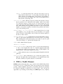
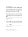
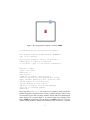
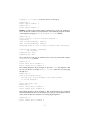
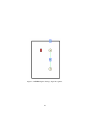
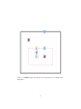
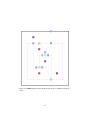
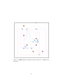
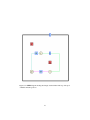
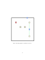
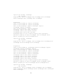
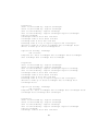
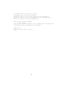
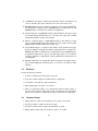
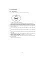
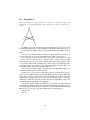
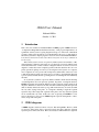
CDEG User’s Manual
Nathaniel Miller
October 11, 2011
1
Introduction
This is the user’s manual for Nathaniel Miller’s CDEG program. CDEG stands for
“Computerized Diagrammatic Euclidean Geometry.” This program implements a diagrammatic formal system for giving diagram-based proofs of theorems of Euclidean
geometry similar to the informal proofs found in Euclid’s Elements [1]. The details of
the formal system this computer program is based on can be found in Nathaniel Miller’s
book, Euclid and his Twentieth Century Rivals: Diagrams in the Logic of Euclidean
Geometry [2].
This formal system is based on a precisely defined syntax and semantics of Euclidean diagrams. What does this mean? To say that it has a precisely defined syntax
means that all the rules of what constitutes a diagram and how we can move from one
diagram to another have been completely specified. The fact that these rules are completely specified is perhaps obvious if you are using the formal system on a computer,
since computers can only operate with such precisely defined rules. However, it was
commonly thought for many years that it was not possible to give Euclidean diagrams
a precise syntax, and that the rules governing the use of such diagrams were inherently
informal.
To say that the system has a precisely defined semantics means that the meaning
of each diagram has also been precisely specified. In general, one diagram drawn by
CDEG can actually represent many different possible collections of lines and circles in
the plane. What these collections all share, and share with the diagram that represents
them, is that they all have the same topology. This means that any one can be stretched
into any other, staying in the plane. So a diagram containing a single line segment
represents all possible single line segments in the plane, since any such line segment
can be stretched into any other. If this isn’t clear, try playing with CDEG for a bit,
and you should get a sense of how CDEG diagrams represent arrangements of lines,
circles, and points in the plane.
2
CDEG diagrams
A CDEG diagram contains two kinds of objects: dots and segments. The dots, which
are shown as light yellow circles, represent points in the plane, while the segments
represent pieces of lines and circles. There are actually two different kinds of segments
1
that can occur in a diagram: solid segments, which represent pieces of lines, and dotted
segments, which represent pieces of circles. The dots and segments of a diagram are
enclosed by a bold line called the frame. The dots and segments of a diagram, along
with the frame, break the diagram into a collection of regions. Every dot, segment,
region, and piece of the frame in a CDEG diagram is labeled with a number, so that we
can refer to it. Dots are labeled with a number inside the yellow circle; segments are
labeled with a number in a blue box along the segment, and regions are labeled with a
number in a red box somewhere in the middle of the region.
The segments in a diagram are part of diagrammatic lines and circles. Each line
and circle is assigned a different color, so that all of the segments that make up a given
line or circle with be the same color. In general, segments that are not part of the
same line or circle have different colors, although once there are a lot of different lines
and circles, the colors are assigned randomly, so occasionally different lines may have
similar colors. Lines may continue to the frame, in which case we consider them to
be infinite in that direction. Thus, infinite lines intersect the frame in two places, rays
intersect it in one place, and line segments don’t intersect it at all.
Just as with traditional informal geometric diagrams, pieces of CDEG diagrams
may be marked equal. Markers can mark line segments, angles, or areas in the diagram. Rather than being marked with slash marks on the diagram, as would be done
with some informal diagrams, the markings are printed as text along with the diagram.
(Representations that combine text with diagrams are sometimes referred to as heterogenous representations.) Line segments are represented by collections of solid line
segments; these are referred to as diagrammatic segments or dsegs. If n solid segments all intersect a dot d, then they divide the 360◦ around d into n different smallest
possible angles. We refer to these as primative angles, or pangles, and label them by
a pair of numbers (nd, ns), where nd is the number of the dot at the vertex, and ns
is the number of the segment on the counterclockwise side of the primitive angle. In
general, angles are represented in diagrams by collections of these primitive angles,
which we refer to as diagrammatic angles or di-angles. Finally, areas of the graph
are represented by collections of regions, which we refer to as region sets. Markers in
CDEG diagrams can mark dsegs, di-angles, or region sets to be equal to other dsegs,
di-angles, or region sets.
Each CDEG diagram represents all of the possible equivalent collections of points,
lines, and circles with the same topology as the diagram. However, it is often the case
that when we perform some geometric operation on a diagram, such as connecting two
points with a line, there may be multiple possible outcomes depending on which of
these equivalent collections you start with. CDEG allows for this possibility through
the use of diagram arrays. A diagram array is just a collection of several possible diagrams showing different possible outcomes. To distinguish them from diagram arrays,
we often refer to the single diagrams that make up the arrays as primitive diagrams, or
pds for short.
CDEG allows you to manipulate diagrams through the use of construction and
inference rules. These rules are meant to be sound. This means that if you start with a
diagram D that represents a collection C of points, lines, and circles in the plane, and
you apply a rule to D, then at least one of the diagrams in the resulting diagram array
should still represent C (or, in the case of a construction rule that added a line or circle
2
to the diagram, C with the appropriate line or circle added). For more details, see [2].
3
CDEG commands
CDEG is run through a text interface that appears in a terminal window. It also pops
up separate graphics windows to display diagrams. When you start CDEG running,
you start with a single primitive diagram that consists of the frame and a single, empty
region. We refer to this as the empty diagram. The prompt that CDEG displays,
CDEG(1/1)%, indicates that the current diagram is primitive diagram number 1 in
a a diagram array made up of 1 diagram. In general, the first number in this prompt
indicates which diagram number is the current primitive diagram that you are looking
at and working with, while the second number gives the total number of diagrams in
the array.
When inputting commands, CDEG generally just looks at the first letter of whatever you type to determine what command you intend to use. If you type ’h’, CDEG
will display a list of possible commands. In each case, the letter enclosed in angle
brackets is the letter you need to type to get the command.
Several commands require you to input dsegs, di-angles, or region sets. For dsegs
and region sets, you enter the numbers of the segments or regions that make them up
one at a time, and then enter zero to indicate that you are done. Di-angles can be
entered in two separate ways. Di-angles in which all of the primitive angles are next to
one another and share the same vertex can be entered using “<s>imple entry,” in
which the di-angle is specified by giving the vertex number followed by the numbers of
the segments on the counter-clockwise and clockwise sides of the angle. However, it is
sometimes necessary to input di-angles which the primitive angles are not next to one
another and may not even share the same vertex. In this case, `‘<a>dvanced entry”
is available, in which all of the primitive angles in the di-angle are specified separately.
A description of all possible CDEG commands follows:
<a>dd dot to segment This command adds a new dot to the given segment,
usually breaking it into two segments.
draw <c>ircle This command allows you to draw a new circle, and corresponds
to Euclid’s third Postulate. It takes the number of the center dot and the number
of one dot that will be on the circumference as inputs. It outputs an array of
possible diagrams; this array can be quite large if the starting diagram has a lot
of objects in it. In general, this is the command that takes the longest to run
and produces the largest number of output diagrams. Its running time can be
exponential in the number of objects already in the diagram, and so it can take
intractably long to run for even moderately complicated diagrams.
<d>elete objects This command allows you to delete individual objects from
your diagram. It allows you to erase a <p>oint, a <c>ircle, a <l>ine,
line <e>nds, a <m>arker, or all <u>nused markers. Circles and
lines are specified by giving the number of one segment on the line or circle. The
line <e>nds option allows you to delete one end or both ends of a line; it asks
3
the user to input the number of one segment on the line, and then the numbers
of two dots on the line, and deletes any part of the line that falls outside of
these two dots. The option to delete all <u>nused markers removes any
makers that are in the diagram that no longer mark any objects in the diagram.
These unused markers can arise when the pieces of the diagram that they marked
have been removed.
<e>rase diagram This command allows you to erase a single primitive diagram
from a diagram array. A primitive diagram can be erased if there is a reason that
the given arrangement is not possible. Diagrams can be erased for the following
reasons:
<s>eg c. This stands for “segment contradiction.” It applies when the diagram contains two dsegs which are marked equal, and such that one is
properly contained in the other one. This rule, along with the next two
rules, corresponds to Euclid’s Common Notion 5, which states that “The
whole is greater than the part.”
<a>ng c. This stands for “angle contradiction.” It applies when the diagram
contains two di-angles which are marked equal, and such that one is properly contained in the other one.
<r>egion c. This stands for “region set contradiction.” It applies when the
diagram contains two region sets which are marked equal, and such that
one is properly contained in the other one.
<E>uclid’s fifth postulate This allows you to erase diagrams that
satisfy the hypotheses of Euclid’s fifth postulate but not its conclusion. That
is, it allows you to erase a diagram if it contains two infinite lines crossed
by an infinite transversal, such that the interior angles on one side of the
transversal are properly contained in a di-angle that is marked equal to a
straight angle, in which the two lines don’t intersect each other on that side
of the transversal. This command requires the user to input the number of
one segment on the transversal; the numbers of the two segments of the two
lines that intersect the transversal on the given side, the di-angle containing
the interior angles which is marked equal to a straight angle, and the vertex
and counter-clockwise side segment of the straight angle.
<f>ree This allows you to erase any diagram. It is not a sound inference rule
in derivations, but can be used in creating starting diagrams, for erasing
diagrams when there is another identical (isomorphic) diagram elsewhere
in the array, or for erasing diagrams that you know can be eliminated using
previous derivations that you don’t want to take the time to repeat.
get <h>elp This command prints a help message.
apply <m>arker inference rules This brings up a submenu that allows
you to apply various marker inference rules. It has the following options:
4
<a>ddition of marked objects This rule corresponds to Euclid’s Common Notion 2, which says that “If equals be added to equals, the wholes
are equal.” If you have one pair of objects A1 and B1 (dsegs, di-angles, or
region sets) that are marked equal in a diagram, and another pair of objects
A2 and B2 of the same type are also marked equal, then this rule allows
you to mark A1 + A2 equal to B1 + B2 . A1 and A2 must be disjoint, and
likewise, B1 and B2 must be disjoint.
<c>ombine markers This rule corresponds to Euclid’s Common Notion 1,
which states that “Things which are equal to the same thing are also equal
to one another.” If there is one object O (dseg, di-angle, or region set) in
the diagram that is marked by more than one marker, this rule combines the
markers, so that all of the objects marked by any of the markers that mark
O are now marked equal with a single marker.
<d>ifference of marked objects This rule corresponds to Euclid’s
Common Notion 3, which says that “If equals be subtracted from equals,
the remainders are equal.” If you have one pair of objects A1 and B1 (dsegs,
di-angles, or region sets) that are marked equal in a diagram, and another
pair of objects A2 and B2 of the same type are also marked equal, and A1
is a proper subset of A2 , and B1 is a proper subset of B2 then this rule
allows you to mark A2 − A1 equal to B2 − B1 .
<f>ree marking This option allows you to mark any two dsegs, di-angles,
or region sets equal. This is not a sound inference rule in derivations, but
can be used in creating starting diagrams or for marking objects equal to
one another when you know that they can be marked equal using previous
derivations that you don’t want to take the time to repeat.
mark <o>ne single object This allows you to mark a single dseg, diangle, or region set with a new marker.
mark <r>adii This allows you to mark all of the radii of a given circle as
being equal.
apply <S>AS Hopefully, CDEG will eventually include the means to use the
method of superposition in proofs. This is the method of proof that Euclid
uses to prove the Side-Angle-Side and Side-Side-Side triangle congruence
rules. It is possible to incorporate this method into a formal system like
this, as described in [2]. However, because this method will be non-trivial
to program and will require a huge number of cases to be considered, for
the moment CDEG instead directly incorporates these two triangle congruence rules as inference rules. This rule asks the user to enter the corner
vertices of two triangles that have two pairs of corresponding sides and the
corresponding contained angles marked equal, and marks equal the remaining corresponding sides and angles of the triangles, along with the region
sets enclosed by the triangles. The corners of the triangles must be entered
in the corresponding order, with the second corner given being the one with
the equal corresponding angles.
5
appl<y> SSS This rule asks the user to enter the corner vertices of two triangles that have all three pairs of corresponding sides marked equal, and
marks equal the corresponding angles of the triangles, along with the region sets enclosed by the triangles. The corners of the triangles must be
entered in the corresponding order.
con<n>ect dots This command corresponds to Euclid’s first Postulate. It allows
any two given dots to be connected by a line segment. (The two dots cannot
be on the frame, though.) It outputs an array of possible diagrams; this array
can be quite large if the starting diagram has a lot of objects in it. The running
time of this command can be exponential in the number of objects already in the
diagram, so it may take a long time to run. However, it generally doesn’t take as
long to run as drawing a circle.
extend segment in <o>ne direction This command allows you to extend
a line segment to a ray. It requires that you give the number of one segment
already on the line, and the number of the dot at the end of the line segment on
the side you want to extend.
<p>rint diagram as text All diagrams are represented internally by the program as a data structure indicating how all of its pieces relate to one another.
This command prints out this data structure as text. There are options to print
out just the current pd, or to print the whole diagram array.
<q>uit This command ends the program.
add dot to <r>egion
<s>ave/load diagrams This gives the option to save the current diagram array
to a file, to load a diagram from a file, or to output the diagram in gml format
as a text file. If no name is given for the file to save or load the diagram to, the
default file name “saved” in the cdeg directory is used.
se<t> pd This command is used to set the current primitive diagram from the diagram array.
e<x>tend segment This command allows you to extend a line segment to an infinite line. It requires that you give the number of one segment already on the
line. This command corresponds to Euclid’s second Postulate.
4
CDEG vs. Euclid’s Elements
CDEG should be theoretically able to prove versions of all of Euclid’s Propositions
from the first four books of the Elements, which is the part that deals purely with planar
geometry. Euclid’s definitions, Propositions, and Common Notions are reproduced
for reference in Appendix A, while his proofs of Propositions 1 and 5 are given in
Appendix B. A good starting point in learning to use CDEG might be to try to duplicate
6
these two proofs. Section 6 shows a sample transcript of a CDEG session that includes
a proof of Euclid’s Proposition 1.
However, anyone who tries to actually use CDEG to duplicate these books will
quickly realize that in practice it will be very difficult to use CDEG to duplicate all
of Euclid’s proofs. One issue is that as the diagrams become more complicated, the
amount of time required for one step in the proof can grow exponentially. As noted
above, the commands that draw circles and lines can take an amount of time that is
exponential in the number of objects in a diagram. Thus, some computations may
take impractically long. Furthermore, the number of new diagrams produced by these
commands can also be exponential in the number of objects in the diagram. So the
number of cases that need to be considered can also grow very quickly.
Another issue that exacerbates this problem is the lack of lemma incorporation in
CDEG. Lemma incorporation refers to the use of previously derived Propositions and
Lemmas in proving new Theorems. Of course, these previously derived Propositions
and Lemmas can always be rederived in the course of a proof. However, the additional
objects in the diagram in the course of a later proof normally necessitate considering
even more cases. Thus, the lack of Lemma Incorporation here can lead to a huge
blowup in the length of a given proof. For more discussion about Lemma incorporation,
see [2]. Lemma Incorporation will hopefully be included in some future version of
CDEG.
In the meantime, one way to use CDEG is to try to duplicate one of Euclid’s proofs,
but to only complete the proof for one branch of the many possible cases that arise. This
is, in fact, Euclid’s normal practice.
5
Bug reports
The current version of CDEG is still a beta version, and there are likely still bugs in the
program. If you find a bug, please let me know about it! You can send a text transcript
of the CDEG session in which the bug appeared to [email protected].
If you have other comments or suggestions about the program, I would love to hear
them as well.
6
A Sample CDEG session
As a brief tutorial, this section shows how to reproduce the proof of Euclid’s Proposition I from Book I of the Elements.
First we start CDEG and ask it what commands are available:
This is CDEG: Computerized Diagrammatic
Euclidean Geometry, v2.0b1.
Copyright 2011 by Nathaniel Miller.
Contact: <[email protected]>
CDEG is distributed under the terms of the
Gnu General Public License, Version 3, (GPLv3)
7
Figure 1: The empty primitive diagram as drawn by CDEG.
as published by the Free Software Foundation.
This program comes with ABSOLUTELY NO WARRANTY;
type ’w’ for details.
This is free software, and you are welcome to
redistribute it under the conditions
of the GPLv3. Type ’l’ for further information.
Welcome to CDEG!
(Type h for help.)
CDEG(1/1)% h
Options are:
<a>dd dot to segment, draw <c>ircle,
<d>elete objects, <e>rase diagram, get <h>elp,
apply <m>arker inference rules, con<n>ect dots,
extend segment in <o>ne direction,
<p>rint diagram as text, <q>uit,
add dot to <r>egion, <s>ave/load diagrams,
se<t> pd, or e<x>tend segment.
CDEG(1/1)%
The prompt here (CDEG(1/1)%) tells us that we are currently working with the first
primitive diagram in a diagram array that contains 1 primitive diagram. Since we have
just started the program, this is the empty primitive diagram. This is the initial diagram
that is displayed. It is shown in Figure 1. It contains a single region bounded by the
frame; CDEG has assigned this region the number 2. CDEG assigns each object in a
diagram a unique number by which it can be identified. Next, we use the “r” command
8
(“add dot to <r>egion”) to add two new dots to this region:
CDEG(1/1)% r
Enter region number: 2
CDEG(1/1)% r
Enter region number: 2
CDEG now displays the resulting diagram, which adds two more dots, numbered 3
and 4. We can also examine a text representation of the underlying algebraic structure
of the diagram by using the <p>rint diagram as text command
CDEG(1/1)% p
Print <a>rray, or print <s>ingle diagram? a
Diagram #1:
dot4 is surrounded by: region2
dot3 is surrounded by: region2
frameseg1 ends at loop in regions region2 and outerregion
region2 has boundry: frameseg1
and contents:
Component #1: dot4
Component #2: dot3
We see that the two new dots are numbered 3 and 4. We can connect them using the
con<n>ect dots command.
CDEG(1/1)% n
Enter first dot’s number: 3
Enter second dot’s number: 4
The resulting diagram is shown in Figure 2. We will <s>ave this diagram so that
we can come back to it, and then draw a <c>ircle centered at dot 3 and going
through dot 4.
CDEG(1/1)% s
Save/load Diagram option:
(choices are: <s>ave diagram, save <g>ml format,
or <l>oad diagram )
s
Enter file name: seg
CDEG(1/1)% c
Enter center dot’s number: 3
Enter radius dot’s number: 4
The resulting diagram is shown in Figure 3. The resulting dcircle looks rectangular
rather than circular, but all we care about here is the topology of the diagram. Next, we
want to draw another circle centered at dot 4 and going through dot 3.
CDEG(1/1)% c
Enter center dot’s number: 4
Enter radius dot’s number: 3
9
Figure 2: A CDEG diagram showing a single line segment.
10
Figure 3: A CDEG diagram showing the second step in the proof of Euclid’s First
Proposition.
11
This diagram is shown in Figure 4.
Next, we will form a triangle by connecting the endpoints of the segment to one of
the points, dot number 12, on the intersection of the two circles.
CDEG(1/1)% n
Enter first dot’s number: 3
Enter second dot’s number: 12
CDEG(1/1)% n
Enter first dot’s number: 4
Enter second dot’s number: 12
The resulting diagram is shown in Figure 5. If we print out this much more complicated
diagram, it looks like this:
CDEG(1/1)% p
Print <a>rray, or print <s>ingle diagram? s
dot11 is surrounded by: dottedseg15 region22 dottedseg14
region21 dottedseg16 region19 dottedseg13 region20
dot12 is surrounded by: dottedseg18 region21 dottedseg14
region22 dottedseg15 region20 dottedseg17 region27
solidseg25 region31 solidseg29 region30
dot4 is surrounded by: dottedseg18 region30 solidseg29
region31 solidseg5 region19 dottedseg16 region21
dot3 is surrounded by: region31 solidseg25 region27
dottedseg17 region20 dottedseg13 region19 solidseg5
solidseg29 ends at dots dot4 and dot12
solidseg25 ends at dots dot3 and dot12
dottedseg13 ends at dots dot11 and dot3
dottedseg14 ends at dots dot12 and dot11
dottedseg15 ends at dots dot12 and dot11
dottedseg16 ends at dots dot11 and dot4
dottedseg17 ends at dots dot3 and dot12
dottedseg18 ends at dots dot4 and dot12
solidseg5 ends at dots dot3 and dot4
frameseg1 ends at loop in regions region22 and outerregion
dline32 is made up of dot12 solidseg29 dot4
dline28 is made up of dot12 solidseg25 dot3
dline6 is made up of dot4 solidseg5 dot3
dcirc24 has center dot4 and boundry dottedseg13 dot11
dottedseg14 dot12 dottedseg17 dot3
dcirc10 has center dot3 and boundry dottedseg18 dot12
dottedseg15 dot11 dottedseg16 dot4
region30 has boundry: solidseg29 dot4 dottedseg18 dot12
and contents:
region31 has boundry: solidseg29 dot12 solidseg25 dot3
12
Figure 4: A CDEG diagram showing the third step in the proof of Euclid’s First Proposition.
13
Figure 5: A CDEG diagram showing the fourth step in the proof of Euclid’s First
Proposition
14
solidseg5 dot4
and contents:
region27 has boundry: solidseg25 dot12 dottedseg17 dot3
and contents:
region19 has boundry: dottedseg13 dot11 dottedseg16 dot4
solidseg5 dot3
and contents:
region20 has boundry: dottedseg13 dot3 dottedseg17 dot12
dottedseg15 dot11
and contents:
region21 has boundry: dottedseg14 dot12 dottedseg18 dot4
dottedseg16 dot11
and contents:
region22 has boundry: frameseg1
and contents:
Component #1: dottedseg14 dot11 dottedseg15 dot12
Note that each dot lists the regions and segments that surround it in clockwise
order; each segment lists its endpoints; each line and circle lists the dots and segments
that make it up; and each region lists the segments and dots that are found around its
boundary in clockwise order, and the segments and dots that make up the boundary of
any connected components that are found inside the region.
Next, we want to mark segment 5 congruent to segment 25. We can do this using
the mark <r>adii command in the apply <m>arker inference rules
menu. This command lets us mark congruent all radii of a given circle. In order to
use it, we must identify the circle that the radii are part of by identifying one of the segments that make it up. In this case, the segments are both part of circle dcirc10, which
is the purple circle in Figure 5, and we can identify this circle by indicating segment
16, which lies on this circle.
CDEG(1/1)% m
Marker inference rule to apply:
(choices are:
<a>ddition of marked objects, <c>ombine markers,
<d>ifference of marked objects, <f>ree marking,
mark <o>ne single object, mark <r>adii,
apply <S>AS, or appl<y> SSS) r
Enter the number of one seg on the circle: 16
marker33 marks DSeg(solidseg25) DSeg(solidseg5)
Similarly, we can mark segment 5 congruent to segment 29 because they are both radii
of the other circle.
15
CDEG(1/1)% m
CDEG(1/1)% m
Marker inference rule to apply:
(choices are:
<a>ddition of marked objects, <c>ombine markers,
<d>ifference of marked objects, <f>ree marking,
mark <o>ne single object, mark <r>adii,
apply <S>AS, or appl<y> SSS) r
Enter the number of one seg on the circle: 17
marker34 marks DSeg(solidseg29) DSeg(solidseg5)
marker33 marks DSeg(solidseg25) DSeg(solidseg5)
The diagram that is displayed here is the same as that previously displayed and shown
in Figure 5. The congruence markings that have been added are displayed as accompanying text.
Finally, we can combine these two markings using the <c>ombine markers
command, which is also found in the apply <m>arker inference rules menu.
This command takes the place of transitivity: if we have a geometric object that is
marked with two different markers, we can combine them into one marker that marks
everything that is marked by either marking. Note that a dseg may be made up of
several pieces, so the dseg is specified as a list of segments.
CDEG(1/1)% m
Marker inference rule to apply:
(choices are:
<a>ddition of marked objects, <c>ombine markers,
<d>ifference of marked objects, <f>ree marking,
mark <o>ne single object, mark <r>adii,
apply <S>AS, or appl<y> SSS) c
Type of marker to combine:
(choices are <s>eg, <a>ng, or <r>egion) s
Enter dseg:
Enter next seg index, or 0 to quit:5
Enter next seg index, or 0 to quit:0
marker34 marks DSeg(solidseg29) DSeg(solidseg25) DSeg(solidseg5)
Finally, we may want to clean up the diagram by erasing the superfluous pieces
added in the course of our construction. We can do this using the <d>elete objects
command.
CDEG(1/1)% d
Type of object to erase:
(choices are <p>oint, <c>ircle, <l>ine,
line <e>nds, <m>arker, or all <u>nused markers.)
c
Enter the number of one seg on the circle: 16
16
marker34 marks DSeg(solidseg29) DSeg(solidseg25) DSeg(solidseg5)
CDEG(1/1)% d
Type of object to erase:
(choices are <p>oint, <c>ircle, <l>ine,
line <e>nds, <m>arker, or all <u>nused markers.)
c
Enter the number of one seg on the circle: 17
marker34 marks DSeg(solidseg29) DSeg(solidseg25) DSeg(solidseg5)
CDEG(1/1)% d
Type of object to erase:
(choices are <p>oint, <c>ircle, <l>ine,
line <e>nds, <m>arker, or all <u>nused markers.)
p
Enter dot to erase:
11
marker34 marks DSeg(solidseg29) DSeg(solidseg25) DSeg(solidseg5)
The resulting diagram is shown in Figure 6.
Thus, we have shown how to construct an equilateral triangle on the given base,
duplicating Euclid’s Proposition 1.
Now, let’s look at how CDEG handles a construction that results in an array of
possibilities. To get the starting diagram, we will load our saved diagram containing a
single dseg, and add two new dots to it.
CDEG(1/1)% s
Save/load Diagram option:
(choices are: <s>ave diagram, save <g>ml format,
or <l>oad diagram )
l
Enter file name: seg
CDEG(1/1)% r
Enter region number: 2
CDEG(1/1)% r
Enter region number: 2
This diagram is shown in Figure 7.
After we connect the two new dots, the command prompt changes to indicate that
the current diagram array contains 9 diagrams, because there are 9 topolgically distinct
cases that might occur when these dots are connected. The new line might intersect the
original line at either endpoint or along the segment between them, and can do so in
either of 2 possible orientations; or it could be collinear with the original line, in either
of 2 possible orientations; or it might not intersect the original segment at all. We can
look at each of these possibilities in turn by using the se<t> pd command, which
controls which of the primitive diagrams in the array we are currently working with.
Alternatively, we can use the <p>rint diagram as text command to print out
the array of all 9 diagrams.
17
Figure 6: A CDEG diagram showing the triangle obtained in the final step of the proof
of Euclid’s First Proposition.
18
Figure 7: The starting diagram for a branching of several cases.
19
CDEG(1/1)% n
Enter first dot’s number: 38
Enter second dot’s number: 39
CDEG(1/9)% t
Enter pd number: 2
CDEG(2/9)% t
Enter pd number: 3
CDEG(3/9)% t
Enter pd number: 4
CDEG(4/9)% t
Enter pd number: 4
CDEG(4/9)% t
Enter pd number: 6
CDEG(6/9)% t
Enter pd number: 7
CDEG(7/9)% t
Enter pd number: 8
CDEG(8/9)% t
Enter pd number: 9
CDEG(9/9)% t
Enter pd number: 1
CDEG(1/9)% p
Print <a>rray, or print <s>ingle diagram? a
Diagram #1:
dot39 is surrounded by: region2 solidseg59
dot38 is surrounded by: region2 solidseg59
dot4 is surrounded by: region2 solidseg5
dot3 is surrounded by: region2 solidseg5
solidseg59 ends at dots dot38 and dot39
solidseg5 ends at dots dot3 and dot4
frameseg1 ends at loop in regions region2 and outerregion
dline42 is made up of dot39 solidseg59 dot38
dline6 is made up of dot4 solidseg5 dot3
region2 has boundry: frameseg1
and contents:
Component #1: dot39 solidseg59 dot38 solidseg59
Component #2: dot4 solidseg5 dot3 solidseg5
Diagram #2:
dot54 is surrounded by: solidseg57 region2 solidseg55
region2 solidseg58 region2 solidseg56 region2
dot39 is surrounded by: region2 solidseg55
dot38 is surrounded by: region2 solidseg56
dot4 is surrounded by: region2 solidseg58
20
dot3 is surrounded by: region2 solidseg57
solidseg55 ends at dots dot54 and dot39
solidseg56 ends at dots dot38 and dot54
solidseg57 ends at dots dot3 and dot54
solidseg58 ends at dots dot54 and dot4
frameseg1 ends at loop in regions region2 and outerregion
dline42 is made up of dot39 solidseg55 dot54 solidseg56 dot38
dline6 is made up of dot4 solidseg58 dot54 solidseg57 dot3
region2 has boundry: frameseg1
and contents:
Component #1: dot39 solidseg55 dot54 solidseg57 dot3 solidseg57
dot54 solidseg56 dot38 solidseg56 dot54 solidseg58 dot4
solidseg58 dot54 solidseg55
Diagram #3:
dot39 is surrounded by: region2 solidseg53
dot38 is surrounded by: region2 solidseg51
dot4 is surrounded by: region2 solidseg51 region2 solidseg53
region2 solidseg5
dot3 is surrounded by: region2 solidseg5
solidseg53 ends at dots dot4 and dot39
solidseg51 ends at dots dot38 and dot4
solidseg5 ends at dots dot3 and dot4
frameseg1 ends at loop in regions region2 and outerregion
dline42 is made up of dot39 solidseg53 dot4 solidseg51 dot38
dline6 is made up of dot4 solidseg5 dot3
region2 has boundry: frameseg1
and contents:
Component #1: dot39 solidseg53 dot4 solidseg51 dot38 solidseg51
dot4 solidseg5 dot3 solidseg5 dot4 solidseg53
Diagram #4:
dot39 is surrounded by: region2 solidseg52
dot38 is surrounded by: region2 solidseg51
dot4 is surrounded by: region2 solidseg51 region2 solidseg5
dot3 is surrounded by: region2 solidseg52 region2 solidseg5
solidseg52 ends at dots dot3 and dot39
solidseg51 ends at dots dot38 and dot4
solidseg5 ends at dots dot3 and dot4
frameseg1 ends at loop in regions region2 and outerregion
dline42 is made up of dot38 solidseg51 dot4 solidseg5 dot3
solidseg52 dot39
21
region2 has boundry: frameseg1
and contents:
Component #1: dot39 solidseg52 dot3 solidseg5 dot4 solidseg51
dot38 solidseg51 dot4 solidseg5 dot3 solidseg52
Diagram #5:
dot39 is surrounded by: region2 solidseg50
dot38 is surrounded by: region2 solidseg51
dot4 is surrounded by: region2 solidseg50 region2
solidseg51 region2 solidseg5
dot3 is surrounded by: region2 solidseg5
solidseg50 ends at dots dot4 and dot39
solidseg51 ends at dots dot38 and dot4
solidseg5 ends at dots dot3 and dot4
frameseg1 ends at loop in regions region2 and outerregion
dline42 is made up of dot39 solidseg50 dot4 solidseg51 dot38
dline6 is made up of dot4 solidseg5 dot3
region2 has boundry: frameseg1
and contents:
Component #1: dot39 solidseg50 dot4 solidseg5 dot3 solidseg5 dot4
solidseg51 dot38 solidseg51 dot4 solidseg50
Diagram #6:
dot45 is surrounded by: solidseg48 region2 solidseg47 region2
solidseg49 region2 solidseg46 region2
dot39 is surrounded by: region2 solidseg46
dot38 is surrounded by: region2 solidseg47
dot4 is surrounded by: region2 solidseg49
dot3 is surrounded by: region2 solidseg48
solidseg46 ends at dots dot45 and dot39
solidseg47 ends at dots dot38 and dot45
solidseg48 ends at dots dot3 and dot45
solidseg49 ends at dots dot45 and dot4
frameseg1 ends at loop in regions region2 and outerregion
dline42 is made up of dot39 solidseg46 dot45 solidseg47 dot38
dline6 is made up of dot4 solidseg49 dot45 solidseg48 dot3
region2 has boundry: frameseg1
and contents:
Component #1: dot39 solidseg46 dot45 solidseg49 dot4 solidseg49
dot45 solidseg47 dot38 solidseg47 dot45 solidseg48 dot3 solidseg48
dot45 solidseg46
22
Diagram #7:
dot39 is surrounded by: region2 solidseg44
dot38 is surrounded by: region2 solidseg41
dot4 is surrounded by: region2 solidseg5
dot3 is surrounded by: region2 solidseg41 region2 solidseg44
region2 solidseg5
solidseg44 ends at dots dot3 and dot39
solidseg41 ends at dots dot38 and dot3
solidseg5 ends at dots dot3 and dot4
frameseg1 ends at loop in regions region2 and outerregion
dline42 is made up of dot39 solidseg44 dot3 solidseg41 dot38
dline6 is made up of dot4 solidseg5 dot3
region2 has boundry: frameseg1
and contents:
Component #1: dot39 solidseg44 dot3 solidseg41 dot38 solidseg41
dot3 solidseg5 dot4 solidseg5 dot3 solidseg44
Diagram #8:
dot39 is surrounded by: region2 solidseg43
dot38 is surrounded by: region2 solidseg41
dot4 is surrounded by: region2 solidseg43 region2 solidseg5
dot3 is surrounded by: region2 solidseg41 region2 solidseg5
solidseg43 ends at dots dot4 and dot39
solidseg41 ends at dots dot38 and dot3
solidseg5 ends at dots dot3 and dot4
frameseg1 ends at loop in regions region2 and outerregion
dline42 is made up of dot38 solidseg41 dot3 solidseg5 dot4
solidseg43 dot39
region2 has boundry: frameseg1
and contents:
Component #1: dot39 solidseg43 dot4 solidseg5 dot3 solidseg41 dot38
solidseg41 dot3 solidseg5 dot4 solidseg43
Diagram #9:
dot39 is surrounded by: region2 solidseg40
dot38 is surrounded by: region2 solidseg41
dot4 is surrounded by: region2 solidseg5
dot3 is surrounded by: region2 solidseg40 region2 solidseg41
region2 solidseg5
solidseg40 ends at dots dot3 and dot39
23
solidseg41 ends at dots dot38 and dot3
solidseg5 ends at dots dot3 and dot4
frameseg1 ends at loop in regions region2 and outerregion
dline42 is made up of dot39 solidseg40 dot3 solidseg41 dot38
dline6 is made up of dot4 solidseg5 dot3
region2 has boundry: frameseg1
and contents:
Component #1: dot39 solidseg40 dot3 solidseg5 dot4 solidseg5 dot3
solidseg41 dot38 solidseg41 dot3 solidseg40
CDEG(1/9)% q
Are you sure you want to quit? y
Bye!
24
A
From Book I of Euclid’s Elements
Euclid wrote the thirteen books of the Elements around 300 B.C. The first four books
are about elementary planar geometry; books five through ten are largely about the
theory of ratio and proportion and about what would now be considered number theory;
and books eleven through thirteen are about three dimensional geometry.
The excerpt reprinted here is taken from the edition translated and edited by Thomas
Heath [1].
A.1
Definitions
1. A point is that which has no part.
2. A line is breadthless length.
3. The extremities of a line are points.
4. A straight line is a line which lies evenly with the points on itself.
5. A surface is that which has length and breadth only.
6. The extremities of a surface are lines.
7. A plane surface is a surface which lies evenly with the straight lines on itself.
8. A plane angle is the inclination to one another of two lines in a plane which meet
one another and do not lie in a straight line.
9. And when the lines containing the angle are straight, the angle is called rectilineal.
10. When a straight line set up on a straight line makes the adjacent angles equal to
one another, each of the equal angles is right, and the straight line standing on
the other is called a perpendicular to that on which it stands.
11. An obtuse angle is an angle greater than a right angle.
12. An acute angle is an angle less than a right angle.
13. A boundary is that which is an extremity of anything.
14. A figure is that which is contained by any boundary or boundaries.
15. A circle is a plane figure contained by one line such that all the straight lines
falling upon it from one point among those lying within the figure are equal to
one another;
16. And the point is called the centre of the circle.
17. A diameter of the circle is any straight line drawn through the centre and terminated in both directions by the circumference of the circle, and such a straight
line also bisects the circle.
25
18. A semicircle is the figure contained by the diameter and the circumference cut
off by it. And the centre of the semicircle is the same as that of the circle.
19. Rectilineal figures are those which are contained by straight lines, trilateral figures being those contained by three, quadrilateral those contained by four, and
multilateral those contained by more than four straight lines.
20. Of trilateral figures, an equilateral triangle is that which has its three sides equal,
an isosceles triangle that which has two of its sides alone equal, and a scalene
triangle that which has its three sides unequal.
21. Further, of trilateral figures, a right-angled triangle is that which has a right
angle, an obtuse-angled triangle that which has an obtuse angle, and an acuteangled triangle that which has its three angles acute.
22. Of quadrilateral figures, a square is that which is both equilateral and rightangled; an oblong [rectangle] that which is right-angled but not equilateral; a
rhombus that which is equilateral but not right-angled; and a rhomboid [parallelogram] that which has its opposite sides and angles equal to one another but
is neither equilateral nor right-angled. And let quadrilaterals other than these be
called trapezia.
23. Parallel straight lines are straight lines which, being in the same plane and being produced indefinitely in both directions, do not meet one another in either
direction.
A.2
Postulates
Let the following be postulated:
1. To draw a straight line from any point to any point.
2. To produce a finite straight line continuously in a straight line.
3. To describe a circle with any centre and distance.
4. That all right angles are equal to one another.
5. That, if a straight line falling on two straight lines make the interior angles on
the same side less than two right angles, the two straight lines, if produced indefinitely, meet on that side on which are the angles less than the two right angles.
A.3
Common Notions
1. Things which are equal to the same thing are also equal to one another.
2. If equals be added to equals, the wholes are equal.
3. If equals be subtracted from equals, the remainders are equal.
4. Things which coincide with one another are equal to one another.
26
5. The whole is greater than the part.
27
B
Propositions
B.1
Proposition 1.
On a given finite straight line to construct an equilateral triangle.
C
D
A
B
E
Let AB be the given finite straight line.
Thus it is required to construct an equilateral triangle on the straight line AB.
With centre A and distance AB let the circle BCD be described; [Post. 3] again,
with centre B and distance BA let the circle ACE be described; [Post. 3] and from the
point C, in which the circles cut one another, to the points A, B let the straight lines
CA, CB be joined. [Post. 1]
Now, since the point A is the centre of the circle CDB, AC is equal to AB. [Def.
15]
Again, since the point B is the centre of the circle CAE, BC is equal to BA. [Def.
15]
But CA was also proved equal to AB; therefore each of the straight lines CA, CB
is equal to AB.
And things which are equal to the same thing are also equal to one another; [C.N.
1] therefore CA is also equal to CB.
Therefore the three straight lines CA, AB, BC are equal to one another.
Therefore the triangle ABC is equilateral; and it has been constructed on the given
finite straight line AB.
(Being) what it was required to do.
28
B.2
Proposition 5.
In isosceles triangles the angles at the base are equal to one another, and, if the equal
straight lines be produced further, the angles under the base will be equal to one another.
A
B
F
C
G
D
E
Let ABC be an isosceles triangle having the side AB equal to the side AC; and let
the straight lines BD, CE be produced further in a straight line with AB, AC. [Post. 2]
I say that the angle ABC is equal to the angle ACB, and the angle CBD to the angle
BCE.
Let a point F be taken at random on BD; from AE the greater let AG be cut off
equal to AF the less; [I. 3] and let the straight lines FC, GB be joined. [Post. 1]
Then, since AF is equal to AG and AB to AC, the two sides FA, AC are equal
to the two sides GA, AB, respectively; and they contain a common angle, the angle
FAG. Therefore the base FC is equal to the base GB, and the triangle AFC is equal
to the triangle AGB, and the remaining angles will be equal to the remaining angles
respectively, namely those which the equal sides subtend, that is, the angle ACF to the
angle ABG, and the angle AFC to the angle AGB. [I. 4]
And, since the whole AF is equal to the whole AG, and in these AB is equal to AC,
the remainder BF is equal to the remainder CG.
But FC was also proved equal to GB; therefore the two sides BF, FC are equal to
the two sides CG, GB respectively; and the angle BFC is equal to the angle CGB, while
the base BC is common to them; therefore the triangle BFC is also equal to the triangle
CGB, and the remaining angles will be equal to the remaining angles respectively,
namely those which the equal sides subtend; therefore the angle FBC is equal to the
angle GCB, and the angle BCF to the angle CBG.
Accordingly, since the whole angle ABG was proved equal to the angle ACF, and
in these the angle CBG is equal to the angle BCF, the remaining angle ABC is equal to
the remaining angle ACB; and they are at the base of the triangle ABC. But the angle
FBC was also proved equal to the angle GCB; and they are under the base.
Therefore etc.
Q. E. D.
29
References
[1] Euclid. 1956. The Elements. New York: Dover, 2nd edn. Translated with introduction and commentary by Thomas L. Heath.
[2] Miller, Nathaniel. 2007. Euclid and his twentieth century rivals: Diagrams in the
logic of Euclidean geometry. Stanford, CA: CSLI Press.
30