1
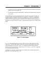
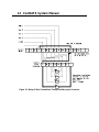
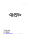
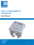
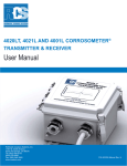
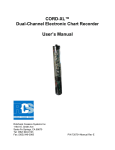
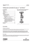
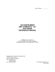
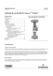
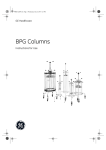
Serial Number
CorrDATSJ SYSTEM
USER MANUAL
Corrosion and Deposit Monitoring System
ROHRBACK COSASCO SYSTEMS, INC.
11841 E. Smith Avenue
Santa Fe Springs, CA 90670
Tel: (562) 949-0123
(800) 635-6898
Fax: (562) 949-3065
P/N 720000-Manual Rev. C
02/2003
8 1991 - 95 Rohrback Cosasco Systems, Inc. All rights reserved.
CORROSOMETER, CORRATER, CORROTEMP, are registered trademarks and
CorrDATS is a trademark of Rohrback Cosasco Systems, Inc.
DATS II is a trademark of Bridger Scientific Inc.
No part of this manual may be reproduced or transmitted in any form or by any means,
electronic or mechanical, including photocopying and recording, for any purpose, without the
express written permission of Rohrback Cosasco Systems, Inc.
Contents
Chapter 1 Introduction.......................................................... 1
Chapter 2 Specifications ....................................................... 5
Chapter 3 System Installation ................................................ 7
System Physical Layout ...................................................................... 7
Connection of Heated CORRATER Electrodes .......................................... 7
Connecting the Non-Heated CORRATER Probe ........................................ 8
Connecting the 9030 Plus Output to the CorrDATS Controller....................... 8
Modem Communications Setup ............................................................. 9
Using CORROSOMETER Transmitters
or Other 2 Wire Transmitters on Auxiliary Inputs.................................. 9
Chapter 4 System Operation................................................ 13
9030 Plus Settings for CorrDATS System Operation ..................................13
Deposit Monitoring Settings................................................................15
Chapter 5 Maintenance....................................................... 17
Figures and Drawings
Figure
Page
1.1
CorrDATS System ............................................................................ 1
1.2
System Configuration Options .............................................................. 2
3.1
Auxiliary Wiring for 9030 Plus............................................................. 9
3.2
Auxiliary Wiring for 2 Wire Transmitters Bypassing
Auxiliary Input Connector .............................................................11
3.3
Auxiliary Wiring for 2 Wire Transmitters Via
Auxiliary Input Connector .............................................................12
1
Chapter 1
Introduction
Figure 1.1 CorrDATS System (excludes PC)
The CorrDATS system provides a comprehensive data logging of corrosion, fouling and
deposit monitoring. The data may be transferred directly to a PC, or over a modem link, for
analysis. A particular feature of this system is the ability to monitor corrosion rate on the heat
transfer surface, where metal temperatures are higher than the bulk water temperature. The
increased temperature of the heat transfer surface can produce a significant increase in
corrosion rates which need to be monitored.
Rohrback Cosasco Systems and Bridger Scientific have collaborated to produce the new
Rohrback Cosasco Systems CorrDATS integrated corrosion and deposit monitoring system.
2
CorrDATS System Manual
In the actual field environment of water treatment, it is necessary to maintain the proper
balance between low pH (more acidic) which increases corrosion, and high pH (more alkaline)
which increases scaling tendency. Consequently, to achieve this balance, the operator must
control pH, conductivity, corrosion, scaling and deposition. The CorrDATS unit was
developed to specifically blend comprehensive, sophisticated yet field-proven technologies
into an economical package.
]
Figure 1.2 Flow Tube Arrangement
The heat exchanger flow tube of the system is matched to the alloy of the plant heat exchanger
to be monitored in the field. The flow through the tube is programmed and controlled to
represent the most critical plant condition, usually the lowest flow velocity. The heated
surfaces are programmed and controlled to represent the most critical heat transfer conditions,
normally the highest heat flux, and connected to the highest water temperature from the plant
heat exchanger outlet. This sets up the system for scale and deposit monitoring.
All of the parameters necessary to perform heat transfer analysis are monitored and recorded.
As deposits (scaling, microbial slime, sediments) accumulate, the tube surface becomes
thermally insulated and the change in Heat Transfer Resistance (HTR) is electronically
recorded. Changes in HTR due to corrosion and corrosion products may also be detected.
In many systems, the heat exchanger tubing is a copper- based alloy and the rest of the system
is carbon steel. Separate elements of the corrosion inhibition must be simultaneously regulated
to prevent corrosion of both of these alloys. In addition, the corrosion rate on the heated
exchanger tube material can change with temperature. The CorrDATS system is unique
because:
Chapter 1 Introduction 3
1. It provides CORRATER measurements from electrodes which are made from the same
material as the heat exchanger, and;
2. The electrodes are under the same heat flux conditions as the deposit monitoring section
of the system.
The new 9030 Plus corrosion monitoring electronics are used in the CorrDATS system, for
increased flexibility (see separate data sheet for more details). The 9030 Plus unit monitors
multiple parameters, including: corrosion rate and pitting tendency from two CORRATER
probes; pH from an optional pH probe; conductivity from an optional conductivity probe (an
alternative to a second CORRATER probe); or approximate conductivity from a CORRATER7
probe.
Figure 1.3 System Diagram
Any four of the measured parameters from the 9030 Plus unit are data logged by the main
control unit. The main control unit will store up to 124 records, and the cycle time of each
record may be set from 0.05 to 99+ hours. PC Software is included with the system for
uploading of the accumulated data. Data files are in ASCII format, (*.prn files) for importing
into standard spreadsheet programs.
In addition to this systems overview manual also included are the individual manuals on the
basic 9030 Plus Unit and the DATS II unit.
4
CorrDATS System Manual
5
Chapter 2
Specifications
Operational
!
Maximum Heat Flux: 50,000 Btu/hr. ft2
!
Maximum Fluid Temp: +200°Deg F
!
Maximum Fluid Pressure: 50 psi
!
Flow Velocity Range: 1-10 ft/sec
!
Reynolds No: 10,000 - 100,000
!
Tube Size: 7/8" dia.
!
Tube Alloy: Any commercially available
!
Enclosures: Plastic Sealed enclosures, Stainless steel/Aluminum heat exchanger case
!
Corrosion Rate: 0 - 1000 mpy
!
Imbalance (Pitting Index): 0 - 1000 pitting units
!
Operating Range: Conductivity (!mhos/cm) divided by corrosion rate (mpy) > 4
!
9030 Plus Data Logged Parameters: Max 4
!
9030 Plus Inputs: 2 Channel Corrosion Rate, 2 Channel Imbalance, 2 Channel
Temperature, 2 Channel approx. Conductivity (from CORRATER),
1 Channel Conductivity (with optional Conductivity probe, in place of
1 CORRATER Channel)
!
Number of Stored Readings: 124
6 CorrDATS System Manual
Mechanical
!
Equipment enclosures excluding 9030 Plus unit are unrated moisture and splash proof
resistant
!
9030 Plus unit is NEMA 4X rated
!
Data logger/Control Unit 18" (460 mm) L X 16" (410 mm) W X 9" (230 mm) D
!
Heat Exchanger 36" (1070 mm) L X 12" (300 mm) W X 9" (230mm) D
!
Flow Controller 18" (460 mm) L X 16" (410 mm) W X 9" (230 mm) D
!
9030 Plus Unit 7.5" (190 mm) L X 7' (178 mm) W X 4.5" (115 mm) D
Electrical
!
Separate systems require for 115 VAC and 240 AC
!
115 VAC System 15 Amp 50/60 Hertz (requires ground fault interrupt circuit)
!
240 VAC System 7.5 Amp 50/60 Hertz (requires ground fault interrupt circuit)
Environmental
!
Temperature rating: 32 - 100°F (0 - 38C)
!
Humidity: 0 - 90% RH
!
Usage: Protected from Weather
PC Requirements
!
IBM PC or compatible
!
MS DOS 3.3 or higher
!
2400 Baud modem for remote communications
7
Chapter 3
System Installation
System Physical Layout
The piping arrangement of the Heat Exchanger, the Flow Controller, and the separate
CORRATER probe are important, to permit correct operation and access for the cleaning of
the Heat Exchanger tube when required.
On the flow inlet to the system, the input piping to the Heat Exchanger should be made with a
union, and a Swagelok type coupling onto the Heat Exchanger tube.
WARNING! The Swagelok type coupling should be through bored for attachment to the
tube, but the ferrules MUST be NYLON or TEFLON to prevent damaging the tube.
On the outlet to the Heat Exchanger another similar Swagelok type fitting and union should be
used to connect to a Tee in which the unheated CORRATER probe is inserted (see 9030 Plus
manual fig 3.4). After this Tee fitting another union is desirable. These unions permit the
easy removal of the items adjacent to the Heat exchanger that permit easy access to clean the
tube in the Heat exchanger when required. A 7/8" nylon tube cleaning brush on a 36"
extension is ideal for cleaning the tube.
Connection of Heated CORRATER Electrodes
The heated CORRATER electrodes in the heat exchanger have a cable connection already
made at the Heat Exchanger end. This cable is the middle cable of the three coming out of the
exchanger. The free end of this cable has leads ready for connection to the probe 1 input of
the 9030 Plus unit. Keep this cable separated from the power cable to the Heat Exchanger.
The cable should pass through the cable gland on the 9030 Plus unit. Be careful that the
connections are exactly as shown in figure 3.2 of the 9030 Plus Manual and similar but rotated
180 degrees from the cable on probe 2.
A
B
C
D
E
-
Red
White
Black of Red/Black pair
Black of Black/Green pair
Black of Black/White pair
8
CorrDATS System Manual
F G -
Green
Grey (Cable Screen)
Connecting the Non-Heated CORRATER Probe
The second probe, commonly with carbon steel electrodes is connected to the 9030 Plus unit
with the second probe cable already installed on the 9030 Plus unit. Care should be taken
when installing the probe into the Tee fitting to ensure the electrodes are in the flow, but that
the probe body does not obstruct the flow.
Connecting the 9030 Plus Output to the CorrDATS
Controller
Connect the analog output of the 9030 Plus unit (fitted with the plastic connector) to the
Auxiliary Input of the CorrDATS controller and data logger. The connections of the 9030
Plus Channels 1 to 4 are pre-made to the auxiliary inputs 1 to 4 respectively of the Controller.
The wiring connections to the 9030 Plus unit are as follows:
NOTE:
Loop 1 is on the right and Loop 5 is on the left.
Loop 1+
Loop 1B
Loop 2+
Loop 2B
Loop 3+
Loop 3B
Loop 4+
Loop 4B
Loop 5+
Loop 5B
Red
Black of Red/Black pair
White
Black of White/Black pair
Blue
Black of Black/Blue pair
Green
Black of Green/Black pair
not connected
not connected
Chapter 3 Installation
Figure 3.1 Auxiliary Wiring for 9030 Plus
(Self powered 4-20 mA loops)
WARNING! Where an other transmitter, such as the model 4020LT
CORROSOMETER Transmitter, is used in place of the 9030 Plus outputs, the
corresponding outputs from the 9030 Plus unit must be disconnected (see
section on using CORROSOMETER Transmitter or other 2 wire transmitters
on auxiliary outputs).
9
10 CorrDATS System Manual
Modem Communications Setup
A relatively simple communication setup is used between the CorrDATS and the
PC, without any form of error connection protocol. The modem at the PC
needs to have its default stored profile set for no error correction. This
normally means setting the &Q register to 0 (default is typically 5 for full error
correction options). Modems do vary in their commands, and if neccessary
reference should be made to the manual, RCS can assist if required.
Setting up the modem to the default string requires a communication program
such as PROCOMM.
To setup the &Q=0 for startup, first, with a program such as PROCOMM, set
up the modem being used. Type A7 and enter; the modem should respond with
OK. Type AT&Q0. This will normally set the &Q register to 0. Type
AT&W0. This will normally set the default profile with &Q=0 for all future
startups. The DATS program should then be run normally.
Using CORROSOMETER Transmitters or Other
2 Wire Transmitters on CorrDATS unit
The auxiliary inputs on the CorrDATS controller unit may be from any 4-20mA
inputs. If CORROSOMETER transmitters or other 2 wire transmitters (such as
for pressure drop tube) are used, then the following wiring changes will need to
be made inside the controller unit. This additional wiring may already have
been done if the system was supplied that way. If for example one
CORROSOMETER transmitter is fitted, the following is the wiring diagram.
This makes use of an internal 24VDC supply to power the transmitter.
WARNING! If the transmitters are set up as AUX 1 and AUX 2 on the
CorrDATS controller, then loop 1 and loop 2 connections must be removed
from the 9030 Plus output terminal block and the connections insulated from
each other.
Chapter 3 Installation
Figure 3.2 Wiring 2 Wire Transmitters Bypassing Auxiliary Input Connector
11
12 CorrDATS System Manual
Figure 3.3 Wiring 2 Wire Transmitters Through Auxiliary Input Connector
13
Chapter 4
System Operation
9030 Plus Settings for CorrDATS System Operation
The settings on the 9030 Plus unit for Probe 1, which is the heated electrode set are slightly
different from a standard CORRATER probe because the electrode area is three times larger
than the standard CORRATER electrodes. Standard electrodes are 5 cm 2 each, whereas the
heated electrodes on a standard f@ diameter heat exchanger flow tube are 15 cm2 each. To
compensate for this the probe alloy multiplier in table 5-1 of the 9030 Plus Manual should be
divided by three, for example: 90/10 Copper/Nickel would normally use a multiplier of 1.8 on
standard CORRATER electrodes, such as on the unheated probe, but would be set at 0.6 for
the heated electrodes.
The probe type for the heated electrodes(probe 1) should be set to A2 Electrode@.
The Probe setting for the unheated probe (probe 2) should be set to A2 Electrode@ unless a
CORROTEMP CORRATER probe has been ordered. This latter probe includes a 100 ohm
RTD temperature sensor.
The Multiplier to be used for the heated electrodes in the flow tube are listed below according
to the flow tube size. The standard size is f@ diameter but other sized are used from time to
time according to material availability. The multiplier is computed as an inverse factor of the
surface area of the electrode surface.
Alloy multiplier to be used is:
= M x Ao
A1
Where
M = the standard CORRATER probe Multiplier
A0 = the area of the standard CORRATER probe electrode = 5 cm2
A1 = the internal surface area of the heated electrode in cm 2 (15 cm2 on
f@ tube)
For the standard f@ diameter heated flow tube:
Alloy multiplier to use =
M0x
5 cm 2
= M0
2
15 cm
3
14 CorrDATS System Manual
WARNING! Make sure that the multiplier for the heated tube is not used for the standard
unheated CORRATER probe. This factor directly scales the indicated corrosion rate.
The following is a list of multipliers for commonly used heat exchanger alloys and tube sizes.
For any other sizes the values may be calculated as shown above using the internal surface area
of the tube electrodes (the length of each tube electrode = 1.00").
UNS Code
Material
Standard CORRATER
Probe Multiplier
f@ x 0.065" Tube
Multiplier (x 0.33)
1” x 0.083” Tube
Multiplier (x 0.295)
K03005
Pipe Grade Carbon Steel
1.00
0.33
0.30
A91100
Aluminum 1100-0
0.94
0.31
0.28
A92024
Aluminum 2024
0.88
0.29
0.26
C11000
Copper 110 ETP Comm. Pure
2.00
0.67
0.59
C44300
CAD 443 Arsenical Admiralty
1.67
0.56
0.49
C44500
CDA 445 Phosphorized Adm.
1.68
0.56
0.50
C64200
CDA 642 A1 Silicon Bronze
1.48
0.49
0.44
C68700
CDA 687 Alum. Brass Arsenical
1.62
0.54
0.48
C70610
CDA 706 90/10 Copper/Nickel
1.80
0.60
0.53
C71500
CDA 715 70/30 Copper/Nickel
1.50
0.50
0.44
G41300
AISI 4130 Alloy Steel
1.00
0.33
0.30
N04400
Monel 400 Nickel
1.13
0.38
0.33
N05500
Monel K-500 Nickel
1.04
0.35
0.30
N06022
Hastelloy C22
0.85
0.28
0.25
N06600
Inconel 600 Nickel
0.95
0.32
0.28
N08020
Carpenter 20 CB3 SST
0.98
0.33
0.29
N08800
Incolloy 800
0.89
0.30
0.26
N08825
Incolloy 825
0.88
0.29
0.26
N10276
Hastelloy C276
0.86
0.29
0.25
R50400
ASTM B-348 Grades 2-4 Titanium
0.75
0.25
0.22
S30400
AISI 304 Stainless Steel
0.89
0.30
0.26
S31600
AISI 316 Stainless Steel
0.90
0.30
0.27
S31603
AISI 316L Stainless Steel
0.90
0.30
0.27
S31803
Duplex Stainless 2505
0.89
0.30
0.27
S32750
Duplex Stainless 2507
0.88
0.30
0.26
Chapter 4 System Operation
15
Deposit Monitoring Settings
In general, for a plant application, the CorrDATS deposit monitoring section of the system is
programmed to represent a section of the heat exchanger, where the worst conditions are
represented. Alternatively the system may be programmed for some separate test and
evaluation purposes. Calculation and setting of the required heat flux and flow rate is given is
the DATS II manual.
Some general principles can give guidance in these settings, to make the measurements
representative.
1. The design or calculated heat flux for the plant exchanger to be evaluated should be
used for the heat flux setting.
2
If sealing (calcium and magnesium salts) and corrosion are the primary concern the
CorrDATS heat exchanger tube should be positioned on the hot outlet of the actual
exchanger to operate on the hottest water flow temperature and the greatest
residence time.
3. If fouling is the primary problem the CorrDATS heat exchanger tube should be
positioned at the inlet to the plant heat exchanger since lower temperatures generally
promote bio fouling but high temperature discourages it.
4. Scaling deposits and poor corrosion protection due to poor inhibitor filming will
generally occur at the lowest velocity points in the heat exchanger. This may often
occur on a system of heat exchangers at the one with the longest pipe runs, or
farthest away from the cooling tower.
16 CorrDATS System Manual
17
Chapter 5
Maintenance
Details of instrument calibration and maintenance are given in the 9030 Plus and DATS II
manuals. System maintenance is most likely to comprise of cleaning of the heat exchanger
flow tube and possibly the flow meter as well as any external filters installed as recommended.
Apart from physical debris which should generally be trapped by the filters, the flow meter and
heat exchanger tube should not become blocked more than the heat exchanger they are set to
represent.
NOTE: If the tests are for separate evaluation rather than system
simulation, this may not be the case.
Initial installation in Chapter 3 recommends assembly with unions to allow
relatively simply access to clean the heat exchanger tube and flow meter.
Significant scale can be removed with an acidized solution, and nylon tube
cleaning brushes and extension handles are available from number of sources
(such as McMaster Carr in the USA).
Due to the relatively complex heater tube assembly, it is not normally
recommended for the user to disassemble this part. This is because of the
careful loading of the assembly required to maintain the seals between the
electrodes, and to avoid any leakage into the heater area with its 115 VAC or
240 VAC supplies. A complete spare assembly should be considered so that the
alternate assembly may be returned for repair and replacement if necessary.