1
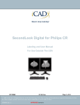
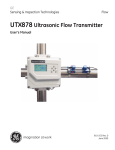
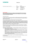
Mammography Applications
for MAMMOMAT 1000/3000 Nova
Introduction
This booklet is intended as an application handbook
for use with Siemens MAMMOMAT® 1000 and 3000
Nova.
The booklet contains advice on positioning, instructions for choice of exposure and proper positioning
of the Automatic Exposure Control (AEC) detector.
There are also instructions on the use of Opcomp®
and Opdose®.
This handbook with helpful hints and directions is
a complement to the operator’s manual. It should
be noted that this is not a textbook and that we
make no claim of complete coverage of the subjects
discussed. The responsibility for medical judgements and directions remains with the attending
physician.
For information on other questions relating to the
operation of your MAMMOMAT 1000/3000 Nova,
please refer to the Operating Instructions.
2
Contents
General advice
Positioning
Compression
AEC-detector
Choice of exposure
Opdose
5
6
6
8
9
10
Image quality
Radiation quality
Film/screen combinations
Processing
13
14
15
16
Positioning
Mediolateral oblique view, MLO
Cranio-caudal projection, CC
Lateral projection
Medio lateral, ML
Latero medial, LM
17
17
20
22
23
24
Specialized mammographic technique
Spot compression
Magnification
25
25
26
Biopsy methods
Biopsy hole plate
Shadow cross
Stereo
27
27
27
28
3
General advice
It is always important to inform the patient how
the examination will be performed. It should be
explained why it is necessary to compress the breast
and that it will be uncomfortable for a short time.
Always keep the patient under observation. If the
patient is very sensitive to pain or very nervous, it is
recommended that two radiographers attend in
the room. Begin each setting by chosing the correct
slide marker for the desired projection. With Siemens
fixed markings, the risk of faulty marking is limited.
The marking for a cranio-caudal projection is always
found on the lateral side of the breast.
5
GENERAL ADVICE
Positioning
Correct positioning of the breast is extremely important. If the
entire breast is not in the X-ray field, or there is something blocking the X-ray field, the whole diagnosis can be incorrect. It is also
easier to apply good compression when the positioning is correct.
Compression
Proper and adequate compression is necessary in order to reduce
the radiation dose, displace the tissue apart and avoid blurring
due to motion. Inadequate compression can, for example, mean
that small micro-calcifications do not appear on the X-ray image,
as a result of which the patient risks getting an incorrect diagnosis.
Opcomp
Siemens MAMMOMAT 1000/3000 Nova are fitted with Opcomp.
Opcomp senses for each individual breast when the compression
force is sufficient for optimal image quality. The force can be
increased but this only adds to the discomfort and does not provide
any improvement in image quality. Opcomp is purely an aid. It
is always the operator who decides if the compression is to stop
before, after or on the Opcomp value.
When using Opcomp, the foot switch is to be kept pressed down
during the whole compression process. Using a pumping technique on the foot switch can result in the Opcomp indication failing
to appear.
6
1 Set the maximum value for the
compression force – 20 kg – unless
your facility has other guidelines.
Select automatic decompression
(however, not when biopsies and
localizations are to be performed).
Apply compression until the breast
is evenly and firmly compressed.
Ensure that no folds form in the skin.
2 When using Opcomp:
Begin by applying
compression until the
compression plate comes
into contact with the
skin (3-5 kg). Smooth out
any folds in the skin.
Press the foot switch all the way down, continue compression
until the plate stops and the green OC lamp on the stand display is
lit. Keep the patient under observation.
Studies have shown that the Opcomp value on average is 9-12 kg
for the CC view and 13-16 kg for the MLO view. However, some
breasts may require up to 20 kg. This is not harmful. The breasts
withstand this temporary deformation, but pay attention to the
patient. Do not override the patients pain-treshold.
More information on Opcomp can be found in the operating
instructions.
7
GENERAL ADVICE
AEC-detector
In order to obtain the correct density on the images, the AEC
detector should be moved to the densest area in the breast. Move
the AEC-detector lever to the marking, which corresponds with
the marking in the compression plate. Ensure that the breast completely covers the position of the AEC detector with a 2 cm margin,
otherwise the chamber will be measuring air. Do not forget to
return the detector to the chestwall-close position after each patient.
The image on the left demonstrates the
cassettes turbo release function. The text
does not mention this aspect of the unit.
Should this image be removed or should
text be added.
8
GENERAL ADVICE
Choice of exposure
Both Siemens MAMMOMAT 1000 and
Siemens MAMMOMAT 3000 Nova are
equipped with automatic exposure control
(AEC).
Only the kV value is set manually. After
exposure, the mAs value obtained can
be read on the generator control panel.
If desired, both kV and mAs can also be
chosen manually. When the mAs button is
first activated, a value of 100 mAs is shown
on the display. Continue to press the mAs
button until the desired value is shown,
then make the exposure.
9
GENERAL ADVICE
Opdose
Siemens MAMMOMAT 1000 and 3000 Nova are equipped with an
automatic exposure system - Opdose. Opdose suggests the exposure
parameters depending on the thickness of the breast. Both kV
and an anode/ filter combination are suggested in accordance with
what has been preset for the respective thickness interval (see
program table on page 12). That is, the larger the breast the more
the high-energy radiation, which enables the dose and exposure
time to be kept down. The user must confirm the values before an
exposure is made.
1 Make sure that the
“Auto” button is pressed in.
Position the patient and
apply the compression.
The compression force must
be at least 6 kg for the Opdose
to activate.
10
GENERAL ADVICE
2 On the control panel, an
indicator lamp will now be flashing over the program which is
suggested. Confirm by pressing
the program button for the
suggested program. Make the
exposure.
It is recommended that the
same program is kept for the
entire examination. If you get
a flashing light suggesting a
different program, it is not necessary to accept this suggestion.
Just make the exposure. The program used for the last exposure
is maintained.
As soon as you press a button which is not blinking you leave
the auto-mode for Opdose. Always remember to check that the
auto button is pressed in when you start with the next patient.
The four programs can be set to suit the customer’s requirements
on installation.
Please refer to the Operating
Instructions when changing
program settings.
You can also choose to make the
exposure using a program which is
set manually. On the MAMMOMAT
1000/3000 Nova, you then choose
the kV value, the anode/filter
combination and the film/screen
combination (H/D button).
11
GENERAL ADVICE
The program values as preset from the factory are,
for Mo/W tube:
Program
Compression
thickness
kV-value
Anode/Filtercombination
1
0 - 29 mm
26
Mo / Mo
2
30 - 44 mm
27
Mo / Mo
3
45 - 59 mm
27
Mo / Rh
4
≈ 60 mm
26
W / Rh
Program
Compression
thickness
kV-value
Anode/Filtercombination
1
0 - 29 mm
26
Mo / Mo
2
30 - 44 mm
27
Mo / Mo
3
45 - 59 mm
27
Mo / Rh
4
≈ 60 mm
28
Mo / Rh
for Mo tube:
The program settings in the table are only suggestions. Each facility
may choose the most suitable setting for the film/screen in use.
The thickness intervals can only be changed by a service engineer.
12
IMAGE QUALITY
Image quality
Several factors affect the image quality. In addition to the previously mentioned factors such as positioning, compression and
the position of the detector, the cooperation between the doctor,
radiographer and patient is of greatest importance.
13
IMAGE QUALITY
Radiation quality
The radiation quality is determined by the kV value, anode material
and filter.
Low kV means that the image contrast increases. The kV value to
be used is determined by each individual facility. Some film/screen
combinations are recommended to be used with a high kV (28-30)
in order to keep the contrast down.
At 25 kV and large focal spot, the tube current for a Siemens
mammography-X-ray tube with a molybdenum anode is 150 mA.
This is an important factor, since high mA gives a short exposure
time and, consequently, a reduced risk of motion artifacts.
The Siemens MAMMOMAT 3000 Nova can be configured with
an X-ray tube with two different anode materials - molybdenum
and tungsten, plus various filter combinations of molybdenum
and rhodium. At 25 kV, the tube current with tungsten (W) anode
is 188 mA. This, in combination with a rhodium filter, will provide
high energy radiation and also reduce dose to the patient.
See the section on Opdose for instructions on use of the system.
The focus size need not be selected. Fine focus will automatically
be selected when the magnification table is inserted.
14
IMAGE QUALITY
Film/screen combinations
Mammography film and screens are made to provide high resolution and high contrast. For normal mammography, screens with
the highest possible resolution should be used. Faster screens
can be used for magnification, to reduce the exposure time. The
resolution will be maintained through the small focal spot.
Cassettes and screens should be cleaned regularly, and you
should check your cassettes to ensure that the contact between
film and screen is the best possible.
It is important to keep all surfaces in the dark room clean
(wet wiping) to avoid dust in the cassettes.
15
IMAGE QUALITY
Processing
Even a picture which has been properly exposed and skillfully
executed can easily lose in quality in a poor development process.
The film processing machine is the heart of the mammography
department. Deterioration in image quality can often be traced to
a disorder in the development process.
Modern film processing machines can be programmed for various
processing times, which means that the processing time can be
adapted to mammography film.
The development temperature should be approximately 35°C (95°F).
Chemicals suitable for mammography film should be chosen
and be mixed in small tanks, so that they always are “fresh”.
Replenishment should be adapted to mammography film.
The film processing machine should be inspected daily. The
temperature, film speed, film contrast and film base fog should be
controlled. For this purpose, a sensitometer and a densitometer
are required.
16
Positioning
Mediolateral oblique
view MLO
For routine examinations, the MLO projection is to be preferred over the 90° lateral
projection. More of the breast tissue can
be seen in the upper outer quadrant and
the axilla. Furthermore, it is easier to carry
out the application with this setting.
MLO
CC
Criteria:
The pectoral muscle should be depicted obliquely from above and
be visible down to the level of the nipple or further down. The
shape of the muscle should be depicted weakly convex as a sign
that the muscle is completely relaxed and medially prominent.
The compression should be proper over the whole image area.
The nipple should be depicted in profile and a small stomach fold
should be visible as a sign that the whole breast is reproduced.
17
POSITIONING
1 Set the angle for the desired projection (30°- 60°). It is best to
adapt the angle to each patient. The object table should be parallel
with the pectoral muscle. Many clinics want to use the same projection angle for all patients, in order to be able to reproduce the
image on the next occasion.
2 Be sure to adjust
the height so that the
top edge of the object
table is on a level with
the axillary fold.
18
POSITIONING
3 Place the patient’s hand on the lower
part of the handle.
Turn the patient 45° or more in towards
the stand. Ask the patient to stand steadily and not to move her feet.
Instruct the patient to lift her elbow but
still keep her hand in the same position.
Ask the patient to bend slightly forward,
then take hold of the lifted arm and the
breast from below.
At the same time as you move the
patient in towards the object table, draw
the breast parenchyma medially.
Ensure that the patient relaxes and ask her to lower her shoulders
and at the same time roll them forward.
Draw the breast forward at the same time as you apply compression and hold on the clavicle with your other hand so that the
compression plate is just clearing the clavicle. When the compression
is sufficient, using Opcomp or your own selection, make sure that
nothing blocks the field of the intended image.
4 Make sure the patient is
at ease and ask her to stand
absolutely still, before you leave
her to make the exposure.
19
POSITIONING
Cranio-caudal projection
CC
MLO
CC
Criteria:
The whole breast parenchyma should be depicted. The fatty tissue
closest to the breast muscle should appear as a dark stripe on the
X-ray and behind that it should be possible to discern the pectoral
muscle. The nipple should be depicted in profile.
1 Lift the breast approximately
2 cm and adjust the height so
that the object table touches your
hand.
20
POSITIONING
2 Stand on the medial side of
the breast which is to be X-rayed
(or behind the patient). Ask the
patient to turn her head in your
direction (good to have eye contact). Take hold of the patient’s
back and shoulder in order to
press her closer to the table.
Then with your other hand, take
hold under the breast and lay it
on the table. Draw the breast
somewhat towards you so that
the lateral side is turned forwards.
Grasp the breast with a grip from
the sides so that you can guide it
better. Bear in mind that you
should not draw the lateral side
forward so much that the medial
side is lost.
3 Apply compression while keep-
ing an eye open for folds on the
lateral side. Use your hand on the
patients shoulder to stretch the
skin. Ensure that nothing blocks
the X-ray field.
4 Make sure the patient is at ease
and ask her to stand absolutely still,
before you leave her to make the
exposure.
21
POSITIONING
Lateral projection
The lateral projection can be taken either from the medial side
(mediolateral, ML) or from the lateral side (lateromedial, LM). If no
oblique projection is taken, the mediolateral projection may be
preferable since the lateral side of the breast, where pathological
changes are most commonly found, is then closest to the film.
However, if you want to include as much as possible of the medial
side, then the LM projection should be chosen.
Criteria:
The pectoral muscle should be
depicted as a narrow light band on
at least half of the picture. The nipple
should be depicted in profile and a
clear stomach fold should be visible
under the breast.
22
90°
ML
mediolateral
POSITIONING
Medio lateral
ML
1 Set the X-ray tube in a 90° lateral
projection. Ensure that the correct slide
marker is used.
2 Set the height to the axillary fold.
3 Ask the patient to put up her arm along
the object table and stretch it well forward.
4 Grasp the breast from below and draw
it out while applying compression. Place
your other hand on the patient’s back and
press her in towards the stand.
5 If the other breast blocks the field of
the view, ask the patient to keep it out of
the way. You may wish to help her with
this to avoid unnecessary turning. Pull the
patient’s hand carefully to the side so that
only her fingertips are holding the breast.
A wide paper plaster can also be used –
tape from the sternum and fix it, after drawing the breast back, onto the patient's back.
6 Make sure the patient is at ease and
ask her to stand absolutely still, before you
leave her to make the exposure.
23
POSITIONING
Latero medial
LM
90°
LM
lateromedial
1 Set the tube in a 90° lateral projection.
Ensure that the correct slide marker is used.
2 Set the height to the uppermost point
of the sternum. Position the patient with the
object table between her breasts.
3 Ask the patient to lift her arm and place
her hand on the handle while keeping the
elbow lifted. Then ask the patient to place the
point of her chin as far forward as possible
on the edge of the object table.
4 Grasp her breast from below and draw it
outwards. At the same time as you apply the
compression, the patient must be pressed in
towards the table. Take care to ensure that
her arm is not squeezed.
5 Ensure that nothing blocks the X-ray
field. Make sure the patient is at ease and
ask her to stand absolutely still, before you
leave her to make the exposure.
24
SPECIALIZED MAMMOGRAPHIC TECHNIQUES
Specialized mammographic technique
Spot compression
Spot compression images are valuable when improved compression
is desired over a small area and overlapping structures need to be
separated. Since scattered radiation is reduced with this technique,
it is possible to obtain high contrast and detailed images.
1 Set the tube at the angle desired. Choose the correct marker.
Mount the spot plate and corresponding aperture. Sometimes the
spot view can be obtained without an external aperture, or with
a larger aperture (axilla) if you want to visualize the surrounding
area.
2 Measure accurately (use a ruler) on the X-ray image where the
lesion is to be found. Measure from the nipple straight in and then
at right angles to the area of interest. Transfer the measurement
to the breast and make a small crossmark.
3 Inform the patient that it may feel more unpleasant with the
spot plate. Compress thoroughly and ensure that the cross lands
right under the plate. Make sure that no folds in the skin are formed.
4 Tell the patient to stand absolutely still and leave her to make
the exposure.
Note: Opcomp shall be neglected when spot-compression plates
are used.
25
SPECIALIZED MAMMOGRAPHIC TECHNIQUES
Magnification
When making exposures with a magnification table, the same
positioning methods are used as for normal images or spot
compression images.
There are two different compression plates available, a flat
plate used without a aperture and a spot compression plate with
a corresponding aperture.
Take care to compress thoroughly. Ask the patient to hold her
breath. It is useful to practice this procedure in advance. “Breath
in, breath out and hold your breath”.
Since we use a smaller focal
spot in magnification mode,
the exposure times are longer
and therefore it is of utmost
importance that the compression is as firm as possible
and that the patient holds her
breath.
Note: Opcomp shall be
neglected when magnification tables are used.
BIOPSY METHODS
Biopsy and localization methods
Mammography is a superior method for early detection of breast
cancer. Many pathological changes that are discovered are so
small that it is not possible to carry out palpation guided biopsies.
X-ray guided biopsies can be carried out in various ways and with
different means.
Biopsy hole plate
A hole plate (perforated compression plate) with a coordinate
system helps the physician when making hand controlled biopsies.
Make an exposure in a CC projection using a biopsy hole plate.
Evaluate and use the coordinates to calculate where the needle
should be inserted. To check the depth of the needle, make a right
angle exposure (compress carefully) with the needle remaining in
the breast. Evaluate and make necessary adjustments. Carry out
the biopsy procedure.
Remember to switch off the automatic decompression.
Shadow cross
A shadow cross attachment with a coordinate system helps the
physician when making hand controlled biopsies. A detailed step
by step information on how to use the shadow cross is found
in the separate Operating Instructions “Biopsy attachment with
shadow cross”.
27
BIOPSY METHODS
Stereo
On the Siemens MAMMOMAT 3000 Nova, there is the possibility
of connecting up a stereo biopsy attachment. With the aid of
this stereo attachment, biopsies can be performed both with fine
needle and core-gun technique. Instructions on how the attachment is mounted and used is described in the separate Operating
Instructions “Stereotactic Biopsy Attachment”. The following are
some advices on how the examination can be made easier for the
patient.
1 Inform the patient about the procedure. Explain that the
examination can take time (at least 20 minutes) and that she must
sit still subject to compression the whole time. Explain that the
greatest source of unpleasantness is not the actual needle-puncture
but rather the sitting position. This procedure can also be carried
out with the patient recumbent.
Show the patient the angular movement and how the cassette
is moved.
2 Ask the patient to sit in the examination chair. The chair must
be height-adjustable and be provided with lockable wheels and
adjustable arm supports. Start from as high a level as possible of
the chair (facilitates the working position). A foot ring on the
chair, or a footstool, improves the sitting position. Ask the patient
to check that she is sitting comfortably.
28
BIOPSY METHODS
3 Position and compress. Note the compression thickness so
that you can make an adjustment if the compression value
changes. Mark on the breast with a felt-tip pen the inner corners
of the compression plate. In this way, you have control over the
positioning and you will notice at once if the patient has moved.
4 Perform stereo exposures and evaluate in accordance with the
Operating Instructions for “Stereotactic Biopsy Attachment”.
5 Never leave the patient on her own. Keep eye contact and
stand close, a warm hand on her shoulder can be supportive.
Explain the procedure as it progresses.
29
On account of certain regional limitations of
sales rights and service availability, we cannot
guarantee that all products included in this
brochure are available through the Siemens
sales organization worldwide. Availability and
packaging may vary by country and is subject to
change without prior notice. Some/All of the
features and products described herein may not
be available in the United States.
The information in this document contains
general technical descriptions of specifications
and options as well as standard and optional
features which do not always have to be present
in individual cases.
Siemens reserves the right to modify the design,
packaging, specifications and options described
herein without prior notice. Please contact your
local Siemens sales representative for the most
current information.
Note: Any technical data contained in this
document may vary within defined tolerances.
Original images always lose a certain amount
of detail when reproduced.
For accessories please refer to:
www.siemens.com/medical-accessories
Headquarters
Siemens AG, Medical Solutions
Henkestr.127, D-91052 Erlangen
Germany
Telephone: +49 9131 84-0
www.siemens.com/medical
Contact address
Siemens AG, Medical Solutions
Special Systems
Allee am Röthelheimpark 2
D-91052 Erlangen
Telephone: +49 9131 84-0
© 2004, Siemens AG
Order no. A91100-M1600-C924-1-7600
Printed in Germany
GP 65924 WS 07042.5