1
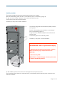
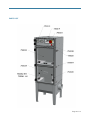
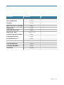
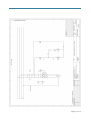
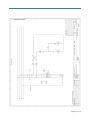
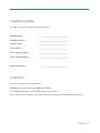
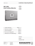
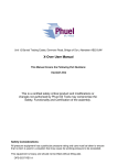
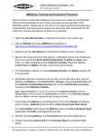
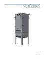
Page 1
! of 14
!
Installation and Operation - OMF1000
Issue Date: 26 September 2014
Page 2
! of 14
!
CONTENTS
Contents
3
Note
4
DIRECTIONS FOR USE
4
PRIOR TO USE
5
PREPARATION
5
INSTALLATION
5
ELECTRICAL CONNECTIONS
5
COMMISSIONING
5
OPERATION
6
PRINCIPLE OF OPERATION
6
CONTROLS
6
FILTER REPLACEMENT
6
FILTER ACCESS
7
PARTS LIST
8
FAULT FINDING
10
COMMISSIONING
13
SUPPORT
13
DECLARATION OF CONFORMITY
14
Page 3
! of 14
!
NOTE
Directions for Use
The OMF1000 is built to CE standards (1995) and conforms to HSG258 (controlling airborne contaminants at
work). As such, it must be operated in strict accordance with this manual.
The OMF1000 is designed for indoor installation only and must be protected from excessive moisture. Always
make sure that good access is provided for the maintenance of the OMF1000.
WARNING! Risk of personal injury, fire or explosion.
•
The OMF1000 must not be used in an environment where there is a risk of explosion from dust or gases in
explosive concentrations
•
The OMF1000 must not be used for extracting toxic substances
•
The OMF1000 must not be used without filters
•
Always isolate the mains power before changing filters or removing any components from the OMF1000
Page 4
! of 14
!
PRIOR TO USE
PREPARATION
Immediately upon receiving the OMF1000, examine the packaging for any damage that may have occurred
during shipment. In the event of any damage please contact the supplier immediately.
INSTALLATION
Please refer to the model information label on the OMF1000 to check its weight. The unit must be installed on
a suitable level floor that is able to support its weight. Before installation, check that adequate space is
available for replacement of filters.
ELECTRICAL CONNECTIONS
The unit is pre-wired and fully tested for operator safety. Unscrew 2 retaining screws at the right hand side of
the control panel and open. The electrical connections will be found on the electrical panel. The cable entry is
located on the left hand side.
Take care not to pinch the flexible tubes, or electrical cables.
Switch on unit to check the electrical installation/ fan rotation. Incorrect fan rotation will result in poor
performance.
COMMISSIONING
The unit should undergo commissioning testing by the installer. A commissioning certificate is provided at the
rear of this manual.
Page 5
! of 14
!
OPERATION
PRINCIPLE OF OPERATION
The OMF1000 is supplied with:
•
Pre Filter
•
HEPA filter H10
•
Centrifugal fan assembly
Air is drawn through the two filters in an upward direction, and the clean air expelled at the rear. The
condensate will collect in the base where it is discharged through the drain provided.
CONTROLS
All electrical equipment and controls are located in the electrical enclosure.
1) MAINS ISOLATOR
Power on/off
2) FILTER GAUGES
Indicates filter condition with ‘filter full’ indicator
3) RED LIGHT Advises motor overload
4) WHITE LIGHT
Power on
FILTER REPLACEMENT
When filter 1 is full it can be cleaned. For the best results apply a degreaser to the dirty face and allow to
absorb. Rinse, applying the process to the top of the filter to allow the dirt to be washed out downwards.
Allow to drain until dry.
Page 6
! of 14
!
FILTER ACCESS
The pressure gauge will indicate the initial (clean) pressure of the system.
Note this initial reading when the filter is commissioned. (see ‘commissioning’ page 10)
To gain access to the filter, release the door latches and open the door.
Lower levers (A) into the horizontal position.
The filters (1) and (2) can now be withdrawn.
The pressure gauge will indicate the initial (clean) pressure
of the system.
Note this initial reading when the filter is commissioned.
(see ‘commissioning’ page 12)
To gain access to the filter, release the door latches and
open the door.
Lower levers (A) into the horizontal position.
The filters (1) and (2) can now be withdrawn.
WARNING! Risk of personal injury.
• Always isolate the mains power before changing
filters or removing any components from the
OMF1000.
• Use necessary PPE
NOTE: Filter 1 weighs 15kg dry. However, when wet
it will be considerably heavier.
To refit the filters, place in the runners with seal uppermost and push fully home.
Then raise both levers (A) into the vertical position, and the filter(s) will be locked into place. Close the door.
Parts list schematic
Page 7
! of 14
!
PARTS LIST
Page 8
! of 14
!
Description
Part Number
Qty
Filter 1 ( Pre Filter )
750029
1
Filter 2 (HEPA Filter)
750033
1
Fan RH28
301023
1
Motor Overload 1.6 - 2.4A 230V
750004
1
Hinge Lift-off
750050
5
Over Centre Door Latch
750054
3
750020 -1700
2
Pressure Gauge 63mm 1000Pa
750131
2
Clamp Mechanism RH
750060
2
Clamp Mechanism LH
750061
2
T Switch
750251
1
Lamp Assembly-Red
750228
1
Lamp Assembly-White
750231
1
Transformer
750135
1
Push on seal - Door
Page 9
! of 14
!
Fault finding
Fault
Remedy
Lack of Suction
Dirty filters (see page 4)
Motor does not operate
Motor tripped - reset trip in elec panel
Faulty motor (motor needs replacement)
Fan discharge air is contaminated
The filtration system is being by-passed. Check for
damage or incorrectly fitted filter(s), and replace as
appropriate.
WARNING! Risk of personal injury.
• Always isolate the mains power before changing filters or removing any components from the
OMF1000.
• Use necessary PPE
NOTE: Filter 1 weighs 15kg dry. However, when wet it will be considerably heavier.
Page 10
! of 14
!
"
Page 11
! of 14
!
"
Page 12
! of 14
!
COMMISSIONING
Complete the following information following installation:
Serial Number: _____________________________
Installlation Date: _____________________________
Installer Name: _____________________________
Duct Velocity: _____________________________
Filter 1 gauge reading: _____________________________
Filter 2 gauge reading: _____________________________
Signed (Engineer): _____________________________
SUPPORT
Contact your supplier, or the manufacturer:
MISTCONTROL (A Trading Name of AIRBENCH LIMITED),
14 GRANGE FARM ROAD, COLCHESTER, ESSEX, CO2 8JW, UK
Tel: 01206 791191 Fax: 01206 791091 Web: www.mistcontroluk.com Email: [email protected]
Page 13
! of 14
!
Business Name:
AirBench Ltd t/a MistControl
14 Grange Farm Road,
Colchester,
Essex.
CO2 8JW
Responsible Person:
Simon Cook
Description:
Mist Filter Unit known as “OMF1000”
DECLARATION OF CONFORMITY
BY
MISTCONTROL (A Trading Name of AIRBENCH LIMITED)
Relevant Directives
EMC Directive 2004/108/EC (when connected to standard mains sinusoidal supply).
Low voltage Directive 2006/95/EC
- EN-60204–1:2006 (Safety of machinery, electrical equipment of machines, general
requirements).
- EN-60335-2-80 (Safety requirements for electric fans and regulators).
We; AIRBENCH Limited, declare that “OMF1000” when supplied as self contained
equipment complies with the directives detailed above and therefore comply with
requirements of the Low Voltage Directive.
Signature
!
Simon Cook
Page 14
! of 14
!