1
Galil Motion Control
Firmware Command Reference
DMC40x0
11/11/2011 10:43:45
Overview
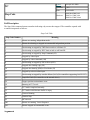
#@ABCDEFGHIJKLMNOPQRSTUVWXYZ
●
●
●
●
●
●
●
●
●
●
●
●
●
●
●
●
●
●
●
●
●
●
●
●
●
●
●
●
●
●
●
●
●
●
- - Subtraction Operator
# - Label (subroutine)
#AMPERR - Amplifier error automatic subroutine
#AUTO - Subroutine to run automatically upon power up
#AUTOERR - EEPROM checksum error and Serial Encoder timeout error Automatic Subroutine
#CMDERR - Command error automatic subroutine
#COMINT - Communication interrupt automatic subroutine
#ININT - Input interrupt automatic subroutine
#LIMSWI - Limit switch automatic subroutine
#MCTIME - MC command timeout automatic subroutine
#POSERR - Position error automatic subroutine
#SERERR - Serial Encoder Error Automatic Subroutine
#TCPERR - Ethernet communication error automatic subroutine
$ - Hexadecimal
% - Modulo Operator
& - Bitwise AND Operator
& - JS subroutine pass variable by reference
( , ) - Parentheses (order of operations)
* - Multiplication Operator
/ - Division Operator
; - Semicolon (Command Delimiter)
@ABS - Absolute value
@ACOS - Inverse cosine
@AN - Analog Input Query
@ASIN - Inverse sine
@ATAN - Inverse tangent
@COM - Bitwise complement
@COS - Cosine
@FRAC - Fractional part
@IN - Read digital input
@INT - Integer part
@OUT - Read digital output
@RND - Round
@SIN - Sine
●
●
●
●
●
●
●
●
●
●
●
●
●
●
●
●
●
●
●
●
●
●
●
●
●
●
●
●
●
●
●
●
●
●
●
●
●
●
●
●
●
●
●
●
●
●
@SQR - Square Root
@TAN - Tangent
[,] - Square Brackets (Array Index Operator)
^a,^b,^c,^d,^e,^f,^g,^h - JS subroutine stack variable
^L^K - Lock program
^R^S - Master Reset
^R^V - Revision Information
_GP - Gearing Phase Differential Operand
_LF - Forward Limit Switch Operand
_LR - Reverse Limit Switch Operand
| - Bitwise OR Operator
~ - Variable Axis Designator
+ - Addition Operator
<,>, =,<=,>=,<> - Comparison Operators
= - Equals (Assignment Operator)
AB - Abort
AC - Acceleration
AD - After Distance
AF - Analog Feedback Select
AG - Amplifier Gain
AI - After Input
AL - Arm Latch
AM - After Move
AO - Analog Output
AP - After Absolute Position
AQ - Analog Input Configuration
AR - After Relative Distance
AS - At Speed
AT - At Time
AU - Set amplifier current loop
AV - After Vector Distance
AW - Amplifier Bandwidth
BA - Brushless Axis
BB - Brushless Phase Begins
BC - Brushless Calibration
BD - Brushless Degrees
BG - Begin
BI - Brushless Inputs
BK - Breakpoint
BL - Reverse Software Limit
BM - Brushless Modulo
BN - Burn
BO - Brushless Offset
BP - Burn Program
BQ - Brushless Offset dual DAC
BR - Brush Axis
●
●
●
●
●
●
●
●
●
●
●
●
●
●
●
●
●
●
●
●
●
●
●
●
●
●
●
●
●
●
●
●
●
●
●
●
●
●
●
●
●
●
●
●
●
●
BS - Brushless Setup
BT - Begin PVT Motion
BV - Burn Variables and Array
BW - Brake Wait
BX - Sine Amp Initialization
BZ - Brushless Zero
CA - Coordinate Axes
CB - Clear Bit
CC - Configure Communications Port 2
CD - Contour Data
CE - Configure Encoder
CF - Configure Unsolicited Messages Handle
CI - Configure Communication Interrupt
CM - Contour Mode
CN - Configure
CO - Configure Extended I O
CR - Circle
CS - Clear Sequence
CW - Copyright information Data Adjustment bit on off
DA - Deallocate the Variables & Arrays
DC - Deceleration
DE - Dual (Auxiliary) Encoder Position
DF - Dual Feedback (DV feedback swap)
DH - DHCP Server Enable
DL - Download
DM - Dimension
DP - Define Position
DR - Configures I O Data Record Update Rate
DT - Delta Time
DV - Dual Velocity (Dual Loop)
EA - Choose ECAM master
EB - Enable ECAM
EC - ECAM Counter
ED - Edit
EG - ECAM go (engage)
EI - Event Interrupts
ELSE - Else function for use with IF conditional statement
EM - Cam cycles (modulus)
EN - End
ENDIF - End of IF conditional statement
EO - Echo
EP - Cam table master interval and phase shift
EQ - ECAM quit (disengage)
ER - Error Limit
ES - Ellipse Scale
ET - Electronic cam table
●
●
●
●
●
●
●
●
●
●
●
●
●
●
●
●
●
●
●
●
●
●
●
●
●
●
●
●
●
●
●
●
●
●
●
●
●
●
●
●
●
●
●
●
●
●
EW - ECAM Widen Segment
EY - ECAM Cycle Count
FA - Acceleration Feedforward
FE - Find Edge
FI - Find Index
FL - Forward Software Limit
FV - Velocity Feedforward
GA - Master Axis for Gearing
GD - Gear Distance
GM - Gantry mode
GR - Gear Ratio
HM - Home
HS - Handle Assignment Switch
HV - Homing Velocity
HX - Halt Execution
IA - IP Address
ID - Identify
IF - IF conditional statement
IH - Open IP Handle
II - Input Interrupt
IK - Block Ethernet ports
IL - Integrator Limit
IN - Input Variable
IP - Increment Position
IT - Independent Time Constant - Smoothing Function
JG - Jog
JP - Jump to Program Location
JS - Jump to Subroutine
KD - Derivative Constant
KI - Integrator
KP - Proportional Constant
KS - Step Motor Smoothing
LA - List Arrays
LB - LCD Bias Contrast
LC - Low Current Stepper Mode
LD - Limit Disable
LE - Linear Interpolation End
LI - Linear Interpolation Distance
LL - List Labels
LM - Linear Interpolation Mode
LS - List
LU - LCD Update
LV - List Variables
LZ - Inhibit leading zeros
MB - Modbus
MC - Motion Complete
●
●
●
●
●
●
●
●
●
●
●
●
●
●
●
●
●
●
●
●
●
●
●
●
●
●
●
●
●
●
●
●
●
●
●
●
●
●
●
●
●
●
●
●
●
●
MF - Forward Motion to Position
MG - Message
MO - Motor Off
MR - Reverse Motion to Position
MT - Motor Type
MW - Modbus Wait
NB - Notch Bandwidth
NF - Notch Frequency
NO,' - No Operation
NZ - Notch Zero
OA - Off on encoder failure
OB - Output Bit
OC - Output Compare
OE - Off-on-Error
OF - Offset
OP - Output Port
OT - Off on encoder failure time
OV - Off on encoder failure voltage
P2CD - Serial port 2 code
P2CH - Serial port 2 character
P2NM - Serial port 2 number
P2ST - Serial port 2 string
PA - Position Absolute
PF - Position Format
PL - Pole
PR - Position Relative
PT - Position Tracking
PV - PVT Data
PW - Password
QD - Download Array
QH - Hall State
QR - I O Data Record
QS - Error Magnitude
QU - Upload Array
QZ - Return Data Record information
RA - Record Array
RC - Record
RD - Record Data
RE - Return from Error Routine
REM - Remark
RI - Return from Interrupt Routine
RL - Report Latched Position
RP - Reference Position
RS - Reset
SA - Send Command
SB - Set Bit
●
●
●
●
●
●
●
●
●
●
●
●
●
●
●
●
●
●
●
●
●
●
●
●
●
●
●
●
●
●
●
●
●
●
●
●
●
●
●
●
●
●
●
●
●
●
SC - Stop Code
SD - Switch Deceleration
SH - Servo Here
SI - Configure the special Galil SSI feature
SL - Single Step
SM - Subnet Mask
SP - Speed
SS - Configure the special Galil BiSS feature
ST - Stop
SY - Serial encoder BiSS active level
TA - Tell Amplifier error status
TB - Tell Status Byte
TC - Tell Error Code
TD - Tell Dual Encoder
TE - Tell Error
TH - Tell Ethernet Handle
TI - Tell Inputs
TIME - Time Operand
TK - Peak Torque Limit
TL - Torque Limit
TM - Update Time
TN - Vector Tangent
TP - Tell Position
TR - Trace
TS - Tell Switches
TT - Tell Torque
TV - Tell Velocity
TW - Timeout for IN Position (MC)
TZ - Tell I O Configuration
UI - User Interrupt
UL - Upload
VA - Vector Acceleration
VD - Vector Deceleration
VE - Vector Sequence End
VF - Variable Format
VM - Vector Mode
VP - Vector Position
VR - Vector Speed Ratio
VS - Vector Speed
VV - Vector Speed Variable
WH - Which Handle
WT - Wait
XQ - Execute Program
YA - Step Drive Resolution
YB - Step Motor Resolution
YC - Encoder Resolution
●
●
●
●
YR - Error Correction
YS - Stepper Position Maintenance Mode Enable, Status
ZA - User Data Record Variables
ZS - Zero Subroutine Stack
Overview
This command reference is a supplement to the Galil User Manual.
Resources on www.galilmc.com
Printable version
Product Manuals
Application Notes
Newest Firmware
Sample DMC code
Learning Center
Support and Downloads
What is DMC code?
DMC (Digital Motion Controller) code is the programming language used for all Galil hardware. It is a highlevel, interpreted language which is simple to learn and use, yet is surprisingly powerful. Actively developed
and refined since 1983, DMC code provides functionality that is particularly well suited to motion control
and PLC applications.
DMC code can be used manually from a terminal, programmatically from an external device or
customer application, and can be fully embedded into a Galil controller's memory to leverage powerful
"embedded-only" features and for stand-alone applications.
DMC code of course provides symbolic variables, arrays, and math support. The elegance of DMC coding
is particularly evident when writing code for embedded applications. When running on the controller, the
DMC language supports if-then-else conditionals, code branching, subroutines, a call stack (with
parameter passing and local variable scope on some models), multi-threading, and automatic subroutines (i.
e. event-driven programming).
DMC code runs on the Galil Real Time Operating System (RTOS) which is specifically designed for
Galil hardware and for motion control.
The learning curve on DMC code is quite fast, usually less than one hour to basic motion, so called,
"spinning motors". It is the fastest to learn, the easiest, the simplest, and one of the most flexible and
powerful languages in the industry. Don't forget, Galil's Applications Support Team is available to assist you;
from the most basic question to the most complicated needs.
Top Down: How is a Galil system normally structured?
However you want, there are three general approaches to Galil programming.
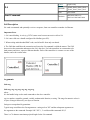
Embedded/Galil-centric Programming
In this approach, a host computer is only used during development to program the controller. The program is
then downloaded and burned to non-volatile flash using the #AUTO automatic subroutine to indicate where
code execution should start on boot-up. The Galil controller will now run "standalone," not requiring
any intervention from the host. Note that for serial and Ethernet controllers, the standalone controller can
still actively work with other controllers in a network, without host intervention.
PCI and other PC bus-based controllers support this approach, although still require the PCI bus for power.
GalilTools (GT) is provided as a programming environment for developing embedded applications.
Host-centric Programming
If a GUI or other frontend is desired to be run on a host, all development can be conducted on the host PC, with
the architecture, operating system, and programming language of choice. In this approach, the controller
receives every command from the host PC, nothing is running embedded. Many Galil firmware features
are available to facilitate host-centric programming including mode-of-motion buffers, data logging
buffers, asynchronous data record updates from the controller, PCI and UDP interrupt events, and more.
GalilTools (GT) is bundled with a programming library (API) for programming applications from a host.
Many popular operating systems and languages are supported.
Hybrid Programming
Perhaps the most versatile approach to Galil system design, the Hybrid approach allows for both embedded
code and host-side code to work in tandem. Typically an application is developed for embedded use in DMC
code. The code incorporates all of the detail of an application but relies on the host to provide it data.
Through variables, arrays, and other commands, the host is able to define the bounds of the embedded
algorithms. The host plays a supervisory role, interrogating status, receiving asynchronous updates from
the controller, starting and stopping threads, and so on. The controller takes care of the motion and I/
O responsibilities based on its embedded program, and the controller's real time operating system (RTOS)
ensures that the application won't suffer from indeterminacy which is common on general purpose PC
operating systems (e.g. Microsoft Windows). Because the controller takes care of the details, the host is able to
use its resources on other tasks, such as complicated number crunching or user interface.
It is noteworthy that Galil Standalone controllers (e.g. DMC-40x0, DMC-41x3, DMC-21x3, RIO-47xxx)
can leverage the Ethernet to provide powerful modularity. Using any of the above three system
approaches, multiple controllers can work in concert to achieve an application's requirements.
Networked controllers also provide easy scalability. Need some more digital or analog I/O? Add an RIO.
Need another axis of control? Add another DMC to the network. Both the Galil firmware and the Galil
software libraries provide features which allow easy use of multiple controllers on an Ethernet
network. RS232/422/485 networks are also possible.
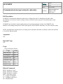
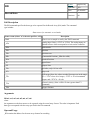
Bottom Up: Anatomy of DMC code
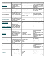
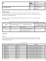
Classification
DMC language can be broken up into the following general classifications
Classification
Description
Examples
Example Comments
Explicit Only
The command receives its
arguments only by
assignment with the "="
operator.
IHC=192,168,1,101<1070>2
Create a TCP connection on
Ethernet handle C to a device
at IP address 192.168.1.101
on port 1070
Implicit Only
The command receives its
arguments only by an
implicit argument order.
IA 192,168,1,102
Set the local IP address to
192.168.1.102
Explicit or Implicit
The command receives its
arguments either by an
explicit assignment using
the "=" symbol, or an
implicit argument order.
KPA=64;KPB=32;KPH=128
KP 64,32,,,,,,128
Assign the proportional
constant (KP) of the PID
filter to three different axes.
Accepts Axis Mask
The command receives its
arguments as a string of
valid axis names.
ST ADF
Stop (ST) axes A, D and F.
Leave other axes running.
Two Letter Only
The command accepts no
arguments
BN
Burn (BN) controller
parameters to flash memory
Operator or Comparator
Operators take two
arguments and produce a
result. Comparators take
two values and return a
Boolean (1 or 0).
+,-,*,/
=,<,>,<=,>=,<>
Operators
Comparators
At Function
Starting with the @
character, these functions
take one argument and
perform a function,
returning its result
@SIN,@ASIN
@AN,@IN
@RND,@FRAC,@COM
Trig functions Sine and
ArcSine
I/O functions Analog in and
Digital in
Numerical functions Round,
Fractional Part, Bitwise
complement
Embedded Only
Not valid from the
terminal, or from PC-side
code, these commands are
used in embedded DMC
code only
IF,ELSE,ENDIF
JS,JP
EN, RE
IF Conditionals
Jump commands
End program, Return from
Error
Operand
Operands hold values, and
are not valid on their own.
They can be used as
arguments to commands,
operators or comparators
_TPA
_LFC
_TC
Current position of axis A
encoder
Forward limit state on C axis
Current Error code
Trippoint
Trippoints hold up a
thread's execution (block)
WT 1000
until a certain condition
AMA
occurs. These are a special
AI1
case of Embedded Only
type commands.
Wait 1000 ms
Wait until axis A completes
profiled motion
Wait for input one to go high
Comments are used to
document code.
Comment
'This is a comment
There are three types of
comments: REM, ', and NO
DMC code is case sensitive. All Galil commands are uppercase. User variables and arrays can be upper-case
or lower case. Galil recommends that array and variable names contain at least one lower-case character to
help distinguish them from commands.
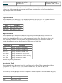
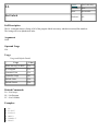
Explicit Notation
These commands specify data using an axis designator followed by an equals sign. The * symbol can be used
in place of the axis designator. The * defines data for all axes to be the same. For example:
Syntax
Description
PRB=1000
Sets B axis data at 1000
PR*=1000
Sets all axes to 1000
Implicit Notation
These commands require numerical arguments to be specified following the instruction. Values may be
specified for any axis separately or any combination of axes. The comma delimiter indicates argument
location. For commands that affect axes, the order of arguments is axis A first, followed by a comma, axis B
next, followed by a comma, and so on. Omitting an argument will result in two consecutive commas and
doesn't change that axis' current value. Examples of valid syntax are listed below.
Valid Syntax
Description
AC n
Specify argument for A axis only
AC n,n
Specify argument for A and B only
AC n,,n
Specify argument for A and C only
AC n,n,n,n
Specify arguments for A,B,C,D axes
AC ,n,,,n
Specify arguments for B and E axis only
AC ,,,n,n
Specify arguments for E and F
Where n is replaced by actual values.
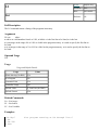
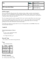
Accepts Axis Mask
These commands require the user to identify the specific axes to be affected. These commands are followed
by uppercase X,Y,Z and W or A,B,C,D,E,F,G and H. In DMC code, X,Y,Z,W and A,B,C,D are
synonyms, respectively.
No commas are used and the order of axes is not important. When an argument is not required and is not given,
the command is executed for all axes.
Valid Syntax
SH A
Description
Servo Here, A only
SH ABD
Servo Here, A,B and D axes
SH ACD
Servo Here, A,C and D axes
SH ABCD
Servo Here, A,B,C and D axes
SH XYZW
Identical to SH ABCD
SH BCAD
Servo Here, A,B,C and D axes
SH ADEG
Servo Here, A,D,E and G axes
SH H
Servo Here, H axis only
SH
Servo Here, all axes
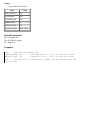
Two Letter Only
These commands have no options or arguments. Some examples follow.
Valid Syntax
Description
BN
Burn parameters
BV
Burn Variables
BP
Burn Programs (not applicable on the DMC30000)
ID
Identify hardware configuration
LA
List arrays
Operator or Comparator
Operators and Comparators take two arguments and return one value. All comparison and operations occur left
to right. That is, multiplication and addition have the same order-of-operation priority, and operations
and comparisons are performed as encountered on a left to right search. Parenthesis should be used to
indicate order of operation precedence. Some examples follow.
Valid Syntax
Description
var = 1 + 1
Variable var is assigned value 2
var = 2 + 1 * 3
Variable var is assigned value 9
var = 2 + (1 * 3)
Variable var is assigned value 5
IF ((a=b) & (a=c))
Checks if a=b=c
IF (a=b=c)
Invalid syntax to check if a=b=c
var = (a=1)
var is assigned with Boolean value (true/false) based on comparison a=1
At Function
At functions take one value or evaluated expression and return a result. Some examples follow.
Valid Syntax
Description
var = @SIN[90]
Variable var is assigned value 1. Sine of 90 degrees.
var = @ASIN[1]
Variable var is assigned value 90. Inverse Sine of 1
var = @IN[1]
Variable var is assigned 1 or 0, based on current state of digital input 1
var = @RND[1 + 0.6]
Variable var is assigned 2, 1.6 round to the nearest integer
Embedded Only
Embedded commands make sense only in the context of an embedded application. These commands
include jumps, if-then-else syntax, subroutines, etc. Some examples follow.
Valid Syntax
Description
#go
Labels can be called by name in order to jump code to specific
lines
JP#go
Jump to line number indicated by #go label
#AUTO
Automatic subroutine. #AUTO is the entry point for execution on
bootup. See entries starting with # for other automatic subroutines.
RI
Return from interrupt. This is the termination for certain
automatic subroutines (event handlers)
IF (a=5);MG"Five";ELSE;MG"Not Five";ENDIF
If statement. ; can be replaced by carriage return for better
readability
Automatic subroutines operate very similarly to event handlers in event-driven languages. When an event
occurs, execution of code jumps to the automatic subroutine. Once the end of the automatic subroutine is
reached, code execution continues where it left off.
Operand
Many commands have corresponding operands that can be used for interrogation or for use within mathematical
or other expressions. Operands are not valid alone, and must be used inside a valid DMC code expression.
For example, to print the value of the TIME operand the following command is issued.
:MG TIME
13779546.0000
:
To assign TIME to a variable and then print it, the following is used.
:var=TIME
:MG var
13909046.0000
:
All DMC codes starting with the underscore _ character are operands. The servo loop counter, TIME, is an
operand without an underscore.
Variables and array elements act similarly to operands. Whereas operands are read-only, variables and
array elements are read-write. Operands, variables, and array elements can be arguments to commands, are valid
in mathematical expressions, and can be used in assignments to other variables and array elements.
Trippoints
The controller provides several commands that can be used to pause execution of code until certain conditions
are met. Commands of this type are called "trippoints." Such trippoints may wait for an elapsed time, wait for
a particular input, or in motion controllers wait for particular motion event to occur.
When a trippoint command is executed, the program halts execution of the next line of code until the status of
the trippoint is cleared. Note that the trippoint only halts execution of the thread from which it is
commanded while all other independent threads are unaffected. Additionally, if the trippoint is commanded from
a subroutine, execution of the subroutine, as well as its calling thread, is halted.
Trippoints are intended for use only within embedded DMC code and should not be sent from a terminal
or a host application program executing from a PC.
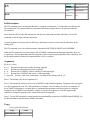
Popular Trippoints
Trippoint
Short Description
Supported On
WT
wait for a time period (sleep)
All Galil Hardware
AI
wait for a digital input
All Galil Hardware
AM
after move
Motion Controllers
MC
motion complete, in position
Motion Controllers
AT
At time, time from reference
All Galil Hardware
AD
after distance
Motion Controllers
AS
At speed
Motion Controllers
AV
After Vector Distance
Motion Controllers
AA
After Analog
RIO-47xxx only
Comments
Comments are used to document code, and to disable lines of code while debugging. There are three ways
to comment.
REM REM stands for "Remark." When a line begins with the REM command, the entire line is stripped
by Galil software before downloading to the controller. REM is NOT a recognized Galil command; it is a
keyword recognized by Galil software as data that is to be skipped during program download. When
program speed and code length are at a premium, use REM comments.
NO NO stands for "No Operation." Lines beginning with NO are downloaded to the controller and incur a
non-zero processing overhead as a result. If the developer desires the comments to stay in code so that
uploaded code will still be notated, use NO or '. NO comments are not stripped when code is compressed
by software.
' The single quote character is similar to NO. Lines beginning with ' are downloaded to the controller and
incur a non-zero processing overhead as a result. If the developer desires the comments to stay in code so
that uploaded code will still be notated, use NO or '. ' comments ARE stripped when code is compressed
by software.
When commenting inline, NO and ' are valid when preceded by a ; character. REM is only valid as the start of
a line. Some examples follow.
BG;'
This is a comment. semicolon and ' precede, followed by spaces,
and then the comment
ST;NO Same as above, except on compression, this data will remain,
less spaces
REM This is a remark. It will not be downloaded to the controller by
Galil software
NO This is an NO comment starting a line
NOTE This is also an NO comment
' This is a single quote comment starting a line
'PRX=1000;BGX;' This line of code has been disabled with a leading '
Special characters ; and `
; The semicolon is used to separate individual commands on a single line of embedded code or in a
single interrogation from the host. When running multi-threaded, embedded code, all commands on a single
line will be executed before the program counter switches to the next thread*. Using multiple commands on
a single line therefore allows for increased thread priority.
* Certain commands such as trippoints will cause the program counter to continue to the next thread before a line has completed.
' On the RIO series of PLCs and the DMC30000, the backtick (ascii 96) is a line continuation character. If
a line of code passes the controller's 40 character length limit, the ` character can be used to continue the code
on the next line.
Interrogation
Most commands accept a question mark (?) as an argument. This argument causes the controller to
return parameter information. Type the command followed by a ? for each axis requested. The syntax format is
the same as the parameter arguments described above except '?' replaces the values.
Syntax
Description
PR ?
The controller will return the PR value for the A axis
PR ,,,?
The controller will return the PR value for the D axis
PR ?,?,?,?
The controller will return the PR value for the A,B,C and D axes
PR ,,,,,,,?
The controller will return the PR value for the H axis
PR*=?
The controller will return the PR value for all axes
Data Types
Galil4.2
There is only one native data type in DMC language, the Galil4.2 format. Galil4.2 is a signed, fixed-point,
decimal number with 4 bytes of integer and 2 bytes of fraction. Bit encoding of Galil4.2 is 2's complement.
Integer values range from -2,147,483,648 to 2,147,483,647
Fractional values range from 0.999985 to .000015 in increments of .000015 (one part in 65535). When
working with very small fractional values, use the $ formatter to display the number in hex.
:v=1-$0.0001;'subtract the smallest fractional value
:v=?
1.0000
:v=?{$1.4};'hex display has higher resolution
$0.FFFF
:v=v+$0.0001
:v=?
1.0000
:v=?{$1.4}
$1.0000
:
Strings
Galil "strings" are still variables in 4.2 format, with each byte printed as the ASCII representation of the
number. Galil strings are max 6 characters. The left most character of a string is the most significant byte in
the Galil4.2 number.
Boolean
A Boolean is represented in the Galil language as a Galil4.2 value. 0.0 is false. All other values are true.
:a=1
:b=2
:c=(a=b);'(a=b) returns a Galil Boolean
:LV
a= 1.0000
b= 2.0000
c= 0.0000
:a=2
:c=(a=b)
:LV
a= 2.0000
b= 2.0000
c= 1.0000
:
Units of Distance
The units of distance in a Galil controller are either in "counts" or "steps". A count is a single unit of
feedback, such as a quadrature count, an SSI or BiSS bit, or an Analog to Digital converter bit. Counts are
typical with servos. Steps are used for stepper-type motors. Steps are open-loop units and refer to a single
level transition sent to a stepper amplifier. In general for a unit of real distance, 1 step is NOT equal in distance
to 1 count. See the "Stepper Position Maintenance Mode" in the user manual for more information.
Each axis of a Galil motion controller can be configured to control either a servo or a stepper. In
this documentation, servo motors are generally assumed. Differences between functionality in stepper and
servo operation are noted in each command. Where not explicitly noted otherwise, when using stepper motors,
the unit "count" can be exchanged with the unit "step" (e.g. steps per second instead of counts per second).
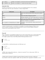
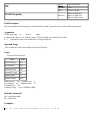
Flash Memory
Each Galil controller has a flash memory provided for saving parameters and user data. The flash is divided
into three sectors, Parameters, Variables and Arrays, and Program. Each sector has an associated burn
command which burns the entire sector.
Flash Sector
Data Storage
Burn Command
Parameters
Stores the controller parameters such as PID filter coefficients, IP address,
BN
motion kinematic values, I/O configurations
Variables and Array
Stores the currently allocated variable table (LV) and each of the arrays in
BV
the array table (LA)
Program
Stores program currently downloaded on the controller*
BP
*The DMC30000 downloads and runs programs directly out of flash. BP is not applicable.
Resetting the Controller to Factory Defaults
When a master reset occurs, the controller will reset all setup parameters to their default values and the
non-volatile memory is cleared to the factory state. A master reset is executed by the
command, <ctrl R> <ctrl S> <Return> OR by powering up or resetting the controller with the MRST jumper on.
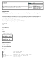
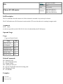
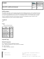
Subtraction Operator
Syntax:
Operator or Comparator
Operands:
none
Burn:
not burnable
Hardware:
All
Full Description
The - symbol is the subtraction operator. It takes as arguments any two values, variables, array elements,
operands, or At functions (@SIN[]) and returns a value equal to the difference of the arguments.
This is a binary operator (takes two arguments and returns one value).
Mathmatical operations are calculated left to right rather than multiplication and division calculations
performed prior to addition and subraction.
Example:
1+2*3 = 9;'
not 7
It is recommended that parenthesis be used when more than one mathmatical operation is combined in
one command.
Example:
var = ((10*30)+(60/30));'
evaluates as 302
var = 10*30+60/30;'
evalutes as 12
Arguments
m-m
where m is any value, variable, array element, operand, or At functions (@SIN[])
The result of this operation is a value, which is not valid on its own. It must be coupled with a command.
See examples below.
Operands
N/A
Usage
Usage and Default Details
Usage
Value
While Moving
Yes
In a Program
Yes
Command Line
Yes
Default Value
N/A
Related Commands
N/A
Examples
:var1 = 10-4
:var2 = var1 - 3
:MG var2 - 1
2.0000
:
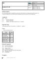
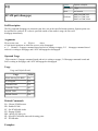
#
Label (subroutine)
Syntax:
Other
Operands:
none
Burn:
not burnable
Hardware:
All
Full Description
The # operator denotes the name of a program label (for example #Move). Labels can be up to seven
characters long and are often used to implement subroutines or loops. Labels are divided into (a) user defined
(b) automatic subroutines. User defined labels can be printed with LL and the number of labels left available
can be queried with MG _DL. The automatic subroutines include #CMDERR, #LIMSWI, #POSERR,
#ININT, #AUTO, #AUTOERR, and #MCTIME (no RIO).
A label can only be defined at the beginning of a new line.
There is a maximum of 510 labels available.
Arguments
#string
where
string is a label name up to seven characters. Uppercase or lowercase characters are valid.
Operand Usage
N/A
Usage
Usage and Default Details
Usage
Value
While Moving (no RIO)
Yes
In a Program
Yes
Command Line
No
Controller Usage
All
Default Value
N/A
Default Format
N/A
Related Commands
LL - List labels
_DL - Labels available
JP - Jump statement
JS - Jump subroutine
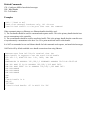
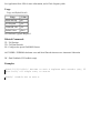
Examples:
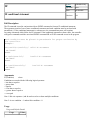
'A simple example of iteration. The loop will run 10 times
i=0;'
Create a counter
#Loop;'
Label
i=i+1;'
Increment counter
JP#Loop, i<10;' spin in #Loop until i >= 10
EN;'
End the subroutine or thread
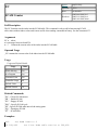
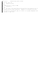
#AMPERR
Amplifier error automatic subroutine
Syntax:
Other
Operands:
none
Burn:
not burnable
Hardware:
DMC40x0 DMC41x3
DMC21x3 DMC300x0
Full Description
#AMPERR is an automatic subroutine and is used to run code when a fault occurs on a Galil amplifier. See the
TA command and individual amplifier information in the controller user manual.
Other user code does not need to be running for #AMPERR to be raised.
When an external servo driver is used in an axes where the AMP-430x0 is also installed, the axis should be
setup as a brushed motor (BR~a=1) otherwise the lack of hall inputs will cause an amplifier error.
Use RE to return from the AMPERR subroutine.
See the TA command for more information.
Arguments
N/A
Operand Usage
N/A
Usage
Usage and Default Details
Usage
Value
While Moving
Yes
In a Program
Yes
Command Line
No
Controller Usage
controllers with integrated drives
Related Commands
TA - Tell amplifier status
CN - Configure I/O
OE - Off on error
RE - Return from error
Examples:
'this code will run in the event of an amplifer error,
'setting a digital output and notifying the operator.
#AMPERR
'Set a digital bit to signal an amplifier error to peripheral hardware
SB4
'Send a message to the user
MG"An amplifier error has occured"
'Return from the AMPERR subroutine, restoring trippoints that were running
RE1
Detailed #AMPERR example. Uses LCD to display amplifier error
information and remains in #AMPERR routine until the error is cleared.
#AMPERR
REM mask out axes that are in brushed mode for _TA1
mask=(_BRH*128)+(_BRG*64)+(_BRF*32)+(_BRE*16)+(_BRD*8)+(_BRC*4)+(_BRB*2)+_BRA
mask=@COM[mask]
mask=((_TA1&mask)&$0000FFFF)
LU0;'turn off auto update of LCD
REM amplifier error status on LCD
MG"A-ER TA0"{L1},_TA0{L2};WT2000
MG"A-ER TA1"{L1},mask{L2};WT2000
MG"A-ER TA2"{L1},_TA2{L2};WT2000
MG"A-ER TA3"{L1},_TA3{L2};WT2000
LU1;'turn on Automatic Axis Update of LCD
WT5000
REM the sum of the amperr bits should be 0 with no amplifier error
er=_TA0+mask+_TA2+_TA3
JP#AMPERR,er0
REM Notify user amperr has cleared
LU0
MG"AMPERR"{L1},"RESOLVED"{L2}
WT3000
LU1
RE
#AUTO
Subroutine to run automatically upon power up
Syntax:
Other
Operands:
none
Burn:
not burnable
Hardware:
All
Full Description
#AUTO defines code to run automatically when power is applied to the controller, or after the controller is
reset. When no host software is used with the controller, #AUTO and the BP command are required to run
an application program on the controller.
Upon controller startup, application code will automatically begin running in thread 0 at #AUTO.
Use EN to end the routine.
Arguments
N/A
Operand Usage
N/A
Usage
Usage and Default Details
Usage
Value
While Moving
Yes
In a Program
Yes
Command Line
No
Controller Usage
All
Related Commands
EN - End program
#AUTOERR - Automatic Subroutine for EEPROM error
BP - Burn program
Examples:
'On startup, this code will create a 50% duty cycle square wave on output
1 with a period of 1 second.
#AUTO;'
Start on powerup
SB1;'
Set bit 1
WT500;'
Wait 500msec
CB1;'
Clear bit 1
WT500;'
JP#AUTO;'
Wait 500msec
Jump back to #AUTO
#AUTOERR
EEPROM checksum error and Serial Encoder timeout error
Automatic Subroutine
Syntax:
Other
Operands:
none
Burn:
not burnable
Hardware:
All
Full Description
All firmware versions and controllers
#AUTOERR will run code upon power up if data in the EEPROM has been corrupted. The EEPROM
is considered corrupt if the checksum calculated on the bytes in the EEPROM do not match the checksum
written to the EEPROM. The type of checksum error can be queried with _RS
Use EN to end the routine.
-SER firmware
#AUTOERR will also run if the time to acquire serial position data exceeds 90% of the hardware sample
loop. This type of error is very rare and should never occur in normal operation.
In the event of a serial position acquisition timeout, the following will occur:
a. The controller will reset
b. The controller servo loop will not run, TM will be set to zero
c. TC1 will return "143 TM timed out"
d. The automatic subroutine #AUTOERR will run, if present
e. The Error output will be set.
When using serial encoders (SSI or BiSS), the #AUTOERR should follow these guidlines:
a. IF _TC=143 do not employ any trippoints in following code as the timer interrupt is suspended.
b. Serial encoders can be disabled with the commands SIn=0 or SSn=0 where n is the axis indicator
ABCDEFG or H
c. In order to re-enable the timer interrupt issue "TM m" where m is the servo update period in us
(usually m=1000).
See code example below.
Arguments
N/A
Operand Usage
N/A
Usage
Usage and Default Details
Usage
Value
While Moving
Yes
In a Program
Yes
Command Line
No
Controller Usage
All
Default Value
N/A
Default Format
N/A
Related Commands
_RS - Checksum error code operand
EN - End program
Examples:
'Code detects a checksum error and notifies the user
#AUTOERR
MG"EEPROM ERROR ",_RS
EN
'Distinguishing between a serial timeout
' condition and an EEProm condition
#AUTOERR
IF _TC=143
REM BiSS or SSI timeout
REM No trippoints in this clause
REM Print message to DMC-4020 LCD
LU0
MG"BiSS"{L1}
MG"Timeout"{L2}
SSA=0
SSB=0
ELSE
REM Checksum error
REM trippoints ok here
REM Print message to DMC-4020 LCD
LU0
MG"EEProm:"{L1}
MG{Z10.0}_RS{L2}
ENDIF
EN
#CMDERR
Command error automatic subroutine
Syntax:
Other
Operands:
none
Burn:
not burnable
Hardware:
All
Full Description
#CMDERR is an automatic subroutine that runs code when a DMC code error occurs.
Without #CMDERR defined, if an error (see TC command) occurs in an application program running on the
Galil controller, the program (and all threads) will stop.
Use EN to end the routine.
#CMDERR will only run from errors generated within embedded DMC code.
In a single threaded application (Thread 0 only), the EN command in the #CMDERR routine will restart thread
0 where it left off.
In a multi-threaded application, the thread that has an error will be halted when a command error occurs. Thread
0 will be interrupted to run the #CMDERR routine but other threads will continue to run. In order to restart
the thread that encountered the error, see the example in Chapter 7 of the User Manual and the _ED
operand. Thread 0 does not need to be running in order for the #CMDERR routine to execute.
Arguments
N/A
Operand Usage
N/A
Usage
Usage and Default Details
Usage
Value
While Moving
Yes
In a Program
Yes
Command Line
No
Controller Usage
All
Related Commands
TC - Tell Error Code
_ED - Last program line with an error
EN - End program
Examples:
'This code will put the motion controller in Position Tracking mode.
'Variable "target" is updated from the terminal or from a host program
'to specify a new target. #CMDERR is used to detect a bad target value.
#start
DPA=0;'
Define current position as zero
PTA=1;'
Turn on position tracking
target=0;'
Initialize target variable
#track;'
Start tracking
PAA=target;' Track to current value of target
WT500;'
Wait 500 ms
JP#track;'
Continue to track
'
'
#CMDERR;' runs if an error occurs
JP#done,_TC<>6 ;'check that an out of range occured (See TC)
MG"Value ",target," is out of range for Position Tracking"
target=_PAA ;' reset target
#done
EN1 ;'return to tracking logic
#COMINT
Communication interrupt automatic subroutine
Syntax:
Other
Operands:
none
Burn:
not burnable
Hardware:
DMC40x0 DMC41x3
DMC21x3 RIO
DMC300x0
Full Description
#COMINT is an automatic subroutine which can be configured by the CI command to run either when
any character is received, or when a carriage return is received over the com port. The auxiliary port is used
if equipped.
#COMINT runs in thread 0, and an application must be running in thread 0 in order for #COMINT to be
enabled. Code running in thread zero will be interrupted by the #COMINT subroutine. Use EN to end the routine
NOTE: An application program must be executing for the automatic subroutine to function, which runs in thread
0. Use EN to end the routine.
Arguments
N/A
Operand Usage
N/A
Usage
Usage and Default Details
Usage
Value
While Moving
Yes
In a Program
Yes
Command Line
No
Controller Usage
All
Default Value
N/A
Default Format
N/A
Related Commands
P2CD - Serial port 2 code
P2CH - Serial port 2 character
P2NM- Serial port 2 number
P2ST - Serial port 2 string
CI - Configure #COMINT
CC - Configure serial port 2
EN - End subroutine
Examples:
#A;
CC9600,0,1,0
CI2;
#Loop
MG "Loop";
WT 1000
JP#Loop
#COMINT
MG "COMINT:", P2CH{S1};
EN1,1;
points that
'
'Program Label
'interrupt on any character
'print a message every second
'print a message and the received character
' End this subroutine, re-arming trip
were running and re-enabling the CI mask
#ININT
Input interrupt automatic subroutine
Syntax:
Other
Operands:
none
Burn:
not burnable
Hardware:
DMC40x0 DMC41x3
DMC21x3 RIO DMC18x6
DMC18x2 DMC300x0
Full Description
#ININT is an automatic subroutine that runs upon a state transition of digital inputs 1 to 8 and is configured
with II. #ININT runs in thread 0.
To make an unconditional jump from #ININT, there are two methods for re-enabling the interrupt capability: 1)
re-issue the command II, or 2) use a 'null' routine. The ?null? routine allows for the execution of the RI
command before the unconditional jump.
For more information see Application Note #2418
http://www.galilmc.com/support/appnotes/optima/note2418.pdf
Arguments
N/A
Operand Usage
N/A
Usage
Usage and Default Details
Usage
Value
While Moving
Yes
In a Program
Yes
Command Line
No
Related Commands
II- Input interrupt
@IN - Read digital input
RI - Return from interrupt
Examples:
II1;
EN;
'
#ININT;
MG"Inputs:",_TI0;
WT100;
'arm digital input 1
'End thread zero
'Automatic sub. Runs on input event
'Display status of inputs 1-8
'Debounce input
RI;
'Return from interrupt
#LIMSWI
Limit switch automatic subroutine
Syntax:
Other
Operands:
none
Burn:
not burnable
Hardware:
DMC40x0 DMC41x3
DMC21x3 DMC18x6
DMC18x2 DMC300x0
Full Description
Without #LIMSWI defined, the controller will effectively issue the STn on the axis when it's limit switch
is tripped. With #LIMSWI defined, the axis is still stopped, and in addition, code is executed. #LIMSWI is
most commonly used to turn the motor off when a limit switch is tripped (see example below). For #LIMSWI
to run, the switch corresponding to the direction of motion must be tripped (forward limit switch for
positive motion and negative limit switch for negative motion). #LIMSWI interrupts thread 0 when it runs.
Use RE to terminate the #LIMSWI subroutine.
Arguments
N/A
Operand Usage
N/A
Usage
Usage and Default Details
Usage
Value
While Moving
Yes
In a Program
Yes
Command Line
No
Controller Usage
All
Dafault Value
N/A
Default Format
N/A
Related Commands
_LFn - State of forward limit switch
_LRn - State of reverse limit switch
LD - Limit Disable
Examples:
#Main
MG "Main"
;'print a message every second
WT1000
JP#Main
EN
'
#LIMSWI ;'runs when a limit switch is tripped
IF (_LFX = 0) | (_LRX = 0)
MG "X"
DCX=67107840
STX
AMX
MOX
ELSE; IF (_LFY = 0) | (_LRY = 0)
MG "Y"
DCY=67107840
STY
AMY
MOY
ENDIF; ENDIF
RE1
#MCTIME
MC command timeout automatic subroutine
Syntax:
Other
Operands:
none
Burn:
not burnable
Hardware:
DMC40x0 DMC41x3
DMC21x3 DMC18x6
DMC18x2 DMC300x0
Full Description
#MCTIME runs when the MC command is used to wait for motion to be complete, and the actual position TP
does not reach or pass the target within the specified timeout TW.
Use EN to terminate the subroutine.
Arguments
N/A
Operand Usage
N/A
Usage
Usage and Default Details
Usage
Value
While Moving
Yes
In a Program
Yes
Command Line
No
Controller Usage
All
Default Value
N/A
Default Format
N/A
Related Commands
MC - Wait for motion complete trip point
TW - MC timeout
Examples:
#BEGIN;'
TWX=1000;'
PRX=10000;'
BGX;'
MCX;'
EN;'
'
Begin main program
Set the time out to 1000 ms
Position relative
Begin motion
Motion Complete trip point
End main program
#MCTIME;'
MG "X fell short";'
EN1;'
Motion Complete Subroutine
Send out a message
End subroutine
#POSERR
Position error automatic subroutine
Syntax:
Other
Operands:
none
Burn:
not burnable
Hardware:
DMC40x0 DMC41x3
DMC21x3 DMC18x6
DMC18x2 DMC300x0
Full Description
The factory default behavior of the Galil controller upon a position error (_TEn > _ERn) is to do nothing
more than drive the error signal low, turning on the red error LED. If OE is set to 1, the motor whose position
error (TE) equals or exceeds its threshold (ER) will be turned off (MO). #POSERR can be used if the
programmer wishes to run code upon a position error, for example to notify a host computer.
The #POSERR label causes the statements following to be automatically executed if error on any axis exceeds
the error limit specified by ER. The error routine must be closed with the RE command. The RE command
returns from the error subroutine to the main program.
Use RE to end the routine
#POSERR will also run when OE1 is set for an axes and that axis is also setup for encoder failure detection
(see OA, OT, OV commands).
The automatic subroutine runs in thread 0. If thread 0 is running, it will jump to #POSERR when an error
occurs. If thread 0 is not running, #POSERR will be started in thread 0.
Arguments
N/A
Operand Usage
N/A
Usage
Usage and Default Details
Usage
Value
While Moving
Yes
In a Program
Yes
Command Line
No
Controller Usage
All
Default Value
N/A
Default Format
N/A
Related Commands
OE - Off on error
TE - Tell error
ER - Error limit
RE - Return from error routine
Examples:
#main;'
'
JP #main
main program
REM simple example of #POSERR
#POSERR
MG "#POSERR"
RE
REM example of #POSERR that checks for position error on each axis
#POSERR
~a=0;'
axis designator
IF ((_TE~a>_ER~a)&(_OE~a))
MG "Position Error occured on ",~a{F1.0}," axis"
ENDIF
~a=~a+1
JP#POSERR,~a<_BV;' loop until axes have been checked
AI 1;'
wait until input 1 goes high (ex. safety switch)
SH
RE1;'
retrurn to main program
REM #POSERR example for checking to see if encoder failure occured
REM The stop code will only update of the profilier is running at the time
REM the encoder failure is detected.
#POSERR
~a=0
#loop
IF _MO~a=1
IF ((_TE~a<_ER~a)&(_OE~a)&(_OA~a))
MG "possible encoder failure on ",~a{Z1.0}," axis"
ENDIF
ENDIF
~a=~a+1
JP#loop,~a<_BV
AI1;'
wait for input 1 to go high
SH;'
enable all axes
RE
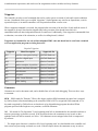
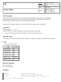
#SERERR
Serial Encoder Error Automatic Subroutine
Syntax:
Embedded Only
Operands:
none
Burn:
not burnable
Hardware:
DMC40x0 DMC41x3 RIO
DMC300x0
Full Description
When equipped with hardware featuring the -BiSS encoder upgrade, #SERERR is an automatic subroutine
which runs whenever there is a fault condition on the serial encoder. The following are the fault conditions
which will cause #SERERR to interrupt.
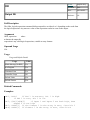
Serial Encoder Faults
BiSS
Encoder timeout (bit 0 of _SS)
CRC error (bit 1 of _SS)
Error bit* (bit 2 of _SS)
Warning bit* (bit 3 of _SS)
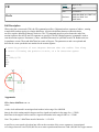
The active level of the Error and Warning bits for BiSS must be configured with SY.
For the encoder timeout condition, TC1 will also return "140 Serial encoder missing."
Return from this automatic sub with RE.
*Note: The encoder manufacturer may name the Error and Warning bits differently. Consult the
encoder documentation for the naming convention.
Galil defines the Warning bit as the bit directly preceeding the CRC. The Error bit is defined as the bit
directly preceeding the Warning bit. See table 1.
Arguments
N/A
Operands
N/A
Usage
Usage and Default Details
Usage
Value
While Moving
Yes
In a Program
Yes
Command Line
No
Default Value
N/A
Related Commands
SS - Configure the special Galil BiSS feature
SY - Serial encoder BiSS active level
Examples
#SERERR
LU0
MG"SERERR"{L1}
MG_SSA{L2}
REM disable axis A
OEA=1;ERA=0
REM disable axis serial encoder
SSA=0
RE
#TCPERR
Ethernet communication error automatic subroutine
Syntax:
Other
Operands:
none
Burn:
not burnable
Hardware:
DMC40x0 DMC41x3
DMC21x3 RIO
DMC300x0
Full Description
#TCPERR is an automatic subroutine which allows execution of code when an TCP error occurs.
The following error (see TC) occurs when a command such as MG "hello" {EA} is sent to a failed
Ethernet connection:
123 TCP lost sync or timeout
This error means that the client on handle A did not respond with a TCP acknowledgement (for example
because the Ethernet cable was disconnected). Handle A is closed in this case.
#TCPERR allows the application programmer to run code (for example to reestablish the connection) when
error 123 occurs.
Use RE to terminate the subroutine.
Code does not need to be running in thread zero for #TCPERR to run.
Arguments
N/A
Operand Usage
N/A
Usage
Usage and Default Details
Usage
Value
While Moving
Yes
In a Program
Yes
Command Line
No
Controller Usage
All
Related Commands
TC - Tell error code
_IA4 - Last dropped handle
MG - Print message
SA - Send ASCII command via Ethernet
Examples:
#L
MG {EA} "L"
WT1000
JP#L
#TCPERR
MG {P1} "TCPERR. Dropped handle", _IA4
RE
'NOTE: Use RE to end the routine
$
Hexadecimal
Syntax:
Other
Operands:
none
Burn:
not burnable
Hardware:
All
Full Description
The $ operator denotes that the following string is in hexadecimal notation.
Arguments
$nnnnnnnn.mmmm
n is up to eight hexadecimal digits (denoting 32 bits of integer)
m is up to four hexadecimal digits (denoting 16 bits of fraction)
Operand Usage
N/A
Usage
Usage and Default Details
Usage
Value
While Moving (No RIO)
Yes
In a Program
Yes
Command Line
Yes
Controller Usage
All
Default Value
N/A
Default Format
N/A
Related Commands
+ - * / % - Multiply (shift left)
+ - * / % - Divide (shift right)
MG {$8.4} - Print in hexadecimal
Examples:
x = $7fffffff.0000
;'store 2147483647 in x
y = x & $0000ffff.0000
;'store lower 16 bits of x in y
z = x & $ffff0000.0000 / $10000 ;'store upper 16 bits of x in z
%
Modulo Operator
Syntax:
Operator or Comparator
Operands:
none
Burn:
not burnable
Hardware:
DMC40x0 DMC41x3 RIO
DMC18x6 DMC300x0
Full Description
The % symbol is the modulo operator. It takes as arguments any two values, variables, array elements,
operands, or At functions (@SIN[]) and returns a value equal to the modulo of the arguments.
This is a binary operator (takes two arguments and returns one value).
Mathmatical operations are calculated left to right rather than multiplication and division calculations
performed prior to addition and subraction.
Example:
1+2*3 = 9, not 7
It is recommended that parenthesis be used when more than one mathmatical operation is combined in
one command.
Example:
var = ((10*30)+(60/30));'
evaluates as 302
var = 10*30+60/30;'
evalutes as 12
Arguments
m%m
where m is any value, variable, array element, operand, or At functions (@SIN[])
The result of this operation is a value, which is not valid on its own. It must be coupled with a command.
See examples below.
Operands
N/A
Usage
Usage and Default Details
Usage
Value
While Moving
Yes
In a Program
Yes
Command Line
Yes
Default Value
N/A
Related Commands
N/A
Examples
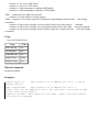
'Determine the day of week in n days
DM name[7];'Strings for day of week
name[0]="SUN"
name[1]="MON"
name[2]="TUE"
name[3]="WED"
name[4]="THU"
name[5]="FRI"
name[6]="SAT"
today=2;'Tuesday
days=123;'Days from now
dow=((days + today)%7);'calculate future day of week
MG"The day of week in ",days{Z10.0}," days will be ", name[dow]{S3.0}
EN
REM Code Returns: The day of week in
123 days will be SAT
&
Bitwise AND Operator
Syntax:
Operator or Comparator
Operands:
none
Burn:
not burnable
Hardware:
All
Full Description
The & symbol is the bitwise AND operator used with IF, JP, and JS decisions, and also to perform
bitwise ANDING of values.
Arguments
m&m
where
m is any value, operand, variable, array element, or At Function
For IF, JP, and JS, the values used for m are typically the results of logical expressions such as (x > 2) & (y=8)
The result of this operation is a value, which is not valid on its own. It must be coupled with a command.
See examples below.
Operands
N/A
Usage
Usage and Default Details
Usage
Value
While Moving
Yes
In a Program
Yes
Command Line
Yes
Default Value
Yes
Related Commands
N/A
Examples
'Bitwise use
var1=$F;'00001111
var2=$F0;'1111000
MG (var1 & var2)
EN
REM Returned: 0.0000
'Conditional Use
var1=$F;'00001111
var2=$F0;'1111000
IF (var1 = $F) & (var2 = $F1)
MG"True"
ELSE
MG"False"
ENDIF
EN
REM Returned: False
&
JS subroutine pass variable by reference
Syntax:
Other
Operands:
none
Burn:
not burnable
Hardware:
DMC40x0 DMC41x3
DMC18x6 DMC300x0
Full Description
The & symbol is used to pass a variable by reference on the subroutine stack. When passed by reference, a
change to the local-scope variable is changes the global value.
Arguments
JS#label(&var1,&var2,&var3,&var4,&var5,&var6,&var7,&var8)
where
#label is the label for the subroutine to call
var1 - var8 are the names of global variables which have already been dimensioned. If a value changes in
the #label subroutine, the value of the global variable will also be change.
To ensure that the global variable does not get changed, omit the & symbol to send a copy of the variable to
the stack.
Operands
N/A
Usage
Usage and Default Details
Usage
Value
While Moving
Yes
In a Program
Yes
Command Line
NO
Default Value
N/A
Related Commands
N/A
Examples
Pass By Reference Example:
#main
value=5;'
a value to be passed by reference
global=8;'
a global variable
JS#SUM(&value,1,2,3,4,5,6,7);' note first arg passed by reference
MG value;'
message out value after subroutine.
MG _JS;'
message out returned value
EN
'
#SUM;'
(* ^a,^b,^c,^d,^e,^f,^g)
^a=^b+^c+^d+^e+^f+^g+^h+global
EN,,^a
'notes'do not use spaces when working with ^
'If using global variables, they MUST be created before the subroutine is run
Executed program from program2.dmc
36.0000
36.0000
(,)
Parentheses (order of operations)
Syntax:
Other
Operands:
none
Burn:
not burnable
Hardware:
All
Full Description
The parentheses denote the order of math and logical operations. Note that the controller DOES NOT
OBEY STANDARD MATHEMATICAL OPERATOR PRECEDENCE. For example, multiplication is
NOT evaluated before addition. Instead, the controller follows left-to-right precedence. Therefore, it is required
to use parentheticals to ensure intended precedence.
Arguments
(n) where
n is a math (+ - * /) or logical (& |) expression
Operand Usage
N/A
Usage
Usage and Default Details
Usage
Value
While Moving (No RIO)
Yes
In a Program
Yes
Command Line
Yes
Controller Usage
All
Default Value
N/A
Default Format
N/A
Related Commands
+ - * / - Math Operators
& | - Logical Operators
Examples:
:MG 1 + 2 * 3
9.0000
:MG 1 + (2 * 3)
7.0000
*
Multiplication Operator
Syntax:
Operator or Comparator
Operands:
none
Burn:
not burnable
Hardware:
All
Full Description
The * symbol is the multiplication operator. It takes as arguments any two values, variables, array
elements, operands, or At functions (@SIN[]) and returns a value equal to the product of the arguments.
This is a binary operator (takes two arguments and returns one value).
Mathmatical operations are calculated left to right rather than multiplication and division calculations
performed prior to addition and subraction.
Example:
1+2*3 = 9;'
not 7
It is recommended that parenthesis be used when more than one mathmatical operation is combined in
one command.
Example:
var = ((10*30)+(60/30));'
evaluates as 302
var = 10*30+60/30;'
evalutes as 12
Arguments
m*m
where m is any value, variable, array element, operand, or At functions (@SIN[])
The result of this operation is a value, which is not valid on its own. It must be coupled with a command.
See examples below.
Operands
N/A
Usage
Usage and Default Details
Usage
Value
While Moving
Yes
In a Program
Yes
Command Line
Yes
Default Value
N/A
Related Commands
N/A
Examples
:var1 = (2 + 3) * 2
:var2 = var1 * 10
:MG var2 * 0.5
50.0000
:
/
Division Operator
Syntax:
Operator or Comparator
Operands:
none
Burn:
not burnable
Hardware:
All
Full Description
The / symbol is the division operator. It takes as arguments any two values, variables, array elements, operands,
or At functions (@SIN[]) and returns a value equal to the quotient of the arguments.
This is a binary operator (takes two arguments and returns one value).
Mathmatical operations are calculated left to right rather than multiplication and division calculations
performed prior to addition and subraction.
Example:
1+2*3 = 9;'
not 7
It is recommended that parenthesis be used when more than one mathmatical operation is combined in
one command.
Example:
var = ((10*30)+(60/30));'
evaluates as 302
var = 10*30+60/30;'
evalutes as 12
Arguments
m/m
where m is any value, variable, array element, operand, or At functions (@SIN[])
The result of this operation is a value, which is not valid on its own. It must be coupled with a command.
See examples below.
Operands
N/A
Usage
Usage and Default Details
Usage
Value
While Moving
Yes
In a Program
Yes
Command Line
Yes
Default Value
N/A
Related Commands
N/A
Examples
:var1 = 100/10
:var2 = var1/2
:MG var2 + 1
6.0000
:
;
Semicolon (Command Delimiter)
Syntax:
Other
Operands:
none
Burn:
not burnable
Hardware:
All
Full Description
The semicolon operator allows multiple Galil commands to exist on a single line. It is used for the following
three reasons:
(1) To put comments on the same line as the command (STX ;'stop)
(2) To compress DMC programs to fit within the program line limit (Note: use a compression utility to do this.
Do not program this way because it is hard to read.)
(3) To give higher priority to a thread. All commands on a line are executed before the thread scheduler
switches to the next thread.
Arguments
n;n;n;n
where
n is a valid Galil command
Operand Usage
N/A
Usage
Usage and Default Details
Usage
Value
While Moving (No RIO)
Yes
In a Program
Yes
Command Line
Yes
Controller Usage
All
Default Value
N/A
Default Format
N/A
Related Commands
NO - No Op, comment
' - comment
Examples:
SB1;WT500;CB1;'multiple commands separated by semicolons with a comment
#High;'
#High priority thread executes twice as fast as
a = a + 1; b = b + 1
JP#High
#Low;'
c = c + 1
d = d + 1
JP#Low
#Low when run in parallel
@ABS
Absolute value
Syntax:
At Function
Operands:
none
Burn:
not burnable
Hardware:
All
Full Description
Takes the absolute value of the given number. Returns the value if positive, and returns -1 times the value
if negative.
Arguments
@ABS[n] where
n is a signed number in the range -2147483647 to 2147483647
Operand Usage
N/A
Usage
Usage and Default Details
Usage
Value
While Moving (No RIO)
Yes
In a Program
Yes
Command Line
Yes
Controller Usage
All
Default Value
N/A
Default Format
N/A
Related Commands
All math operators
Examples:
:MG @ABS[-2147483647]
2147483647.0000
@ACOS
Inverse cosine
Full Description
Returns in degrees the arc cosine of the given number.
Arguments
@ACOS[n] where
n is a signed number in the range -1 to 1.
Operand Usage
N/A
Usage
Usage and Default Details
Usage
Value
While Moving (No RIO)
Yes
In a Program
Yes
Command Line
Yes
Controller Usage
All
Default Value
N/A
Default Format
N/A
Related Commands
@ASIN - Arc sine
@SIN - sine
@ATAN - Arc tangent
@COS - Cosine
@TAN - Tangent
Examples:
:MG @ACOS[-1]
180.0000
:MG @ACOS[0]
90.0000
:MG @ACOS[1]
0.0001
Syntax:
At Function
Operands:
none
Burn:
not burnable
Hardware:
All
@AN
Analog Input Query
Syntax:
At Function
Operands:
none
Burn:
not burnable
Hardware:
DMC40x0 DMC41x3
DMC21x3 RIO DMC18x6
DMC300x0
Full Description
Returns the value of the given analog input in volts.
Arguments
@AN[n]
where
n is the input number assigned to a particular analog input pin (1-8).
Operand Usage
@AN[] is an operand, not a command. It can only be used as an argument to other commands and operators
Usage
Usage and Default Details
Usage
Value
While Moving (No RIO)
Yes
In a Program
Yes
Command Line
Yes
Related Commands
AQ Analog Range
AO Analog Output
Examples:
:MG @AN[1] ;'print analog input 1
1.7883
:x = @AN[1] ;'assign analog input 1 to a variable
@ASIN
Inverse sine
Full Description
Returns in degrees the arc sine of the given number.
Arguments
@ASIN[n] where
n is a signed number in the range -1 to 1.
Operand Usage
N/A
Usage
Usage and Default Details
Usage
Value
While Moving (No RIO)
Yes
In a Program
Yes
Command Line
Yes
Controller Usage
All
Default Value
N/A
Default Format
N/A
Related Commands
@ACOS[n] - Arc cosine
@SIN[n] - sine
@ATAN[n] - Arc tangent
@COS[n] - Cosine
@TAN[n] - Tangent
Examples:
:MG @ASIN[-1]
-90.0000
:MG @ASIN[0]
0.0000
:MG @ASIN[1]
90.0000
Syntax:
At Function
Operands:
none
Burn:
not burnable
Hardware:
All
@ATAN
Inverse tangent
Full Description
Returns in degrees the arc tangent of the given number.
Arguments
@ATAN[n]
n is a signed number in the range -2147483647 to 2147483647
Operand Usage
N/A
Usage
Usage and Default Details
Usage
Value
While Moving (No RIO)
Yes
In a Program
Yes
Command Line
Yes
Controller Usage
All
Default Value
N/A
Default Format
N/A
Related Commands
@ASIN - Arc sine
@SIN - Sine
@ACOS - Arc cosine
@COS - Cosine
@TAN - Tangent
Examples:
:MG @ATAN[-10]
-84.2894
:MG @ATAN[0]
0.0000
:MG @ATAN[10]
84.2894
Syntax:
At Function
Operands:
none
Burn:
not burnable
Hardware:
All
@COM
Bitwise complement
Full Description
Performs the bitwise complement (NOT) operation to the given number
Arguments
@COM[n] where
n is a signed integer in the range -2147483647 to 2147483647.
The integer is interpreted as a 32-bit field.
Operand Usage
N/A
Usage
Usage and Default Details
Usage
Value
While Moving (No RIO)
Yes
In a Program
Yes
Command Line
Yes
Controller Usage
All
Default Value
N/A
Default Format
N/A
Related Commands
& | - Logical operators AND and OR
Examples:
:MG {$8.0} @COM[0]
$FFFFFFFF
:MG {$8.0} @COM[$FFFFFFFF]
$00000000
Syntax:
At Function
Operands:
none
Burn:
not burnable
Hardware:
All
@COS
Cosine
Syntax:
At Function
Operands:
none
Burn:
not burnable
Hardware:
All
Full Description
Returns the cosine of the given angle in degrees
Arguments
@COS[n] where
n is a signed number in degrees in the range of -32768 to 32767, with a fractional resolution of 16-bit.
Operand Usage
N/A
Usage
Usage and Default Details
Usage
Value
While Moving (No RIO)
Yes
In a Program
Yes
Command Line
Yes
Controller Usage
All
Default Value
N/A
Default Format
N/A
Related Commands
@ASIN[n] - Arc sine
@SIN[n] - Sine
@ATAN[n] - Arc tangent
@ACOS[n] - Arc cosine
@TAN[n] - Tangent
Examples:
:MG @COS[0]
1.0000
:MG @COS[90]
0.0000
:MG @COS[180]
-1.0000
:MG @COS[270]
0.0000
:MG @COS[360]
1.0000
@FRAC
Fractional part
Full Description
Returns the fractional part of the given number
Arguments
@FRAC[n], n is a signed number in the range -2147483648 to 2147483647.
Operand Usage
N/A
Usage
Usage and Default Detail
Usage
Value
While Moving (No RIO)
Yes
In a Program
Yes
Command Line
Yes
Controller Usage
All
Default Value
N/A
Default Format
N/A
Related Commands
@INT[n] - Integer part
Examples:
:MG @FRAC[1.2]
0.2000
:MG @FRAC[-2.4]
-0.4000
Syntax:
At Function
Operands:
none
Burn:
not burnable
Hardware:
All
@IN
Read digital input
Full Description
Returns the value of the given digital input (either 0 or 1)
Arguments
@IN[n]
where
n is an unsigned integer in the range 1 to 96
Operand Usage
N/A
Usage
Usage and Default Details
Usage
Value
While Moving (No RIO)
Yes
In a Program
Yes
Command Line
Yes
Controller Usage
All
Default Value
N/A
Default Format
N/A
Related Commands
@AN[n] - Read analog input
@OUT[n] - Read digital output
SB - Set digital output bit
CB - Clear digital output bit
OF- Set analog output offset
Examples:
MG @IN[1]
:1.0000
Syntax:
At Function
Operands:
none
Burn:
not burnable
Hardware:
All
x = @IN[1]
x = ?
:1.000 print digital input 1
@INT
Integer part
Syntax:
At Function
Operands:
none
Burn:
not burnable
Hardware:
All
Full Description
Returns the integer part of the given number. Note that the modulus operator can be implemented with @INT
(see example below).
Arguments
@INT[n]
n is a signed number in the range -2147483648 to 2147483647.
Operand Usage
N/A
Usage
Usage and Default Details
Usage
Value
While Moving (No RIO)
Yes
In a Program
Yes
Command Line
Yes
Controller Usage
All
Default Value
N/A
Default Format
N/A
Related Commands
@FRAC - Fractional part
Examples:
:MG @INT[1.2]
1.0000
:MG @INT[-2.4]
-2.0000
#AUTO;'
x = 10;'
y = 3
JS#mod;'
modulus example
prepare arguments
call modulus
MG z;'
EN
print return value
'subroutine: integer remainder of x/y (10 mod 3 = 1)
'arguments are x and y. Return is in z
#mod
z = x - (y * @INT[x/y])
EN
@OUT
Read digital output
Syntax:
At Function
Operands:
none
Burn:
not burnable
Hardware:
All
Full Description
Returns the value of the given digital output (either 0 or 1)
Arguments
@OUT[n]
where
n is an unsigned integer in the range 1 to 80
Operand Usage
N/A
Usage
Usage and Default Details
Usage
Value
While Moving (No RIO)
Yes
In a Program
Yes
Command Line
Yes
Default Value
N/A
Related Commands
@IN - Read digital input
SB - Set digital output bit
CB - Clear digital output bit
OP - Output Port
Examples:
MG @OUT[1];'
:1.0000
x = @OUT[1];'
print state of digital output 1
assign state of digital output 1 to a variable
@RND
Round
Full Description
Rounds the given number to the nearest integer
Arguments
@RND[n]
n is a signed number in the range -2147483648 to 2147483647.
Operand Usage
N/A
Usage
Usage and Default Details
Usage
Value
While Moving (No RIO)
Yes
In a Program
Yes
Command Line
Yes
Controller Usage
All
Default Value
N/A
Default Format
N/A
Related Commands
@INT[n] - Truncates to the nearest integer
Examples:
:MG @RND[1.2]
1.0000
:MG @RND[5.7]
6.0000
:MG @RND[-1.2]
-1.0000
:MG @RND[-5.7]
-6.0000
:MG @RND[5.5]
6.0000
Syntax:
At Function
Operands:
none
Burn:
not burnable
Hardware:
All
:MG @RND[-5.5]
-5.0000
@SIN
Sine
Syntax:
At Function
Operands:
none
Burn:
not burnable
Hardware:
All
Full Description
Returns the sine of the given angle in degrees
Arguments
@SIN[n] where
n is a signed number in degrees in the range of -32768 to 32767, with a fractional resolution of 16-bit.
Operand Usage
N/A
Usage
Usage and Default Details
Usage
Value
While Moving (No RIO)
Yes
In a Program
Yes
Command Line
Yes
Controller Usage
All
Default Value
N/A
Default Format
N/A
Related Commands
@ASIN[n] - Arc sine
@COS[n] - Cosine
@ATAN[n] - Arc tangent
@ACOS[n] - Arc cosine
@TAN[n] - Tangent
Examples:
:MG @SIN[0]
0.0000
:MG @SIN[90]
1.0000
:MG @SIN[180]
0.0000
:MG @SIN[270]
-1.0000
:MG @SIN[360]
0.0000
@SQR
Square Root
Syntax:
At Function
Operands:
none
Burn:
not burnable
Hardware:
All
Full Description
Takes the square root of the given number. If the number is negative, the absolute value is taken first.
Arguments
@SQR[n] where
n is a signed number in the range -2147483648 to 2147483647.
Operand Usage
N/A
Usage
Usage and Default Details
Usage
Value
While Moving (No RIO)
Yes
In a Program
Yes
Command Line
Yes
Controller Usage
All
Default Value
N/A
Default Format
N/A
Related Commands
@ABS[n] - Absolute value
Examples:
:MG @SQR[2]
1.4142
:MG @SQR[-2]
1.4142
@TAN
Tangent
Syntax:
At Function
Operands:
none
Burn:
not burnable
Hardware:
All
Full Description
Returns the Tangent of the given angle in degrees.
Arguments
@TAN[m]
where
m is a signed number in degrees in the range of -32768 to 32767, with a fractional resolution of 16-bit.
Operands
N/A
Usage
Usage and Default Details
Usage
Value
While Moving
Yes
In a Program
Yes
Command Line
Yes
Default Value
N/A
Related Commands
@ASIN - Arc sine
@COS - Cosine
@ATAN - Arc tangent
@ACOS - Arc cosine
@SIN - Sine
Examples
:MG @TAN[23]
0.4245
:
[,]
Square Brackets (Array Index Operator)
Syntax:
Other
Operands:
none
Burn:
not burnable
Hardware:
All
Full Description
The square brackets are used to denote the array index for an array, or to denote an array name.
They are also used to designate the argument to a function, such as @ABS[n].
Arguments
string[n]
where
string is the array name, up to 8 characters.
Note: If the array will be passed by reference on the subroutine stack (JS), the array name MUST be
6 characters or less.
n=-1 returns the array length.
n is the array index and is an integer between 0 and 15999
Operand Usage
N/A
Usage
Usage and Default Details
Usage
Value
While Moving (No RIO)
Yes
In a Program
Yes
Command Line
Yes
Controller Usage
All
Default Value
N/A
Default Format
N/A
Related Commands
DM - Dimension Array
QU - Print/Upload Array
Examples:
DM A[50]
A[0] = 3
MG A[0]
;'define a 50 element array
;'set first element to 3
;'print element 0
#array
DM A[5];'
A[0] = 3;'
MG "A[0]=",A[0];'
len= A[-1];'
QU A[],0,len-1,1;MG"";'
MG "A[] length=",len;'
EN
define a 5 element array
set first element to 3
print element 0
variable len now contains the length of array A[]
print entire array
display Variable len
Example Output
:XQ#array
:
A[0]= 3
3, 4320, 216666, 217522, 607950
A[] length= 5
:
^a,^b,^c,^d,^e,^f,^g,^h
JS subroutine stack variable
Syntax:
Other
Operands:
none
Burn:
not burnable
Hardware:
DMC40x0 DMC41x3
DMC18x6 DMC300x0
Full Description
Provides local subroutine access for up to 8 variables passed on the subroutine stack when using the JS (jump
to subroutine) command. Passing values on the stack is advanced DMC programming, and is recommended
for experienced DMC programmers familiar with the concept of passing arguments by value and by reference.
See the JS command for a full explanation of passing stack variables.
Notes:
1. Passing parameters has no type checking, so it is important to exercise good programming style when
passing parameters. See examples below for recommended syntax.
2. Do not use spaces in expressions containing ^.
3. Global variables MUST be assigned prior to any use in subroutines where variables are passed by reference.
4. Arrays passed on the stack must have names no longer than 6 chars.
5. Stack zero has no local-scope variables. Accessing these variables from stack zero writes to stack 1's
variable table.
Arguments
N/A
Operand Usage
N/A
Usage
Usage and Default Details
Usage
Value
While Moving
Yes
In a Program
Yes
Command Line
Yes
Controller Usage
DMC-4xxx, DMC-18x6
Default Value
N/A
Default Format
N/A
Related Commands
MG - Message - & Pass by reference
JS - Jump to subroutine
Examples:
#Add
JS#SUM(1,2,3,4,5,6,7,8) ;' call subroutine, pass values
MG_JS
;' print return value
EN
'
#SUM
;NO(^a,^b,^c,^d,^e,^f,^g,^h) Sums the values ^a to ^h and
returns the result
EN,,(^a+^b+^c+^d+^e+^f+^g+^h)
;' return sum
:Executed program from program1.dmc
36.0000
Note: For additional examples, see the "JS Subroutine Stack Variables (^a, ^b, ^c, ^d, ^e, ^f, ^g, ^h)" section in
the User Manual.
^L^K
Lock program
Syntax:
Implicit Only
Operands:
none
Burn:
not burnable
Hardware:
DMC40x0 DMC41x3 RIO
DMC18x6 DMC300x0
Full Description
<control>L<control>K locks user access to the application program. When locked, the ED, UL, LS, and
TR commands will give privilege error #106. The application program will still run when locked.
The locked or unlocked state can be saved with a BN command. Upon master reset, the controller
is unlocked. Once the program is unlocked, it will remain accessible until a lock command or a reset (with
the locked condition burned in) occurs.
Arguments
<control>L<control>K password,n where
When n is 1, this command will lock the application program.
When n is 0, the program will be unlocked.
Operand Usage
N/A
Usage
Usage and Default Details
Usage
Value
While Moving (No RIO)
Yes
In a Program
No
Command Line
Yes
Controller Usage
DMC-4xxx, DMC-18x6, RIO-47xxx
Default Value
N/A
Default Format
N/A
Related Commands
PW - Password
ED - Edit program
UL - Upload program
LS - List program
TR - Trace program
Examples:
:PWtest,test
Set password to "test"
:^L^K test,1
:LS
?
:TC1
106 Privilege violation
:
Lock the program
Attempt to list the program
^R^S
Master Reset
Syntax:
Two Letter Only
Operands:
none
Burn:
not burnable
Hardware:
All
Full Description
The Master Reset command resets the controller to factory default settings and erases EEPROM.
A master reset can also be performed by installing a jumper at the location labeled MRST and resetting the
board (power cycle or pressing the reset button). Remove the jumper after this procedure.
Note: Sending a ^R^S over an Ethernet connection will cause the IP address to be cleared from the controller
and will result in a timeout.
Arguments
Operand Usage
N/A
Usage
Usage and Defalut Details
Usage
Value
While Moving (No RIO)
Yes
In a Program
No
Command Line
Yes
Controller Usage
All
Default Value
N/A
Default Formula
N/A
Related Commands
RS - Reset
Examples:
Example burns-in a non-default value for KP, does a standard reset with
the RS command, then performs a master reset with ^R^S.
:KP?
6.00
:KP10
:BN
:RS
:KP?
10.00
:^R^S
:KP?
6.00
:
^R^V
Revision Information
Syntax:
Two Letter Only
Operands:
none
Burn:
not burnable
Hardware:
All
Full Description
The Revision Information command causes the controller to return the firmware revision information.
Arguments
N/A
Operand Usage
N/A
Usage
Usage and Default Details
Usage
Value
While Moving
Yes
In a Program
No
Command Line
Yes
Controller Usage
All
Default Value
N/A
Default Format
N/A
Related Commands
Examples:
N/A
_GP
Gearing Phase Differential Operand
Syntax:
Operand Only
Operands:
_GP
Burn:
not burnable
Hardware:
DMC40x0 DMC41x3
DMC21x3 DMC18x6
DMC18x2 DMC300x0
Full Description
The _GP operand contains the value of the "phase differential"* accumulated on the most current change in
the gearing ratio between the master and the slave axes. The value does not update if the distance over which
the slave will engage is set to 0 with the GD command.
The operand is specified as: _GPn where n is the specified slave axis
* Phase Differential is a term that is used to describe the lead or lag between the master axis and the slave axis
due to gradual gear shift. Pd=GR*Cm-Cs where Pd is the phase differential, GR is the gear ratio, Cm is
the number of encoder counts the master axis moved, and Cs is the number of encoder counts the slave moved.
Arguments
N/A
Operand Usage
N/A
Usage
Usage and Default Details
Usage
Value
While Moving
Yes
In a Program
Yes
Command Line
Yes
Controller Usage
All
Defalut Value
N/A
Default Format
N/A
Related Commands
GR - Gear Ratio
GA - Gear Axis
Examples:
#A
GAY;'
'
Sets the Y axis as the gearing master for the X axis.
This axis does not have to be under servo control. In
'
this example, the axis is connected to a conveyor
'
operating open loop.
GD1000;' Set the distance that the master will travel to 1000
'
counts before the gearing is fully engaged for the X
'
axis slave.
AI-1;'
Wait for input 1 to go low. In this example, this
'
input is representing a sensor that senses an object
'
on a conveyor. This will trigger the controller to
'
begin gearing and synchronize the master and slave
'
axes together.
GR1;'
Engage gearing between the master and slave
P1=_TPY;' Sets the current Y axis position to variable P1. This
'
variable is used in the next command, because MF
'
requires an absolute position..
MF,(P1+1000);'Wait for the Y axis (master) to move forward 1000
'
encoder counts so the gearing engagement period is
'
complete. Then the phase difference can be adjusted
'
for. Note this example assumes forward motion.
IP_GPX;' Increment the difference to bring the master/slave in
'
position sync from the point that the GR1 command was
'
issued.
EN;'
End Program
_LF
Forward Limit Switch Operand
Syntax:
Operand Only
Operands:
_LFn
Burn:
not burnable
Hardware:
DMC40x0 DMC41x3
DMC21x3 DMC18x6
DMC18x2 DMC300x0
Full Description
The _LF operand contains the state of the forward limit for the specified axis.
The operand is specified as: _LFn where n is the specified axis.
_LFn = 1 when the limit switch state will allow motion in the positive direction.
_LFn = 0 when the limit switch state will not allow motion in the positive direction.
Note: This operand is not a direct readout of the digital input and is affected by the command CN.
Values of _LFn
Digital Input activation
_LF value for CN-1
_LF value for CN1
On. Grounded for TTL, or sufficient activation
current flowing for optos.
0 (forward motion prohibited)
1 (forward motion allowed)
Off. Pullup for TTL, or insufficient activation
current flowing for optos.
1 (forward motion allowed)
0 (forward motion prohibited)
Arguments
N/A
Operand Usage
_LF is an operand
Usage
Usage and Default Details
Usage
Value
While Moving
Yes
In a Program
Yes
Command Line
Yes
Controller Usage
All
Default Value
N/A
Default Format
N/A
Related Commands
_LR - Reverse Limit Switch Operand
Examples:
MG _LFA Display the status of the A axis forward limit switch
*See Connecting Hardware in User Manual for active/inactive state
_LR
Reverse Limit Switch Operand
Syntax:
Operand Only
Operands:
_LRn
Burn:
not burnable
Hardware:
DMC40x0 DMC41x3
DMC21x3 DMC18x6
DMC18x2 DMC300x0
Full Description
The _LR operand contains the state of the forward limit for the specified axis.
The operand is specified as: _LRn where n is the specified axis.
_LRn = 1 when the limit switch state will allow motion in the reverse direction.
_LRn = 0 when the limit switch state will not allow motion in the reverse direction.
Note: This operand is not a direct readout of the digital input and is affected by the command CN.
Values of _LRn
Digital input activation
_LR value for CN-1
_LR value for CN1
On. Grounded for TTL, or sufficient activation
current flowing for optos.
0 (reverse motion prohibited)
1 (reverse motion allowed)
Off. Pullup for TTL, or insufficient activation
current flowing for optos.
1 (reverse motion allowed)
0 (reverse motion prohibited)
Arguments
N/A
Operand Usage
_LR is an operand
Usage
Usage and Default Details
Usage
Value
While Moving
Yes
In a Program
Yes
Command Line
Yes
Controller Usage
All
Default Value
N/A
Default Format
N/A
Related Commands
_LF - Forward Limit Switch Operand
Examples:
MG _LRA Display the status of the A axis reverse limit switch
*See Connecting Hardware in User Manual for active/inactive state
|
Bitwise OR Operator
Syntax:
Operator or Comparator
Operands:
none
Burn:
not burnable
Hardware:
All
Full Description
The | symbol is the bitwise OR operator used with IF, JP, and JS decisions, and also to perform bitwise ORING
of values.
Arguments
m|m
where
m is any value, operand, variable, array element, or At Function
For IF, JP, and JS, the values used for m are typically the results of logical expressions such as (x > 2) | (y=8)
The result of this operation is a value, which is not valid on its own. It must be coupled with a command.
See examples below.
Operands
N/A
Usage
Usage and Default Details
Usage
Value
While Moving
Yes
In a Program
Yes
Command Line
Yes
Default Value
N/A
Related Commands
N/A
Examples
'Bitwise use
var1=$F;'00001111
var2=$F0;'1111000
MG (var1 | var2)
EN
REM Returned: 255.0000 (same as 11111111)
'Conditional Use
var1=$F;'00001111
var2=$F0;'1111000
IF (var1 = $F) | (var2 = $F1)
MG"True"
ELSE
MG"False"
ENDIF
EN
REM Returned: True
~
Variable Axis Designator
Syntax:
Other
Operands:
none
Burn:
not burnable
Hardware:
DMC40x0 DMC41x3
DMC21x3 DMC18x6
DMC18x2 DMC300x0
Full Description
The ~ is the variable axis designator. 8 axis variables are provided: ~a, ~b, ~c, ~d, ~e, ~f, ~g, and ~h.
Each variable can be assigned an indivudal axis A,B,C,D,E, F,G, or H, a vector plane, or a virtual axis.
Motion commands on the variable will then apply to the assigned axis.
Arguments
~n=m
n is a lowercase letter a through h
m is a positive integer or single character string, where
0 or "A" (quotes required) = X axis
1 or "B" = Y axis
2 or "C" = Z axis
3 or "D" = W axis
4 or "E" = E Axis
5 or "F" = F axis
6 or "G" = G axis
7 or "H" = H axis
8 or "S" = S coordinate system
9 or "T" = T coordinate system
10 or "N' = Virtual N axis
11 or "M" = Virtual M axis
Operand Usage
~n contains the axis number 0-11
Usage
Usage and Default Details
Usage
Value
While Moving
Yes
In a Program
Yes
Command Line
Yes
Controller Usage
All
Related Commands
Examples:
~a=2;~b=6;'
PR~a=1000;'
Z axis)
JG~b=9000;'
BG~a~b;'
Sets ~a to 2(Z axis). Sets ~b to 6 (G axis)
Relative position move 1000 counts on ~a variable (set as
Set jog speed of ~b variable (set as G axis) to 9000 cts/sec
Begin motion on ~a and ~b variables (Z and G)
+
Addition Operator
Syntax:
Operator or Comparator
Operands:
none
Burn:
not burnable
Hardware:
All
Full Description
The + symbol is the addition operator. It takes as arguments any two values, variables, array elements, operands,
or At functions (@SIN[]) and returns a value equal to the sum of the arguments.
This is a binary operator (takes two arguments and returns one value).
Mathmatical operations are calculated left to right rather than multiplication and division calculations
performed prior to addition and subraction.
Example:
1+2*3 = 9;'
not 7
It is recommended that parenthesis be used when more than one mathmatical operation is combined in
one command.
Example:
var = ((10*30)+(60/30));'
evaluates as 302
var = 10*30+60/30;'
evalutes as 12
Arguments
m+m
where m is any value, variable, array element, operand, or At functions (@SIN[])
The result of this operation is a value, which is not valid on its own. It must be coupled with a command.
See examples below.
Operands
N/A
Usage
Usage and Default Details
Usage
Value
While Moving
Yes
In a Program
Yes
Command Line
Yes
Default Value
N/A
Related Commands
N/A
Examples
:var1 = 1+2
:var2 = var1 + 1
:MG var2 + 2
6.0000
:
<,>, =,<=,>=,<>
Comparison Operators
Syntax:
Operator or Comparator
Operands:
none
Burn:
not burnable
Hardware:
All
Full Description
The comparison operators are as follows:
< less than
> greater than
= equals
<= less than or equal
>= greater than or equal
<> not equals
These are used in conjunction with IF, JP, JS, ( ), &, and | to perform conditional jumps. The result of
a comparison expression can also be printed with MG or assigned to a variable.
Arguments
(n < m) or (n > m) or (n = m) or (n <= m) or (n >= m) or (n <> m) where
n and m are signed numbers in the range -2147483648 to 2147483647
Operand Usage
N/A
Usage
Usage and Default Details
Usage
Value
While Moving (No RIO)
Yes
In a Program
Yes
Command Line
Yes
Controller Usage
All
Default Value
N/A
Default Format
N/A
Related Commands
( ) - Parentheses
IF - If statement
JP - Jump
JS - Jump subroutine
Examples:
IF(x > 2) & (y = 4)
MG "true"
ENDIF
;'x must be greater than 2 and y equal to 4 for
;'the message to print
=
Equals (Assignment Operator)
Syntax:
Other
Operands:
none
Burn:
not burnable
Hardware:
All
Full Description
The assignment operator is used for three reasons:
(1) to define and initialize a variable (x = 0) before it is used
(2) to assign a new value to a variable (x = 5)
(3) to print a variable or array element (x= which is equivalent to MG x). MG is the preferred method of printing.
Arguments
mmmmmmmm = n where
mmmmmmmm is a variable name and n is a signed number in the range -2147483648 to 2147483647
Operand Usage
N/A
Usage
Usage and Default Details
Usage
Value
While Moving (No RIO)
Yes
In a Program
Yes
Command Line
Yes
Controller Usage
All
Default Value
N/A
Default Format
N/A
Related Commands
MG - Print Message
Examples:
:x=5
:x=
5.0000
:MG x
5.0000
:
;'define and initialize x to 5
;'print x two different ways
AB
Abort
Syntax:
Implicit Only
Operands:
_ABn
Burn:
not burnable
Hardware:
All
Full Description
AB (Abort) stops a motion instantly without a controlled deceleration. If there is a program operating, AB
also aborts the program unless a 1 argument is specified. The command, AB, will shut off the motors for any
axis in which the off on error function is enabled (see command OE).
AB aborts motion on all axes in motion and cannot stop individual axes.
Arguments
AB n
where
n=0
The controller aborts motion and program
n=1
The controller aborts motion only
No argument will cause the controller to abort the motion and program
Operand Usage
_AB gives state of Abort Input, 1 inactive and 0 active.
Usage
Usage and Default Details
Usage
Value
While Moving (No RIO)
Yes
In a Program
Yes
Command Line
Yes
Controller Usage
All
Default Value
N/A
Default Format
N/A
Related Commands
SH - Re-enables motor
OE - Specifies Off On Error
Examples:
AB
;'Stops motion
OE 1,1,1,1
;'Enable off on error
AB
;'Shuts off motor command and stops motion
AC
Acceleration
Syntax:
Explicit or Implicit
Operands:
_ACn
Burn:
burnable with BN
Hardware:
DMC40x0 DMC41x3
DMC21x3 DMC18x6
DMC18x2 DMC300x0
Full Description
The Acceleration (AC) command sets the linear acceleration rate of the motors for independent moves, such as
PR, PA and JG moves. The acceleration rate may be changed during motion. The DC command is used to
specify the deceleration rate.
Arguments
AC n,n,n,n,n,n,n,n
or ACA=n
where
n is an unsigned number in the range 1024 to 1073740800. The parameters input will be rounded down to
the nearest factor of 1024. The units of the parameters are counts per second squared.
n=?
Returns the acceleration value for the specified axes.
Operand Usage
_ACm contains the value of acceleration for the specified axis.
where m is the axis (ex MG _ACA)
Usage
Usage and Default Details
Usage
Value
While Moving
Yes
In a Program
Yes
Command Line
Yes
Controller Usage
All
Default Value
256000
Default Format
8.0
Related Commands
DC - Specifies deceleration rate.
FA - Feedforward Accelleration
IT - Smoothing constant - S-curve
Examples:
AC 150000,200000,300000,400000 Set A-axis acceleration to 150000, B-axis
to 200000 counts/sec2, the C axis to 300000 counts/sec2, and the D-axis
to 400000 count/sec2.
AC ?,?,?,?
Request the Acceleration
149504, 199680, 299008, 399360 Return Acceleration
(resolution, 1024)
V=_ACB Assigns the B acceleration to the variable V
Hint: Specify realistic acceleration rates based on your physical
system such as motor torque rating, loads, and amplifier current
rating. Specifying an excessive acceleration will cause large
following error during acceleration and the motor will not follow
the commanded profile. The acceleration feedforward command FA will
help minimize the error.
AD
After Distance
Syntax:
Explicit or Implicit
& Trippoint
Operands:
none
Burn:
not burnable
Hardware:
DMC40x0 DMC41x3
DMC21x3 DMC18x6
DMC18x2 DMC300x0
Full Description
The After Distance (AD) command is a trippoint used to control the timing of events. This command will hold
up the execution of the following command until one of the following conditions have been met:
1. The commanded motor position crosses the specified relative distance from the start of the move.
2. The motion profiling on the axis is complete.
3. If in jog (JG) mode, the commanded motion is in the direction which moves away from the specified position.
The units of the command are quadrature counts. Only one axis may be specified at a time. AD can only be
used when there's command motion on the axis.
Not valid for a slave during ECAM or Gearing - use MF and MR.
If the direction of motion is reversed when in PT mode, the starting position for AD is reinitialized to the
position at which the motor is reversed.
Note: AD command will be affected when the motion smoothing time constant, IT, is not 1. See IT command
for further information.
Hint: The AD command is accurate to the number of counts that occur in 2*TM ?sec. Multiply your speed
by 2*TM ?sec to obtain the maximum position error in counts. Remember AD measures incremental distance
from start of move on one axis.
Arguments
AD n,n,n,n,n,n,n,n
or
ADA=n
where
n is an unsigned integers in the range 0 to 2147483647 decimal.
Note: The AD command cannot have more than 1argument.
Operand Usage
N/A
Usage
Usage and Default Details
Usage
Value
While Moving (No RIO)
Yes
In a Program
Yes
Command Line
No
Controller Usage
All
Default Value
N/A
Default Format
N/A
Related Commands
AV - After distance for vector moves
AP - After position trip point
AR - After relative distance trip point
MF - Motion Forward trip point
MR - Motion Reverse trip point
Examples:
#A;DP0,0;'
PR 10000,20000;'
BG;'
AD 5000;'
MG "Halfway to A";TPA;'
AD ,10000;'
MG "Halfway to B";TPB;'
EN;'
Begin Program
Specify positions
Begin motion
After A reaches 5000
Send message
After B reaches 10000
Send message
End Program
AF
Analog Feedback Select
Syntax:
Explicit or Implicit
Operands:
_AFn
Burn:
burnable with BN
Hardware:
All
Full Description
The Analog Feedback (AF) command is used to set an axis to analog feedback instead of digital
feedback (quadrature/pulse & dir).
The analog input used for feedback is fixed and uses the input that corresponds with the axis letter. For
example, Analog input 1 is used for the A axis, Analog input 2 is used for the B axis, etc.
The analog feedback is decoded by a 12-bit A/D converter. An upgrade option is available for 16-bits.
Position decoded with AFn=1 (0-5
v example)
12 Bit ADC
TP Position at 0v
0
TP Position at 5v
4095
Position decoded with AFn=1 (+/- 10
v example)
16 Bit ADC
TP Position at -10v
-32768
TP Position at 10v
32767
The Analog min/max voltage range is set using the AQ command. See AQ for ranges other than +/- 10v.
Note: AQ must be set prior to setting AF
Arguments
AF m,m,m,m,m,m,m,m
AFn=m
m=1
m=0
m=?
Enables analog feedback
Disables analog feedback and switches to digital feedback
Returns the state of analog feedback for the specified axes. 0 disabled, 1 enabled
n = any axis mask A-H for the supported controller
n = -1
When not using Analog feedback, a -1 provides that the analog hardware still be sampled in the
servo interrupt. This provides evenly sampled data for both the data record and the RA/RD/RC function.
1V peak to peak Sinusoidal Encoder Input
ICM-42100 Required.
n = 5 - 12 indicates that the sinusoidal encoder input is to be used with 2^n interpolation counts per encoder cycle
n = 0 Disables Sinusoidal Interpolation and switches to digital feedback. Differential encoder inputs must be
used when using digital encoders with the ICM-42100. Consult the factory for single-ended use.
Operand Usage
_AFn contains a "1" if analog feedback is enabled and "0" if not enabled for the specified axis.
Usage
Usage and Default Details
Usage
Value
While Moving (No RIO)
No
In a Program
Yes
Command Line
Yes
Controller Usage
All
Default Value
Off
Related Commands
MT - Motor Type
CE - Configure Encoder
AQ - Analog Configuration
Examples:
AF 1;'
V1=_AFA;'
AF ?;'
Analog feedback on A axis
Assign feedback type to variable
Interrogate feedback type
AG
Amplifier Gain
Syntax:
Explicit or Implicit
Operands:
none
Burn:
burnable with BN
Hardware:
DMC40x0 DMC41x3
DMC21x3 DMC300x0
Full Description
The AG command sets the amplifier current/voltage gain for the AMP-430x0. 0 sets the lowest ratio or value
while 2 sets the highest ratio. AG is stored in EEPROM by the BN command. The MT command must be
issued prior to the AG command to set the proper range. The axis must be in the motor off state (MO) before
new AG settings will take effect.
Arguments
AG n,n,n,n,n,n,n,n where
AMP-43040
AG setting
Gain Value
n=0
0.4 A/V
n=1
0.7 A/V
n=2
1 A/V
AMP-43240
AG Setting
Gain Value
n=0
0.5 A/V
n=1
1 A/V
n=2
2 A/V
AMP-43540
AG setting
Gain Value
n=0
0.4 A/V
n=1
0.8 A/V
n=2
1.6 A/V
SDM-44140
AG setting
Gain Value
n=0
0.5 A
n=1
1.0 A
n=2
2.0 A
n=3
3.0 A
SDM-44040
AG setting
Gain Value
n=0
0.5 A
n=1
0.75 A
n=2
1.0 A
n=3
1.4 A
n=?
Returns the value of the amplifier gain
Usage
Usage and Default Details
Usage
Value
While Moving
No
In a Program
Yes
Command Line
Yes
Controller Usage
DMC-4xxx-D30x0; DMC-4xxx-D4140; DMC-4xxx-D4040
Default Value
1,1,1,1,1,1,1,1
Default Format
N/A
Operand Usage
Related Commands
TA - Tell Amplifier Error
AW - Amplifier Bandwidth
Examples:
MO
Set motor off
AG2,1
Sets the highest amplifier gain for A axis and medium gain for
B axis on 430x0.
SH
Turn motor on
BN
Save AG setting to EEPROM
AI
After Input
Syntax:
Implicit Only
& Trippoint
Operands:
none
Burn:
not burnable
Hardware:
All
Full Description
The AI command is a trippoint used in motion programs to wait until after a specified input has changed state.
This command can be configured such that the controller will wait until the input goes high or the input goes low.
Hint: The AI command actually halts execution until specified input is at desired logic level. Use the
conditional Jump command (JP) or input interrupt (II) if you do not want the program sequence to halt.
Arguments
AI +/-n
where
n is an integer between 1 and 96 and represents the input number. If n is positive, the controller will wait for
the input to go high. If n is negative, it waits for n to go low.
Usage
Usage and Default Details
Usage
Value
While Moving
Yes
In a Program
Yes
Command Line
Yes
Controller Usage
All
Default Value
N/A
Default Format
N/A
Operand Usage
Related Commands
@IN[n] - Read Digital Input
II - Input interrupt
#ININT - Label for input interrupt
TI - Tell Inputs
Examples:
#A;'
AI 8;'
SP 10000;'
Begin Program
Wait until input 8 is high
Speed is 10000 counts/sec
AC 20000;'
PR 400;'
BGA;'
EN;'
Acceleration is 20000 counts/sec2
Specify position
Begin motion
End Program
AL
Arm Latch
Syntax:
Accepts Axis Mask
Operands:
_ALn
Burn:
not burnable
Hardware:
DMC40x0 DMC41x3
DMC21x3 DMC18x6
DMC18x2 DMC300x0
Full Description
The AL command enables the latch function (high speed main or auxiliary position capture) of the
controller. When the position latch is armed, the main or auxiliary encoder position will be captured upon a
low going signal. Each axis has a position latch and can be activated through the general inputs:
A axis latch Input 1
B axis latch Input 2
C axis latch Input 3
D axis latch Input 4
E axis latch Input 9
F axis latch Input 10
G axis latch Input 11
H axis latch Input 12
The command RL returns the captured position for the specified axes. When interrogated the AL command
will return a 1 if the latch for that axis is armed or a zero after the latch has occurred. The CN command can
be used to change the polarity of the latch function.
The latch function is available on incremental quadrature encoder inputs only. For other position capture
methods contact Galil.
Arguments
AL nnnnnnnn
where
n can be A,B,C,D,E,F,G or H, specifying the main encoder for the axis to be latched
n can be SA,SB,SC,SD,SE,SF,SG or SH, specifying the auxiliary encoder.
n can be TA,TB,TC,TD,TE,TF,TG or TH, specifying the main encoder is latched from the index pulse instead of
a digital input.
Operand Usage
_ALn contains the state of the specified latch. 0 = not armed, 1 = armed.
Usage
Usage and Default Details
Usage
Value
While Moving
Yes
In a Program
Yes
Command Line
Yes
Controller Usage
All
Default Value
N/A
Default Format
1.0
Related Commands
RL - Report Latch
Examples:
ALB
Arm B-axis latch
JG,50000
Set up jog at 50000 counts/sec
BGB
Begin the move
#LOOP
Loop until latch has occurred
JP #LOOP,_ALB=1
RLB
Transmit the latched position
EN
End of program
AM
After Move
Syntax:
Accepts Axis Mask
& Trippoint
Operands:
none
Burn:
not burnable
Hardware:
DMC40x0 DMC41x3
DMC21x3 DMC18x6
DMC18x2 DMC300x0
Full Description
The AM command is a trippoint used to control the timing of events. This command will hold up execution of
the following commands until the current move on the specified axis or axes is completed. Any combination
of axes or a motion sequence may be specified with the AM command. For example, AM AB waits for motion
on both the A and B axis to be complete. AM with no parameter specifies that motion on all axes is complete.
Hint: AM is a very important command for controlling the timing between multiple move sequences. For
example, if the A-axis is in the middle of a position relative move (PR) you cannot make a position absolute
move (PAA, BGA) until the first move is complete. Use AMA to halt the program sequences until the first
profiled motion is complete. AM tests for profile completion. The actual motor may still be moving. To
halt program sequence until the actual physical motion has completed, use the MC command. Another method
for testing motion complete is to check for the internal variable _BGn, being equal to zero (see BG command).
Arguments
AM nnnnnnnnnn
where
n is A,B,C,D,E,F,G,H,S or T or any combination to specify the axis or sequence
No argument specifies to wait for after motion on all axes and / or sequences
Usage
Usage and Default Details
Usage
Value
While Moving
Yes
In a Program
Yes
Command Line
No
Controller Usage
All
Default Value
N/A
Default Format
N/A
Operand Usage
_BGn contains a 0 if motion complete
Related Commands
BG - Begin Motion
MC - Motion Complete
Examples:
#MOVE;
'Program MOVE
PR 5000,5000,5000,5000;'Position relative
BG A;
'Start the A-axis
AM A;
'After the move is
BG B;
'Start the B-axis
AM B;
'After the move is
BG C;
'Start the C-axis
AM C;
'After the move is
BG D;
'Start the D-axis
AM D;
'After the move is
EN;
'End of Program
moves
complete on A,
complete on B,
complete on C
complete on D
AO
Analog Output
Syntax:
Implicit Only
Operands:
none
Burn:
not burnable
Hardware:
DMC40x0 DMC41x3
DMC21x3 RIO DMC300x0
Full Description
The AO command sets the analog output voltage of Modbus Devices connected via Ethernet.
Arguments
AO m, n
where
m is the I/O number calculated using the following equations:
m = (HandleNum*1000) + ((Module-1)*4) + (Bitnum-1)
HandleNum is the handle specifier from A to H.
Module is the position of the module in the rack from 1 to 16.
BitNum is the I/O point in the module from 1 to 4.
n = the voltage which ranges from 9.99 to -9.99
Usage
Usage and Default Details
Usage
Value
While Moving
Yes
In a Program
Yes
Command Line
Yes
Controller Usage
All
Default Value
N/A
Default Format
N/A
Operand Usage
Related Commands
SB - Set Bit
CB - Clear Bit
MB - Modbus
Examples:
AP
After Absolute Position
Syntax:
Explicit or Implicit
& Trippoint
Operands:
none
Burn:
not burnable
Hardware:
DMC40x0 DMC41x3
DMC21x3 DMC18x6
DMC18x2 DMC300x0
Full Description
The After Position (AP) command is a trippoint used to control the timing of events. This command will hold
up the execution of the following command until one of the following conditions have been met:
1. The actual motor position crosses the specified absolute position. When using a stepper motor, this
condition is satisfied when the stepper position (as determined by the output buffer) has crossed the
specified position. For further information see Chapter 6 of the User Manual "Stepper Motor Operation".
2. The motion profiling on the axis is complete.
3. The commanded motion is in the direction which moves away from the specified position.
The units of the command are quadrature counts. Only one axis may be specified at a time. AP can only be
used when there's commanded motion on the axis.
Not valid for a slave during ECAM or Gearing - use MF and MR.
Arguments
AP n,n,n,n,n,n,n,n
or APA=n
where
n is a signed integer in the range -2147483648 to 2147483647 decimal
Operand Usage
N/A
Usage
Usage and Default Details
Usage
Value
While Moving
Yes
In a Program
Yes
Command Line
Yes
Controller Usage
All
Default Value
N/A
Default Format
N/A
While Moving Yes Default Value --In a Program Yes Default Format --Command Line No
Controller Usage ALL CONTROLLERS
Related Commands
AR - Trippoint for relative distances
MF - Trippoint for forward motion
Examples:
#TEST
;'Program B
DP0
;'Define zero
JG 1000 ;'Jog mode (speed of 1000 counts/sec)
BG A
;'Begin move
AP 2000 ;'After passing the position 2000
V1=_TPA ;'Assign V1 A position
MG "Position is", V1
;'Print Message
ST
;'Stop
EN
;'End of Program
Hint: The accuracy of the AP command is the number of counts that occur
in 2*TM sec. Multiply the speed by 2*TM sec to obtain the maximum
error. AP tests for absolute position. Use the AD command to
measure incremental distances.
AQ
Analog Input Configuration
Syntax:
Implicit Only
Operands:
_AQ0,_AQ1,_AQ2,_AQ3,
_AQ4,_AQ5,_AQ6,_AQ7,
_AQ8
Burn:
burnable with BN
Hardware:
DMC40x0 DMC41x3
DMC21x3 RIO
Full Description
The Analog Configuration (AQ) command is used to set the range of the analog inputs. There are 4
different ranges that each analog input may be assigned.
Setting a negative range for inputs 1,3,5 or 7, configures those inputs as the differential input relative to input
2,4,6 and 8 respectively.
Arguments
AQ n,m
where
n is an integer from 1-8 that represents the analog input channel
m is an integer from 1-4 that designates the analog range
AQ setting details
m
Analog Range
Position Range (12 bit)
Position Range (16 bit)
1
+/-5 V
-2048 to 2047
-32,768 to 32767
2
+/-10 V
-2048 to 2047
-32,768 to 32767
3
0-5 V
0 to 4095
0 to 65535
4
0-10 V
0 to 4095
0 to 65535
Usage
Usage and Default Details
Usage
Value
While Moving (no RIO)
Yes
In a Program
Yes
Command Line
Yes
Default Format
1.0000
Operand Usage
_AQn holds the range setting for that axis where n=1-8
Related Commands
@AN[n] - Read Analog Input
AF - Analog Feedback
Examples:
:AQ2,3
Specify analog input 2 as 0-5V
:AQ1,-3
Specify analog input 1 as 0-5V and the differential
input to analog input 2
:MG_AQ2
3.0000
AR
After Relative Distance
Syntax:
Explicit or Implicit
& Trippoint
Operands:
none
Burn:
not burnable
Hardware:
DMC40x0 DMC41x3
DMC21x3 DMC18x6
DMC18x2 DMC300x0
Full Description
The After Relative (AR) command is a trippoint used to control the timing of events. This command will hold
up the execution of the following command until one of the following conditions have been met:
1. The commanded motor position crosses the specified relative distance from either the start of the move or
the last AR or AD command. When using a stepper motor, this condition is satisfied when the stepper position
(as determined by the output buffer) has crossed the specified Relative Position. For further information
see Chapter 6 of the User Manual "Stepper Motor Operation".
2. The motion profiling on the axis is complete.
3. If in jog (JG) mode, the commanded motion is in the direction which moves away from the specified position.
If the direction of the motion is reversed when in position tracking mode (see PT command), the starting point
for the trippoint is reinitialized to the point at which the motion reversed.
The units of the command are quadrature counts. Only one axis may be specified at a time. AR can only be
used when there's commanded motion on the axis.
Not valid for a slave during ECAM or Gearing - use MF and MR.
Note: AR will be affected when the motion smoothing time constant, IT, is not 1. See IT command for
further information.
Arguments
AR n,n,n,n,n,n,n,n or ARA=n
where
n is an unsigned integer in the range 0 to 2147483647 decimal.
Operand Usage
N/A
Usage
Usage and Default Details
Usage
Value
While Moving
Yes
In a Program
Yes
Command Line
No
Controller Usage
All
Default Value
N/A
Default Format
N/A
Related Commands
AV - Trippoint for after vector position for coordinated moves
AP - Trippoint for after absolute position
Examples:
#A;DP 0,0,0,0
;'Begin Program
JG 50000,,,7000 ;'Specify speeds
BG AD
;'Begin motion
#B
;'Label
AR 25000
;'After passing 25000 counts of relative distance on A-axis
MG "Passed _A",_TPA
;'Send message on A-axis
JP #B
;'Jump to Label #B
EN
;'End Program
Hint: AR is used to specify incremental distance from last AR or
AD command. Use AR if multiple position trippoints are needed in a
single motion sequence.
AS
At Speed
Syntax:
Accepts Axis Mask
& Trippoint
Operands:
none
Burn:
not burnable
Hardware:
DMC40x0 DMC41x3
DMC21x3 DMC18x6
DMC18x2 DMC300x0
Full Description
The AS command is a trippoint that occurs when the generated motion profile has reached the specified
speed. This command will hold up execution of the following command until the commanded speed has
been reached. The AS command will operate after either accelerating or decelerating. If the speed is not
reached, the trippoint will be triggered after the speed begins diverging from the AS value.
Arguments
AS nnnnnnnnnn
where
n is A,B,C,D,E,F,G,H,S or T or any combination to specify the axis or sequence
Operand Usage
N/A
Usage
Usage and Default Details
Usage
Value
While Moving
Yes
In a Program
Yes
Command Line
Yes
Controller Usage
All
Default Value
N/A
Default Format
N/A
While Moving Yes Default Value In a Program Yes Default Format Command Line No
Controller Usage ALL CONTROLLERS
Related Commands
Examples:
#SPEED ;'Program A
PR 100000
;'Specify position
SP 10000
;'Specify speed
BGA
;'Begin A
ASA
;'After speed is reached
MG "At Speed"
;'Print Message
EN
;'End of Program
WARNING:
The AS command applies to a trapezoidal velocity profile only with
linear acceleration. AS used with smoothing profiling will be inaccurate.
AT
At Time
Syntax:
Implicit Only
& Trippoint
Operands:
none
Burn:
not burnable
Hardware:
All
Full Description
The AT command is a trippoint which is used to hold up execution of the next command until after the
specified time has elapsed. The time is measured with respect to a defined reference time. AT 0 establishes
the initial reference. AT n specifies n msec from the reference. AT -n specifies n msec from the reference
and establishes a new reference after the elapsed time period.
AT n,1 specifies n samples from the reference. This is useful when TM is lowered and faster application
loop times are required.
Arguments
AT n,m where
n is a signed, even integer in the range 0 to 2 Billion
n = 0 defines a reference time at current time
n > 0 specifies a wait time of n msec from the reference time
n < 0 specifies a wait time of n msec from the reference time and re-sets the reference time when the trippoint
is satisfied.
m = 0 or ommitted specifies n to be in ms
m = 1 specifies n to be in samples
(AT -n is equivalent to AT n; AT <old reference +n>)
Usage
Usage and Default Details
Usage
Value
While Moving (No RIO)
Yes
In a Program
Yes
Command Line
No
Controller Usage
All
Default Value
0
Default Format
-
Operand Usage
Related Commands
TIME - Time Operand
TM - Update Time
WT - Wait
Examples:
' jog propotional to analog input example with AT in ms
'AT -n
#main0
AT0;'
set time reference for AT command
JG0;BGX;'
start Jog mode
gain=1
#atloop
jgspd=gain*@AN[1]
JG jgspd
AT-100;'
wait 100 ms from last time reference (last AT-n or AT0)
REM same functionality would be:
REM AT -100,0
REM -orREM AT 100,0;AT0
JP#atloop
' jog propotional to
' AT n,1
#main1
AT0;'
JG0;BGX;'
gain=1
#atloop
jgspd=gain*@AN[1]
JG jgspd
AT -100,1;'
JP#atloop
analog input example with AT in samples
set time reference for AT command
start Jog mode
wait 100 samples from last time reference (AT0)
The following commands are sent sequentially
AT 0
Establishes reference time 0 as current time
AT 50
Waits 50 msec from reference 0
AT 100 Waits 100 msec from reference 0
AT -150 Waits 150 msec from reference 0 and sets new reference at 150
AT 80
Waits 80 msec from new reference (total elapsed time is 230 msec)
AU
Set amplifier current loop
Syntax:
Explicit or Implicit
Operands:
_AUn
Burn:
burnable with BN
Hardware:
DMC40x0 DMC41x3
DMC21x3 DMC300x0
Full Description
AMP-43040
The AU command sets the amplifier current loop gain. The current loop is available in one of two settings (0
is default while 1 sets a higher current loop gain).
AU also sets the switching mode where available, Chopper vs. Inverter.
High current loop gain:
Use the higher current loop gain (AU 1 or 1.5) when the phase to phase inductance of the motor is > 5mH
with a 24VDC supply, or if the inductance is > 10mH with a 48VDC supply.
Chopper Mode (AU 0.5 or 1.5):
The AMP-430x0 can be set to "chopper" mode. The chopper mode is in contrast to the normal inverter mode
in which the amplifier sends PWM power to the motor of +/-Vs. In chopper mode, the amplifier sends a 0 to
+VS PWM to the motor when moving in the forward direction, and a 0 to -VS PWM to the motor when moving
in the negative direction.
Chopper mode should be used in 2 different scenarios
1 - The inductance of the motor is 200uH to 500uH
2 - The application requires a continuous operation at >= 4 Amps of continuous torque at a duty cycle of
>= 50%.
Chopper mode is recommended for high duty-cycle and high current applications.
AMP-43540
The AU command sets the amplifier current loop gain for the AMP-43540. The optimal current loop gain setting
is determined by the bus voltage supplied to the amplifier and the phase to phase inductance of the motor.
The table in the Arguments section provides ideal AU settings for common bus voltages and phase to
phase inductance.
Arguments
AU m,m,m,m,m,m,m,m or AUn=m
where
m=?
Returns the value of the AU setting for the specified axis.
AMP-43540
Vsupply VDC
24
Inductance L (mH)
-
m=
0
24
L<1
1
24
1 < L < 2.3
2
24
2.3 < L < 4.2
3
24
4.2 < L
4
48
-
0
48
L < 2.4
1
48
2.4 < L <4.2
2
48
4.2 < L < 7
3
48
7<L
4
AMP-43040
Description
m=
normal current loop gain
0
chopper mode and normal loop gain
0.5
higher current loop gain
1
1.5chopper mode and higher current loop gain
1.5
Operand Usage
_AUn Returns the AU setting for the axis specified by 'n'
Usage
Usage and Default Details
Usage
Value
While Moving
Yes
In a Program
Yes
Command Line
No
Default Value
N/A
Default Format
N/A
Related Commands
TA - Tell Amplifier
AG - Amplifier Gain
AW - Amplifier Bandwidth
BX - Sine Amp Initialization
Examples:
AU1,0;' Sets X-axis to higher loop gain and Y-axis to normal loop gain
AUY=?;' Query Y-axis current loop gain
:0
MG_AUA;' Query A axis current loop gain
:1
AV
After Vector Distance
Syntax:
Implicit Only
& Trippoint
Operands:
_AVS,_AVT
Burn:
not burnable
Hardware:
DMC40x0 DMC41x3
DMC21x3 DMC18x6
DMC18x2 DMC300x0
Full Description
The AV command is a trippoint, which is used to hold up execution of the next command during
coordinated moves such as VP,CR or LI. This trippoint occurs when the path distance of a sequence reaches
the specified value. The distance is measured from the start of a coordinated move sequence or from the last
AV command. The units of the command are quadrature counts.
Arguments
AV s,t where
s and t are unsigned integers in the range 0 to 2147483647 decimal. 's' represents the vector distance to be
executed in the S coordinate system and 't' represents the vector distance to be executed in the T coordinate system.
Operand Usage
_AVS contains the vector distance from the start of the sequence in the S coordinate system and _AVT
contains the vector distance from the start of the sequence in the T coordinate system.
Usage
Usage and Default Details
Usage
Value
While Moving
Yes
In a Program
Yes
Command Line
No
Controller Usage
All
Default Value
0
Default Format
N/A
Related Commands
Examples:
#MOVE;DP 0,0;'
CAT;'
LMAB;'
LI 1000,2000;'
LI 2000,3000;'
LE
Label
Specify the T coordinate system
Linear move for A,B
Specify distance
Specify distance
BGT;'
AV ,500;'
MG "Path>500"
TPAB;'
EN;'
Begin motion in the T coordinate system
After path distance = 500,
Print position of A and B axes
End Program
Hint: Vector Distance is calculated as the square root of the sum of
the squared distance for each axis in the linear or vector mode.
AW
Amplifier Bandwidth
Syntax:
Explicit Only
Operands:
none
Burn:
not burnable
Hardware:
DMC40x0 DMC41x3
DMC21x3 DMC300x0
Full Description
The AW command accepts the drive voltage (volts) and motor inductance (millihenries) and uses the current
loop gain setting (AU) as the default and then reports the calculated bandwidth. The user can check how
the amplifier bandwidth is affected by changing the n parameter. The AU command uses the transfer function
for the AMP-430x0 for the calculation of the bandwidth.
Arguments
AWx = v, l, n where
x = Axis designator
v = Drive voltage in Volts
l = Motor inductance in millihenries
n = optional current loop gain setting (1 or 0)
Operand Usage
N/A
Usage
Usage and Default Details
Usage
Value
While Moving
No
In a Program
Yes
Command Line
Yes
Controller Usage
DMC-40x0/DMC-21x3 with AMP-430x0, AMP-205x0 or AMP-20440
Default Value
0, 0, 0
Default Format
N/A
Related Commands
TA - Tell Amplifier
AG - Amplifier Gain
BS - Brushless Setup
Examples:
AWY=60,5,0
Sets a 60 volt drive, motor with 5 millihenries
inductance and normal current loop gain
: 4525.732
Is the bandwidth in hertz
BA
Brushless Axis
Syntax:
Accepts Axis Mask
Operands:
_BAn
Burn:
not burnable
Hardware:
DMC40x0 DMC41x3
DMC21x3 DMC18x6
DMC18x2 DMC300x0
Full Description
Galil Sine Drive Use
For axes equipped with a Galil sine drive, BA is used to configure the axis for sinusoidal operation. In addition
to BA, BM and BX or BZ must be used to initialize the drive commutation. When using a Galil sine drive,
one axis of control is required for one axis of drive. This is in contrast to the paired behavior below.
Third-Party Sine Drives Requiring Dual Analog Inputs (Rare)
In rare cases, some third-party sinusoidal drives require two analog signals to perform commutation. In this
case, the BA command configures the controller axes for sinusoidal commutation and reconfigures the
controller to reflect the actual number of motors that can be controlled. In this configuration, each axis requires
2 motor command signals. The second motor command signals will always be associated with the highest axis
on the controller. For example a 3 axis controller with A and C configured for sinusoidal commutation will
require 5 command outputs (a 5 axis controller), where the second outputs for A and C will be the D and E
axes respectively.
Arguments
BA xxxxxxxxxx
where
n is A,B,C,D,E,F,G,H or any combination to specify the axis (axes) for this mode.
Galil Sine Drive Use
BAN removes all axes configured for use with the sine drive. Sine drives will be disabled.
Third-Party Sine Drives Requiring Dual Analog Inputs (Rare)
BA removes all axes configured for sinusoidal commutation.
Operand Usage
Galil Sine Drive Use
_BAn will contain a 1 if the BA command has been issued for that axis, or a 0 if it has not.
Third-Party Sine Drives Requiring Dual Analog Inputs (Rare)
_BAn indicates the axis number of the auxiliary DAC used for the second phase of the selected sinusoidal
axis. The axis numbers start with zero for the A axis DAC. If the motor is configured as standard servo or
stepper motor, _BAn contains 0.
Usage
Usage and Default Details
Usage
Value
While Moving
No
In a Program
Yes
Command Line
No
Controller Usage
All
Default Value
N/A
Default Format
N/A
Related Commands
BB - Brushless Phase Begins
BC - Brushless Commutation
BD - Brushless Degrees
BI - Brushless Inputs
BM - Brushless Modulo
BO - Brushless Offset
BS - Brushless Setup
BZ - Brushless Zero
BX - Sine Amp Initialization
Examples:
BAA;'
Configure axis A
BB
Brushless Phase Begins
Syntax:
Explicit or Implicit
Operands:
_BBn
Burn:
burnable with BN
Hardware:
DMC40x0 DMC21x3
DMC18x6 DMC18x2
DMC300x0
Full Description
The BB function describes the position offset between the Hall transition point and = 0, for a
sinusoidally commutated motor. This command must be saved in non-volatile memory to be effective upon reset.
Arguments
BB n,n,n,n,n,n,n,n or BBA=n
where
n is a signed integer which represent the phase offset of the selected axes in degrees of the magnetic cycle.
The range is +/-359.98. The resolution is 1/32 of a degree.
n=?
returns the hall offset for the specified axis.
Operand Usage
_BBn contains the position offset between the Hall transition and = 0 for the specified axis.
Usage
Usage and Default Details
Usage
Value
While Moving
No
In a Program
Yes
Command Line
Yes
Controller Usage
All
Default Value
N/A
Default Format
N/A
Related Commands
BA - Brushless Axis
BC - Brushless Commutation
BD - Brushless Degrees
BI - Brushless Inputs
BM - Brushless Modulo
BO - Brushless Offset
BS - Brushless Setup
BZ - Brushless Zero
Note: BB is only effective as part of the BC command or upon reset.
BC
Examples:
BB,30,,60
The offsets for the Y and W axes are 30
and 60
respectively
BC
Brushless Calibration
Syntax:
Accepts Axis Mask
Operands:
_BCn
Burn:
not burnable
Hardware:
DMC40x0 DMC41x3
DMC21x3 DMC18x6
DMC18x2 DMC300x0
Full Description
The function BC monitors the status of the Hall sensors of a sinusoidally commutated motor, and resets
the commutation phase upon detecting the first hall sensor. This procedure replaces the estimated
commutation phase value with a more precise value determined by the hall sensors.
Arguments
BC nnnnnnn
where
n is A,B,C,D,E,F,G,H or any combination to specify the axis
Operand Usage
_BCn contains the state of the Hall sensor inputs. This value should be between 1 and 6. 0 and 7 are invalid
hall states.
Usage
Usage and Default Details
Usage
Value
While Moving
Yes
In a Program
Yes
Command Line
Yes
Controller Usage
All
Default Value
N/A
Default Format
N/A
Related Commands
BA - Brushless Axis
BB - Brushless Phase Begins
BD - Brushless Degrees
BI - Brushless Inputs
BM - Brushless Modulo
BO - Brushless Offset
BS - Brushless Setup
BZ - Brushless Zero
Examples:
REM Example for use with AMP-43540
#EX
BAA
BMA=2000
BIA=-1;' use hall sensor inputs on the Galil
BCA;'
enable brushless calibration
bc=_BCA;' store hall state
JGA=500
BGA;'
begin jog
#hall;JP#hall,_BCA=bc;'wait for a hall transition
STA
MG"Commutation Complete"
EN
BD
Brushless Degrees
Syntax:
Explicit or Implicit
Operands:
_BDn
Burn:
burnable with BN
Hardware:
DMC40x0 DMC41x3
DMC21x3 DMC18x6
DMC18x2 DMC300x0
Full Description
This command sets the commutation phase of a sinusoidally commutated motor. When using hall effect sensors,
a more accurate value for this parameter can be set by using the command, BC. This command should not be
used except when the user is creating a specialized phase initialization procedure.
Arguments
BD n,n,n,n,n,n,n,n
or
BDA=n
where
n is an integer between 0 - 360 .
n=?
Returns the current brushless motor angle (between 0-360 )
Operand Usage
_BDn contains the commutation phase of the specified axis.
Usage
Usage and Default Details
Usage
Value
While Moving
No
In a Program
Yes
Command Line
Yes
Controller Usage
All
Default Value
N/A
Default Format
N/A
Related Commands
"BA" - Brushless Axis
"BB" - Brushless Phase Begins
"BC" - Brushless Commutation
"BI" - Brushless Inputs
"BM" - Brushless Modulo
"BO" - Brushless Offset
"BS" - Brushless Setup
"BZ" - Brushless Zero
BG
Examples:
BG
Begin
Syntax:
Accepts Axis Mask
Operands:
_BGn
Burn:
not burnable
Hardware:
DMC40x0 DMC41x3 DMC21x3
DMC18x6 DMC18x2 DMC300x0
Full Description
The BG command starts a motion on the specified axis or sequence.
Arguments
BG nnnnnnnnnn
where
n is A,B,C,D,E,F,G,H,S,T, M or N, or any combination to specify the axis or sequence
Operand Usage
_BGn contains a '0' if motion complete on the specified axis or coordinate system, otherwise contains a '1'.
Usage
Usage and Default Details
Usage
Value
While Moving
Yes
In a Program
Yes
Command Line
Yes
Controller Usage
All
Default Value
0
Default Format
N/A
While Moving Yes Default Value 0
In a Program Yes Default Format Command Line Yes
Controller Usage ALL CONTROLLERS
Related Commands
"AM " - After motion complete
"ST" - Stop Motion
Examples:
PR 2000,3000,,5000
Set up for a relative move
BG ABD Start the A,B and D motors moving
HM
Set up for the homing
BGA
Start only the A-axis moving
JG 1000,4000
Set up for jog
BGY
Start only the B-axis moving
BSTATE=_BGB
Assign a 1 to BSTATE if the B-axis is performing a move
VP 1000,2000
Specify vector position
VS 20000
Specify vector velocity
BGS
Begin coordinated sequen0ce
VMAB
Vector Mode
VP 4000,-1000
Specify vector position
VE
Vector End
PR ,,8000,5000 Specify C and D position
BGSCD
Begin sequence and C,D motion
MG _BGS Displays a 1 if motion occurring on coordinated system "S"
Hint: A BG command cannot be executed for any axis in which motion has
not completed. Use the AM trippoint to wait for motion complete
between moves. Determining when motion is complete can also be
accomplished by testing for the value of the operand _BGn.
BI
Brushless Inputs
Syntax:
Explicit or Implicit
Operands:
_BIn
Burn:
burnable with BN
Hardware:
DMC40x0 DMC41x3
DMC21x3 DMC18x6
DMC18x2 DMC300x0
Full Description
The command BI is used to define the inputs which are used when Hall sensors have been wired for
sinusoidally commutated motors. These inputs can be the general use inputs (bits 1-8), the auxiliary encoder
inputs (bits 81-96), or the extended I/O inputs (bits 17-48). The Hall sensors of each axis must be connected
to consecutive input lines, for example: BI 3 indicates that inputs 3,4 and 5 are used for halls sensors.
With the AMP-43540 the Hall A, Hall B and Hall C inputs on the Encoder connector may be specified by
setting the BI command to -1.
With the AMP-43540 or the AMP-43640, the general inputs may be specified with a BI n command. For a
motor wired to work with the AMP-43020/43040, the following wiring to the general inputs is used
for commutating the halls with the BI n command.
@IN[n] = Hall B
@IN[n+1] = Hall C
@IN[n+2] = Hall A
Arguments
BI n,n,n,n,n,n,n,n
or
BIA=n
where
n is an unsigned integer which represent the first digital input to be used for hall sensor input
n=0
Clear the hall sensor configuration for the axis.
n = -1 Specifies the controller to use the Hall inputs available on the AMP-43540.
n=?
Returns the starting input used for Hall sensors for the specified axis.
Operand Usage
_BIn contains the starting input used for Hall sensors for the specified axis.
Usage
Usage and Default Details
Usage
Value
While Moving
Yes
In a Program
Yes
Command Line
Yes
Controller Usage
All
Default Value
N/A
Default Format
N/A
Related Commands
BA - Brushless Axis
BB - Brushless Phase Begins
BC - Brushless Commutation
BD - Brushless Degrees
BM - Brushless Modulo
BO - Brushless Offset
BS - Brushless Setup
BZ - Brushless Zero
BK
Examples:
BI, 5;'
The Hall sensor of the Y axis are on inputs 5, 6 and 7.
REM Example for use with AMP-43540
#EX
BAA
BMA=2000
BIA=-1;' use hall sensor inputs on the Galil
BCA;'
enable brushless calibration
bc=_BCA;' store hall state
JGA=500
BGA;'
begin jog
#hall;JP#hall,_BCA=bc;'wait for a hall transition
STA
MG"Commutation Complete"
EN
BK
Breakpoint
Syntax:
Implicit Only
& Trippoint
Operands:
_BK
Burn:
not burnable
Hardware:
All
Full Description
For debugging. Causes the controller to pause execution of the given thread at the given program line
number (which is not executed). All other threads continue running. Only one breakpoint may be armed at
any time. After a breakpoint is encountered, a new breakpoint can be armed (to continue execution to the
new breakpoint) or BK will resume program execution. The SL command can be used to single step from
the breakpoint. The breakpoint can be armed before or during thread execution.
Arguments
BK n,m
where
n is an integer in the range 0 to 1999 which is the line number to stop at. n must be a valid line number in
the chosen thread.
m is an integer in the range 0 to 7. The thread.
Operand Usage
_BK will tell whether a breakpoint has been armed, whether it has been encountered, and the program line
number of the breakpoint:
= -LineNumber: breakpoint armed
= LineNumber: breakpoint encountered
= -2147483648: breakpoint not armed
Usage
Usage and Default Details
Usage
Value
While Moving (No RIO)
Yes
In a Program
No
Command Line
Yes
Controller Usage
All
Default Value
of m 0
Default Format
N/A
Related Commands
Examples:
BK 3
BK 5
SL
SL 3
BK
Pause at line 3 (the 4th line) in thread 0
Continue to line 5
Execute the next line
Execute the next 3 lines
Resume normal execution
BL
Reverse Software Limit
Syntax:
Explicit or Implicit
Operands:
_BLn
Burn:
burnable with BN
Hardware:
DMC40x0 DMC41x3
DMC21x3 DMC18x6
DMC18x2 DMC300x0
Full Description
The BL command sets the reverse software limit. If this limit is exceeded during motion, motion on that axis
will decelerate to a stop. Reverse motion beyond this limit is not permitted.
When the reverse software limit is activated, the automatic subroutine #LIMSWI will be executed if it is
included in the program.
Arguments
BL n,n,n,n,n,n,n,n or BLA=n
where
n is a signed integer in the range -2147483648 to 2147483647. The reverse limit is activated at the position n1. The units are in quadrature counts.
n = -2147483648
Turns off the reverse limit.
n=?
Returns the reverse software limit for the specified axes.
Operand Usage
_BLn contains the value of the reverse software limit for the specified axis.
Usage
Usage and Default Details
Usage
Value
While Moving
Yes
In a Program
Yes
Command Line
Yes
Controller Usage
All
Default Value
-214783648
Default Format
Position format
Related Commands
Examples:
#TEST
Test Program
AC 1000000
Acceleration Rate
DC 1000000
Deceleration Rate
BL -15000
Set Reverse Limit
JG -5000
Jog Reverse
BGA
Begin Motion
AMA
After Motion (limit occurred)
TPA
Tell Position
EN
End Program
'Hint:
Galil Controllers
also provide hardware limits.
BM
Brushless Modulo
Syntax:
Explicit or Implicit
Operands:
_BMn
Burn:
burnable with BN
Hardware:
DMC40x0 DMC41x3
DMC21x3 DMC18x6
DMC18x2 DMC300x0
Full Description
The BM command defines the length of the magnetic cycle in encoder counts.
For rotary motors, it is recommended that the BM value be specified as the counts per revolution divided by the
# of poll pairs.
cts=4096;'
pp=3;'
BMA=cts/pp
Counts per rev
Pole pairs
Arguments
BM n,n,n,n,n,n,n,n or BMA=n
where
n is a decimal value between 1 and 10000000 (10,000,000) with a resolution of 1/10. This value can also
be specified as a fraction with a resolution of 1/16.
n=?
Returns the brushless module for the specified axis.
Operand Usage
_BMn indicates the cycle length in counts for the specified axis.
Usage
Usage and Default Details
Usage
Value
While Moving
No
In a Program
Yes
Command Line
Yes
Default Value
2000
Default Format
4.2
Related Commands
BA - Brushless Axis
BB - Brushless Phase Begins
BC - Brushless Commutation
BD - Brushless Degrees
BI - Brushless Inputs
BO - Brushless Offset
BS - Brushless Setup
BZ - Brushless Zero
BX - Sine Amp Initialization
Examples:
BM ,60000;'
BMC=100000/3;'
BM ,,,?;'
Set brushless modulo for B axis to be 60000
Set brushless modulo for C axis to be 100000/3 (33333.333)
Interrogate the Brushless Module for the D axis
Note:
Changing the BM parameter causes an instant change in
the commutation phase.
BN
Burn
Syntax:
Two Letter Only
Operands:
_BN
Burn:
not burnable
Hardware:
All
Full Description
The BN command saves controller parameters shown below in Flash EEPROM memory. This command
typically takes 1 second to execute and must not be interrupted. The controller returns a : when the Burn
is complete.
PARAMETERS SAVED DURING BURN:
AC CE GR MT SM
AF CN HV NB SP
AG CO IA NF TK
AQ CW IK NZ TL
AU DC IL OA TM
BA DH IT OE TR
BB DV KD OF VA
BI EO KI OP VD
BL ER KP OT VF
BM FA KS OV VS
BO FL LC PF YA
BR FV LD PL YB
BW GA LZ PW YC
CB GM MO SB
Arguments
N/A
Operand Usage
_BN contains the serial number of the processor board.
Usage
Usage and Default Details
Usage
Value
While Moving (No RIO)
Yes
In a Program
Yes
Command Line
Yes
Controller Usage
All
Default Value
N/A
Default Format
N/A
Related Commands
Examples:
SB1;'
CB2;'
CW1;'
BN;'
Set bit 1
Clear bit 2
Set data adjustment bit
Burn all parameter states
BO
Brushless Offset
Syntax:
Explicit or Implicit
Operands:
_BOn
Burn:
burnable with BN
Hardware:
DMC40x0 DMC41x3
DMC21x3 DMC18x6
DMC18x2 DMC300x0
Full Description
The BO command sets a fixed offset on the command signal for sinusoidally commutated motors. This may
be used to offset any bias in the amplifier, or can be used for phase initialization.
Internal Sine Drive
When using an internal Galil sine drive, each axis has two DACs (Digital to Analog Converter). BO sets the
first DAC offset. BQ sets the second.
External Sine Drive
When using a third party, external sine drive, each motor axis requires two control axes. Therefore, for 4 axes
of external sine control, an 8 axis controller is required. In this configuration, BO sets the offset for both
DACs. Each member of a pair of axes has its own BO value.
When measuring DAC output voltage, to assure that the output voltage equals the BO parameters, set the PID
and OF parameters to zero.
Arguments
BOm,m,m,m,m,m,m,m
BOn=m
where
m specifies the voltage and is a signed number in the range -9.998 to +9.998 with a resolution of 0.0003.
m=?
Return the brushless offset for the specified axis.
n is an axis indicator A,B,C,D,E,F,G or H.
Operand Usage
_BOn contains the offset voltage for the specified axis.
Usage
Usage and Default Details
Usage
Value
While Moving
No
In a Program
Yes
Command Line
Yes
Default Value
0
Related Commands
BA - Brushless Axis
BC - Brushless Commutation
BD - Brushless Degrees
BI - Brushless Inputs
BM - Brushless Modulo
BZ - Brushless Zero
BQ - Brushless Offset dual DAC
Examples:
'Assume a two axis controller
BA A;' BA allows the control of an external sine drive with the use of
two axis. This is now a one axis controller.
' Axis B is used as the secondary DAC for axis A commutation.
'
BO -2,1;' Generates the DAC voltage -2 on the first DAC A, and 1 on
the second DAC B of a sinusoidally commutated drive.
'Assume internal Sine drive
BO 1 ;'set A axis first DAC to 1v offset
BQ 2 ;'set the A axis second DAC to 2v offset
BP
Burn Program
Syntax:
Two Letter Only
Operands:
none
Burn:
not burnable
Hardware:
All
Full Description
The BP command saves the application program in non-volatile EEPROM memory. This command may
take several seconds to execute and must not be interrupted. The controller returns a : when the Burn is complete.
Legacy Software Note: This command may cause the Galil software to issue the following warning "A timeout occurred while waiting for a response from the controller". This warning is normal and is designed to warn
the user when the controller does not respond to a command within the timeout period. This occurs because
this command takes more time than the default timeout of 5 sec. The timeout can be changed in the Galil
software but this warning does not affect the operation of the controller or software.
Arguments
None
Operand Usage
N/A
Usage
Usage and Default Details
Usage
Value
While Moving
No
In a Program
Yes
Command Line
Yes
Related Commands
BN - Burn Parameters
BV - Burn Variables
Examples:
:BP
:
BQ
Brushless Offset dual DAC
Syntax:
Explicit or Implicit
Operands:
_BQn
Burn:
burnable with BN
Hardware:
DMC40x0 DMC41x3
DMC300x0
Full Description
The BQ command sets a fixed offset on the command signal for sinusoidally commutated motors when using
an internal Galil sine drive. This may be used to offset any bias in the amplifier, or can be used for
phase initialization.
When using an internal Galil sine drive, each axis has two DACs (Digital to Analog Converter). BO sets the
first DAC offset. BQ sets the second.
Arguments
BQm,m,m,m,m,m,m,m
BQn=m
where
m specifies the voltage and is a signed number in the range -9.998 to +9.998 with a resolution of 0.0003.
m=?
Return the brushless offset for the specified axis.
n is an axis indicator A,B,C,D,E,F,G or H.
Operand Usage
_BQn contains the offset voltage for the specified axis.
Usage
Usage and Default Details
Usage
Value
While Moving
No
In a Program
Yes
Command Line
Yes
Default Value
0
Related Commands
BA - Brushless Axis
BC - Brushless Commutation
BD - Brushless Degrees
BI - Brushless Inputs
BM - Brushless Modulo
BO - Brushless Offset
BZ - Brushless Zero
Examples:
'Assume internal Sine drive
BO 1 ;'set A axis first DAC to 1v offset
BQ 2 ;'set the A axis second DAC to 2v offset
BR
Brush Axis
Syntax:
Implicit Only
Operands:
none
Burn:
burnable with BN
Hardware:
DMC40x0 DMC41x3
DMC21x3 DMC300x0
Full Description
The BR command is used with internal Galil amplifiers to enable which axes will be set as brush-type servos or
to configure the firmware to use external drives instead of the internal channel. The hall error bits cannot
cause #AMPERR events if an axis is configured as brush-type. With BR1, the hall inputs are available for
general use via the QH command.
Trap Amps
If an axis has Off-On-Error(OE) set to 1, an amplifier error will occur on an axis if there are no halls and BR is
set to 0. Set BR to 1 to avoid an amplifier error state.
Arguments
BR n,n,n,n,n,n,n,n,n
where
n = 0 Brushless servo axis
n = 1 Brush-type servo axis
n = ? Returns the value of the axis
n = -1
External drive when equipped with an internal Galil sine drive
Operand Usage
N/A
Usage
Usage and Default Details
Usage
Value
While Moving
No
In a Program
Yes
Command Line
Yes
Default Value
0, 0, 0, 0, 0, 0, 0, 0
Related Commands
OE - Off-On Error
TA - Tell Amplifier
QH - Hall State
Examples:
BR 1,0,0;'
Sets X-axis to brush-type, Y and Z to brushless
BS
Brushless Setup
Syntax:
Explicit Only
Operands:
none
Burn:
not burnable
Hardware:
DMC40x0 DMC21x3
DMC18x6 DMC18x2
Full Description
The command BS tests the wiring of a sinusoidally commutated brushless motor. If Hall sensors are
connected, this command also tests the wiring of the Hall sensors. This function can only be performed with
one axis at a time.
This command returns status information regarding the setup of brushless motors. The following information
will be returned by the controller:
1. Correct wiring of the brushless motor phases.
2. An approximate value of the motor's magnetic cycle.
3. The value of the BB command (If hall sensors are used).
4. The results of the hall sensor wiring test (If hall sensors are used).
This command will turn the motor off when done and may be given when the motor is off.
Once the brushless motor is properly setup and the motor configuration has been saved in non-volatile
memory, the BS command does not have to be re-issued. The configuration is saved by using the burn
command, BN.
Note: In order to properly conduct the brushless setup, the motor must be allowed to move a minimum of
one magnetic cycle in both directions.
Arguments
BSA= v, n where
v is a real number between 0 and 10. v represents the voltage level to be applied to each phase.
n is a positive integer between 100 or 1000. n represents the duration in milliseconds that voltage should
be applied to the motor phases.
Operand Usage
N/A
Usage
Usage and Default Details
Usage
Value
While Moving
No
In a Program
Yes
Command Line
Yes
Controller Usage
All
Default Value
0
Default Format
200
Related Commands
BA - Brushless Axis
BB - Brushless Phase Begins
BC - Brushless Commutation
BD - Brushless Degrees
BI - Brushless Inputs
BM - Brushless Modulo
BO - Brushless Offset
BZ - Brushless Zero
Examples:
BSC = 2,900
Apply set up test to C axis with 2 volts for 900
millisecond on each step.
Note: When using Galil Windows software, the timeout must be set to
a minimum of 10 seconds (timeout = 10000) when executing the BS command.
This allows the software to retrieve all messages returned from
the controller.
BT
Begin PVT Motion
Syntax:
Accepts Axis Mask
Operands:
_BTn
Burn:
not burnable
Hardware:
DMC40x0 DMC41x3 DMC300x0
Full Description
The BT command begins PVT motion on the specified axes. All axes will begin at the same time. For more
details on PVT mode see the user manual.
Arguments
BTnnnnnnnn where n is A,B,C,D,E,F,G,H or any combination of axes
Operand Usage
_BTn contains the number of PV segments that have executed.
Usage
Usage and Default Details
Usage
Value
While Moving
No
In a Program
Yes
Command Line
Yes
Controller Usage
DMC-40x0, DMC-18x6, and others via upgrade
Default Value
N/A
Default Format
N/A
Related Commands
PV - PVT Data
MF - Forward Motion to Position Trippoint
MR - Reverse Motion to Position Trippoint
Examples
:MG_BTX
Query number of PVT segments executed
0.0000
:PVX=100,200,100 Command X axis to move 100 counts reaching an ending
speed of 200c/s in 100 samples
:PVX=100,0,100
Command X axis to move another 100 counts reaching
an ending speed of 0c/s in 100 samples
:PVX=,,0
Command X axis to exit PVT mode
:BTX
Begin PVT mode
:MG_BTX
Query number of PVT segments executed
3.0000
:
BV
Burn Variables and Array
Syntax:
Two Letter Only
Operands:
_BV
Burn:
not burnable
Hardware:
All
Full Description
The BV command saves the controller variables and arrays in non-volatile EEPROM memory. This
command typically takes up to 2 seconds to execute and must not be interrupted. The controller returns a :
when the Burn is complete.
Arguments
None
Operand Usage
_BV returns the number of controller axes.
Usage
Usage and Default Details
Usage
Value
While Moving (No RIO)
Yes
In a Program
Yes
Command Line
Yes
Controller Usage
All
Default Value
N/A
Default Format
N/A
Related Commands
"BP" - Burn Program
"BN" - Burn Parameters
Burn Program
Note 1: This command will store the ECAM table values in non-volatile EEPROM memory.
Note 2: This command may cause the Galil software to issue the following warning "A time-out occurred
while waiting for a response from the controller". This warning is normal and is designed to warn the user
when the controller does not respond to a command within the timeout period. This occurs because this
command takes more time than the default timeout of 5 sec. The timeout can be changed in the Galil software
but this warning does not affect the operation of the controller or software.
Examples:
BW
Brake Wait
Syntax:
Explicit or Implicit
Operands:
_BWn
Burn:
burnable with BN
Hardware:
DMC40x0 DMC41x3
DMC300x0
Full Description
The BW command sets the delay between when the brake is turned on and when the amp is turned off. When
the controller goes into a motor-off (MO) state, this is the time (in samples) between when the brake digital
output changes state and when the amp enable digital output changes state. The brake is actuated
immediately upon MO and the delay is to account for the time it takes for the brake to engage mechanically once
it is energized electrically. The brake is released immediately upon SH.
Outputs 1-8 are used for Axes A-H, where output 1 is the brake for axis A and output 2 is the brake for axis B
and so on.
Note: The Brake Wait does not apply when the motor is shut off due to OE1 (Off on Error). In this case
(position error exceeded or Abort triggered) the motor off and brake output will be applied simultaneously.
Arguments
BW n,n,n,n,n,n,n,n or BWA=n
where
n specifies the brake wait time in samples. n ranges from 1 to 32000
n = 0 Turns Brake Wait off
n=?
Returns the brake wait time in msec for the specified axis.
Operand Usage
_BWn contains the brake wait time in samples for the specified axis.
Usage
Usage and Default Details
Usage
Value
While Moving
Yes
In a Program
Yes
Command Line
Yes
Controller Usage
All
Default Value
0
Default Format
N/A
Related Commands
MO - Motor Off
SH - Servo Here
Examples:
BW100
Set brake delay to 100 ms (TM1000) for the X axis
BX
Sine Amp Initialization
Syntax:
Explicit or Implicit
Operands:
_BXn
Burn:
not burnable
Hardware:
DMC40x0 DMC41x3
DMC300x0
THIS COMMAND IS STILL IN BETA. ITS IMPLEMENTATION IS SUBJECT
TO CHANGE.
Full Description
The BX command is only valid with the AMP-43540 or the AMP-43640
An axis with a Galil sine amp powers up in MO state and SH will generate an error for that axis until it
is initialized.
While the BX command is executing, communication to and from the controller will be halted. This may result
in a timeout if the BX command is sent from the host*. Embedded code execution will also pause during
BX operation.
If the BX command failes to initialize an axis, it will return an error code of 160. TC1 will return "160
BX Command Failure".
The BX uses a limited motion algorithm to determine the proper location of the motor within the magnetic cycle.
It is expected to move no greater than 10 degrees of the magnetic cycle.
* The long timeout (-l) for GalilTools 1.5.0 has been increased to prevent a timeout while using the BX command.
Arguments
BX m,m,m,m,m,m,m,m or BXn=m or BX<t
where
m is a real number from -4.998 to 4.999 representing the voltage used to initialize the axis.
A negative voltage will leave the amp on after the BX command, while a positive voltage will leave the amp
in the MO state.
The time for the BX command to return will increase with the magnitude of m.
In most cases BX settings of larger than 3 are not required.
< t is an integer between 1 and 5000 and represents the final pulse duration of the BX command.
The last stage of the BX command will lock the motor into a 15 degree increment for 't' samples.
Operands
_BXn
contains 0 if n is not a Galil sine amp axis
contains 1 if n is an uninitialized sine amp axis
contains 3 if n is an initialized sine amp axis
Usage
Usage and Default Details
Usage
Value
While Moving
No
In a Program
Yes (recommended)
Command Line
Yes
Default Value
t = 1000
Related Commands
BA - Brushless Axis
BM - Brushless Modulo
Examples
REM Simple Example
BAA
BMA=2000
BXA=-3
#bxa;JP#bxa,_BXA<>3
ENDIF
REM Detailed Example
#COM
~a=0;'0 = A axis, 1 = B axis . . ..
BA~a;'enable brushless mode
BM~a=2000;'must be set per inidividual motor specifications
BX<1000;'set pulse duration to 1000 samples
bx_i=0;'number of tries for the BX command
#COM_H
tc=0;'response from TC command if an error occurs
MO~a;'start in motor off state
#tv;JP#tv,_TV~a>500;'make sure axis is not moving
BX~a=-3;'command the BX command
REM loop until BX passes or error occurs
#LOOP;JP#LOOP,((_BX~a<>3)&(tc=0))
REM try again if an error occured and the number of tries < 5
JP#COM_H,((tc<>0)&(bx_i<5))
REM if the number of tries is < 5 then BX passed
REM else, try BZ command
IF (bx_i<5)
MG "Commutation complete"
ELSE
MG "BX failed to complete"
MG "attempting BZ command"
tc=0;BZ~a=-3
IF tc=0
MG "BZ command complete"
ELSE
MG "BZ command failed"
MG "check motor and encoder wiring"
MG "try setting CE 2 or swapping 2 motor leads"
ENDIF
ENDIF
EN
#CMDERR
tc=_TC
TC1
REM if 160 error, increase BX<t and try again
IF tc=160
MG "Retry BX"
bx_i=bx_i+1
BX<(bx_i*1000);'increase pulse time on failure
ENDIF
RE
BZ
Brushless Zero
Syntax:
Other
Operands:
_BZn
Burn:
not burnable
Hardware:
DMC40x0 DMC41x3
DMC21x3 DMC18x6
DMC18x2 DMC300x0
Full Description
The BZ command is used for axes which are configured for sinusoidal commutation. This command drives
the motor to zero magnetic phase and then sets the commutation phase to zero.
This command may be given when the motor is off.
Arguments
BZ n,n,n,n,n,n,n
BZA=n
BZ <t
where
n is a real number between -4.998 and 4.998. The parameter n will set the voltage to be applied to the
amplifier during the initialization. In order to be accurate, the BZ command voltage must be large enough to
move the motor. If the argument is positive, when the BZ operation is complete, the motor will be left in the
off state, MO. A negative value causes the motor to end up in the on state, SH.
<t is an integer between 100 and 32767 and represents the settling time of the BZ function. The controller
will wait 't' servo samples to settle the motor at the zero magnetic phase. The t parameter should be specified
prior to issuing the BZ command.
Note: The BZ command causes instantaneous movement of the motor. It is recommended to start with
small voltages and increase as needed.
Note: Always use the Off On Error function (OE command) to avoid motor runaway whenever testing
sinusoidal commutation.
Operand Usage
_BZn contains the distance in encoder counts from the motor's current position and the position of
commutation zero for the specified axis. This can useful to command a motor to move to the commutation
zero position for phase initialization.
Usage
Usage and Default Details
Usage
While Moving
Value
No
In a Program
Yes
Command Line
Yes
Controller Usage
All
Default Value
n = 0, t= 1000
Default Format
0
Related Commands
BA - Brushless Axis
BB - Brushless Phase Begins
BC - Brushless Commutation
BD - Brushless Degrees
BI - Brushless Inputs
BM - Brushless Modulo
BO - Brushless Offset
BS - Brushless Setup
Examples:
BZ, -3 Drive B axis to zero phase with 3 volt signal, and end with
motor enabled.
CA
Coordinate Axes
Syntax:
Accepts Axis Mask
Operands:
_CAn
Burn:
not burnable
Hardware:
DMC40x0 DMC41x3
DMC21x3 DMC18x6
DMC18x2
Full Description
The CA command specifies the coordinate system to apply proceeding vector commands. The
following commands apply to the active coordinate system as set by the CA command:
CR ES LE LI LM
TN VE VM VP
Arguments
CAS or
CAT
where
CAS specifies that proceeding vector commands shall apply to the S coordinate system
CAT specifies that proceeding vector commands shall apply to the T coordinate system
CA ? returns a 0 if the S coordinate system is active and a 1 if the T coordinate system is active.
Operand Usage
_CA contains a 0 if the S coordinate system is active and a 1 if the T coordinate system is active.
Usage
Usage and Default Details
Usage
Value
While Moving
Yes
In a Program
Yes
Command Line
Yes
Controller Usage
All
Default Value
CAS
Default Format
N/A
Related Commands
VP - Vector Position
VS - Vector Speed
VD - Vector Deceleration
VA - Vector Acceleration
VM - Vector Mode
VE - End Vector
BG - BGS - Begin Sequence
Examples:
CAT
Specify T coordinate system
VMAB
Specify vector motion in the
VS 10000
Specify vector speed
CR 1000,0,360
Generate circle with
0 degrees and complete one circle in
VE
End Sequence
BGT
Start motion of T coordinate
A and B plane
radius of 1000 counts, start at
counterclockwise direction.
system
CB
Clear Bit
Syntax:
Implicit Only
Operands:
none
Burn:
not burnable
Hardware:
All
Full Description
The CB command clears a particular digital output, setting the output to logic 0. The CB and SB (Set
Bit) instructions can be used to control the state of output lines.
CB can be used to clear the outputs of extended I/O which have been configured as outputs. See the CO command.
The CB command can also be used with modbus devices to clear remote outputs.
Arguments
CB n
where
n is an integer corresponding to a specific output on the controller to be cleared (set to 0).
When using Modbus devices, the I/O points of the modbus devices are calculated using the following formula:
n = (SlaveAddress*10000) + (HandleNum*1000) + ((Module-1)*4) + (Bitnum-1)
Slave Address is used when the ModBus device has slave devices connected to it and specified as Addresses
0 to 255. Please note that the use of slave devices for modbus are very rare and this number will usually be 0.
HandleNum is the handle specifier from A to H.
Module is the position of the module in the rack from 1 to 16.
BitNum is the I/O point in the module from 1 to 4.
Operand Usage
N/A
Usage
Usage and Default Details
Usage
Value
While Moving (No RIO)
Yes
In a Program
Yes
Command Line
Yes
Controller Usage
All
Related Commands
"SB" - Set Bit
"OB" - Ouput Bit
"OP" - Output Port
Examples:
CB 7;'
CB 15;'
Clear output bit 7
Clear ouput bit 15 (RIO and 5-8 axis controllers only)
CC
Configure Communications Port 2
Syntax:
Implicit Only
Operands:
none
Burn:
not burnable
Hardware:
DMC40x0 DMC41x3
Full Description
The CC command configures baud rate, handshake, mode, and echo for the AUX SERIAL PORT, referred to
as Port 2. This command must be given before using the MG, or CI commands with Port 2.
Arguments
CC m,n,r,p
where
m - Baud rate 9600,19200, 38400, or 115200
n - Handshake 0 for handshake off, 1 for handshake on
r - Enabled 0 disabled, 1enabled
p - Echo 0 for echo off, 1 for echo on
Operand Usage
N/A
Usage
Usage and Default Details
Usage
Value
While Moving
Yes
In a Program
Yes
Command Line
Yes
Related Commands
CI - Configure Communication Interrupt
Examples:
:CC 9600,0,0,0
:
9600 baud, no handshake, echo off.
Typical setting with TERM-P or TERM-H.
CD
Contour Data
Syntax:
Explicit or Implicit
Operands:
none
Burn:
not burnable
Hardware:
DMC40x0 DMC41x3
DMC21x3 DMC18x6
DMC18x2 DMC300x0
Full Description
The CD command specifies the incremental position on contour axes. The units of the command are in
encoder counts. This command is used only in the Contour Mode (CM). The incremental position will be
executed over the time period specified by the command DT (ranging from 2 to 256 servo updates)
The = operator can be used to override the global DT time by transmitting the time in a CD with the position data.
Arguments
CD n,n,n,n,n,n,n,n = m or CDA=n where
n is an integer in the range of +/-32767.
m (optional) is an integer in the range 0 to 8 and overrides the global DT time for this interval
n = m = 0 terminates the Contour Mode.
m = 1 through 8 specifies the time interval (DT) of 2^m samples.
By default the sample period is 1 msec (set by the TM command); with m = 1, the time interval would be 2 msec.
Note 1: The command CD 0,0=0 would follow the last CD command in a sequence CD 0,0=0 is similar to VE
& LE. Once reached in the buffer, CD 0,0 =0 will terminate the contour mode.
Note 2: The command CD0=0 will assign a variable CD0 the value of 0. In this case the user must have a
space after CD in order to terminate the Contour Mode correctly. Example: CD 0=0 will terminate the
contour mode for the X axis.
Operand Usage
N/A
Usage
Usage and Default Details
Usage
Value
While Moving
Yes
In a Program
Yes
Command Line
Yes
Controller Usage
All
Default Value
N/A
Default Format
5.0
Related Commands
CM - Contour Mode
DT - Time Increment
CS - Clear Sequence
_CS is the Segment Counter
Examples:
#CONTOUR;'
CMAB;'
DT 4;'
CD 1000,2000;'
CD 2000,4000;'
CD 0,0=0;'
#Wait;'
WT 16,1;'
JP#Wait,_CM<>511
EN;'
Program Label
Enter Contour Mode
Set time interval
Specify data
Next data
End of Contour Buffer
Wait for all segments to process (buffer to empty)
wait for 1 DT time segment (2^4)
End Program
CE
Configure Encoder
Syntax:
Explicit or Implicit
Operands:
_CEn
Burn:
burnable with BN
Hardware:
DMC40x0 DMC41x3
DMC21x3 DMC18x6
DMC18x2 DMC300x0
Full Description
The CE command configures the encoder to quadrature type or pulse and direction type. It also allows
inverting the polarity of the encoders which reverses the direction of the feedback. Note: When using a
servo motor, changing the CE type can cause the motor to run away.
The configuration applies independently to the main axes encoders and the auxiliary encoders. When the
MT command is configured for a stepper motor, the auxiliary encoder (used to count stepper pulses) will be
forced to pulse and direction.
Arguments
CE n,n,n,n,n,n,n,n or CEA = n
where
n is an integer in the range of 0 to 15. Each integer is the sum of two integers M and N which configure the
main and the auxiliary encoders.
Configure Encoder Types
M argument
Main Encoder Type
N argument
Auxiliary Encoder Type
0
Normal quadrature
0
Normal quadrature
1
Normal pulse and direction
4
Normal pulse and direction
2
Reversed quadrature
8
Reversed quadrature
3
Reversed pulse and direction
12
Reversed pulse and direction
For example: n = 10 implies M = 2 and N = 8, thus both encoders are reversed quadrature.
n=?
Returns the value of the encoder configuration for the specified axes.
Operand Usage
_CEn contains the value of encoder type for the axis specified by 'n'.
Usage
Usage and Default Details
Usage
Value
While Moving
Yes
In a Program
Yes
Command Line
Yes
Default Value
0
Related Commands
"MT" - Specify motor type
Examples:
CE 0, 3, 6, 2
Configure encoders
CE ?,?,?,?
:0,3,6,2
Interrogate configuration
V = _CEB
V = ?
:3
Assign configuration to a variable
Note: When using pulse and direction encoders, the pulse signal
is connected to CHA and the direction signal is connected to CHB.
CF
Configure Unsolicited Messages Handle
Syntax:
Accepts Axis Mask
Operands:
_CFn
Burn:
not burnable
Hardware:
DMC40x0 DMC41x3
DMC21x3 RIO DMC300x0
Full Description
Sets the port for unsolicited messages. By default, the controller will send unsolicited data to the main RS-232
or USB serial port. The CF command directs the controller to send unsolicited responses to the Main or Aux
Serial Port (If equipped), or to an Ethernet handle.
An unsolicited message is data generated by the controller which is not in response to a command sent by the
host. Examples of commands that will generate unsolicited messages follow. These commands are unsolicited
only when in embedded code, NOT when sent from a host.
MG"Hello";'
TC1;'
TP;'
RPA;'
var=?;'
var=;'
thisIsAnError;'
A
A
"
"
A
"
A
message (MG)
command that returns a response
variable interogation
dmc error will generate an error message
Arguments
CFn
where n is A through H for Ethernet handles 1 through 8, S for Main serial port, T for Aux serial port or I is to
set to the port that issues the CF command.
The axis designator ~n can also be used.
Operands
_CF contains the decimal value of the ASCII letter where unsolicited messages are currently routed.
Usage
Usage and Default Details
Usage
Value
While Moving
Yes
In a Program
Yes
Command Line
Yes
Controller Usage
All Standalone Controllers
Default Value
S
Default Format
N/A
Related Commands
CW - Configures MSB of unsolicited messages
WH - What Handle
TH - Tell Handles
Examples
:CFI;' "Send to me"
'Sent from external hardware only, CFI directs
'unsolicited traffic to the port that sent the command
When communicating over Ethernet, two Ethernet handles should be used:
1.) The first handle should be used for command-and-response traffic. This is the primary handle that the host
uses to communicate to the controller.
2.) The second handle should be used for unsolicited traffic. This is the primary handle that the controller uses
to asynchronously communicate to the host. Use CF to point unsolicited traffic to this handle.
It is NOT recommended to use one Ethernet handle for both command-and-response, and unsolicited messages.
GalilTools will by default establish a two handle connection when using Ethernet.
Demonstrates from GalilTools terminal that the
main handle is seperate from the unsolicited handle
192.168.1.3, RIO47102 Rev 1.0c, 1480, IHA IHB
:TH
CONTROLLER IP ADDRESS 192,168,1,3 ETHERNET ADDRESS 00-50-4C-28-05-C8
IHA TCP PORT 23 TO IP ADDRESS 192,168,1,100 PORT 2420
IHB UDP PORT 60007 TO IP ADDRESS 192,168,1,100 PORT 2421
IHC AVAILABLE
IHD AVAILABLE
IHE AVAILABLE
:WH
IHA
:'Main handle is A
:MG_CF
66.0000
:'Unsolicited handle. 66 is ASCII for "B"
:
CI
Configure Communication Interrupt
Syntax:
Implicit Only
Operands:
none
Burn:
not burnable
Hardware:
DMC40x0 DMC41x3
DMC21x3 RIO
DMC300x0
Full Description
The CI command configures a program interrupt based on characters received on communications port 2, the
AUX serial port (port 1 on DMC-21x2/3 & RIO). An interrupt causes program flow to jump to the
#COMINT subroutine. If multiple program threads are used, the #COMINT subroutine runs in thread 0 and
the remaining threads continue to run without interruption. The characters received can be accessed via
the operands P2CH, P2ST, P2NM, P2CD (P1 on DMC-21x2/3 & RIO). For more, see Operator Data Entry
Mode in the user manual.
Arguments
CI n, m (m on DMC-21x2/3 and RIO only)
n = 0 Do not interrupt
n = 1 Interrupt on carriage return
n = 2 Interrupt on any character
n = -1 Clear interrupt data buffer
RIO And DMC-21x2/3
m = 0 Default, received serial port data is interpreted as Galil command, returning data to the port as a
standard interpreted port.
m = 1 Enable serial port for CI execution. Data received will not be interpreted as a command.
Operand Usage
N/A
Usage
Usage and Default Details
Usage
Value
While Moving (No RIO)
Yes
In a Program
Yes
Command Line
Yes
Default Value
n = 0, m = 0
Related Commands
CC - Configure communications
IN - Communication input
MG - Message output
Examples:
:CI 1
:CI 2
:
Interrupt when the <enter> key is received on port 2
Interrupt on a single character received on Port 2
CM
Contour Mode
Syntax:
Accepts Axis Mask
Operands:
_CMn
Burn:
not burnable
Hardware:
DMC40x0 DMC41x3
DMC21x3 DMC18x6
DMC18x2 DMC300x0
Full Description
The Contour Mode is initiated by the instruction CM. This mode allows the generation of an arbitrary
motion trajectory with any of the axes. The CD command specified a position increment, and the DT
command specifies the time interval between subsequent increments.
Issuing the CM command will clear the controur buffer when contour mode is not running.
Arguments
CM nnnnnnnnnn
where
n is A,B,C,D,E,F,G,H or any combination to specify the axes for contour mode
n = ? Returns a 0 if the contour buffer is full and 511 if the contour buffer is empty.
Operand Usage
_CM contains a '0' if the contour buffer is full; otherwise it contains the number of available contour segments.
Usage
Usage and Default Details
Usage
Value
While Moving
Yes
In a Program
Yes
Command Line
Yes
Controller Usage
All
Default Value
Disabled
Default Format
N/A
Related Commands
CD - Contour Data
DT - Time Increment
Examples:
#Cont0;'
Define label #Cont0
CM ABCD;'
Specify Contour Mode Axes ABCD
DT 4;'
Specify time increment for contour (2^4
servo loops, 16ms at TM1000)
CD 200,350,-150,500;'
Specify incremental positions on A,B,C and D axes
'
A-axis moves 200 counts B-axis moves 350 counts C'
axis moves -150 counts D-axis moves 500 counts
'
CD 100,200,300,400;'
Next position data
CD 0,0,0,0=0;'
Special syntax to terminate Contour mode
#Wait;JP#Wait,_CM<>511;' Spin on #Wait label until buffer is empty
'
End of Contour Buffer/Sequence
EN;'
End program
'
'
#Cont1;'
Define label #Cont1
CM ABC;'
Specify Contour Mode
DT 8;'
Specify time increment for contour (2^8
servo loops, 256ms at TM1000)
CD 100,100,100;'
New position data
CD 100,100,100;'
New position data
CD 0,0,0 =-1;'
Pause countour buffer set DT to resume
CD 100,100,100;'
New position data
CD 100,100,100;'
New position data
CD 0,0,0,0=0;'
Special syntax to terminate Contour mode
#Wait2;JP#Wait2,_CM<>511;'Spin on #Wait2 label until buffer is empty
'End of Contour Buffer/Sequence
EN
CN
Configure
Syntax:
Implicit Only
Operands:
_CN0,_CN1,_CN2,_CN3,
_CN4
Burn:
burnable with BN
Hardware:
DMC40x0 DMC41x3
DMC21x3 DMC18x6
DMC18x2 DMC300x0
Full Description
The CN command configures the polarity of the limit switches, home switches, latch inputs, the selective
abort function, and the program termination behavior of the abort input.
Arguments
CN m,n,o,p,q
where
m
1
-1
n
1
-1
o
1
-1
p
1
Limit switches active high
Limit switches active low
HM will drive motor forward when Home input is high. See HM and FE commands.
HM will drive motor backward when Home input is high. See HM and FE commands
Latch input is active high
Latch input is active low
0
Configures inputs 5,6,7,8,13,14,15,16 as selective abort inputs for axes A,B,C,D,E,F,G,and H respectively.
Will also trigger #POSERR automatic subroutine if program is running.
Inputs 5,6,7,8,13,14,15,16 are configured as general use inputs
1
0
Abort input will not terminate program execution
Abort input will terminate program execution
q
Operand Usage
_CN0
_CN1
_CN2
_CN3
_CN4
Contains the limit switch configuration
Contains the home switch configuration
Contains the latch input configuration
Contains the state of the selective abort function (1 enabled, 0 disabled)
Contains whether the abort input will terminate the program
Usage
Usage and Default Details
Usage
Value
While Moving
Yes
In a Program
Yes
Command Line
Yes
Controller Usage
All
Default Value
-1,-1,-1,0,0
Default Format
2.0
Related Commands
AL - Arm latch
LD - Limit Switch Disable
Examples:
CN 1,1 Sets limit and home switches to active high
CN,, -1 Sets input latch active low
CO
Configure Extended I O
Syntax:
Implicit Only
Operands:
_CO
Burn:
burnable with BN
Hardware:
DMC40x0 DMC21x3
DMC18x6 DMC18x2
Full Description
The CO command configures which banks are inputs and which are outputs on the extended I/O.
The CO command configures which points are inputs and which are outputs on the extended I/O. The 32
extended I/O points of the controller can be configured in banks of 8. The extended I/O is denoted as bits 1748 and banks 2-5.
Arguments
CO n
where
n is a decimal value which represents a binary number. Each bit of the binary number represents one bank
of extended I/O. When set to 1, the corresponding bank is configured as an output.
The least significant bit represents bank 2 and the most significant bit represents bank 5. The decimal value can
be calculated by the following formula.
n = n2 + 2*n3 + 4*n4 + 8*n5
where nx represents the bank. To configure a bank as outputs, substitute a one into that nx in the formula. If the
nx value is a zero, then the bank of 8 I/O points will be configured as inputs. For example, if banks 3 and 4 are
to be configured as outputs, CO 6 is issued.
Operand Usage
_CO returns the extended I/O configuration value.
Usage
Usage and Default Details
Usage
Value
While Moving
Yes
In a Program
Yes
Command Line
Yes
Default Value
0
Related Commands
CB - Clear Output Bit
SB - Set Output Bit
OP - Set Output Port
TI - Tell Inputs
Examples:
CO 15
CO 0
CO 1
Configure all points as outputs
Configure all points as inputs
Configures bank 2 as outputs on extended I/O
CR
Circle
Syntax:
Implicit Only
Operands:
none
Burn:
not burnable
Hardware:
DMC40x0 DMC41x3 DMC21x3
DMC18x6 DMC18x2
DMC300x0
Full Description
When using the vector mode (VM), the CR command specifies a 2-dimensional arc segment of radius r, starting
at angle theta, and traversing over angle deltaTheta. A positive deltaTheta denotes counterclockwise
traverse, negative deltaTheta denotes clockwise. The VE command must be used to denote the end of the
motion sequence after all CR and VP segments are specified. The BG (Begin Sequence) command is used to
start the motion sequence. Parameters r, theta , and deltaTheta must be specified in each CR. Radius units are
in quadrature counts. Theta and deltaTheta have units of degrees. The parameters n and o are optional and
describe the vector speeds that are attached to the motion segment.
A starting position of zero degrees denotes that the radius lies along
a vector following the positive X axis, on a 2D Cartesian space:
VMXY
CR 1000,0,270
VE
BGS
EN
Arguments
CR r, theta, deltaTheta < n > o
where
r is the circle radius and is an unsigned real number in the range 10 to 6000000
theta is the circle starting angle in degress and is a signed real number in the range 0 to +/-32000
deltaTheta is the angle to traverse and is a signed real number in the range 0.0001 to +/-32000
Note: The product r * deltaTheta must be limited to +/-4.5x10^8
n specifies a vector speed to be taken into effect at the execution of the vector segment. n is an unsigned
even integer between 0 and 22,000,000 for servo motor operation and between 0 and 6,000,000 for stepper motors.
o specifies a vector speed to be achieved at the end of the vector segment. o is an unsigned even integer between
0 and 8,000,000.
Operand Usage
N/A
Usage
Usage and Default Details
Usage
Value
While Moving
Yes
In a Program
Yes
Command Line
Yes
Controller Usage
DMC, No RIO
Default Value
N/A
Default Format
N/A
Related Commands
VP - Vector Position
VS - Vector Speed
VD - Vector Deceleration
VA - Vector Acceleration
VM - Vector Mode
VE - End Vector
BG,BGS - Begin Sequence
Examples:
VMAB;'
Specify vector motion in the A and B plane
VS 1000;'
Specify vector speed
CR 1000,0,360;'
Generate circle with radius of 1000 counts, start at
'
0 degrees and complete one circle in counterclockwise
'
direction.
CR 1000,0,360 < 40000;' Generate circle with radius of 1000 counts, start
'
at 0 degrees and complete one circle in counterclockwise
'
direction and use a vector speed of 40000.
VE;'
End Sequence
BGS;'
Start motion
CS
Clear Sequence
Syntax:
Accepts Axis Mask
Operands:
_CSn
Burn:
not burnable
Hardware:
DMC40x0 DMC41x3
DMC21x3 DMC18x6
DMC18x2 DMC300x0
Full Description
The CS command will remove VP, CR or LI commands stored in a motion sequence for the S or T
coordinate systems. After a sequence has been executed, the CS command is not necessary to put in a
new sequence. This command is useful when you have incorrectly specified VP, CR or LI commands.
Arguments
CSS or
CST where
S and/or T can be used to clear the sequence buffer for the "S" or "T" coordinate system.
Operand Usage
_CSn contains the segment number in the sequence specified by n, S or T. This operand is valid in the
Linear mode, LM, Vector mode, VM
Usage
Usage and Default Details
Usage
Value
While Moving
No
In a Program
Yes
Command Line
Yes
Controller Usage
All
Default Value
N/A
Default Format
N/A
Related Commands
"CR" - Circular Interpolation Segment
"LI" - Linear Interpolation Segment
"LM" - Linear Interpolation Mode
"VM" - Vector Mode
"VP" - Vector Position
Examples:
#CLEAR ;'Label
CAT
;'Specify the T coordinate system vector points
VP 1000,2000
;'Vector position
VP 4000,8000
;'Vector position
CST
;'Clear vectors specified in T coordinate system
CAS
;'Specify the T coordinate system vector points
VP 1000,5000
;'New vector
VP 8000,9000
;'New vector
CSS
;'Clear vectors specified in S coordinate system
EN
;'End program
CW
Copyright information Data Adjustment bit on off
Syntax:
Implicit Only
Operands:
_CWn
Burn:
not burnable
Hardware:
All
Full Description
The CW command will return the copyright information when the argument, n, is 0 or is omitted. Otherwise,
the CW command is used as a communications enhancement for use by the Galil terminal software
programs. When turned on, the most significant bit of unsolicited ASCII characters is set to 1. Unsolicited
ASCII characters are characters that are returned from a program running on the controller (usually from the
MG command). This command does not affect solicited characters, which are characters that are returned as
a response to a command sent from a host PC (e.g. TP).
If using Galil drivers, CW will be automatically configured - the user should not change the CW settings.
Arguments
CW n,m
where
n is a number, either 0,1 or 2:
0 or ? Causes the controller to return the copyright information
1
Causes the controller to set the MSB of unsolicited returned characters.
2
Causes the controller to not set the MSB of unsolicited characters.
m is 0 or 1 (optional)
0
Causes the controller to pause program execution when hardware handshaking disables
character transmissions.
1
Causes the controller to continue program execution when hardware handshake disables
character transmissions, output characters will be lost.
Operand Usage
_CW contains the value of the data adjustment bit. 1 =on, 2 = off
Usage
Usage and Default Details
Usage
Value
While Moving (No RIO)
Yes
In a Program
Yes
Command Line
Yes
Controller Usage
All
Related Commands
CF - Configure Unsolicited Messages Handle
Examples:
CW1;'
Set CW to Galil Driver mode (MSB set on unsolicited characters)
'Note:
The CW command can cause garbled (non-ASCII) characters to
be returned
'
by the controller when using third-party software. Use CW2.
CW2;'
Set CW to third-party device mode (normal ASCII on
unsoliticed characters)
DA
Deallocate the Variables & Arrays
Syntax:
Implicit Only
Operands:
_DAn
Burn:
not burnable
Hardware:
All
Full Description
The DA command frees the array and/or variable memory space. In this command, more than one array or
variable can be specified for memory de-allocation. Different arrays and variables are separated by comma
when specified in one command. The * argument deallocates all the variables, and *[0] deallocates all the arrays.
Arguments
DA c[],d,etc.
where
c[] - Defined array name
d - Defined variable name
* - Deallocates all the variables
*[] - Deallocates all the arrays
DA? Returns the number of arrays available.
Operand Usage
_DA contains the total number of arrays available.
Usage
Related Commands
"DM" - Dimension Array
Examples:
'Cars' and 'Salesmen' are arrays, and 'Total' is a variable.
DM Cars[40],Salesmen[50]
Dimension 2 arrays
Total=70
Assign 70 to the variable Total
DA Cars[0],Salesmen[0],Total
Deallocate the 2 arrays & variable
DA*[0]
Deallocate all arrays
DA *,*[0]
Deallocate all variables and all arrays
NOTE: Since this command deallocates the spaces and compacts the
array spaces in the memory, it is possible that execution of this
command may take longer time than a standard command. Variables and
arrays that are deallocated are not set to zero. A routine that
writes zeros to the array and/or variables should be created if this
is desired.
DC
Deceleration
Syntax:
Explicit or Implicit
Operands:
_DCn
Burn:
burnable with BN
Hardware:
DMC40x0 DMC41x3
DMC21x3 DMC18x6
DMC18x2 DMC300x0
Full Description
The Deceleration command (DC) sets the linear deceleration rate of the motors for independent moves such as
PR, PA and JG moves. The parameters will be rounded down to the nearest factor of 1024 and have units of
counts per second squared.
Arguments
DC n,n,n,n,n,n,n,n or DCA=n
where
n is an unsigned numbers in the range 1024 to 1073740800
n=?
Returns the deceleration value for the specified axes.
Operand Usage
_DCn contains the deceleration rate for the specified axis.
Usage
Usage and Default Details
Usage
Value
While Moving (The DC command can only be specified while in the jog
Yes
mode)
In a Program
Yes
Command Line
Yes
Controller Usage
All
Default Value
256000
Default Format
(8.0 for 21x3, 18x2), (10.0 for 40x0, 18x6)
While Moving Yes* Default Value 256000
In a Program Yes Default Format 10.0
Command Line Yes
Controller Usage
ALL CONTROLLERS
* When moving, the DC command can only be specified while in the jog mode.
Related Commands
AC
Acceleration
PR
Position Relative
PA
Position Absolute
SP
Speed
JG
Jog
SD
Limit Switch Deceleration
Examples:
PR 10000
Specify position
AC 2000000
Specify acceleration rate
DC 1000000
Specify deceleration rate
SP 5000 Specify slew speed
BG
Begin motion
Note: The DC command may be changed during the move in JG move, but not
in PR or PA move.
DE
Dual (Auxiliary) Encoder Position
Syntax:
Explicit or Implicit
Operands:
_DEn
Burn:
not burnable
Hardware:
DMC40x0 DMC41x3
DMC21x3 DMC18x6
DMC18x2 DMC300x0
Full Description
The DE command defines the position of the auxiliary encoders.
The DE command defines the encoder position when used with stepper motors.
Note: The auxiliary encoders are not available for the stepper axis or for any axis where output compare is active.
Arguments
DE n,n,n,n,n,n,n,n or DEA=n
where
n is a signed integers in the range -2147483648 to 2147483647 decimal
n=?
Returns the position of the auxiliary encoders for the specified axes.
n = ? returns the commanded reference position of the motor (in step pulses) when used with a stepper
motor. Example: DE 0 This will define the TP or encoder position to 0. This will not effect the DE ? value. (To
set the DE value when in stepper mode use the DP command.)
Operand Usage
_DEn contains the current position of the specified auxiliary encoder.
Usage
Usage and Default Details
Usage
Value
While Moving
Yes
In a Program
Yes
Command Line
Yes
Controller Usage
All
Default Value
0, 0, 0, 0
Default Format
Position Format
While Moving Yes Default Value 0,0,0,0
In a Program Yes Default Format Position Format
Command Line Yes
Controller Usage
ALL CONTROLLERS
Related Commands
Examples:
DE 0,100,200,400
Set the current auxiliary encoder position
to 0,100,200,400 on A,B,C and D axes
DE?,?,?,?
Return auxiliary encoder positions
DualA=_DEA
Assign auxiliary encoder position of A-axis to the
variable DualA
Hint: Dual encoders are useful when you need an encoder on the motor and
on the load. The encoder on the load is typically the auxiliary encoder
and is used to verify the true load position. Any error in load position
is used to correct the motor position.
DF
Dual Feedback (DV feedback swap)
Syntax:
Implicit Only
Operands:
_DFn
Burn:
burnable with BN
Hardware:
DMC40x0 DMC41x3
DMC300x0
Full Description
This command is used only by the DMC-4xxx with SSI or BiSS upgrades.
For users wishing to operate with SSI or BiSS in Dual Loop mode (DV), the DF command can be used
to configure a load-side serial encoder and a motor-side incremental encoder with DV1. Wire the
motor's incremental encoder per normal to the DMC-4xxx main encoder inputs. The load SSI encoder should
be wired to the axis aux encoder lines:
SSI Signals, DMC-40x0
Nominal Signal Name
Signal Reassignment with SSI
Signal Reassignment with BiSS
AA+
Clock+
MA+
AA-
Clock-
MA-
AB+
Data+
SLO+
AB-
Data-
SLO-
Issue the configuration command (SI or SS) to setup the serial decoding for the axis aux encoder (e.g. SIn = 2,
si1, si2, si3 <p >q). Verify proper serial encoder operation by moving the motor in non-dual loop mode
and checking TDn. Disable the motor with MO and issue DFn=1 and DVn=1. The axis control law will
now fragment the PID loop. P and I will be closed around the serial encoder. D will be closed around the
motor encoder. The serial encoder can now be interrogated with TP (not TD), and the incremental encoder
with TD (not TP).
In summary, DF will cause the main encoder register (TP) and aux encoder register (TD) to be swapped.
This makes the wiring configuration compatible with the standard dual loop mode (DV).
Arguments
DF n,n,n,n,n,n,n,n where
n represents a Boolean (on or off) and is either 1 or 0.
Operands
_DFn contains the value (1 or 0) of the specified axis.
Usage
Usage and Default Details
Usage
While Moving
Value
No
In a Program
Yes
Command Line
Yes
Default Value
0
Related Commands
DV - Dual Velocity (Dual Loop)
SI - Configure the special Galil SSI feature
SS - Configure the special Galil BiSS feature
Examples
MOX;'
SIX=2,25,15,0<13>2;'
DF1;'
DV1;'
SHX;'
Disable motor on X
Setup SSI encoder to fill the Aux encoder register
Enable Dual Feedback Swap
Enable Dual Loop mode
Enable servo with new configuration
DH
DHCP Server Enable
Syntax:
Implicit Only
Operands:
none
Burn:
burnable with BN
Hardware:
DMC40x0 DMC41x3 RIO
DMC300x0
Full Description
The DH command configures the DHCP or BOOT-P functionality on the controller for Server IP addressing.
Arguments
DH n where
n = 0 disables DHCP and enables BOOT-P
n = 1 disables BOOT-P and enables DHCP
n = ? returns the current state of the setting
Usage
Usage and Default Details
Usage
Value
While Moving
Yes
In a Program
Yes
Command Line
1.0
Controller Usage
DMC-4xxx / RIO-47xxx
Default Value
1.0
Default Format
N/A
Operand Usage
N/A
Related Commands
IA - IP Address
Examples:
DH 1
Sets the DHCP function on. IA assignment will no longer work.
IP address cannot be burned. Controller will receive its IP address
from the DHCP server on the network.
DH 0
Sets the DHCP function off, and the Boot-P function on.
DL
Download
Syntax:
Implicit Only
Operands:
_DLn
Burn:
not burnable
Hardware:
All
Full Description
The DL command transfers a data file from the host computer to the controller. Instructions in the file will
be accepted as a data stream without line numbers. The file is terminated using <control> Z, <control>
Q, <control> D, or \. DO NOT insert spaces before each command.
If no parameter is specified, downloading a data file will clear all programs in the controllers RAM. The data
is entered beginning at line 0. If there are too many lines or too many characters per line, the controller will
return a ?. To download a program after a label, specify the label name following DL. The argument # may
be used with DL to append a file at the end of the program in RAM.
It is recommended to use the program download functions available through the GalilTools software and
drivers rather than directly using the DL command.
Arguments
DL n where
n = no argument Downloads program beginning at line 0. Erases programs in RAM.
n = #Label Begins download at line following #Label
n=#
Begins download at end of program in RAM.
Operand Usage
When used as an operand, _DL gives the number of available labels (510 maximum)
Usage
Usage and Default Details
Usage
Value
While Moving
Yes
In a Program
No
Command Line
Yes
Controller Usage
All
Default Value
N/A
Default Format
N/A
Related Commands
Examples:
DL;
Begin download
#A;PR 4000;BGA Data
AMA;MG DONE
Data
EN
Data
<control> Z
End download
DM
Dimension
Syntax:
Implicit Only
Operands:
_DMn
Burn:
not burnable
Hardware:
All
Full Description
The DM command defines a single-dimensional array with a name and n total elements. The first element of
the defined array starts with element number 0 and the last element is at n-1.
Arguments
DM c[n]
where
c is a array name of up to eight alphanumeric characters, starting with an alphabetic character.
n is the number of array elements.
DM? returns the number of array elements available.
Operand Usage
_DM contains the available array space.
Usage
Usage and Default Details
Usage
Value
While Moving
Yes
In a Program
Yes
Command Line
Yes
Controller Usage
All
Default Value
N/A
Default Format
N/A
Related Commands
"DA" - Deallocate Array
Examples:
DM Pets[5],Dogs[2],Cats[3]
Define dimension of arrays, pets with
5 elements; Dogs with 2 elements; Cats with 3 elements
DM Tests[1600] Define dimension of array Tests with 1600 elements
:DM?
16000
:DM MyArray[1000]
:DM?
15000
'DMC-4xxx and 18x6 provide length of array with array[-1]
:MG "MyArray contains",MyArray[-1]," elements"
MyArray contains 1000.0000 elements
:
DP
Define Position
Syntax:
Explicit or Implicit
Operands:
_DPn
Burn:
not burnable
Hardware:
DMC40x0 DMC41x3 DMC21x3
DMC18x6 DMC18x2
DMC300x0
Full Description
The DP command sets the current motor position and current command positions to a user specified value.
The units are in quadrature counts. This command will set both the TP and RP values.
The DP command sets the commanded reference position for axes configured as steppers. The units are
in steps. Example: DP 0 this will set the registers for TD and RP to zero, but will not effect the TP register value.
Arguments
DP n,n,n,n,n,n,n,n or DPA=n
where
n is a signed integer in the range -2147483648 to 2147483647 decimal.
n=?
Returns the current position of the motor for the specified axes.
Usage
Usage and Default Details
Usage
Value
While Moving
No
In a Program
Yes
Command Line
Yes
Controller Usage
All
Default Value
0,0,0,0,0,0,0,0
Default Format
Position Format (PF)
Operand Usage
_DPn contains the current position of the specified axis.
Related Commands
DE Define Aux Encoder
FI Find Index
FE Find Edge
HM Home
PF Position Format
RP Reference Position
TP Tell Encoder Position
Examples:
DP 0,100,200,400
Sets the current position of the A-axis to 0, the
B-axis to 100, the C-axis to 200, and the D-axis to 400
DP ,-50000
Sets the current position of B-axis to -50000.
The B,C and D axes remain unchanged.
DP ?,?,?,?
Interrogate the position of A,B,C and D axis.
:0, -0050000, 200, 400 Returns all the motor positions
DP ?
Interrogate the position of A axis
:0
Returns the A-axis motor position
Hint: The DP command is useful to redefine the absolute position. For example, you can manually
position the motor by hand using the Motor Off command, MO. Turn the servo motors back on with SH
and then use DP0 to redefine the new position as your absolute zero.
DR
Configures I O Data Record Update Rate
Syntax:
Implicit Only
Operands:
_DR
Burn:
not burnable
Hardware:
All
Full Description
The controller creates a QR record and sends it periodically to a UDP Ethernet Handle.
Arguments
DR n, m
n specifies the data update rate in samples between updates. When TM is set to the default of 1000, n specifies
the data update rate in milliseconds. n=0 to turn it off, or n must be an integer in the range of 2 to 30,000.
m specifies the Ethernet handle on which to periodically send the Data Record. 0 is handle A, 1 is B, 7 is H.
The handle must be UDP (not TCP).
Operand Usage
_DR contains the data record update rate.
Usage
Usage Default Details
Usage
While Moving
Value
Yes
In a Program
Command Line
Yes
Controller Usage
Default Value
Default Format
Related Commands
QZ
Sets format of data
QR
Query a single data record
Examples:
:DR8,0
:Gx~P
_`@~P
_H`~P
_0~P
DR0
'Note: The data record is in a binary, non-printable format (the
output above is normal when printing to the terminal)
DT
Delta Time
Syntax:
Implicit Only
Operands:
_DTn
Burn:
not burnable
Hardware:
DMC40x0 DMC41x3
DMC21x3 DMC18x6
DMC18x2 DMC300x0
Full Description
The DT command sets the time interval for Contour Mode. Sending the DT command once will set the
time interval for all contour data until a new DT command (or CDm=n) is sent.
Arguments
DT n where
n is an integer in the range 0 to 8.
n = 1 through 8 specifies the time interval of 2^n samples.
n = -1 allows a pre-load of the contour buffer or to asynchronously pause the contour buffer. DT-1 during
contour mode will pause the contour buffer (and commanded movement). A positive DT will resume
contour mode from paused position of buffer.
By default the sample period is 1 msec (set by the TM command); with n=1, the time interval would be 2 msec
n=?
Returns the value for the time interval for contour mode.
Usage
Usage and Default Details
Usage
Value
While Moving
Yes
In a Program
Yes
Command Line
Yes
Controller Usage
All
Default Value
0
Default Format
1.0
Operand Usage
_DT contains the value for the time interval for Contour Mode
Related Commands
CM - Contour Mode
CD - Contour Data
Examples:
:DT 4
:DT 7
Specifies time interval to be 16 msec (TM1000)
Specifies time interval to be 128 msec
:
REM basic contour example
#Cont0;'
Define label #Cont0
CM ABCD;'
Specify Contour Mode
DT 4;'
Specify time increment for contour
CD 200,350,-150,500;'
Specify incremental positions on A,B,C and C axes
'
A-axis moves 200 counts B-axis moves 350 counts C'
axis moves -150 counts C-axis moves 500 counts
CD 100,200,300,400 ;'
New position data
CD 0,0,0,0=0;'
End of Contour Buffer/Sequence
#Wait;'
Wait for all segments to process (buffer to empty)
WT 16,1;'
wait for 1 DT time segment (2^4)
JP#Wait,_CM<>511
EN;'
End program
REM contour example for pre-loading of contour buffer
#Cont1;'
Define label #Cont1
CM AB;'
Specify Contour Mode
DT -1;'
Pause Contour Mode to allow pre-load of buffer
CD 100,200;'
Countour Data pre-loaded in buffer
CD 400,200;'
Countour Data pre-loaded in buffer
CD 200,100;'
Countour Data pre-loaded in buffer
CD 300,50;'
Countour Data pre-loaded in buffer
AI -1;'
Wait for Analog input 1 to go low
DT 8;'
Set positive DT to start contour mode
CD 0,0,0,0=0;'
End of Contour Buffer/Sequence
#Wait;'
Wait for all segments to process (buffer to empty)
WT 16,1;'
wait for 1 DT time segment (2^4)
JP#Wait,_CM<>511
EN;'
End program
DV
Dual Velocity (Dual Loop)
Syntax:
Explicit or Implicit
Operands:
_DVn
Burn:
burnable with BN
Hardware:
DMC40x0 DMC41x3 DMC21x3
DMC18x6 DMC300x0
Full Description
The DV function changes the operation of the filter. It causes the KD (derivative) term to operate on the
dual encoder instead of the main encoder. This results in improved stability in the cases where there is a
backlash between the motor and the main encoder, and where the dual encoder is mounted on the motor.
When using Dual Loop mode with a large motor:load ratio and/or running at high velocities where low
position error at speed is required, FV should be used to compensate for the derivitave contribution from the
higher resolution motor encoder.
The FV value is calculated by the equation:
FV = (KD/4)*(motor/load)
motor/load = effective motor to load ratio
For example:
KD = 200
motor encoder changes 5000 counts per 1000 counts of load encoder (motor/load = 5/1)
FV = (200/4)*(5/1) = 250
Arguments
DV n,n,n,n,n,n,n,n or DVX=n
n=0
Disables the dual loop mode.
n=1
Enables the dual loop mode.
where
Operand Usage
_DVn contains the state of dual velocity mode for specified axis. 0 = disabled, 1 = enabled.
Usage
Usage and Default Details
Usage
Value
While Moving
Yes
In a Program
Yes
Command Line
Yes
Controller Usage
All
Default Value
0
Default Format
N/A
Related Commands
KD - Damping constant
FV - Velocity feedforward
Examples:
DV 1,1,1,1
Enables dual loop on all axes
DV 0
Disables DV on A axis
DV,,1,1 Enables dual loop on C axis and D axis. Other axes remain unchanged.
DV 1,0,1,0
Enables dual loop on A and C axis. Disables dual loop on
B and D axis.
MG_DVA Returns state of dual velocity mode for A axis
Hint: The DV command is useful in backlash and resonance compensation.
EA
Choose ECAM master
Syntax:
Accepts Axis Mask
Operands:
none
Burn:
not burnable
Hardware:
DMC40x0 DMC41x3
DMC21x3 DMC18x6
DMC18x2 DMC300x0
Full Description
The EA command selects the master axis for the electronic cam mode. Any axis may be chosen.
The ECAM mode runs off of the master's main encoder (TP) even when the axis is running in stepper mode.
Arguments
EA n where
n is the axis specified as A,B,C,D,E,F,G, H, M or N which defines the ECAM master
Operand Usage
Usage
Usage and Default Details
Usage
Value
While Moving
Yes
In a Program
Yes
Command Line
Yes
Controller Usage
All
Default Value
N/A
Default Format
N/A
Related Commands
EB - Enable ECAM
EC - Set ECAM table index
EG - Engage ECAM
EM - Specify ECAM cycle
EP - Specify ECAM table intervals & staring point
EQ - Disengage ECAM
ET - ECAM table
Examples:
#CAMONE
Master=400
Slave=8192
EB0; 'Disable ECAM Mode
ET[0]=,0
ET[1]=,2048
ET[2]=,4096
ET[3]=,6144
ET[4]=,8192
EAX; 'Set Master Axis as X
EM Master,Slave
EP Master/4,0
DP0,0
SHXY
'NOTE: (EP Value)*(# of Cam Points) must be >= to Master Modulus
JG100;BGX
EB1
EG,0; 'Start ECAM profile
EN
EB
Enable ECAM
Syntax:
Implicit Only
Operands:
_EBn
Burn:
not burnable
Hardware:
DMC40x0 DMC41x3
DMC21x3 DMC18x6
DMC18x2 DMC300x0
Full Description
The EB function enables or disables the cam mode. In this mode, the starting position of the master axis
is specified within the cycle. When the EB command is given, the master axis is modularized.
Arguments
EB n
n=1
n=0
n=?
where
Starts ECAM mode
Stops ECAM mode.
Returns 0 if ECAM is disabled and a 1 if enabled.
Operand Usage
_EB contains the state of Ecam mode. 0 = disabled, 1 = enabled
Usage
Usage and Default Details
Usage
Value
While Moving
Yes
In a Program
Yes
Command Line
Yes
Controller Usage
All
Default Value
0
Default Format
1.0
Related Commands
"EA" - Choose ECAM master
"EC " - Set ECAM table index
"EG " - Engage ECAM
"EM " - Specify ECAM cycle
"EP" - Specify ECAM table intervals & staring point
"EQ " - Disengage ECAM
"ET " - ECAM table
Examples:
EB1
Starts ECAM mode
EB0
Stops ECAM mode
B = _EB Return status of cam mode
EC
ECAM Counter
Syntax:
Implicit Only
Operands:
_ECn
Burn:
not burnable
Hardware:
DMC40x0 DMC41x3
DMC21x3 DMC18x6
DMC18x2 DMC300x0
Full Description
The EC function sets the index into the ECAM table. This command is only useful when entering ECAM
table values without index values and is most useful when sending commands in binary. See the command, ET.
Arguments
EC n where
n is an integer between 0 and 256.
n=?
Returns the current value of the index into the ECAM table.
Operand Usage
_EC contains the current value of the index into the ECAM table.
Usage
Usage and Default Details
Usage
Value
While Moving
Yes
In a Program
Yes
Command Line
Yes
Controller Usage
All
Default Value
0
Default Format
1.0
Related Commands
"EA" - Choose ECAM master
"EB " - Enable ECAM
"EG " - Engage ECAM
"EM " - Specify ECAM cycle
"EP" - Specify ECAM table intervals & staring point
"EQ " - Disengage ECAM
"ET " - ECAM table
Examples:
EC0
Set ECAM index to 0
ET 200,400
Set first ECAM table entries to 200,400
ET 400,800
Set second ECAM table entries to 400,800
ED
Edit
Syntax:
Implicit Only
Operands:
_ED1,_ED
Burn:
not burnable
Hardware:
All
Full Description
Using Telnet style interface (not Galil Software). The ED command puts the controller into the Edit subsystem.
In the Edit subsystem, programs can be created, changed, or destroyed. The commands in the Edit subsystem
are the following.
ED Commands
Key Combination
Function
D
Deletes a Line
I
Inserts a line before the current
P
Displays the previous line
Q
Exits the ED subsystem
Enter
Saves a line and moves cursor to next
Arguments
ED m
where
m specifies the line number to begin editing. The default line number is the last line of program space
with commands.
Operand Usage
_ED contains the line number of the last line to have an error.
_ED1 contains the number of the thread where the error occurred (for multitasking).
_ED4 when evaluated in an embedded code thread, this operand will contain the thread id of the calling
thread. This is useful for DMC code to determine which thread it is running in. See example below.
Usage
Usage and Default Details
Usage
Value
While Moving
No
In a Program
No
Command Line
Yes
Related Commands
DL - Download
UL - Upload
Examples:
ED
0 #START
1 PR 2000
2 BGA
3 SLKJ Bad line
4 EN
5 #CMDERR
Routine which occurs upon a command error
6 V=_ED
7 MG "An error has occurred" {n}
8 MG "In line", V{F3.0}
9 ST
10 ZS0
11 EN
Hint: Remember to quit the Edit Mode prior to executing or listing
a program.
'Using _ED4
XQ#id,1
XQ#id,2
XQ#id,3
XQ#id,4
XQ#id,5
XQ#id,6
XQ#id,7
#id
MG{Z10.0}"This message is from thread",_ED4
EN
'
'
'
'
'
'
'
'
'
'
Returns...
:XQ
This message
This message
This message
This message
This message
This message
This message
This message
is
is
is
is
is
is
is
is
from
from
from
from
from
from
from
from
thread
thread
thread
thread
thread
thread
thread
thread
1
2
3
4
5
6
7
0
EG
ECAM go (engage)
Syntax:
Explicit or Implicit
Operands:
_EGn
Burn:
not burnable
Hardware:
DMC40x0 DMC41x3 DMC21x3
DMC18x6 DMC18x2
DMC300x0
Full Description
The EG command engages an ECAM slave axis at a specified position of the master. If a value is specified
outside of the master's range, the slave will engage immediately. Once a slave motor is engaged, its position
is redefined to fit within the cycle.
Arguments
EG n,n,n,n,n,n,n,n or EGA=n
where
n is the ECAM master position at which the ECAM slave axis must be engaged.
n=?
Returns 1 if specified axis is engaged and 0 if disengaged.
Operand Usage
_EGn contains ECAM status for specified axis. 0 = axis is not engaged, 1 = axis is engaged.
Usage
Usage and Default Details
Usage
Value
While Moving
Yes
In a Program
Yes
Command Line
Yes
Controller Usage
All
Default Value
0
Default Format
1.0
Related Commands
"EA" - Choose ECAM master
"EB " - Enable ECAM
"EC " - Set ECAM table index
"EM " - Specify ECAM cycle
"EP" - Specify ECAM table intervals & staring point
"EQ " - Disengage ECAM
"ET " - ECAM table
Examples:
EG 700,1300
Engages the A and B axes at the master position 700 and
1300 respectively.
B = _EGB
Return the status of B axis, 1 if engaged
Note: This command is not a trippoint. This command will not hold
the execution of the program flow. If the execution needs to be held
until master position is reached, use MF or MR command.
EI
Event Interrupts
Syntax:
Implicit Only
Operands:
_EI
Burn:
not burnable
Hardware:
DMC40x0 DMC41x3
DMC18x6 DMC18x2
DMC300x0
Full Description
EI enables interrupts for the predefined event conditions in the table below. When a condition (e.g. Axis A
profiled motion complete) occurs after EI is armed, a particular status byte value (e.g. $D0 or 208) is delivered
to the host PC along with the interrupt.
Interrupts are issued as automatically dispatched UDP packets. GalilTools version 1.2.1.0 or newer required
for software support.
The UDP packet can contain up to 16 individual status bytes and is framed as follows
Format
Header (Fixed Byte)
Status Byte (1-16 bytes)
Payload Byte Count (0x03
- 0x12) [Includes header
and footer in count]
Example
0x01
0xD0F1DBE1
0x06
Example Decoded
Interrupt Packet Indicator
Axis A Profiled Motion Complete;
User Interrupt 1; Application Program 6 bytes in payload
Stopped; Digital Input 1 is low
Arguments
EI m,n,h
m is a 16-bit integer mask between 0 and 65535 and is used to select the interrupt condition(s) to be used. 0
(the default) means "don't interrupt" and clears the queue when issued. The * conditions must be re-enabled
with EI after each occurrence.
Interrupt Bytes
bit
m=2^bit Hex (decimal)
Status Byte Hex (decimal)
Condition
0
$0001 (1)
$D0 (208)
Axis A profiled motion complete _BGA = 0
1
$0002 (2)
$D1 (209)
Axis B profiled motion complete _BGB = 0
2
$0004 (4)
$D2 (210)
Axis C profiled motion complete _BGC = 0
3
$0008 (8)
$D3 (211)
Axis D profiled motion complete _BGD = 0
4
$0010 (16)
$D4 (212)
Axis E profiled motion complete _BGE = 0
5
$0020 (32)
$D5 (213)
Axis F profiled motion complete _BGF = 0
6
$0040 (64)
$D6 (214)
Axis G profiled motion complete _BGG = 0
7
$0080 (128)
$D7 (215)
Axis H profiled motion complete _BGH = 0
8
$0100 (256)
$D8 (216)
All axes profiled motion complete _BGI = 0
9
$0200 (512)
$C8 (200)
Excess position error _TEn >= _ERn*
10
$0400 (1024)
$C0 (192)
Limit switch _LFn = 0* Must be profiling motion
in direction of activated limit switch for interrupt
to occur.
11
$0800 (2048)
$D9 (217)
Watchdog timer (PCI only, no 40x0)
12
$1000 (4096)
13
$2000 (8192)
$DB (219)
Application program stopped _XQn = -1
14
$4000 (16384)
$DA (218)
PC command done, colon response sent (PCI
only, no 40x0)
15
$8000 (32768)
$E1-$E8 (225-232)
Digital input(s) 1-8 low (use n for mask)*
UI, user interrupt command
$F0-$FF (240-255)
User Interrupt, See UI command
Reserved
n is an 8-bit integer mask between 0 and 255 and is used to select the specific digital input(s) if bit 15 of m is
set (indicating that digital inputs are to be used for interrupting). Bit 15 of m must be set for the n mask to be used.
Intput Interrupts
bit
n=2^bit hex (decimal)
Status Byte hex (decimal)
Condition
0
$01 (1)
$E1 (225)
Digital input 1 is low @IN[1] = 0*
1
$02 (2)
$E2 (226)
Digital input 2 is low @IN[2] = 0*
2
$04 (4)
$E3 (227)
Digital input 3 is low @IN[3] = 0*
3
$08 (8)
$E4 (228)
Digital input 4 is low @IN[4] = 0*
4
$10 (16)
$E5 (229)
Digital input 5 is low @IN[5] = 0*
5
$20 (32)
$E6 (230)
Digital input 6 is low @IN[6] = 0*
6
$40 (64)
$E7 (231)
Digital input 7 is low @IN[7] = 0*
7
$80 (128)
$E8 (232)
Digital input 8 is low @IN[8] = 0*
h is 0-7 or -1 and indicates the preconfigured UDP handle where interrupts should be sent. 0-7 indicates handles
A-H, respectively. If the handle specified by h is not UDP or not initialized, an error will occur (TC1). A 1 disables the interrupt dispatch. GalilTools software will auto configure h, allowing the user to ignore its use
in most cases.
Usage
Usage and Default Details
Usage
Value
While Moving
Yes
In a Program
Yes
Command Line
Yes
Controller Usage
All
Default Value
0,0 for PCI 0,0,-1 for Ethernet
Default Format
N/A
Operand Usage
_EI contains the interrupt mask m
Related Commands
UI - User interrupt
Examples:
1. Interrupt when motion is complete on all axes OR if a limit switch
is hit:
From the table, enable bits 8 and 10. m = 256 + 1024 = 1280
EI 1280
2. Interrupt when digital input 3 is low. Enable bit 15 of m and bit 2
of n.
EI 32768,4
ELSE
Else function for use with IF conditional statement
Syntax:
Embedded Only
Operands:
none
Burn:
not burnable
Hardware:
All
Full Description
The ELSE command is an optional part of an IF conditional statement. The ELSE command must occur after an
IF command and it has no arguments. It allows for the execution of a command only when the argument of the
IF command evaluates False. If the argument of the IF command evaluates false, the controller will
skip commands until the ELSE command. If the argument for the IF command evaluates true, the controller
will execute the commands between the IF and ELSE command.
Arguments
ELSE
Operand Usage
N/A
Usage
Usage and Default Details
Usage
Value
While Moving (No RIO)
Yes
In a Program
Yes
Command Line
No
Controller Usage
All
Default Value
N/A
Default Format
N/A
Related Commands
ENDIF - End of IF conditional Statement
Examples:
#A
IF (@IN[1]=0)
;'IF conditional statement based on ;'input 1
IF (@IN[2]=0)
;'2nd IF conditional statement ;'executed if 1st
IF conditional true
MG "INPUT 1 AND INPUT 2 ARE ACTIVE"
;'Message to be executed if
2nd IF ;'conditional is true
ELSE
;'ELSE command for 2nd IF conditional ;'statement
MG "ONLY INPUT 1 IS ACTIVE"
;'Message to be executed if
2nd IF ;'conditional is false
ENDIF
;'End of 2nd conditional statement
ELSE
;'ELSE command for 1st IF conditional ;'statement
MG "ONLY INPUT 2 IS ACTIVE"
;'Message to be executed if
1st IF ;'conditional statement is false
ENDIF
;'End of 1st conditional statement
EN
EM
Cam cycles (modulus)
Syntax:
Explicit or Implicit
Operands:
_EMn
Burn:
burnable with BN
Hardware:
DMC40x0 DMC41x3
DMC21x3 DMC18x6
DMC18x2 DMC300x0
Full Description
The EM command is part of the ECAM mode. It is used to define the change in position over one complete
cycle of the master. The field for the master axis is the cycle of the master position. For the slaves, the field
defines the net change in one cycle. If a slave will return to its original position at the end of the cycle, the
change is zero. If the change is negative, specify the absolute value.
Arguments
EM n,n,n,n,n,n,n,n or EMA=n
where
n is a positive integer in the range between 1 and 8,388,607 for the master axis and between 1 and
2,147,483,647 for a slave axis.
Operand Usage
_EMn contains the cycle of the specified axis.
Usage
Usage and Default Details
Usage
Value
While Moving
Yes
In a Program
Yes
Command Line
Yes
Controller Usage
All
Default Value
N/A
Default Format
N/A
Related Commands
"EA" - Choose ECAM master
"EB " - Enable ECAM
"EC " - Set ECAM table index
"EG " - Engage ECAM
"EP" - Specify ECAM table intervals & staring point
"EQ " - Disengage ECAM
"ET " - ECAM table
Examples:
EAC
Select C axis as master for ECAM.
EM 0,3000,2000 Define the changes in A and B to be 0 and
3000 respectively. Define master cycle as 2000.
V = _EMA
Return cycle of A
EN
End
Syntax:
Embedded Only
Operands:
none
Burn:
not burnable
Hardware:
All
Full Description
The EN command is used to designate the end of a program or subroutine. If a subroutine was called by the
JS command, the EN command ends the subroutine and returns program flow to the point just after the
JS command.
Note: Instead of EN, use the RE command to end the error subroutine and limit subroutine. Use the RI
command to end the input interrupt subroutine
A return parameter can be specified to EN from a subroutine to return a value from the subroutine to the
calling stack.
The EN command is used to end the automatic subroutines #MCTIME #COMINT and #CMDERR.
When the EN command is used to terminate the #COMINT communications interrupt subroutine, there are
2 argurments. The first determines whether trippoints will be restored upon completion of the subroutine, and
the second determines whether the communication will be re-enabled.
Arguments
EN m, n, r where
m = 0: Return from subroutine without restoring trippoint
m = 1: Return from subroutine and restore trippoint
n = 0 : Return from #COMINT without restoring CI interrupt trigger
n = 1 : Return from #COMINT and restore CI interrupt trigger
r = anyvalue Return a value from a subroutine, accessible to the calling stack in _JS
Note 1: The default value for the argument is 0.
Note 2: The arguments will specify how the #COMINT routine handles trippoints. Trippoints cause a program
to wait for a particular event. The AM command, for example, waits for motion on all axes to complete. If
the #COMINT subroutine is executed due to a communication interrupt while the program is waiting for
a trippoint, the #COMINT can end and by continue to wait for the trippoint, or clear the trippoint and
continue executing the program at the command just after the trippoint.
Note 3: Use the RE command to return from the interrupt handling subroutines #LIMSWI and #POSERR. Use
the RI command to return from the #ININT subroutine.
Usage
Usage and Default Details
Usage
While Moving
Value
Yes
In a Program
Yes
Command Line
No
Controller Usage
All
Default Value
m=0, n=0, r=0
Default Format
N/A
Operand Usage
N/A
Related Commands
RE - Return from error subroutine
RI - Return from interrupt subroutine
Examples:
#A;'
PR 500;'
BGA;'
AMA;'
EN;'
Program A
Move A axis forward 500 counts
Begin motion
Pause the program until the A axis completes the motion
End of Program
ENDIF
End of IF conditional statement
Syntax:
Embedded Only
Operands:
none
Burn:
not burnable
Hardware:
All
Full Description
The ENDIF command is used to designate the end of an IF conditional statement. An IF conditional statement
is formed by the combination of an IF and ENDIF command. An ENDIF command must always be executed
for every IF command that has been executed. It is recommended that the user not include jump commands
inside IF conditional statements since this causes re-direction of command execution. In this case, the
command interpreter may not execute an ENDIF command.
Arguments
N/A
Usage
Usage and Default Details
Usage
Value
While Moving
Yes
In a Program
Yes
Command Line
No
Controller Usage
All
Default Value
N/A
Default Format
N/A
Operand Usage
Related Commands
IF - Command to begin IF conditional statement
ELSE - Optional command to be used only after IF command
JP - Jump command
JS - Jump to subroutine command
Examples:
#A
IF (@IN[1]=0);'
'
IF (@IN[2]=0);'
'
IF conditional statement based on
input 1
2nd IF conditional statement
executed if 1st IF conditional true
MG "INPUT 1 AND INPUT 2 ARE ACTIVE";' Message to be executed if 2nd IF
'
conditional is true
ELSE;'
ELSE command for 2nd IF conditional
'
statement
MG "ONLY INPUT 1 IS ACTIVE";'
Message to be executed if 2nd IF
'
conditional is false
ENDIF;'
End of 2nd conditional statement
ELSE;'
ELSE command for 1st IF conditional
'
statement
MG "ONLY INPUT 2 IS ACTIVE";'
Message to be executed if 1st IF
'
conditional statement is false
ENDIF;'
End of 1st conditional statement
EN
EO
Echo
Syntax:
Implicit Only
Operands:
_EO
Burn:
not burnable
Hardware:
All
Full Description
The EO command turns the echo on or off. If the echo is off, characters input over the bus will not be echoed back.
Serial only, no Ethernet.
Arguments
EO n
n=0
n=1
where
0 turns echo off
1 turns echo on.
Usage
Usage and Default Details
Usage
Value
While Moving
Yes
In a Program
Yes
Command Line
Yes
Controller Usage
All
Default Value (PCI-based controllers)
0
Default Value (Stand Alone controllers)
1 (Galil software will set EO 0 upon connection)
Default Format
1.0
Operand Usage
_EO contains the state of the echo; 0 is off, 1 is on
Related Commands
Examples:
EO 0
EO 1
Turns echo off
Turns echo on
EP
Cam table master interval and phase shift
Syntax:
Implicit Only
Operands:
_EP
Burn:
burnable with BN
Hardware:
DMC40x0 DMC41x3 DMC21x3
DMC18x6 DMC18x2 DMC300x0
Full Description
The EP command defines the ECAM table intervals and offset. The offset is the master position of the first
ECAM table entry. The interval is the difference of the master position between 2 consecutive table entries.
This command effectively defines the size of the ECAM table. The parameter 'm' is the interval and 'n' is
the starting point. Up to 257 points may be specified.
The offset parameter 'n' can also be used to instantaneously phase shift the graph of the slave position verses
the master position. This can be used to make on-the-fly corrections to the slaves. See application note #2502
for more details.
http://www.galilmc.com/support/application-notes.php
Arguments
EP m,n
where
m is the master interval and is a positive integer in the range between 1 and 32,767 master counts. m cannot
be changed while ECAM is running.
m=?
Returns the value of the interval, m.
n is the phase shift and is an integer between -2,147,483,648 and 2,147,483,647 master counts. n can be
changed while ECAM is running.
Usage
Usage and Default Details
Usage
Value
While Moving
Yes
In a Program
Yes
Command Line
Yes
Controller Usage
All
Default Value
256,0
Default Format
N/A
Operand Usage
_EP contains the value of the interval m.
Related Commands
EA - Choose ECAM master
EB - Enable ECAM
EC - Set ECAM table index
EG - Engage ECAM
EM - Specify ECAM cycle
EQ - Disengage ECAM
ET - ECAM table
Examples:
EP 20
D = _EP
EP,100
Sets the cam master points to 0,20,40 . . .
Set the variable D equal to the ECAM internal master interval
Phase shift all slaves by 100 master counts
EQ
ECAM quit (disengage)
Syntax:
Explicit or Implicit
Operands:
_EQn
Burn:
not burnable
Hardware:
DMC40x0 DMC41x3
DMC21x3 DMC18x6
DMC18x2 DMC300x0
Full Description
The EQ command disengages an electronic cam slave axis at the specified master position. Separate points can
be specified for each axis. If a value is specified outside of the master's range, the slave will
disengage immediately.
Arguments
EQ n,n,n,n,n,n,n,n
or EQA=n
where
n is the master positions at which the axes are to be disengaged.
n=?
Returns 1 if engage command issued and axis is waiting to engage, 2 if
and axis is waiting to disengage, and 0 if ECAM engaged or disengaged.
disengage command issued
Operand Usage
_EQn contains 1 if engage command issued and axis is waiting to engage, 2 if disengage command issued and
axis is waiting to disengage, and 0 if ECAM engaged or disengaged.
Usage
Usage and Default Details
Usage
Value
While Moving (No RIO)
Yes
In a Program
Yes
Command Line
Yes
Controller Usage
All
Default Value
N/A
Default Format
N/A
Related Commands
EA - Choose ECAM master
EB - Enable ECAM
EC - Set ECAM table index
EG - Engage ECAM
EM - Specify ECAM cycle
EP - Specify ECAM table intervals & staring point
ET - ECAM table
Examples:
EQ 300,700
Disengages the A and B motors at master positions 300
and 700 respectively.
Note: This command is not a trippoint. This command will not hold
the execution of the program flow. If the execution needs to be held
until master position is reached, use MF or MR command.
ER
Error Limit
Syntax:
Explicit or Implicit
Operands:
_ERn
Burn:
burnable with BN
Hardware:
DMC40x0 DMC41x3 DMC21x3
DMC18x6 DMC18x2 DMC300x0
Full Description
The ER command sets the magnitude of the position errors for each axis that will trigger an error condition.
When the limit is exceeded, the Error output will go low (true) and the controller's red light will be turned on.
If the Off On Error (OE1) command is active, the motors will be disabled. For debugging purposes, ER0 and ER1 can be used to turn the red LED on and off.
Arguments
ER n,n,n,n,n,n,n,n
or
ERA=n
where
n is an unsigned number in the range 1 to 2147483647 which represents the error limit in encoder counts. A
value of -1 will disable the position error limit for the specified axis.
n=?
Returns the value of the Error limit for the specified axis.
Operand Usage
_ERn contains the value of the Error limit for the specified axis.
Usage
Usage and Default Details
Usage
Value
While Moving (No RIO)
Yes
In a Program
Yes
Command Line
Yes
Controller Usage
All
Default Value
16384
Default Format
Position Format
Related Commands
OE - Off-On Error
#POSERR - Automatic Error Subroutine
Examples:
ER 200,300,400,600
Set the A-axis error limit to 200, the B-axis
error limit to 300, the C-axis error limit to 400, and the D-axis
error limit to 600.
ER ,1000
Sets the B-axis error limit to 1000, leave the A-axis
error limit unchanged.
ER ?,?,?,?
Return A,B,C and D values
200, 100, 400, 600
ER ?
Return A value
200
V1=_ERA Assigns V1 value of ERA
V1=
Returns V1
: 200
Hint: The error limit specified by ER should be high enough as not to
be reached during normal operation. Examples of exceeding the error
limit would be a mechanical jam, or a fault in a system component such
as encoder or amplifier.
ES
Ellipse Scale
Syntax:
Implicit Only
Operands:
none
Burn:
burnable with BN
Hardware:
DMC40x0 DMC41x3
DMC21x3 DMC18x6
DMC18x2 DMC300x0
Full Description
The ES command divides the resolution of one of the axes in a vector mode (VM). This function allows for
the generation of circular motion when encoder resolutions differ. It also allows for the generation of an
ellipse instead of a circle.
The command has two parameters, m and n. The arguments, m and n apply to the axes designated by the
command VM. When m>n, the resolution of the first axis, x, will be multiplied by the ratio m/n. When m<n,
the resolution of the second axis, y, will be multiplied by n/m. The resolution change applies for the purpose
of generating the VP and CR commands, effectively changing the axis with the lower resolution to match
the higher resolution.
The ES command will apply to the selected coordinate system, S or T. To select the coordinate system, use
the command CAS or CAT.
Arguments
ES m,n
where
m and n are positive integers in the range between 1 and 65,535.
Operand Usage
N/A
Usage
Usage and Default Details
Usage
Value
While Moving (No RIO)
No
In a Program
Yes
Command Line
Yes
Controller Usage
All
Default Value
1.1
Default Format
N/A
Related Commands
VM - Vector Mode
CR - Circle move
VP - Vector position
Examples:
VMAB;ES3,4
Scale B resolution by 4/3
VMCA;ES2,3
Scale A resolution by 3/2
VMAC; ES3,2
Scale A Resolution by 3/2
Note: ES must be issued after VM.
ET
Electronic cam table
Syntax:
Other
Operands:
none
Burn:
not burnable
Hardware:
DMC40x0 DMC41x3
DMC21x3 DMC18x6
DMC18x2 DMC300x0
Full Description
The ET command sets the ECAM table entries for the slave axes. The values of the master axes are not
required. The slave entry (n) is the position of the slave axes when the master is at the point (m i) + o, where i
is the interval and o is the offset as determined by the EP command.
Arguments
ET[m] = n,n,n,n,n,n,n,n
where
m is an integer between 0 and 256
n is an integer in the range between -2,147,438,648, and 2,147,438,647.
n=? Returns the slave position for the specified point.
The value m can be left out of the command if the index count has been set using the command, EC. In this
mode, each ET command will automatically increment the index count by 1.
Operand Usage
Usage
Usage and Default Details
Usage
Value
While Moving (No RIO)
Yes
In a Program
Yes
Command Line
Yes
Controller Usage
All
Default Value
N/A
Default Format
N/A
Related Commands
EA - Choose ECAM master
EB - Enable ECAM
EC - Set ECAM table index
EG - Engage ECAM
EM - Specify ECAM cycle
EP - Specify ECAM table intervals & staring point
EQ - Disengage ECAM
Examples:
ET[0]=0,,0
Specifies the position of the slave axes A and C to
be synchronized with the starting point of the master.
ET[1]=1200,,400 Specifies the position of the slave axes A and C to
be synchronized with the second point of the master
EC0
Set the table index value to 0, the first element in the table
ET 0,,0 Specifies the position of the slave axes A and C to be
synchronized with the starting point of the master.
ET 1200,,400
Specifies the position of the slave axes A and C to
be synchronized with the second point of the master
EW
ECAM Widen Segment
Syntax:
Other
Operands:
_EW0,_EW1,_EW2,_EW3,
Burn:
not burnable
Hardware:
DMC40x0 DMC41x3
DMC21x3 DMC18x6
DMC18x2 DMC300x0
Full Description
The EW command allows widening the length of one or two ECAM segments beyond the width specified by
EP. For ECAM tables with one or two long linear sections, this allows placing more points in the curved
sections of the table.
There are only two widened segments, and if used they are common for all ECAM axes. Remember that
the widened segment lengths must be taken into account when determining the modulus (EM) for the master.
The segments chosen should not be the first or last segments, or consecutive segments.
Arguments
EW m1=n1,m2=n2 where
m1 is the index of the first widened segment. m1 is a positive integer between 1 and 255.
n1 is the length of the first widened segment in master counts. n1 is an integer between 1 and 2,147,483,647.
m2 is the index of the second widened segment. m2 is a positive integer between 3 and 255.
n2 is the length of the second widened segment in master counts. n2 is an integer between 1 and 2,147,483,647.
If m1 or m2 is set to -1, there is no widened segment. The segment number m2 must be greater than m1, and
m2 may not be used unless m1 is used.
Operand Usage
_EW0 contains m1, the index of the first widened segment.
_EW1 contains n1, the length of the first widened segment.
_EW2 contains m2, the index of the second widened segment
_EW3 contains n2, the length of the second widened segment.
Usage
Usage and Default Details
Usage
Value
While Moving
No
In a Program
Yes
Command Line
Yes
Controller Usage
All
Default Value
-1, 0, -1, 0
Default Format
N/A
Related Commands
EP - ECAM master positions
EA - Choose ECAM master
EB - Enable ECAM
EC - Set ECAM table index
EG - Engage ECAM Slave
EM - Specify ECAM cycle
EQ - Disengage ECAM Slave
ET - ECAM table
Examples:
EW 41=688
:'Widen segment 41 to 688 master counts
EW 41=688, 124=688
:'Widen segments 41 and 124 to 688 master counts
EY
ECAM Cycle Count
Syntax:
Implicit Only
Operands:
_EY
Burn:
not burnable
Hardware:
DMC40x0 DMC41x3
DMC18x6 DMC300x0
Full Description
Sets or gets the ECAM cycle count. This is the number of times that the ECAM axes have exceeded their
modulus as defined by the EM command. EY will increment by one each time the master exceeds its modulus
in the positive direction, and EY will decrement by one each time the master exceeds its modulus in the
negative direction. EY can be used to calculate the absolute position of an axis with the following equation:
Absolute position = EY * EM + TP
Arguments
EY n
where
n is a signed integer in the range -2147483648 to 2147483647 decimal.
n = ? returns the current cycle count.
Operand Usage
_EY returns the current cycle count
Usage
Usage and Default Details
Usage
Value
While Moving (No RIO)
Yes
In a Program
Yes
Command Line
Yes
Controller Usage
All
Default Value
N/A
Default Format
N/A
Related Commands
EM - ECAM modulus
Examples:
MG _EY * _EMY + _TPY;'
print absolute position of master (Y)
FA
Acceleration Feedforward
Syntax:
Explicit or Implicit
Operands:
_FAn
Burn:
burnable with BN
Hardware:
DMC40x0 DMC41x3
DMC21x3 DMC18x6
DMC18x2 DMC300x0
Full Description
The FA command sets the acceleration feedforward coefficient. This coefficient, when scaled by the
acceleration, adds a torque bias voltage during the acceleration phase and subtracts the bias during the
deceleration phase of a motion.
The Feedforward Bias product is limited to 10 Volts. FA operates when commanding motion with PA, PR and JG.
Note: If the feedforward coefficient is changed during a move, then the change will not take effect until the
next move.
Acceleration Feedforward Bias = FA * AC * (1.5 10-7) * ((TM/1000)^2)
Deceleration Feedforward Bias = FA * DC * (1.5 10-7) * ((TM/1000)^2)
Arguments
FA n,n,n,n,n,n,n,n
or
FAS=n
where
n is an unsigned number in the range 0 to 8191 decimal with a resolution of 0.25.
n = ? Returns the value of the feedforward acceleration coefficient for the specified axis.
Operand Usage
_FAn contains the value of the feedforward acceleration coefficient for the specified axis.
Usage
Usage and Default Details
Usage
Value
While Moving
No
In a Program
Yes
Command Line
Yes
Controller Usage
All
Default Value
0
Default Format
4.2
Related Commands
FV - Velocity feedforward
Examples:
Set feedforward coefficient to 10 for the A-axis
and 15 for the B-axis. The effective bias will
be 0.75V for A and 2.25V for B.
:AC 500000,1000000
:FA 10,15
:FA ?,?
10, 15
Return A and B values
FE
Find Edge
Syntax:
Accepts Axis Mask
Operands:
none
Burn:
not burnable
Hardware:
DMC40x0 DMC41x3
DMC21x3 DMC18x6
DMC18x2 DMC300x0
Full Description
The FE command moves a motor until a transition is seen on the homing input for that axis. The direction
of motion depends on the initial state of the homing input (use the CN command to configure the polarity of
the home input). Once the transition is detected, the motor decelerates to a stop.
This command is useful for creating your own homing sequences.
Hint: Find Edge only searches for a change in state on the Home Input. Use FI (Find Index) to search for
the encoder index. Use HM (Home) to search for both the Home input and the Index. Remember to specify
BG after each of these commands.
Arguments
FE nnnnnnnn
where
n is A,B,C,D,E,F,G or H or any combination to specify the axis or axes
No argument specifies all axes.
Operand Usage
N/A
Usage
Usage and Default Details
Usage
Value
While Moving
Yes
In a Program
Yes
Command Line
Yes
Controller Usage
All
Default Value
N/A
Default Format
N/A
Related Commands
FI - Find Index
HM - Home
BG - Begin
AC - Acceleration Rate
DC - Deceleration Rate
SP - Speed for search
Examples:
:FE
:BG
:FEA
:BGA
:FEB
:BGB
:FECD
:BGCD
Set find edge mode
Begin all axes
Only find edge on A
Only find edge on B
Find edge on C and D
FI
Find Index
Syntax:
Accepts Axis Mask
Operands:
none
Burn:
not burnable
Hardware:
DMC40x0 DMC41x3
DMC21x3 DMC18x6
DMC18x2 DMC300x0
Full Description
The FI and BG commands move the motor until an encoder index pulse is detected. The controller looks for
a transition from low to high. There are 2 stages to the FI command. The first stage jogs the motor at the speed
and direction of the JG command until a transition is detected on the index line. When the transition is
detected, the position is latched and the motor will decelerate to a stop. In the second stage, the motor will
reverse direction and move to the latched position of the index pulse at the speed set by the HV command. At
the conclusion of FI, the position is defined as zero.
Arguments
FI nnnnnnnn where
n is A,B,C,D,E,F,G or H or any combination to specify the axis or sequence
No argument specifies all axes.
Operand Usage
N/A
Usage
Usage and Default Details
Usage
Value
While Moving
No
In a Program
Yes
Command Line
Yes
Controller Usage
All
Default Value
N/A
Default Format
N/A
Related Commands
FE - Find Edge
HM - Home
BG - Begin
AC - Acceleration
DC - Deceleration
JG - Jog
HV - Homing Velocity
Examples:
#HOME;'
JG 500;'
FIA;'
BGA;'
AMA;'
MG "FOUND INDEX";'
EN
Home Routine
Set speed and forward direction
Find index
Begin motion
After motion
Print message
Hint: Find Index only searches for a change in state on the Index. Use FE to search for the Home. Use HM
(Home) to search for both the Home input and the Index. Remember to specify BG after each of these commands.
FL
Forward Software Limit
Syntax:
Explicit or Implicit
Operands:
_FLn
Burn:
burnable with BN
Hardware:
DMC40x0 DMC41x3
DMC21x3 DMC18x6
DMC18x2 DMC300x0
Full Description
The FL command sets the forward software position limit. If this limit is exceeded during motion, motion on
that axis will decelerate to a stop. Forward motion beyond this limit is not permitted. The forward limit is
activated at one count past the set value. The forward limit is disabled at 2147483647. The units are in
quadrature counts.
When the forward software limit is activated, the automatic subroutine #LIMSWI will be executed if it is
included in the program.
Arguments
FL n,n,n,n,n,n,n,n or FLA=n
where
n is a signed integers in the range -2147483648 to 2147483647, n represents the absolute position of axis.
n = 2147483647
turns off the forward limit
n=?
Returns the value of the forward limit switch for the specified axis.
Operand Usage
_FLn contains the value of the forward software limit for the specified axis.
Usage
Usage and Default Details
Usage
Value
While Moving
Yes
In a Program
Yes
Command Line
Yes
Controller Usage
All
Default Value
2147483647
Default Format
Position Format
Related Commands
BL - Reverse Limit
PF - Position Formatting
Examples:
:FL 150000
:
#TEST;'
AC 1000000;'
DC 1000000;'
FL 15000;'
JG 5000;'
BGA;'
AMA;'
TPA;'
EN;'
'Hint:
Set forward limit to 150000 counts on the A-axis
Test Program
Acceleration Rate
Deceleration Rate
Forward Limit
Jog Forward
Begin
After Limit
Tell Position
End
Galil controllers also provide hardware limits.
FV
Velocity Feedforward
Syntax:
Explicit or Implicit
Operands:
_FVn
Burn:
burnable with BN
Hardware:
DMC40x0 DMC41x3
DMC21x3 DMC18x6
DMC18x2 DMC300x0
Full Description
The FV command sets the velocity feedforward coefficient, or returns the previously set value. This
coefficient generates an output bias signal in proportions to the commanded velocity.
Velocity feedforward bias = FV * (Velocity [cts/s]) * (1.22 10-6) * (TM/1000)
FV operates when commanding motion with PA, PR, JG, VM, LM, PVT Mode and CM.
For example, if FV=10 and the velocity is 200,000 count/s, the velocity feedforward bias equals 2.44 volts.
Arguments
FV n,n,n,n,n,n,n,n or FVA=n where
n is an unsigned numbers in the range 0 to 8191 decimal
n=?
Returns the feedforward velocity for the specified axis.
Operand Usage
_FVn contains the feedforward velocity for the specified axis.
Usage
Usage and Default Details
Usage
Value
While Moving
Yes
In a Program
Yes
Command Line
Yes
Controller Usage
All
Default Value
0
Default Format
4.0
Related Commands
FA - Acceleration Feedforward
Examples:
:FV 10,20
B respectively
:JG 30000,80000
Set feedforward coefficients to 10 and 20 for A and
This produces 0.366 volts for A and 1.95 volts for B.
:FV ?,?
10,20
Return the A and B values.
GA
Master Axis for Gearing
Syntax:
Explicit or Implicit
Operands:
none
Burn:
burnable with BN
Hardware:
DMC40x0 DMC41x3
DMC21x3 DMC18x6
DMC18x2 DMC300x0
Full Description
The GA command specifies the master axes for electronic gearing. Multiple masters for gearing may be
specified. The masters may be the main encoder input, auxiliary encoder input, or the commanded position of
any axis. The master may also be the commanded vector move in a coordinated motion of LM or VM type.
When the master is a simple axis, it may move in any direction and the slave follows. When the master is
a commanded vector move, the vector move is considered positive and the slave will move forward if the
gear ratio is positive, and backward if the gear ratio is negative. The slave axes and ratios are specified with
the GR command and gearing is turned off by the command GR0.
When the geared motors must be coupled "strongly" to the master, use the gantry mode GM.
When gearing is used in a gantry application, gearing off of the commanded position is recommended.
Arguments
GA n,n,n,n,n,n,n,n
or
GAA=n
where
n can be A,B,C,D,E,F,G, H, M or N. The value of n is used to set the specified main encoder axis as the
gearing master and M and N represents the virtual axes. The slave axis is specified by the position of the
argument. The first position of the argument corresponds to the 'A' axis, the second position corresponds to the
'B' axis, etc. A comma must be used in place of an argument if the corresponding axes will not be a slave.
n can be CA,CB,CC,CD,CE,CF,CG or CH. The value of x is used to set the commanded position of the
specified axis as the gearing master.
n can be S or T. S and T are used to specify the vector motion of the coordinated system, S or T, as the
gearing master.
n can be DA,DB,DC,DD,DE,DF,DG or DH. The value of n is used to set the specified auxiliary encoder axis
as the gearing master.
n=? returns the GA setting
Operand Usage
N/A
Usage
Usage and Default Details
Usage
Value
While Moving
Yes
In a Program
Yes
Command Line
Yes
Controller Usage
All
Default Value
N/A
Default Format
N/A
Related Commands
GR - Gear Ratio
GM - Gantry Mode
Examples:
REM setup gearing where B axis is master for A and C axes.
#GEAR
MOB;'
Turn off servo to B motor
GAB,,B;'
Specify master axis as B
GR .25,,-5;'
Specify A and C gear ratios
SHB;'
Enable B axis
PRB=1000;BGB;' Move B axis 1000 counts
'
A axis will be commanded to move 250 counts positive
'
C axis will be commanded to move 5000 counts negative (-5000)
EN;'
End program
REM imaginary axis example
#imag
GAC=N;'
set the imaginary N axis as the master of the C axis
GRC=2.5;'
set the gear ratio for the C axis as 1
PRN=1000;BGN;' Move N axis 1000 counts
'
C axis will be commanded to move 2500 counts positive
EN;'
End Program
GD
Gear Distance
Syntax:
Implicit Only
Operands:
_GDn
Burn:
burnable with BN
Hardware:
DMC40x0 DMC41x3
DMC21x3 DMC18x6
DMC18x2 DMC300x0
Full Description
The GD command sets the distance of the master axis over which the specified slave will be engaged,
disengaged or changed to a new gear setting. The distance is entered as an absolute value, the motion of the
master may be in either direction. If the distance is set to 0, then the gearing will engage instantly.
Arguments
GD n,n,n,n,n,n,n,n where
N is an integer in the range 0 to 32767, the units are in encoder counts
n = 0 will result in the conventional method of instant gear change
n=?
will return the value that is set for the appropriate axis
Operand Usage
_GDn contains the distance the master axis will travel for the specified slave axis to fully engage, disengage,
or change ratios.
Usage
Usage and Default Details
Usage
Value
While Moving
Yes
In a Program
Yes
Command Line
Yes
Controller Usage
Default Value
0
Default Format
(1.0 for 18x2 & 21x3) (5.0 for 18x6 & 4xxx)
Related Commands
_GP - Gearing Phase Differential
GR - Gear Ratio
GA - Gear Axis
Examples:
#A
GA,X
;'Sets the X axis as the gearing master for the Y axis
GD,5000 ;'Set distance over which gearing is engaged to 5000 counts of
the master axis.
JG5000 ;'Set the X axis jog speed to 5000 cts/sec
BGX
;'Begin motion on the X axis
ASX
;'Wait until X axis reaches the set speed of 5000 counts/sec
GR,1
;'Engage gearing on the Y axis with a ratio of 1:1, the
'distance to fully engage gearing will be 5000 counts of the master axis
WT1000 ;'Wait 1 second
GR,3
;'Set the gear ratio to three. The ratio will be changed
'over the distance set by the GD command
WT1000 ;'Wait 1 second
GR,0
;'Disengage the gearing between the Y axis slave and the
'master. The gearing will be disengaged over the number of
'counts of the master specified with the GD command above
EN
;'End program
GM
Gantry mode
Syntax:
Explicit or Implicit
Operands:
_GMn
Burn:
not burnable
Hardware:
DMC40x0 DMC41x3 DMC21x3
DMC18x6 DMC18x2 DMC300x0
Full Description
The GM command specifies the axes in which the gearing function is performed in the Gantry mode. In this
mode, the gearing will not be stopped by the ST command or by limit switches. Only GR0 will stop the gearing
in this mode.
Arguments
GM n,n,n,n,n,n,n,n
or GMA=n
where
n=0
Disables gantry mode function
n = 1 Enables the gantry mode
n=?
Returns the state of gantry mode for the specified axis: 0 gantry mode disabled, 1 gantry mode enabled
Operand Usage
_GMn contains the state of gantry mode for the specified axis: 0 gantry mode disabled, 1 gantry mode enabled
Usage
Usage and Default Details
Usage
Value
While Moving
Yes
In a Program
Yes
Command Line
Yes
Controller Usage
All
Default Value
0
Default Format
1.0
Related Commands
GR - Gear Ratio
GA - Gear Axes
Examples:
GM 1,1,1,1
Enable GM on all axes
GM 0
Disable GM on A-axis, other axes remain unchanged
GM ,,1,1
Enable GM on C-axis and D-axis, other axes remain unchanged
GM 1,0,1,0
Enable GM on A and C-axis, disable GM on B and D axis
Hint: The GM command is useful for driving heavy load on both sides
(Gantry Style).
GR
Gear Ratio
Syntax:
Explicit or Implicit
Operands:
_GRn
Burn:
burnable with BN
Hardware:
DMC40x0 DMC41x3 DMC21x3
DMC18x6 DMC18x2 DMC300x0
Full Description
GR specifies the Gear Ratios for the geared axes in the electronic gearing mode. The master axis is defined by
the GA command. The gear ratio may be different for each geared axis. The master can go in both directions.
A gear ratio of 0 disables gearing for each axis. A limit switch also disables the gearing unless gantry mode
has been enabled (see GM command).
When the geared motors must be coupled "strongly" to the master, use the gantry mode GM.
Arguments
GR n,n,n,n,n,n,n,n
or
GRA=n
where
n is a signed numbers in the range +/-127, with a fractional resolution of 1/65536.
n=0
Disables gearing
n=?
Returns the value of the gear ratio for the specified axis.
Operand Usage
_GRn contains the value of the gear ratio for the specified axis.
Usage
Usage and Default Details
Usage
Value
While Moving
Yes
In a Program
Yes
Command Line
Yes
Controller Usage
All
Default Value
0
Default Format
3.4
Related Commands
GA - Master Axis for Gearing
GM - Gantry Mode
Examples:
REM setup gearing where B axis is master for A and C axes.
#GEAR
MOB;'
Turn off servo to B motor
GAB,,B;'
Specify master axis as B
GR .25,,-5;'
SHB;'
PRB=1000;BGB;'
'
'
EN;'
Specify A and C gear ratios
Enable B axis
Move B axis 1000 counts
A axis will be commanded to move 250 counts positive
C axis will be commanded to move 5000 counts negative (-5000)
End program
HM
Home
Syntax:
Accepts Axis Mask
Operands:
_HMn
Burn:
not burnable
Hardware:
DMC40x0 DMC41x3
DMC21x3 DMC18x6
DMC18x2 DMC300x0
Full Description
The HM command performs a three stage homing sequence for servo systems and a two stage sequence for
stepper motors.
You can create your own custom homing sequence by using the FE (Find Edge) and FI (Find Index) commands.
Step One. Servos and Steppers
During the first stage of the homing sequence, the motor moves at the user-programmed speed until detecting
a transition on the homing input for that axis. The speed for step one is set with the SP command.
The direction for this first stage is determined by the initial state of the homing input. The state of the
homing input can be configured using the second field of the CN command.
Once the homing input changes state, the motor decelerates to a stop.
Step Two. Servos and Steppers
At the second stage, the motor changes directions and approaches the transition again at the speed set with the
HV command. When the transition is detected, the motor is stopped instantaneously.
Step Three. Servos only
At the third stage, the motor moves forward at the speed set with the HV command until it detects an index
pulse via latch from the encoder. It returns to the latched position and defines it as position 0.
Arguments
HM nnnnnnnnnn
where
n is A,B,C,D,E,F,G, or H, or any combination to specify the axis. No argument homes all axes.
Operand Usage
_HMn state as a function of CN,n and Home digital input
_CN1 value
Home input digital state
_HMn state
Direction of travel if HM begun in this state
-1
1 (pull-up or non-active opto)
1
Backward
-1
0 (grounded or active opto)
0
Forward
1
1 (pull-up or non-active opto)
0
Forward
1
0 (grounded or active opto)
1
Backward
Usage
Usage and Default Details
Usage
Value
While Moving
No
In a Program
Yes
Command Line
Yes
Default Value
N/A
Related Commands
FI - Find Index Only
FE - Find Home Only
CN - Configure Home
HV - Homing velocity
Examples:
:HM
:BG
:
:
:
:HMA
:BGA
Set Homing Mode for all axes
Home all axes
Set Homing Mode for axis A
Home only the A-axis
HS
Handle Assignment Switch
Syntax:
Explicit Only
Operands:
none
Burn:
not burnable
Hardware:
DMC40x0 DMC41x3
DMC21x3 RIO DMC300x0
Full Description
The HS command is used to switch the handle assignments between two handles. Handles are opened when
a connection is established by an external client (TCP or UDP), or when a handle is assigned explicitly with the
IH command. Should those assignments need modifications, the HS command allows the handles to be reassigned.
A handle encapsulates the following 4 pieces of information:
1. Local IP address (same for all handles)
2. Remote IP address
3. Local Port
4. Remote Port
Handles are used as a pointer to the network socket in commands such as SAh, MBh, {Eh}, and IHh where h is
the handle letter
Arguments
HSh=i where
h is the first handle of the switch (A through H, S).
i is the second handle of the switch (A through H, S)
S is used to represent the current handle executing the command.
Usage
Usage and Default Details
Usage
Value
While Moving
Yes
In a Program
Yes
Command Line
Yes
Default Value
N/A
Operand Usage
N/A
Related Commands
IH- IP Handle
Examples:
HSC=D
Connection for handle C is assigned to handle D.
for handle D is assigned to handle C.
Connection
HSS=E
Executing handle connection is assigned to handle E.
for handle E is assigned to executing handle.
Connection
HV
Homing Velocity
Syntax:
Explicit or Implicit
Operands:
_HVn
Burn:
burnable with BN
Hardware:
DMC40x0 DMC41x3
DMC18x6 DMC300x0
Full Description
Sets the slew speed for the FI final move to the index and all but the first stage of HM.
Arguments
HV n,n,n,n,n,n,n,n
or
HVA=n
where
n is an unsigned even number in the range 0 to 22,000,000 for servo motors. The units are encoder counts
per second.
OR
n is an unsigned number in the range 0 to 6,000,000 for stepper motors
n=?
Returns the speed for the specified axis.
Operand Usage
_HVn contains the homing speed for the specified axis.
Usage
Usage and Default Details
Usage
Value
While Moving
Yes
In a Program
Yes
Command Line
Yes
Controller Usage
All
Default Value
256
Default Format
Position Format
Related Commands
HM - Home
FI - Find index
Examples:
HVX=1000
HMX
BGX
AMX
EN
;'set homing speed
;'home to home switch then index
;'begin motion
;'wait for motion complete
;'end program
HX
Halt Execution
Full Description
The HX command halts the execution of any program that is running.
Arguments
HXn where
n is an integer in the range of 0 to 7 and indicates the thread number.
Operand Usage
When used as an operand, _HXn contains the running status of thread n with:
0
Thread not running
1
Thread is running
2
Thread has stopped at trippoint
Usage
Usage and Default Details
Usage
Value
While Moving (No RIO)
Yes
In a Program
Yes
Command Line
Yes
Controller Usage
All
Default Value
n=0
Default Format
N/A
Related Commands
XQ - Execute program
HX - Stop all threads of motion
Examples:
XQ #A
XQ #B,3
HX0
HX3
Execute program #A, thread zero
Execute program #B, thread three
Halt thread zero
Halt thread three
Syntax:
Implicit Only
Operands:
_HX0,_HX1,_HX2,_HX3,
_HX4,_HX5,_HX6,_HX7
Burn:
not burnable
Hardware:
All
IA
IP Address
Syntax:
Implicit Only
Operands:
_IA0,_IA1,_IA2,_IA3,_IA4,
_IA5
Burn:
burnable with BN
Hardware:
DMC40x0 DMC41x3
DMC21x3 RIO DMC300x0
Full Description
The IA command assigns the controller's IP address.*
The IA command may also be used to specify the TCP time out, or to ignore multicast traffic.
Setting the IP address over Ethernet to a new value will cause an immediate disconnect/timeout. Reconnect to
the controller on the new IP address and issue a BN to save the new value to flash.
Since it assigns an IP address to the controller, communication with the controller via Ethernet cannot
be accomplished until after the address has been assigned. *
* The controller defaults to DHCP and will receive an IP address from a DHCP server if present. To manually
set an IP address over the serial connection, send DH0 to disable DHCP prior to setting the new IP address with IA.
Arguments
IA ip0, ip1, ip2, ip3
IA n
IA < t
IA > u
where
ip0, ip1, ip2, ip3 are 1 byte numbers separated by commas and represent the individual fields of the IP address.
n is the IP address for the controller which is specified as an integer representing the signed 32 bit number
(two's complement).
<t specifies the time in update samples between TCP retries. 1< = t < = 2,147,483,647 up to 5 retries occur.
(TCP/IP connection only)
>u specifies the multicast IP address where u is an integer between 0 and 63. (UDP/IP connection only).
IA? will return the IP address of the controller
u=-22 causes the controller to ignore Multicast traffic. This will cause Galil software to be unable to
discover the controller. Connecting to the controller when the IP address is known by the host will be unaffected.
Operand Usage
_IA0 contains the IP address representing a 32 bit signed number (Two's complement). See the example below.
_IA1 contains the value for t (retry time)
_IA2 contains the number of available handles
_IA3 contains the number of the handle using this operand where the number is 0 to 7. 0 represents handle A,
1 handle B, etc. This is used by a remote device to detect its outgoung handle.
_IA4 contains the number of the handle that lost communication last, contains a -1 on reset to indicate no
handles lost
_IA5 returns autonegotiation Ethernet speed. Returns 10 for 10-Base T and returns 100 for 100-Base T, it
will return -1 if there is no physical link
Usage
Usage and Default Details
Usage
Value
While Moving (no RIO)
Yes
In a Program
Yes
Command Line
Yes
Default Value
n=0, t=250
Default Format
N/A
Related Commands
IH - Internet Handle
DH - DHCP Server Enable
Examples:
:IA 151,12,53,89
address 151.12.53.89
:IA 2534159705
address 151.12.53.89
:IA < 500
:
Assigns the controller with the
Assigns the controller with the
Sets the timeout value to 500 msec
The IP address can be derived using _IA0:
:a=@INT[(_IA0&($FF000000))/$1000000]&$FF
:b=@INT[(_IA0&($00FF0000))/$10000]
:c=@INT[(_IA0&($0000FF00))/$100]
:d=@INT[(_IA0&($000000FF))]
:
IP address = a.b.c.d
ID
Identify
Syntax:
Two Letter Only
Operands:
none
Burn:
not burnable
Hardware:
DMC40x0 DMC41x3 RIO
DMC300x0
Full Description
DMC-40x0
The ID command is used to query the controller for the accessories that are attached. It will respond with the
type of communications board followed by the amplifier for axes 1-4 and then axes 5-8 if any are attached.
The following are example responses to the ID command and a description of each line.
Example ID
This ID response is applicable to the following part number:
DMC-4060(-16bit)-C012-I000-I100-D4040-D3020
:ID
DMC400016
Connector
Connector
Connector
Connector
Connector
:
bit
J3=
J1=
J2=
P1=
P2=
adc option rev 0
Communications Board CMB-41012 3.3 volt i/o rev 0
42100 Sine rev 1
Stepper Amplifier Board AMP-44040 rev 0
Servo Amplifier Board AMP-43020 500 watt
rev 1
Example ID
This ID response is applicable to the following part number:
DMC-4020-C012-I000(SSI)
:ID
DMC4000 rev 0
Connector J3= Communications Board CMB-41012 3.3 volt i/o rev 0
Connector J1= 42000 SSI rev 0
Description of response
DMC4000[bits] rev 0
where
[bits] - '16 bit adc option' if -16bit option ordered
No string returned here indicates standard 12 bit analog input
Connector J3= Communications Board CMB-41012 [IO type] rev 0
where
[IO type] - '3.3 volt i/o' for standard 3.3V extended IO
'5 volt i/o' for -5V option ordered
Connector J1/J2= [icm type] [encoder] rev 0
where
J1 = A-D axes
J2 = E-H axes. No string is output for J2 on a 1-4 axis controller
[icm type] - specifies the ICM model number used.
'42000' is the -I000 option
'42100' is the -I100 option
'42200' is the -I200 option
[encoder] - specifies the encoder option available on this ICM
'Sine' indicates sin/cos encoder support
'SSI' indicates SSI encoder support
'Biss option' indicates BiSS encoder support
An empty string after the = sign indicates that it is a standard ICM with no additional encoder option.
Connector P1/P2= [drive type] Amplifier Board [model] rev 0
where
P1 = A-D axes
P2 = E-H axes. No string is shown for P2 on a 1-4 axis controller
[drive type] - specifies the drive avaiable on this set of 4 axes
'Servo' indicates standard servo drives
'Stepper' indicates stepper drive
'Sine' indicates sinusoidally commutated servo drives
[model] - specifies the ordered drive option for that set of 4 axes
'AMP-43040 500 watt' for -D3040 option
'AMP-43020 500 watt' for -D3020 option
'AMP-43140 1 A' for -D3140 option
'AMP-44040' for -D4040 option
'AMP-44140' for -D4140 option
'AMP-43540' for sine drive option
If no string is displayed, then that indicates that no drive is present for that set of 4 axes
Note that the rev number at the end of each line of the ID command indicates the hardware revision of that board.
Newer board revisions will have a higher revision value.
Arguments
N/A
Operand Usage
N/A
Usage
Usage and Default Details
Usage
Value
While Moving (No RIO)
Yes
In a Program
No
Command Line
Yes
Controller Usage
All
Default Value
N/A
Default Format
N/A
Related Commands
Examples:
:ID
Connector J3= Communications Board CMB-41012 3.3 volt i/o
Connector P1= Stepper Amplifier Board AMP-44040
Connector P2= Stepper Amplifier Board AMP-44040
IF
IF conditional statement
Syntax:
Embedded Only
Operands:
none
Burn:
not burnable
Hardware:
All
Full Description
The IF command is used in conjunction with an ENDIF command to form an IF conditional statement.
The arguments consist of one or more conditional statements and each condition must be enclosed with
parenthesis (). If the conditional statement(s) evaluates true, the command interpreter will continue
executing commands which follow the IF command. If the conditional statement evaluates false, the controller
will ignore commands until the associated ENDIF command OR an ELSE command occurs in the program.
Each condition must be placed in parenthesis for proper evaluation by
the controller.
Example:
IF((var0=1)&(var1=2));' valid IF statement
MG "GOOD"
ENDIF
IF var0=1&var1=2;'
MG "BAD"
ENDIF
IF (var0=1&var1=2);'
MG "BAD"
ENDIF
invalid IF statement
invalid IF statement
Arguments
IF (condition)
where
Conditions are tested with the following logical operators:
< less than or equal to
> greater than
= equal to
<= less than or equal to
>= greater than or equal to
<> not equal
Note 1: Bit wise operators | and & can be used to evaluate multiple conditions.
Note 2: A true condition = 1 and an false condition = 0.
Usage
Usage and Default Details
Usage
Value
While Moving
Yes
In a Program
Yes
Command Line
No
Controller Usage
All
Default Value
N/A
Default Format
N/A
Operand Usage
Related Commands
ELSE - Optional command to be used only after IF command
ENDIF - End of IF conditional Statement
JS - Jump to subroutine
JP - Jump to label
Examples:
#A
IF (_TEA<1000);' IF conditional statement based on a motor position
MG "Motor is within 1000 counts of zero";' Message to be executed for true
ENDIF;'
End of IF conditional statement
EN;'
End Program
#input
IF (@IN[1]=0);'
MG "Input 1 is Low";'
ENDIF;'
EN
IF conditional statement based on input 1
Message to be executed if "IF" statement is true
End of IF conditional statement
#var
v1=@AN[1]*5;'
IF((v1>25)&(@IN[4]=1));'
MG "Conditions met";'
ENDIF;'
EN
some calculation for variable v1
Conditions based on V1 variable and input 4 status
Message to be executed if "IF" statement is true
End of IF statement
REM The conditions of an if statement can be simplied with the fact that
REM a true condition = 1 and a false condition = 0.
#true
v1=1
IF v1
MG "True v1=",v1
ENDIF
#false
v1=0
IF v1
'if statement evaluates false
ELSE
MG "False v1=",0
ENDIF
EN
IH
Open IP Handle
Syntax:
Explicit Only
Operands:
_IHn0,_IHn1,_IHn2,_IH3,_IH4
Burn:
not burnable
Hardware:
DMC40x0 DMC41x3 DMC21x3
RIO DMC300x0
Full Description
The IH command is used when the controller is operated as a master (also known as a client). This
command opens a handle and connects to a slave (server).
To open a handle, the user must specify:
1. The IP address of the slave
2. The type of session: TCP/IP or UDP/IP
3. The port number of the slave. This number is not necessary if the slave device does not require a specific
port value. If not specified, the board will specify the port value as 1000.
Each controller (DMC) may have 8 handles open at any given time. The handles are denoted with A,B,C,D,E,F,
G, or H.
Arguments
IHh= ip0,ip1,ip2,ip3 <p >q
IHh=n <p >q
IHh= >r
where
h is the handle
ip0,ip1,ip2,ip3 are integers between 0 and 255 and represent the individual fields of the IP address. These
values must be separated by commas.
n is a signed integer between - 2147483648 and 2147483647. This value is the 32 bit IP address and can be
used instead of specifying the 4 address fields.
<p specifies the port number of the slave where p is an integer between 0 and 65535. This value is not required
for opening a handle.
>q specifies the connection type where q is 0 for no connection, 1 for UDP and 2 for TCP
IHS => r closes the handle that sent the command; where r = -1 for UDP/IP, or r = -2 for TCP/IP, or -3 for either
IHT => r closes all handles except for the one sending the command; where r = -1 UDP, or r = -2 TCP, or -3
for either
>r specifies that the connection be terminated and the handle be freed, where r is -1 for UDP, -2 for TCP/IP, or 3 for TCP/IP Reset
IHh=? returns the IP address as 4 1-byte numbers
Operand Usage
_IHh0 contains the IP address as a 32 bit number
_IHh1 contains the slave port number
_IHh2 contains a 0 if the handle is free
contains a 1 if it is for a UDP slave
contains a 2 if it is for a TCP slave
contains a -1 if it is for a UDP master
contains a -2 if it is for a TCP master
contains a -5 while attempting to establish a UDP handle
contains a -6 while attempting to establish a TCP/IP handle
_IHh3 contains a 0 if the ARP was successful
contains a 1 if it has failed or is still in progress
_IHh4 contains a 1 if the master controller is waiting for acknowledgment from the slave after issuing
a command.
contains a 2 if the master controller received a colon from the slave after issuing a command.
contains a 3 if the master controller received a question mark from the slave after issuing a command.
contains a 4 if the master controller timed-out while waiting for a response from the slave after issuing
a command.
Usage
Usage and Default Details
Usage
Value
While Moving
Yes
In a Program
Yes
Command Line
Yes
Default Value
0,0,0,0
Default Format
N/A
Related Commands
IA Internet Address
Examples:
IHA=251,29,51,1;'
Open handle A at IP address 251.29.51.1, TCP is
used as default
IHA= -2095238399;'
Open handle A at IP address 251.29.51.1
'Note: When the IH command is given, the controller initializes an ARP
on the slave device before
'opening a handle. This operation can cause a small time delay before
the controller responds.
II
Input Interrupt
Syntax:
Implicit Only
Operands:
none
Burn:
burnable with BN
Hardware:
All
Full Description
The II command enables the input interrupt function for the specified inputs. By default, input interrupts
are configured for activation with a logic "0" but can be configured for activation with a logic "1" signal.
If any of the specified inputs are activated during program execution, the program will jump to the subroutine
with label #ININT. Any trippoints set by the program will be cleared but can be re-enabled by the
proper termination of the interrupt subroutine using RI. The RI command is used to return from the
#ININT routine.
Arguments
II m,n,o,p
where
m is an integer between 0 and 8 decimal. 0 disables interrupt. The value of m specifies the lowest input to be
used for the input interrupt. When the 2nd argument, n, is omitted, only the input specified by m will be enabled.
n is an integer between 2 and 8. This argument is optional and is used with m to specify a range of values for
input interrupts. For example, II 2,4 specifies interrupts occurring for Input 2, Input 3 and Input 4.
o is an integer between 1 and 255. Using this argument is an alternative to specifying an input range with m,n. If
m and n are specified, o will be ignored. The argument o is an integer value and represents a binary number.
For example, if o = 15, the binary equivalent is 00001111 where the bottom 4 bits are 1 (bit 0 through bit 3)
and the top 4 bits are 0 (bit 4 through bit 7). Each bit represents an interrupt to be enabled - bit0 for interrupt 1,
bit 1 for interrupt 2, etc. If o=15, the inputs 1,2,3 and 4 would be enabled.
p is an integer between 1 and 255. The argument p is used to specify inputs that will be activated with a logic
"1". This argument is an integer value and represents a binary number. This binary number is used to
logically "AND" with the inputs which have been specified by the parameters m and n or the parameter o.
For example, if m=1 and n=4, the inputs 1,2,3 and 4 have been activated. If the value for p is 2 (the
binary equivalent of 2 is 00000010), input 2 will be activated by a logic '1' and inputs 1,3, and 4 will be
activated with a logic "0".
Operand Usage
N/A
Usage
Usage and Default Details
Usage
While Moving
Value
Yes
In a Program
Yes
Command Line
Yes
Default Value
0
Related Commands
#ININT- Interrupt Subroutine
AI - Trippoint for input
RI - Return from Interrupt
Examples:
#A;'
Program A
II 1;'
Specify interrupt on input 1
JG 5000;BGA;'
Specify jog and begin motion on A axis
#LOOP;JP #LOOP;'
Loop to keep thread zero active, only
necesary on Ecnono (21x3/18x2)
EN;'
End Program
#ININT;'
Interrupt subroutine
STA;MG "INTERRUPT";AMA;'
Stop A, print message, wait for motion
to complete
AI1;'
Check for interrupt clear
BGA;'
Begin motion
RI0;'
Return to main program, don't reenable trippoints
IK
Block Ethernet ports
Syntax:
Implicit Only
Operands:
none
Burn:
burnable with BN
Hardware:
DMC40x0 DMC41x3
DMC21x3 RIO DMC300x0
Full Description
A Galil Ethernet controller simultaneusly operates as a server (listening for Ethernet connections from a client)
and a client (able to create connections to a server). The IK command blocks clients from connecting to
the controller on incoming ports lower than 1000 except for ports 0, 23, 68, and 502.
Arguments
IKn where
n = 0 allows controller to receive Ethernet packets on any port
n = 1 blocks controller from receiving Ethernet packets on all ports lower than 1000 except those mentioned in
the Full Description above.
n = ? queries controller for value of IK
Operand Usage
_IK can not be used as an operand.
Usage
Usage and Default Details
Usage
Value
While Moving
Yes
In a Program
Yes
Command Line
Yes
Controller Usage
Ethernet Only
Default Value
0 (DMC21x3/2)
Default Value
1 (DMC4xxx/RIO)
Default Format
N/A
Related Commands
TH- Tell Handles
IH - Open new Ethernet handle
Examples
:IK1
:IK0
:
Blocks undesirable port communication
Allows all Ethernet ports to be used
IL
Integrator Limit
Syntax:
Explicit or Implicit
Operands:
_ILn
Burn:
burnable with BN
Hardware:
All
Full Description
The IL command limits the effect of the integrator function in the filter to a certain voltage. For example, IL
2 limits the output of the integrator of the A-axis to the +/-2 Volt range.
A negative parameter also freezes the effect of the integrator during the move. For example, IL -3 limits
the integrator output to +/-3V. If, at the start of the motion, the integrator output is 1.6 Volts, that level will
be maintained through the move. Note, however, that the KD and KP terms remain active in any case.
Arguments
IL n,n,n,n,n,n,n,n
or
ILA=n
where
n is a number in the range -10 to 10 Volts with a resolution of 0.0003.
n=?
Returns the value of the integrator limit for the specified axis.
Operand Usage
_ILn contains the value of the integrator limit for the specified axis.
Usage
Usage and Default Details
Usage
Value
While Moving
Yes
In a Program
Yes
Command Line
Yes
Controller Usage
All
Default Value
9.9982
Default Format
1.4
Related Commands
KI - Integrator
Examples:
KI 2,3,5,8
Integrator constants
IL 3,2,7,2
Integrator limits
IL ?
Returns the A-axis limit
3.0000
IN
Input Variable
Syntax:
Implicit Only
Operands:
none
Burn:
not burnable
Hardware:
DMC40x0 DMC21x3 RIO
DMC18x6 DMC18x2
Full Description
The IN command allows a variable to be input from a keyboard. When the IN command is executed in a
program, the prompt message is displayed. The operator then enters the variable value followed by a
carriage return. The entered value is assigned to the specified variable name.
The IN command holds up execution of following commands in a program until a carriage return or semicolon
is detected. If no value is given prior to a semicolon or carriage return, the previous variable value is kept.
Input Interrupts, Error Interrupts and Limit Switch Interrupts will still be active.
The IN command may only be used in thread 0.
The IN command can only be used with a serial connection to the controller.
Arguments
IN "m",n
where
m is prompt message
n is the variable name
The total number of characters for n and m must be less than 80 characters.
Note: Do not include a space between the comma at the end of the input message and the variable name.
Operand Usage
N/A
Usage
Usage and Default Details
Usage
Value
While Moving
Yes
In a Program
Yes
Command Line
No
Controller Usage
All
Default Value
N/A
Default Format
Position Format
Related Commands
N/A
Examples:
Operator specifies length of material to be cut in inches and speed
in inches/sec (2 pitch lead screw, 2000 counts/rev encoder).
#A;'
IN "Enter Speed(in/sec)",V1;'
IN "Enter Length(in)",V2;'
V3=V1*4000;'
V4=V2*4000;'
SP V3;'
PR V4;'
BGA;'
AMA;'
MG "MOVE DONE";'
EN;'
Program A
Prompt operator for speed
Prompt for length
Convert units to counts/sec
Convert units to counts
Speed command
Position command
Begin motion
Wait for motion complete
Print Message
End Program
IP
Increment Position
Syntax:
Explicit or Implicit
Operands:
none
Burn:
not burnable
Hardware:
DMC40x0 DMC41x3
DMC21x3 DMC18x6
DMC18x2 DMC300x0
Full Description
The IP command allows for a change in the command position while the motor is moving. This command does
not require a BG. The command has three effects depending on the motion being executed. The units of this
are quadrature.
Case 1: Motor is standing still
An IP a,b,c,d command is equivalent to a PR a,b,c,d and BG command. The motor will move to the
specified position at the requested slew speed and acceleration.
Case 2: Motor is moving towards a position as specified by PR, PA, or IP.
An IP command will cause the motor to move to a new position target, which is the old target plus the
specified increment. The incremental position must be in the same direction as the existing motion.
Case 3: Motor is in the Jog Mode
An IP command will cause the motor to instantly try to servo to a position which is the current
instantaneous position plus the specified increment position. The SP and AC parameters have no effect.
This command is useful when synchronizing 2 axes in which one of the axis' speed is indeterminate due to
a variable diameter pulley.
Warning: When the mode is in jog mode, an IP will create an instantaneous position error. In this mode, the
IP should only be used to make small incremental position movements.
Arguments
IP n,n,n,n,n,n,n,n
or
IPA=n
where
n is a signed numbers in the range -2147483648 to 2147483647 decimal.
n=?
Returns the current position of the specified axis.
Operand Usage
N/A
Usage
Usage and Default Details
Usage
Value
While Moving
Yes
In a Program
Yes
Command Line
Yes
Controller Usage
All
Default Value
N/A
Default Format
(7.0 on 18x2 & 21x3) (PF on 18x6 & 4xxx)
Related Commands
PF - Position Formatting
Examples:
IP 50
50 counts with set acceleration and speed
IT
Independent Time Constant - Smoothing Function
Syntax:
Explicit or Implicit
Operands:
_ITn
Burn:
burnable with BN
Hardware:
DMC40x0 DMC41x3
DMC21x3 DMC18x6
DMC18x2 DMC300x0
Full Description
The IT command filters the acceleration and deceleration functions of independent moves such as JG, PR, PA
to produce a smooth velocity profile. The resulting profile, known as smoothing, has continuous acceleration
and results in reduced mechanical vibrations. IT sets the bandwidth of the filter where 1 means no filtering
and 0.004 means maximum filtering. Note that the filtering results in longer motion time.
The use of IT will not effect the trippoints AR and AD. The trippoints AR & AD monitor the profile prior to the
IT filter and therefore can be satisfied before the actual distance has been reached if IT is NOT 1.
Arguments
IT n,n,n,n,n,n,n,n
or
ITA=n
where
n is a positive numbers in the range between 0.004 and 1.0 with a resolution of 1/256.
n=?
Returns the value of the independent time constant for the specified axis.
Operand Usage
_ITn contains the value of the independent time constant for the specified 'n' axis.
Usage
Usage and Default Details
Usage
Value
While Moving
Yes
In a Program
Yes
Command Line
Yes
Controller Usage
All
Default Value
1
Default Format
1.4
Related Commands
PR - Position relative
PA - Position absolute
JG - Jog
VM - Vector mode
LM - Linear Interpolation Mode
Examples:
IT 0.8, 0.6, 0.9, 0.1
Set independent time constants for a,b,c,d axes
IT ?
Return independent time constant for A-axis
:0.8
JG
Jog
Syntax:
Explicit or Implicit
Operands:
_JGn
Burn:
not burnable
Hardware:
DMC40x0 DMC41x3
DMC21x3 DMC18x6
DMC18x2 DMC300x0
Full Description
The JG command sets the jog mode and the jog slew speed of the axes.
Arguments
JG n,n,n,n,n,n,n,n
or
JGA=n
where
n is a signed even integer in the range 0 to +/-22,000,000. The units of this are counts/second. (Use JGN = n
or JGM = n for the virtual axes)
For stepper motor operation, the maximum value is 6,000,000 steps/ second
n=?
Returns the absolute value of the jog speed for the specified axis.
When ordered with the ICM-42100:
n is a signed even integer in the range of 0 to +/- 50,000,000. The units are interpolated encoder counts
per second.
Operand Usage
_JGn contains the absolute value of the jog speed for the specified axis.
Usage
Usage and Default Details
Usage
Value
While Moving
Yes
In a Program
Yes
Command Line
Yes
Controller Usage
All
Default Value
25000
Related Commands
BG - Begin
DC - Deceleration
TV - Tell Velocity
ST - Stop
AC - Acceleration
IP - Icrement Position
Examples:
JP
Jump to Program Location
Syntax:
Embedded Only
Operands:
none
Burn:
not burnable
Hardware:
All
Full Description
The JP command causes a jump to a program location on a specified condition. The program location may be
any program line number or label. The condition is a conditional statement which uses a logical operator such
as equal to or less than. A jump is taken if the specified condition is true.
Multiple conditions can be used in a single jump statement. The conditional statements are combined in pairs
using the operands "&" and "|". The "&" operand between any two conditions, requires that both statements
must be true for the combined statement to be true. The "|" operand between any two conditions, requires that
only one statement be true for the combined statement to be true.
Each condition must be placed in parenthesis for proper evaluation by
the controller.
Example:
JP#a,((var0=1)&(var1=2));' valid conditional jump
JP#a,var0=1&var1=2;'
invalid conditional jump
Arguments
JP destination,condition
where
destination is a label, integer, or variable and is defined as the line number where code shall jump if condition
is true.
condition is an optional conditional statement using a logical operator
The logical operators are:
< less than
> greater than
= equal to
<= less than or equal to
>= greater than or equal to
<> not equal to
Operand Usage
N/A
Usage
Usage and Default Details
Usage
Value
While Moving (No RIO)
Yes
In a Program
Yes
Command Line
No
Controller Usage
All
Default Value
N/A
Default Format
N/A
Related Commands
JS - Jump to Subroutine
IF - If conditional statement
ELSE - Else function for use with IF conditional statement
ENDIF - End of IF conditional statement
Examples:
JP
JP
JP
JP
#POS1,(V1<5);'
#A,((V7*V8)=0);'
#B,(@IN[1]=1);'
#C;'
Jump
Jump
Jump
Jump
to
to
to
to
label #POS1 if variable V1 is less than 5
#A if V7 times V8 equals 0
#B if input 1 = 1
#C unconditionally
JS
Jump to Subroutine
Syntax:
Embedded Only
Operands:
_JS
Burn:
not burnable
Hardware:
All
Full Description
Basic Usage
The JS command will change the sequential order of execution of commands in a program. If the jump is
taken, program execution will continue at the line specified by the destination parameter, which can be either a
line number or label. The line number of the JS command is saved and after the next EN command is
encountered (End of subroutine), program execution will continue with the instruction following the JS
command. There can be a JS command within a subroutine, up to 16 deep.
Multiple conditions can be used in a single jump statement. The conditional statements are combined in pairs
using the operands "&" and "|". The "&" operand between any two conditions, requires that both statements
must be true for the combined statement to be true. The "|" operand between any two conditions, requires that
only one statement be true for the combined statement to be true. Note: Each condition must be placed
in parenthesis for proper evaluation by the controller.
A jump is taken if the specified condition is true.
Each condition must be placed in parenthesis for proper evaluation by
the controller.
Example:
JS#a,(var0=1)&(var1=2);' valid conditional jump
JS#a,var0=1&var1=2;'
invalid conditional jump
Passing Values on the Stack
Up to 8 parameters can be passed on the subroutine stack. One value can be returned from a subroutine.
More return values are possible with pass by reference and array passing.
Using subroutine stacks and passing parameters in a subroutine has many advantages including:
1. Code flexibility/reuse. A single subroutine can be written and called many times and from various locations
in code. The stack "remembers" where to return when completed. This is opposite from a "blind jump" (JP).
2. Variable Scope/ Local variables. A subroutine can run with a protected variable space. Local variables
exist only in the extent of the subroutine, and no external thread or stack level can access local variables.
Local variables can be used for counters, indices, and other helper variables. ^a - ^h must be used for
local variables. Other variable names remain global.
3. Each thread has its own stack, therefore subroutines are reentrant. In other words, multiple threads can
be running the same subroutine simultaneously at various stack depths.
4. Support for recursion. Although the subroutine stack is only 16 deep, recursion is possible. A stack depth
of 16 is sufficient for many recursive tasks. E.G. recursing axes, handles, and thread status.
5. Parameter passing. A calling command can explicitly specify the inputs to a subroutine. The subroutine
can pass one value back to the calling command. More returns are possible with pass by reference and
array passing.
Constants, Variables, and Arrays may be passed up a subroutine stack.
Variables may be passed by value or by reference. If passed by value, a copy is made in the subroutine
stack, leaving the original variable unchangeable. If passed by reference, the original variable's value will
be changed when the subroutine writes to its local variable. This is similar, but not exactly analogous to a
C pointer.
A variable passed by reference is automatically dereferenced; the variable pointer is not exposed to the
user. Following the C syntax, a by-reference pass is accomplished with the ampersand (&) in the invoking
call. When passing a variable by reference, do not allocate any new variables in the called subroutine.
Arrays can be passed in the stack, though only by reference. No "&" is used when passing arrays, by-reference
is assumed. To pass an array, use its name in quotations. Arrays to be passed must have names that are 6
characters or less.
The number of elements in an array is returned by reading index -1, e.g. array[-1].
To return a value on the stack, write the value in the EN command upon ending the subroutine.
Arguments
JS destination (param1,param2,..,param8), condition
where
destination is a label, integer, or variable and is defined as the line number where code shall jump if condition
is true.
param1 - param8 are optional parameters to pass to the subroutine's stack, referenced from within the subroutine
as ^a-^h, respectively.
condition is an optional conditional statement using a logical operator
The logical operators are:
< less than or equal to
> greater than
= equal to
<= less than or equal to
>= greater than or equal to
<> not equal
Operand Usage
_JS
used after JS is called, this operand contains the returned value of the subroutine called by JS
Usage
Usage and Default Details
Usage
Value
While Moving (No RIO)
Yes
In a Program
Yes
Command Line
No
Controller Usage
All
Related Commands
& , | - Bitwise Logical Operators AND and OR
EN - End
<,>,=,<=,>=,<> - Comparison Operators
^a, ^b, ^c, ^d, ^e, ^f, ^g, ^h - JS subroutine stack variable
Examples:
JS #SQUARE,(V1<5);' Jump to subroutine #SQUARE if V1 is less than 5
JS #LOOP,(V1<>0);' Jump to #LOOP if V1 is not equal to 0
JS #A;'
Jump to subroutine #A (unconditionally)
Advanced Usage Examples
#ADD
JS#SUM(1,2,3,4,5,6,7,8);'
MG_JS;'
EN
Call subroutine, pass values
Print return value, will print 36.0000
#SUM;'
EN,,^a+^b+^c+^d+^e+^f+^g+^h;'
Sums values passed to it. Expects 8 numbers
Return the sum
'Dimension two arrays
DM array1[10]
DM array2[100]
'Zero the contents of each array
JS#ZeroAry("array1", 0)
JS#ZeroAry("array2", 0)
EN
'Zero the contents of an array
#ZeroAry;'(^a array,^b starting index)
^a[^b]=0
^b=(^b+1)
JP#ZeroAry,(^b < ^a[-1])
EN
i=1;'
#loop
offset=#spell+i;'
JS offset;'
i=i+1;'
JP#loop,i<=3;'
EN
'
#spell;'
MG"One";EN;'
Counter
Calculate offset
Jump to offset
Increment Counter
Loop through 3 states
Subroutine containing various words
Prints "One" if this line is called (i=1)
MG"Two";EN;'
MG"Three";EN;'
REM
REM
REM
REM
Prints "Two" if this line is called (i=2)
Prints "Three" if this line is called (i=3)
Controller responds with:
One
Two
Three
KD
Derivative Constant
Syntax:
Explicit or Implicit
Operands:
_KDn
Burn:
burnable with BN
Hardware:
All
Full Description
KD designates the derivative constant in the control filter. The filter transfer function is
D(z) = KP + KD(z-1)/z + KIz/2 (z-1)
For further details on the filter see the section Theory of Operation.
Arguments
KD m,m,m,m,m,m,m,m or KDn=m
Operand Usage
_KDn contains the value of the derivative constant for the specified axis.
Usage
Usage and Default Details
Usage
Value
While Moving (No RIO)
Yes
In a Program
Yes
Command Line
Yes
Controller Usage
All
Default Value
64
Default Format
4.2
Related Commands
KI - Integrator
KP - Proportional
Examples:
KD 100,200,300,400.25
Specify KD
KD ?,?,?,?
Return KD
:100.00, 200.00, 300.00, 400.25
Note: KD now has four time more resolution as prior controllers, and
thus for the same value is four times less effective.
KI
Integrator
Syntax:
Explicit or Implicit
Operands:
_KIn
Burn:
burnable with BN
Hardware:
All
Full Description
The KI command sets the integral gain of the control loop. It fits in the control equation as follows:
D(z) = KP + KD(z-1)/z + KI z/2(z-1)
The integrator term will reduce the position error at rest to zero.
Arguments
KI n,n,n,n,n,n,n,n
or
KIA=n
where
n is an unsigned numbers in the range 0 to 255 with a resolution of 1/1024
n=?
Returns the value for the specified axis.
Operand Usage
_KIn contains the value of the integral gain for the specified axis.
Usage
Usage and Default Details
Usage
Value
While Moving (No RIO)
Yes
In a Program
Yes
Command Line
Yes
Controller Usage
All
Default Value
0
Default Format
(4.0 for 18x2 & 21x3), (4.4 for 18x6, 4xxx & RIO)
Related Commands
KP - Proportional Constant
KD - Derivative Constant
IL - Integrator Limit
Examples:
KI 12,14,16,20
KI 7
Specify
KI ,,8 Specify
KI ?,?,?,?
:7, 14, 8, 20
Specify a,b,c,d-axis integral
a-axis only
c-axis only
Return A,B,C,D
KI values
KP
Proportional Constant
Syntax:
Explicit or Implicit
Operands:
_KPn
Burn:
burnable with BN
Hardware:
All
Full Description
KP designates the proportional constant in the controller filter. The filter transfer function is
D(z) = KP + KD(z-1)/z + KI z/2(z-1)
For further details see the section Theory of Operation in the User's Manual.
Arguments
KP n,n,n,n,n,n,n,n
or
KPA=n
where
n is an unsigned numbers in the range 0 to 1023.875 with a resolution of 1/8.
n=?
Returns the value of the proportional constant for the specified axis.
Operand Usage
_KPn contains the value of the proportional constant for the specified axis.
Usage
Usage and Default Details
Usage
Value
While Moving (No RIO
Yes
In a Program
Yes
Command Line
Yes
Controller Usage
All
Default Value
6
Default Format
4.2
Related Commands
KD - Derivative Constant
KI - Integrator Constant
IL - Integrator Limit
Examples:
KP 12,14,16,20
KP 7
Specify
KP ,,8 Specify
KP ?,?,?,?
:7, 14, 8, 20
Specify a,b,c,d-axis proportional
a-axis only
c-axis only
Return A,B,C,D
KP values
KS
Step Motor Smoothing
Syntax:
Explicit or Implicit
Operands:
_KSn
Burn:
burnable with BN
Hardware:
DMC40x0 DMC41x3
DMC21x3 DMC18x6
DMC18x2 DMC300x0
Full Description
The KS parameter sets the amount of smoothing of stepper motor pulses. This is most useful when operating
in full or half step mode. Larger values of KS provide greater smoothness. This parameter will also increase
the motion time by 3KS sampling periods. KS adds a single pole low pass filter onto the output of the
motion profiler.
Note: KS will cause a delay in the generation of output steps.
Arguments
KS n,n,n,n,n,n,n,n
or
KSA=n
where
n is a positive number in the range between 0.25 and 64 with a resolution of 1/32.
n=?
Returns the value of the smoothing constant for the specified axis.
Operand Usage
_KSn contains the value of the stepper motor smoothing constant for the specified axis.
Usage
Usage and Default Details
Usage
Value
While Moving
Yes
In a Program
Yes
Command Line
Yes
Controller Usage
All
Default Value
2.0
Default Format
4.0
Related Commands
MT - Motor Type
Examples:
KS 2, 4 , 8;'
Specify a,b,c axes
KS 5;' Specify a-axis only
KS ,,15;'
Specify c-axis only
LA
List Arrays
Syntax:
Two Letter Only
Operands:
none
Burn:
not burnable
Hardware:
All
Full Description
The LA command returns a list of all arrays in memory. The listing will be in alphabetical order. The size of
each array will be included next to each array name in square brackets.
Arguments
None
Operand Usage
N/A
Usage
Usage and Default Details
Usage
Value
While Moving (No RIO)
Yes
In a Program
Yes
Command Line
Yes
Controller Usage
All
Default Value
N/A
Default Format
N/A
Related Commands
LL - List Labels
LS - List Program
LV - List Variable
Examples:
: LA
CA [10]
LA [5]
NY [25]
VA [17]
LB
LCD Bias Contrast
Syntax:
Implicit Only
Operands:
_LB
Burn:
burnable with BN
Hardware:
DMC40x0
Full Description
Sets the Bias contrast on the LCD.
Arguments
LBn
where
n is an integer between 0 and 15 where 0 is least contrast and 15 is greatest contrast. A negative value turns
the optional backlight on.
Operand Usage
_LB contains setting of the LB command
Usage
Usage and Default Details
Usage
Value
While Moving
Yes
In a Program
Yes
Command Line
Yes
Controller Usage
All
Default Value
0
Default Format
8.0
Related Commands
MG - Message {Lx}
LU - LCD Update
Examples:
LB0
Set the LCD Bias Contrast to minimum
LB15
Set the LCD Bias Contrast to maximum
LB-8
Set the LCD Bias Contrast to default and turn on
backlight (backlight is an optional enhancement)
LC
Low Current Stepper Mode
Syntax:
Explicit or Implicit
Operands:
_LCn
Burn:
burnable with BN
Hardware:
DMC40x0 DMC41x3
DMC21x3 DMC18x6
DMC18x2 DMC300x0
Full Description
The LC command causes the amp enable line for the specified axes to toggle (disabling the stepper drive) when
the respective axes stops (profiler holding position). Each axis is handled individually. This will reduce
current consumption, but there will be no holding torque at rest. The MT command must be issued prior to the
LC command.
The user can set a time interval to wait after the profile has finished the move before the amp enable line
is removed.
Using a Galil SDM drive with LC
When using an integrated Galil stepper drive LC may leverage a hardware feature providing for a fraction of
the total holding torque to be used at rest. Sending LC0;MO may be necesary to shut off all current to the SDM
in the "motor off" (MO) state. Consult the user manual for the SDM to be used for further details.
Arguments
LC m,m,m,m,m,m,m,m
LCn=m
where
m=0
m=1
m=?
Normal (stepper drive always on)
Low current stepper mode
Returns whether the axis is in low current stepper mode
m can also be an integer between 1 and 32767 specifying the number of samples to wait between the end of
the move and when the amp enable line toggles
Operand Usage
_LCn contains the low current setting.
Usage
Usage and Default Details
Usage
Value
While Moving
Yes
In a Program
Yes
Command Line
Yes
Default Value
0
Related Commands
MT - Motor Type
Examples:
MTZ=2
LCZ=1
Specify stepper mode for the z axis
Specify low current mode for the z axis
LD
Limit Disable
Syntax:
Explicit or Implicit
Operands:
_LDn
Burn:
burnable with BN
Hardware:
DMC40x0 DMC41x3
DMC18x6 DMC300x0
Full Description
Disables limit switches. Soft limits BL and FL are still in effect. This feature should be used to gain
additional digital inputs if limit switches are not used, or if there is a noise problem which causes limit
switch conditions even though no limit switches are connected.
Arguments
LD n,n,n,n,n,n,n,n
or
LDA=n
n=0
enabled (default)
n=1
forward limit disabled
n=2
reverse limit disabled
n=3
both disabled
n=?
returns the current setting
Operand Usage
_LDn contains the current value
Usage
Usage and Default Details
Usage
Value
While Moving
Yes
In a Program
Yes
Command Line
Yes
Controller Usage
All
Default Value
0
Default Format
1.0
Related Commands
_LFX - State of forward limit
_LRX - State of reverse limit
SC - Stop code
BL - Backward soft limit
FL - Forward soft limit
Examples:
where
LDX=1
Disable the forward limit switch on the X axis
LE
Linear Interpolation End
Syntax:
Two Letter Only
Operands:
_LEn
Burn:
not burnable
Hardware:
DMC40x0 DMC41x3
DMC21x3 DMC18x6
DMC18x2 DMC300x0
Full Description
LE
Signifies the end of a linear interpolation sequence. It follows the last LI specification in a linear sequence.
After the LE specification, the controller issues commands to decelerate the motors to a stop. The VE command
is interchangeable with the LE command.
The LE command will apply to the selected coordinate system, S or T. To select the coordinate system, use
the command CAS or CAT.
Arguments
n=?
Returns the total move length in encoder counts for the selected coordinate system, S or T. To select
the coordinate system, use the command CAS or CAT.
Operand Usage
_LEn contains the total vector move length in encoder counts.
Usage
Usage and Default Details
Usage
Value
While Moving
Yes
In a Program
Yes
Command Line
Yes
Controller Usage
All
Default Value
0
Default Format
PF
Related Commands
LI - Linear Distance
BG - BGS Begin Sequence
LM - Linear Interpolation Mode
PF - Position Formatting
VA - Vector Acceleration
VD - Vector Deceleration
VS - Vector Speed
Examples:
CAS
Specify S coordinated motion system
LM CD
Specify linear interpolation mode for C and D axes
LI ,,100,200
Specify linear distance
LE
End linear move
BGS
Begin motion
LI
Linear Interpolation Distance
Syntax:
Explicit or Implicit
Operands:
none
Burn:
not burnable
Hardware:
DMC40x0 DMC41x3
DMC21x3 DMC18x6
DMC18x2 DMC300x0
Full Description
The LI command specifies the incremental distance of travel for each axis in the Linear Interpolation (LM)
mode. LI parameters are relative distances given with respect to the current axis positions. Up to 511 LI
segments may be given ahead of the Begin Sequence (BGS) command. Additional LI commands may be
sent during motion when the controller sequence buffer frees additional space for new vector segments. The
Linear End (LE) command must be given after the last LI segment in a sequence. LE tells the controller
to decelerate to a stop at the last LI command. It is the responsibility of the user to keep enough LI segments in
the controller's sequence buffer to ensure continuous motion.
LM ? Returns the available spaces for LI segments that can be sent to the buffer. 511 returned means the buffer
is empty and 511 LI segments can be sent. A zero means the buffer is full and no additional segments can be
sent. It should be noted that the controller computes the vector speed based on the axes specified in the LM
mode. For example, LM ABC designates linear interpolation for the A,B and C axes. The speed of these axes
will be computed from:
where
V is the vector speed
A, B and C are the speed of the A,B and C axes
If the LI command specifies only A and B, the speed of C will still be used in the vector calculations.
The controller always uses the axis specifications from LM, not LI, to compute the speed.
The LI command will apply to the selected coordinate system, S or T. To select the coordinate system, use
the command CAS or CAT.
Arguments
LI n,n,n,n,n,n,n,n <o >p or LIA=n
where
n is a signed integer in the range -8,388,607 to 8,388,607 and represents the incremental move distance (at
least one n must be non-zero).
o specifies a vector speed to be taken into effect at the execution of the linear segment. o is an unsigned
even integer between 0 and 22,000,000 for servo motor operation and between 0 and 6,000,000 for stepper motors.
p specifies a vector speed to be achieved at the end of the linear segment. Based on vector accel and decal rates,
p is an unsigned even integer between 0 and 22,000,000 for servos, and between 0 and 6,000,000 for steppers.
Operand Usage
N/A
Usage
Usage and Default Details
Usage
Value
While Moving
Yes
In a Program
Yes
Command Line
Yes
Controller Usage
All
Related Commands
LE - Linear end
BG - BGS Begin sequence
LM - Linear Interpolation Mode
CS - Clear Sequence
VS - Vector Speed
VA - Vector Acceleration
VD - Vector Deceleration
Examples:
LM ABC;'
LI 1000,2000,3000;'
LE;'
BGS;'
Specify linear interpolation mode
Specify distance
Last segment
Begin sequence
LL
List Labels
Syntax:
Two Letter Only
Operands:
none
Burn:
not burnable
Hardware:
All
Full Description
The LL command returns a listing of all of the program labels in memory and their associated line numbers.
The listing will be in alphabetical order.
Arguments
None
Operand Usage
N/A
Usage
Usage and Default Details
Usage
Value
While Moving (No RIO)
Yes
In a Program
Yes
Command Line
Yes
Controller Usage
All
Default Value
N/A
Default Format
N/A
Related Commands
LA - List Arrays
LS - List Program
LV - List Variables
Examples:
:
#
#
#
#
#
LL
FIVE=5
FOUR=4
ONE=1
THREE=3
TWO=2
LM
Linear Interpolation Mode
Syntax:
Accepts Axis Mask
Operands:
_LMn
Burn:
not burnable
Hardware:
DMC40x0 DMC41x3
DMC21x3 DMC18x6
DMC18x2 DMC300x0
Full Description
The LM command specifies the linear interpolation mode and specifies the axes for linear interpolation. Any set
of 1 thru 8 axes may be used for linear interpolation. LI commands are used to specify the travel distances
for linear interpolation. The LE command specifies the end of the linear interpolation sequence. Several
LI commands may be given as long as the controller sequence buffer has room for additional segments. Once
the LM command has been given, it does not need to be given again unless the VM command has been used.
The LM command will apply to the selected coordinate system, S or T. To select the coordinate system, use
the command CAS or CAT.
Arguments
LM nnnnnnnnnn
where
n is A,B,C,D,E,F,G or H or any combination to specify the axis or axes
n=?
Returns the number of spaces available in the sequence buffer for additional LI commands.
Operand Usage
_LMn contains the number of spaces available in the sequence buffer for the 'n' coordinate system, S or T.
Usage
Usage and Default Details
Usage
Value
While Moving
Yes
In a Program
Yes
Command Line
Yes
Controller Usage
All
Default Value
N/A
Default Format
N/A
Related Commands
LE - Linear Interpolation End
LI - Linear Interpolation Distance
VA - Vector Acceleration
VS - Vector Speed
VD - Vector Deceleration
AV - After Vector Distance
CS - Clear Sequence
Examples:
LM ABCD;'
VS 10000; VA 100000;VD 1000000;'
and deceleration
LI 100,200,300,400;'
LI 200,300,400,500;'
LE; BGS;'
Specify linear interpolation mode
Specify vector speed, acceleration
Specify linear distance
Specify linear distance
Last vector, then begin motion
LS
List
Syntax:
Implicit Only
Operands:
none
Burn:
not burnable
Hardware:
All
Full Description
The LS command returns a listing of the programs in memory.
Arguments
LS n,m
where
n and m are valid numbers from 0 to 1999, or labels. n is the first line to be listed, m is the last.
n is an integer in the range of 0 to 1999 or a label in the program memory. n is used to specify the first line to
be listed.
m is an integer in the range of 1 to 1999 or a label on the program memory. m is used to specify the last line to
be listed.
Operand Usage
N/A
Usage
Usage and Default Details
Usage
Value
While Moving (No RIO)
Yes
In a Program
No
Command Line
Yes
Controller Usage
All
Default Value
0, Last Line (for DMC)
Default Format
N/A
Related Commands
LA - List Arrays
LL - List Labels
LV - List Variables
Examples:
:LS #A,6
2 #A
3 PR 500
4 BGA
List program starting at #A through line 6
5 AM
6 WT 200
Hint: Remember to quit the Edit Mode <cntrl> Q prior to giving the
LS command. (DOS)
LU
LCD Update
Full Description
Turns the automatic axes status update on the LCD on or off.
Arguments
LUn
n=0
n=1
where
Turns off the automatic update of the LCD with the axis status.
Sets the LCD in an automatic update mode with the axes status shown below.
The LCD displays the following pattern:
A B C D E F G H
m m m m m m m m
where m is the axis status for axes ABCDEFGH and is
Axis Status
Description
I
Idle
i
Low power Idle
O
Motor Off
M
Motion - Axis Running in independent mode
E
Error - Positions Error exceeded TEn>ERn
S
Stop - Stopped from ST command
L
Limit - Decelerating or stopped by a limit switch
A
Abort - Stopped by abort
V
Vector - Running in Vector or Linear Interpolation Mode
C
Contour - Running in Contour Mode
P
PVT - Runnning in PVT mode
H
Homing - Running in a Homing Routine
e
ECAM - Running in ECAM mode
F
Fault - Amplifier Fault
T
Stall - Stepper Position Maintenance Mode Stall Detected
Operand Usage
_LU contains the setting of the LU command
Syntax:
Implicit Only
Operands:
_LU
Burn:
not burnable
Hardware:
DMC40x0
Usage
Usage and Default Details
Usage
Value
While Moving
Yes
In a Program
Yes
Command Line
Yes
Default Value
0
Default Format
1.0
Controller Usage
DMC-4000
Related Commands
MG - Message {Lx}
LB - LCD Bias Contrast
SC - Stop Code
Examples:
LU0
Turn the LCD update off
MG"DMC-40x0" {L1}
Send DMC-40x0 to line 1 of the LCD screen
MG"Galil MC" {L2}
Send Galil MC to line 2 of the LCD screen
LU1
Set the LCD to automatically update the LCD screen with the
axis status
LV
List Variables
Syntax:
Two Letter Only
Operands:
none
Burn:
not burnable
Hardware:
All
Full Description
The LV command returns a listing of all of the program variables in memory. The listing will be in
alphabetical order.
Arguments
None
Operand Usage
N/A
Usage
Usage and Default Details
Usage
Value
While Moving (No RIO)
Yes
In a Program
Yes
Command Line
Yes
Controller Usage
All
Default Value
N/A
Default Format
VF (for 18x6 & 4xxx)
Related Commands
LA - List Arrays
LS - List Program
LL - List Labels
Examples:
: LV
APPLE = 60.0000
BOY
= 25.0000
ZEBRA = 37.0000
LZ
Inhibit leading zeros
Syntax:
Implicit Only
Operands:
_LZ
Burn:
burnable with BN
Hardware:
All
Full Description
The LZ command is used for formatting the values returned from interrogation commands or interrogation
of variables and arrays. By enabling the LZ function, all leading zeros of returned values will be removed.
Arguments
LZ n
n=1
n=0
n=?
where
Removes leading zeros
Does not remove leading zeros.
Returns the state of the LZ function. '0' does not remove and '1' removes zeros
Operand Usage
_LZ contains the state of the LZ function. '0' is disabled and '1' is enabled.
Usage
Usage and Default Details
Usage
Value
While Moving (No RIO)
Yes
In a Program
Yes
Command Line
Yes
Controller Usage
All
Default Details
1
Default Value
N/A
Related Commands
Examples:
LZ 0
Disable the LZ function
TPA
Interrogate the controller for current position of A axis
:0000021645.0000
Value returned by the controller
VAR1=
Request value of variable "VAR1" (previously set to 10)
:0000000010.0000
Value of variable returned by controller
LZ1
Enable LZ function
TPA
Interrogate the controller for current position of A axis
:21645.0000
Value returned by the controller
VAR1=
Request value of variable "VAR1" (previously set to 10)
:10.0000
Value of variable returned by controller
MB
Modbus
Syntax:
Explicit Only
Operands:
none
Burn:
not burnable
Hardware:
DMC40x0 DMC41x3
DMC21x3 RIO DMC300x0
Full Description
The MB command is used to communicate with I/O devices using the first two levels of the Modbus protocol.
The format of the command varies depending on each function code. The function code -1 designates that the
first level of Modbus is used (creates raw packets and receives raw data). The other codes are the 10
major function codes of the second level.
Modbus support is for TCP/IP.
Note: For those command formats that have "addr", this is the slave address. The slave address may be
designated or defaulted to the device handle letter.
Note: All the formats contain an h parameter. This designates the connection handle letter. See the IH
command for setting up the handle.
Note: Port 502 must be used in the Ethernet handle. See the IH command for more info on how to open a
handle with a specific port number.
Level 2 Modbus Function Codes
Function Code
Modbus Definition
Slaved Galil Description (RIO only)
01
Read Coil Status (Read Bits)
Read Digital Outputs (RIO only)
02
Read Input Status (Read Bits)
Read Digital Inputs (RIO only)
03
Read Holding Registers (Read Words)
Read Analog Inputs (RIO only)
04
Read Input Registers (Read Words)
Read Analog Outputs (RIO only)
05
Force Single Coil (Write One Bit)
Write Digital Output (RIO only)
06
Preset Single Register (Write One Word)
Write Digital Outputs (RIO only)
07
Read Exception Status (Read Error Code)
Read Digital Outputs (RIO only)
15
Force Multiple Coils (Write Multiple Bits)
Write Digital Outputs (RIO only)
16
Preset Multiple Registers (Write Words)
Write Analog Outputs (RIO only)
17
Report Slave ID
Arguments
MBh= addr, 1, m, n, array[] where
h is the handle letter
addr is the unit ID
1 is the function code 1, Read Coil Status
m is the address of the first coil
n is the quantity of coils
array[] is the name of the array whose first element will store the response
MBh= addr, 2, m, n, array[] where
h is the handle letter
addr is the unit ID
2 is the function code 2, Read Input Status
m is the address of the first coil
n is the quantity of coils
array[] is the name of the array whose first element will store the response
MBh= addr, 3, m, n, array[] where
h is the handle letter
addr is the unit ID
3 is the function code 3, Read Holding Registers
m is the address of the first Register
n is the quantity of registers
array[] is the name of the array that will store the resulting register data; 2-byte per element
MBh= addr, 4, m, n, array[] where
h is the handle letter
addr is the unit ID
4 is the function code 4, Read Input Registers
m is the address of the first Register
n is the quantity of registers
array[] is the name of the array that will store the resulting register data; 2-byte per element
MBh= addr, 5, m, n where
h is the handle letter
addr is the unit ID
5 is the function code 5, Force Single Coil
m is the address of the coil
n is a value of 0 or 1 to turn the coil off or on
MBh= addr, 6, m, n where
h is the handle letter
addr is the unit ID
6 is the function code 6, Preset Single Register
m is register address
n is a 16-bit value
MBh= addr, 7, m, n, array[] where
h is the handle letter
addr is the unit ID
7 is the function code 7, Read Exception Status
m is the address of the first Register
n is the quantity of registers
array[] is the name of the array where the response will be stored in the first element
MBh= addr, 15, m, n, array[] where
h is the handle letter
addr is the unit ID
15 is the function code 15, Write Multiple Coils
m is the address of the first register
n is the quantity of registers
array[] is the name of the array that will store the desired register data; 2-byte per element
MBh= addr, 16, m, n, array[] where
h is the handle letter
addr is the unit ID
16 is the function code 16, Write Multiple Registers
m is the address of the first Register
n is the quantity of registers
array[] is the name of the array that will store the desired register data; 2-byte per element
MBh = addr, 17, array[] where
h is the handle letter
addr is the unit ID
17 is the function code 17, Report Slave ID
array[] is where the returned data is stored
(not supported on RIO)
Raw Modbus Packet Send
MBh= -1,len,array[] where
h is the handle letter
len is the number of bytes in the array,
array[] is the array containing the outgoing data with a dimension of at least len
Note: each element of array[] may contain only one byte, and array[] must contain the entire modbus
packet, including transaction identifiers, protocol identifiers, length field, modbus function code, and data
specific to that function code.
Operand Usage
N/A
Usage
Usage and Default Details
Usage
Value
While Moving (No RIO)
Yes
In a Program
Yes
Command Line
Yes
Controller Usage
All
Default Value
N/A
Default Format
N/A
Related Commands
IA - IP Address
MW - Modbus Wait
Examples:
MC
Motion Complete
Syntax:
Accepts Axis Mask
& Trippoint
Operands:
none
Burn:
not burnable
Hardware:
DMC40x0 DMC41x3
DMC21x3 DMC18x6
DMC18x2 DMC300x0
Full Description
The MC command is a trippoint used to control the timing of events. This command will hold up execution of
the following commands until the current move on the specified axis or axes is completed and the encoder
reaches or passes the specified position. Any combination of axes may be specified with the MC command.
For example, MC AB waits for motion on both the A and B axis to be complete. MC with no parameter
specifies that motion on all axes should complete before code continues. The command TW sets the timeout
to declare an error if the encoder is not in position within the specified time. If a timeout occurs, the trippoint
will clear and the stopcode will be set to 99. An application program will jump to the special label #MCTIME,
if present.
When used in stepper mode, the controller will hold up execution of the proceeding commands until the
controller has generated the same number of steps as specified in the commanded position. The actual number
of steps that have been generated can be monitored by using the interrogation command TD.
Note: The MC command is recommended when operating with stepper motors in lieu of AM since the
generation of step pulses can be delayed due to the stepper motor smoothing function, KS. In this case, the
MC command would only be satisfied after all steps are generated.
Arguments
MC nnnnnnnn
where
n is A,B,C,D,E,F,G or H or any combination to specify the axis or axes
MC with no axis mask specifies that motion on all axes should complete before code continues
Operand Usage
N/A
Usage
Usage and Default Details
Usage
Value
While Moving
Yes
In a Program
Yes
Command Line
Yes
Related Commands
BG - Begin
AM - After Move
TW - Timeout
Examples:
#MOVE;'
TW 1000,1000;'
PR2000,4000;'
BG AB;'
MC AB;'
MG "DONE";'
EN;'
'
'
#MCTIME;'
MG "Motion Timeout";'
SC;'
RE1;'
Program MOVE
Set motion complete timeout to one second per axis
Independent Move on A and B axis
Start the B axis
After the move is complete on A and B axes
Print message
End of Program
Motion Complete timeout Subroutine
Print failure message
Print stop codes
End subroutine
MF
Forward Motion to Position
Syntax:
Explicit or Implicit
& Trippoint
Operands:
none
Burn:
not burnable
Hardware:
DMC40x0 DMC41x3
DMC21x3 DMC18x6
DMC18x2 DMC300x0
Full Description
The MF command is a trippoint used to control the timing of events. This command will hold up the execution
of the following command until the specified motor moves forward and crosses the position specified*. The
units of the command are in quadrature counts. Only one axis may be specified at a time. The MF command
only requires an encoder and does not require that the axis be under servo control.
* When using a stepper motor, this condition is satisfied when the stepper position (as determined by the
output buffer) has crossed the specified Forward Motion Position. For further information see Chapter 6 of
the User Manual "Stepper Motor Operation".
Hint: The accuracy of the MF command is the number of counts that occur in 2*TM sec. Multiply the speed
by 2*TM sec to obtain the maximum error. MF tests for absolute position. The MF command can also be
used when the specified motor is driven independently by an external device.
Arguments
MF n,n,n,n,n,n,n,n
or
MFA=n
where
n is a signed integer in the range 2147483648 to 2147483647 decimal
Operand Usage
N/A
Usage
Usage and Default Details
Usage
Value
While Moving
Yes
In a Program
Yes
Command Line
No
Controller Usage
All
Default Value
N/A
Default Format
N/A
Related Commands
AR - Trippoint for after Relative Distances
AP - Trippoint for after Absolute Position
MR - Reverse Motion to Position Trippoint
Examples:
#TEST;'
Program Test
DP0;'
Define zero
JG 1000;'
Jog mode (speed of 1000 counts/sec)
BG A;'
Begin move
MF 2000;'
After passing the position 2000
V1=_TPA;'
Assign V1 A position
MG "Position is", V1;'Print Message
ST;'
Stop
EN;'
End of Program
MG
Message
Syntax:
Implicit Only
Operands:
none
Burn:
not burnable
Hardware:
All
Full Description
The MG command can be used in two ways:
1.) From a host PC "MG val" will return the value, where val is an operand, string, variable, or number,
including mathematical expressions. This is known as a solicited command, because the host sends the
command and expects a response.
:MG TIME
261928200.0000
:variable = 10
:MG variable + 5
15.0000
:MG _TI0
255.0000
:MG "Foo"
Foo
:
2.) From embedded DMC code, the MG command will send an unsolicited, asynchronous message from
the controller to the host. This can be used to alert an operator, send instructions or return a variable value. This
is known as an unsolicited command because the host is not expecting it; the DMC code sends the data when
the MG command is executed in embedded code.
The CW command controls the ASCII format of all unsolicited messages.
#POSERR
MG "Warning, position error exceeded"
RE
Messages sent from within embedded code can go to any of the Ethernet handles, or serial ports. See CF to set
the routing of the message.
Arguments
MG "m", {^n}, V
where
"m" is a text string including alphanumeric characters (up to 76 characters)
{^n} is an ASCII character specified by the value n
V is a value, variable name, operand, array element, or mathematical expression
Multiple strings, variables, and ASCII characters may be used, each must be separated by a comma.
Formatters
{Fm.n} Display variable in decimal format with m digits to left of decimal, and n to the right.
{Zm.n} Same as {Fm.n} but suppresses leading zeros.
{$m.n} Display variable in hexadecimal format with m digits to left of decimal, and n to the right.
{Sn} Display variable as a string of length n where n is 1 through 6
{N} Suppress carriage return line feed (\r\n) at the end of the message.
Formatters can be placed before or after each argument in MG.
Message Routing
Messages are routed based upon the CF setting. MG can override the global CF setting.
{Ex} Sends the message out the Ethernet handle x, where x is A,B,C,D,E,F,G or H
{Pn} Sends the message out the Serial port n, where n is 1 or 2 denoting Main or Auxilary (where equipped).
Routing options should be placed at the beginning of the message, right after MG.
Printing to the LCD
{Lx} Sends the message to the LCD, where x is 1 or 2 for the top or bottom line of the LCD. The message
cannot be more than 8 characters when sent to the LCD screen; excess characters will not be shown.
The LU command must be set to 0 for user messages sent to the LCD to appear.
When outputting to the LCD using multiple variables, use {L1} and {L2} before the variable in order to direct it
to a specific line number. See Example Below.
Operand Usage
N/A
Usage
Usage and Default Details
Usage
Value
While Moving (No RIO)
Yes
In a Program
Yes
Command Line
Yes
Related Commands
CF - Configure Unsolicited Messages Handle
Examples
'Message command displays ASCII string
MG "Good Morning"
'Displays the string with the content of variable 'Total' in
'format of 4 digits before and 2 digits after the decimal point.
MG "The Answer is", Total {F4.2}
Message command sends any ASCII character
MG {^13}, {^10}, {^48}, {^055}
'displays carriage return, line feed, and the characters 0 and 7.
CFA;'
MG{EB}var;'
Messages configured to go out Ethernet handle A
Override CF and send the value of variable var to B handle
'printing to the LCD screen
LU0
ct=1
rpm=1432
MG{L1}"CT SPD",{L2}{F1.0}ct," ",{F4.0}rpm
EN
MO
Motor Off
Syntax:
Accepts Axis Mask
Operands:
_MOn
Burn:
burnable with BN
Hardware:
DMC40x0 DMC41x3
DMC21x3 DMC18x6
DMC18x2 DMC300x0
Full Description
The MO command shuts off the control algorithm. The controller will continue to monitor the motor position.
To turn the motor back on use the Servo Here command (SH).
Arguments
MO nnnnnnnnnn
where
n is A,B,C,D,E,F,G or H or any combination to specify the axis or axes.
No argument specifies all axes.
Operand Usage
N/A
Usage
Usage and Default Details
Usage
Value
While Moving
No
In a Program
Yes
Command Line
Yes
Controller Usage
All
Default Value
0
Default Format
1.0
While Moving No Default Value 0
In a Program Yes Default Format 1.0
Command Line Yes
Controller Usage ALL CONTROLLERS
_MOn contains the state of the motor for the specified axis.
Related Commands
SH
Servo Here
Examples:
MO
Turn off all motors
MOA
Turn off the A motor. Leave the other motors unchanged
MOB
Turn off the B motor. Leave the other motors unchanged
MOCA
Turn off the C and A motors. Leave the other motors unchanged
SH
Turn all motors on
Bob=_MOA
Sets Bob equal to the A-axis servo status
Bob=
Return value of Bob. If 1, in motor off mode, If 0, in servo mode
Hint: The MO command is useful for positioning the motors by hand.
Turn them back on with the SH command.
MR
Reverse Motion to Position
Syntax:
Explicit or Implicit
Operands:
none
Burn:
not burnable
Hardware:
DMC40x0 DMC41x3
DMC21x3 DMC18x6
DMC18x2 DMC300x0
Full Description
The MR command is a trippoint used to control the timing of events. This command will hold up the execution
of the following command until the specified motor moves backward and crosses the position specified*. The
units of the command are in quadrature counts. Only one axis may be specified at a time. The MR command
only requires an encoder and does not require that the axis be under servo control.
* When using a stepper motor, this condition is satisfied when the stepper position (as determined by the
output buffer) has crossed the specified Reverse Motion Position. For further information see Chapter 6 of
the User Manual "Stepper Motor Operation".
Hint: The accuracy of the MR command is the number of counts that occur in 2*TM sec. Multiply the speed
by 2*TM sec to obtain the maximum error. MR tests for absolute position. The MR command can also be
used when the specified motor is driven independently by an external device.
Arguments
MR n,n,n,n,n,n,n,n
or
MRA=n
where
n is a signed integers in the range 2147483648 to 2147483647 decimal
Operand Usage
N/A
Usage
Usage and Default Details
Usage
Value
While Moving
Yes
In a Program
Yes
Command Line
No
Controller Usage
All
Default Value
N/A
Default Format
N/A
Related Commands
AD - Trippoint for Relative Distances
AP - Trippoint for after Absolute Position
MF - Forward Motion to Position Trippoint
Examples:
#TEST;'
Program Test
DP0;'
Define zero
JG -1000;'
Jog mode (speed of 1000 counts/sec)
BG A;'
Begin move
MR -3000;'
After passing the position -3000
V1=_TPA;'
Assign V1 A position
MG "Position is", V1;' Print Message
ST;'
Stop
EN;'
End of Program
MT
Motor Type
Syntax:
Explicit or Implicit
Operands:
_MTn
Burn:
burnable with BN
Hardware:
DMC40x0 DMC41x3 DMC21x3
DMC18x6 DMC18x2 DMC300x0
Full Description
The MT command selects the type of the motor and the polarity of the drive signal. Motor types include
standard servomotors, which require a voltage in the range of +/- 10 Volts, and step motors, which require
pulse and direction signals. The polarity reversal inverts the analog signals for servomotors, and inverts logic
level of the pulse train, for step motors.
Arguments
MT n,n,n,n,n,n,n,n
or MTA=n
where
n=1
Specifies Servo motor
n = -1
Specifies Servo motor with reversed polarity
n = 1.5
Specifies PWM/Sign servo drive
n = -1.5
Specifies PWM/Sign servo drive with reversed polarity
n = -2
Specifies Step motor with active high step pulses
n=2
Specifies Step motor with active low step pulses
n = -2.5
Specifies Step motor with reversed direction and active high step pulses
n = 2.5
Specifies Step motor with reversed direction and active low step pulses
n=?
Returns the value of the motor type for the specified axis.
Operand Usage
_MTn contains the value of the motor type for the specified axis.
Usage
Usage and Default Details
Usage
Value
While Moving
No
In a Program
Yes
Command Line
Yes
Controller Usage
All
Default Value
1,1,1,1
Default Format
1 (18x2 & 21x3), 1.1 (18x6 & 4xxx)
Related Commands
CE - Configure encoder type
Examples:
MT 1,-1,2,2
Configure a as servo, b as reverse servo, c and d as steppers
MT ?,?
V=_MTA
Interrogate motor type
Assign motor type to variable
MW
Modbus Wait
Syntax:
Implicit Only
Operands:
_MW,_MW1
Burn:
not burnable
Hardware:
DMC40x0 DMC41x3
DMC21x3 RIO DMC300x0
Full Description
Enabling the MW command causes the controller to hold up execution of the program after sending a
Modbus command until a response from the Modbus device has been received. If the response is never
received, then the #TCPERR subroutine will be triggered and an error code of 123 will occur on _TC.
Arguments
MWn
n=0
n=1
where
Disables the Modbus Wait function
Enables the Modbus Wait function
Operand Usage
MW? contains the state of the Modbus Wait.
_MW contains returned function code
_MW1 contains returned error code
Usage
Usage and Default Details
Usage
Value
While Moving (No RIO)
Yes
In a Program
Yes
Command Line
Yes
Controller Usage
All
Default Value
1 (0 on 21x3)
Default Format
1.0
Related Commands
MB - Modbus
Examples:
MW1
SB1001
CB1001
Enables Modbus Wait
Set Bit 1 on Modbus Handle A
Clear Bit 1 on Modbus Handle A
NB
Notch Bandwidth
Syntax:
Explicit or Implicit
Operands:
_NBn
Burn:
burnable with BN
Hardware:
DMC40x0 DMC41x3
DMC21x3 DMC18x6
DMC18x2 DMC300x0
Full Description
The NB command sets real part of the notch poles
Arguments
NB n,n,n,n,n,n,n,n
or
n is ranges from 0 Hz to
NBA=n
where
Operand Usage
_NBn contains the value of the notch bandwidth for the specified axis.
Usage
Usage and Default Details
Usage
Value
While Moving
Yes
In a Program
Yes
Command Line
Yes
Controller Usage
All
Default Value
0.5
Default Format
While Moving Yes Default Value 0.5
In a Program Yes Default Format 3.1
Command Line Yes
Controller Usage ALL CONTROLLERS
Related Commands
NF - Notch Filter
NZ - Notch Zeros
Examples:
_NBA = 10
Sets the real part of the notch pole to 10/2 Hz
notch = _NBA
Sets the variable "notch" equal to the notch bandwidth
value for the A axis
NF
Notch Frequency
Syntax:
Explicit or Implicit
Operands:
_NFn
Burn:
burnable with BN
Hardware:
DMC40x0 DMC41x3
DMC21x3 DMC18x6
DMC18x2 DMC300x0
Full Description
The NF command sets the frequency of the notch filter, which is placed in series with the PID compensation.
Arguments
NF n,n,n,n,n,n,n,n
or
NFA=n
where
n ranges from 1 Hz to 1 / (4 . TM) Hz, where TM is the update rate (default TM is 1000).
n=?
Returns the value of the Notch filter for the specified axis.
Operand Usage
_NFn contains the value of notch filter for the specified axis.
Usage
Usage and Default Details
Usage
Value
While Moving
Yes
In a Program
Yes
Command Line
Yes
Controller Usage
All
Default Value
0
Default Format
N/A
While Moving Yes Default Value 0
In a Program Yes Default Format 3.1
Command Line Yes
Controller Usage ALL CONTROLLERS
Related Commands
NB - Notch bandwidth
NZ - Notch Zero
Examples:
NF, 20
Sets the notch frequency of B axis to 20 Hz
NO,'
No Operation
Syntax:
Other
Operands:
_NO
Burn:
not burnable
Hardware:
All
Full Description
The NO or an apostrophe (') command performs no action in a sequence, but can be used as a comment in
a program. This helps to document a program.
Arguments
NO m where
m is any group of letters and numbers
up to 77 characters can follow the NO command
Operand Usage
_NO returns a bit field indicating which threads are running. For example, 0 means no threads are running,
1 means only thread 0 is running, 3 means threads 0 and 1 are running, and 255 means all 8 threads are running).
Usage
Usage and Default Details
Usage
Value
While Moving (No RIO)
Yes
In a Program
Yes
Command Line
Yes
Controller Usage
All
Default Value
N/A
Default Format
N/A
Related Commands
Examples:
#A
;'Program A
NO
;'No Operation
NO This Program
;'No Operation
NO Does Absolutely
;'No Operation
NO Nothing
;'No Operation
EN
;'End of Program
NZ
Notch Zero
Syntax:
Explicit or Implicit
Operands:
_NZn
Burn:
burnable with BN
Hardware:
DMC40x0 DMC41x3
DMC21x3 DMC18x6
DMC18x2 DMC300x0
Full Description
The NZ command sets the real part of the notch zero.
Arguments
NZ n,n,n,n,n,n,n,n
or
NZA=n
where
n is ranges from 1 Hz to 1 / (16 * update period)
update period = TM/(10^6)
n=?
Returns the value of the Notch filter zero for the specified axis.
Usage
Usage and Default Details
Usage
Value
While Moving
Yes
In a Program
Yes
Command Line
Yes
Controller Usage
All
Default Value
0.5
Default Format
N/A
Operand Usage
_NZn contains the value of the Notch filter zero for the specified axis.
Related Commands
NB - Notch Bandwidth
NF - Notch Filter
Examples:
NZA = 10
Sets the real part of the notch pole to 10/2 Hz
OA
Off on encoder failure
Syntax:
Explicit or Implicit
Operands:
_OAn
Burn:
burnable with BN
Hardware:
DMC40x0 DMC41x3
DMC18x6 DMC300x0
Full Description
Turns on or off encoder failure detection. The controller can detect a failure on either or both channels of
the encoder. This is accomplished by checking on whether motion of at least 4 counts is detected whenever
the torque exceeds a preset level (OV) for a specified time (OT). Note that for this function to work properly it
is necessary to have a non-zero value for KI.
The OA command works like the OE command: if OA is set to 1 and an encoder failure occurs, the axis goes
into the motor off (MO) state and the stop code (SC) is set to 12. The encoder failure detection will shut the
motor off regardless of profiling status, but the stop code is not updated unless the axis is executing a
profiled move at the time of the detection of the encoder failure.
If included in the application program and OA is set to 1 for the particular axis, #POSERR will run when
an encoder failure is detected.
Arguments
OA m,m,m,m,m,m,m,m or OAn=m
where
m is 0 or 1 with 1 enabling this feature.
? returns the last value set
n is a single axis mask, e.g. A
Operand Usage
_OAn contains the OA value for the specified axis.
Usage
Usage and Default Detail
Usage
Value
While Moving
Yes
In a Program
Yes
Command Line
Yes
Default Value
0
Related Commands
OT - Off on encoder failure time
OV - Off on encoder failure voltage
Examples:
#setup
OTX=10;'
OVX=5;'
OAX=1;'
EN
Set time to 10 milliseconds
Set voltage to 5
Enable encoder detection feature
REM #POSERR example for checking to see if encoder failure occured
REM The stop code will only update of the profilier is running at the time
REM the encoder failure is detected.
#POSERR
~a=0
#loop
IF _MO~a=1
IF ((_TE~a<_ER~a)&(_OE~a)&(_OA~a))
MG "possible encoder failure on ",~a{Z1.0}," axis"
ENDIF
ENDIF
~a=~a+1
JP#loop,~a<_BV
AI1;'
wait for input 1 to go high
SH;'
enable all axes
RE
OB
Output Bit
Syntax:
Implicit Only
Operands:
none
Burn:
not burnable
Hardware:
All
Full Description
The OB n, logical expression command defines output bit n as either 0 or 1 depending on the result from
the logical expression. Any non-zero value of the expression results in a one on the output.
Arguments
OB n, expression
where
n denotes the output bit
expression is any valid logical expression, variable or array element.
Operand Usage
N/A
Usage
Usage and Default Details
Usage
Value
While Moving (No RIO)
Yes
In a Program
Yes
Command Line
Yes
Controller Usage
All
Default Value
N/A
Default Format
N/A
Related Commands
Examples:
OB 1, POS=1
If POS 1 is non-zero, Bit 1 is high.
If POS 1 is zero, Bit 1 is low
OB 2, @IN[1]&@IN[2]
If Input 1 and Input 2 are both high, then
Output 2 is set high
OB 3, COUNT[1] If the element 1 in the array is zero, clear bit 3
OB N, COUNT[1] If element 1 in the array is zero, clear bit N
OC
Output Compare
Syntax:
Explicit Only
Operands:
_OC
Burn:
not burnable
Hardware:
DMC40x0 DMC41x3
DMC21x3 DMC18x6
DMC18x2 DMC300x0
Full Description
The OC command sets up the Output Compare feature, also known as Pulse on Position. Each set of 4
axes, ABCD and EFGH, has one digital output which can be configured to pulse on a specified axis
absolute encoder position, and optionally on a delta encoder change after that. These operations are known as
one-shot and circular compare, respectively.
One-Shot Compare: The output compare signal will go low, and stay low at a specified absolute encoder position.
Circular Compare: After the one-shot, the cicular compare can be configured to pulse low at a relative
delta thereafter.
This function cannot be used with any axis configured for a step motor and the auxiliary encoder of
the corresponding axis can not be used while using this function. The OC function requires that the main
encoder and auxiliary encoders be configured exactly the same (see the command, CE). For example: CE 0, CE
5, CE 10, CE 15.
OC only requires an encoder, and is independent of axis tuning, and motion profiling.
For circular compare, the output is a low-going pulse with a duration of approximately 250 nanoseconds.
Arguments
OCx = m, n
where
x = A,B,C,D,E,F,G H specifies which main encoder input to be used. For 5-8 axis controllers, two OC
functions can work simultaneously, one on axes A,B,C or D and the other on E,F,G or H.
m = Absolute position for first pulse. Integer between -2,147,483,648 and 2,147,483,647. The beginning
pulse position must be within 65535 counts of the current axis positions when the OC command is executed.
n = Incremental distance between pulses. Integer between -65535 and 65535
0 one shot when moving in the forward direction
-65536 one shot when moving in the reverse direction
OCA = 0 will disable the Circular Compare function on axes A-D.
OCE = 0 will disable the Circular Compare function on axes E-H.
The sign of the second parameter, n, will designate the expected direction of motion for the output
compare function. When moving in the opposite direction, output compare pulses will occur at the
incremental distance of 65536-|n| where |n| is the absolute value of n.
Operand Usage
_OC contains the state of the OC function
_OC = 0 : OC function has been enabled but not generated any pulses.
_OC = 1: OC function not enabled or has generated the first output pulse.
(on a 5-8 axis controller, _OC is a logical AND of axes A-D and E-H)
Usage
Usage and Default Details
Usage
Value
While Moving
Yes
In a Program
Yes
Command Line
Yes
Related Commands
AL - Arm Latch
RL - Report Latched Position
CE - Configure Encoder
Examples:
OCA=300,100;'
'
Select A encoder as position sensor. First pulse at 300.
Following pulses at 400, 500, 600 ...
Output compare can be used to create raster scans. By using cicular compare on one axis, followed by an
index move on a perpindicular axis, raster patterns are easily made. The following image shows a rastered
"dot matrix" type image easily created with output compare and a laser on a two dimensional stage.
OE
Off-on-Error
Syntax:
Explicit or Implicit
Operands:
_OEn
Burn:
burnable with BN
Hardware:
DMC40x0 DMC41x3 DMC21x3
DMC18x6 DMC18x2
DMC300x0
Full Description
The OE command causes the controller to shut off the motor command if a position error exceeds the
limit specified by the ER command, an abort occurs from either the abort input or on AB command, or
an amplifier error occurs based on the description of the TA command. See the TA command for conditions of
an amplifier fault.
If an error or axis-specific abort is detected on an axis, and the motion was executing an independent move,
only that axis will be shut off. If the motion is a part of coordinated mode of the types VM, LM or CM,
all participating axes will be stopped.
When internal servo amplifiers are installed that can drive brushless motors, such as the AMP-43040 (-D3040),
or the AMP-20540, and an axis is driven with an external amplifier, the axis should be setup as a brushed
motor (BR1). Otherwise the controller will detect the amplifier as having a hall error and shut down the motor
if OE is set to nonzero.
Arguments
OE n,n,n,n,n,n,n,n or OEA=n
OE n,n,n,n,n,n,n,n or
OEA=n
where
n=0
Disables the Off On Error function.
n=1
Motor shut off (MO) by position error (TE > ER) or abort input
n=2
Motor shut off (MO) by hardware limit switch
n=3
Motor shut off (MO) either by position error (TE > ER), hardware limit switch, or abort input
n <>0
Motor is shut off (MO) by an amplifier error (TA)
Usage
Usage and Default Details
Usage
Value
While Moving
Yes
In a Program
Yes
Command Line
Yes
Default Value
0
Operand Usage
_OEn contains the status of the off on error function for the specified axis.
Related Commands
AB- Abort
ER - Error limit
SH - Servo Here
#POSERR - Error Subroutine
TA - Tell Amplifier Error
#LIMSWI - Limit switch automatic subroutine
Examples:
:OE
:OE
:OE
:OE
:
1,1,1,1
0
,,1,1
1,0,1,0
Enable OE on all axes
Disable OE on A-axis; other axes remain unchanged
Enable OE on C-axis and D-axis; other axes remain unchanged
Enable OE on A and C-axis; Disable OE on B and D axis
OF
Offset
Syntax:
Explicit or Implicit
Operands:
_OFn
Burn:
burnable with BN
Hardware:
All
Full Description
The OF command sets a bias voltage in the motor command output or returns a previously set value. This can
be used to counteract gravity or an offset in an amplifier.
Arguments
OF n,n,n,n,n,n,n,n
or
OFA=n
where
n is a signed number in the range -9.998 to 9.998 volts with resolution of 0.0003.
n=?
Returns the offset for the specified axis.
Operand Usage
_OFn contains the offset for the specified axis.
Usage
Usage and Default Details
Usage
Value
While Moving (No RIO)
Yes
In a Program
Yes
Command Line
Yes
Controller Usage
All
Default Value
0
Default Format
1.4 (1.0 for 18x2)
Related Commands
Examples:
OF 1,-2,3,5
Set A-axis offset to 1, the B-axis offset to -2, the Caxis to 3, and the D-axis to 5
OF -3
Set A-axis offset to -3 Leave other axes unchanged
OF ,0
Set B-axis offset to 0 Leave other axes unchanged
OF ?,?,?,?
Return offsets
:-3.0000,0.0000,3.0000,5.0000
OF ?
Return A offset
:-3.0000
OF ,?
Return B offset
:0.0000
OP
Output Port
Syntax:
Implicit Only
Operands:
_OP0,_OP1,_OP2,_OP3,
_OP4
Burn:
burnable with BN
Hardware:
All
Full Description
The OP command sends data to the output ports of the controller. Arguments to the OP command are bit
patterns (decimal or hex) to set entire banks (bytes) of digital outputs. Use SB, CB or OB to set bits individually.
Arguments
OP m,a,b,c,d
where
m is an integer in the range 0 to 65535 decimal, or $0000 to $FFFF hexadecimal. (0 to 255 for 4 axes or less). m
is the decimal representation of the general output bits. Output 1 through output 8 for controllers with 4 axes
or less. Outputs 1 through output 16 for controller with 5 or more axes.
a,b,c,d represent the extended I/O (where available) in consecutive groups of 16 bits, (values from 0 to 65535).
Bit patterns for I/O banks which are configured as inputs have no affect on the bank.
m,a,b,c or d = ? returns the current value of the applicable argument.
The following table describes the arguments used to set the state of outputs.
OP output bank mapping
Argument
Examples
Banks
Bits
Description
m
Set all: OP255;OP$FF
0
1-8
General Outputs (1-4 axes controllers)
m
Set all: OP65535;OP$FFFF
0,1
1-16
General Outputs (5-8 axes controllers)
a
Clear all: OP0;OP$0000
2,3
17-32
Extended I/O
b
Alternating on/off:OP43690;OP
$AAAA
4,5
33-48
Extended I/O
c
Set High Byte:OP65280;OP$FF00
6,7
49-64
Extended I/O
d
Set Low Byte: OP255;OP$00FF
8,9
65-80
Extended I/O
The DMC-40x0 comes equipped with 32 bits of extended I/O standard (banks 2-5).
Operand Usage
_OP0 contains the value of the first argument, m
_OP1 contains the value of the first argument, a
_OP2 contains the value of the first argument, b
_OP3 contains the value of the first argument, c
_OP4 contains the value of the first argument, d
Usage
Usage and Default Details
Usage
Value
While Moving (No RIO)
Yes
In a Program
Yes
Command Line
Yes
Controller Usage
All
Default Value
0
Related Commands
SB - Set output bit
CB - Clear output bit
OB - Output Byte
Examples:
OP 0
Clear Output Port -- all bits
OP $85 Set outputs 1,3,8; clear the others
MG _OP0 Returns the first parameter "m"
OT
Off on encoder failure time
Syntax:
Explicit or Implicit
Operands:
_OTn
Burn:
burnable with BN
Hardware:
DMC40x0 DMC41x3
DMC18x6 DMC300x0
Full Description
Sets the time in samples (milliseconds for TM1000) that the controller will wait for motion after the OV
threshold has been exceeded. The controller can detect a failure on either or both channels of the encoder. This
is accomplished by checking on whether motion of at least 4 counts is detected whenever the torque exceeds
a preset level (OV) for a specified time (OT). Note that for this function to work properly it is necessary to have
a non-zero value for KI.
Arguments
OT n,n,n,n,n,n,n,n where
n is the number of samples between 2 and 32000
? returns the last value set
Operand Usage
_OTn contains the OT value for the specified axis.
Usage
Usage and Default Details
Usage
Value
While Moving
Yes
In a Program
Yes
Command Line
Yes
Controller Usage
DMC-40x0, DMC-18x6
Default Value
30
Default Format
5.0
Related Commands
OA - Off on encoder failure
OV - Off on encoder failure voltage
Examples:
#setup
OTX=10;'
OVX=5;'
OAX=1;'
Set time to 10 milliseconds
Set voltage to 5
Enable encoder detection feature
EN
OV
Off on encoder failure voltage
Syntax:
Explicit or Implicit
Operands:
_OVn
Burn:
burnable with BN
Hardware:
DMC40x0 DMC41x3
DMC18x6 DMC300x0
Full Description
Sets the threshold voltage for detecting an encoder failure. The controller can detect a failure on either or
both channels of the encoder. This is accomplished by checking on whether motion of at least 4 counts is
detected whenever the torque exceeds a preset level (OV) for a specified time (OT). Note that for this function
to work properly it is necessary to have a non-zero value for KI.
The default value for OV is approximately .95 volts. The value should be high enough to guarantee that the
motor would overcome any static friction. If it is too low, there will be false triggering of the error condition.
The OV value may not be higher than the TL value.
Arguments
OV n,n,n,n,n,n,n,n where
where n is a positive voltage between 0.001 and 9.9 volts.
? returns the last value set
Operand Usage
_OVn contains the OV value for the specified axis.
Usage
Usage and Default Details
Usage
Value
While Moving
Yes
In a Program
Yes
Command Line
Yes
Default Value
0.9438
Default Format
1.4
Related Commands
OA - Off on encoder failure
OT - Off on encoder failure time
Examples:
#setup
OTX=10;'
OVX=5;'
Set time to 10 milliseconds
Set voltage to 5
OAX=1;'
EN
Enable encoder detection feature
P2CD
Serial port 2 code
Syntax:
Operand Only
Operands:
P2CD
Burn:
not burnable
Hardware:
DMC40x0 DMC41x3
Full Description
P2CD returns the status of the auxiliary serial port (port 2). The value of P2CD returns zero after
the corresponding string or number is read.
P2CD Status Codes
Status Code
Meaning
-1
Mode disabled
0
Nothing received
1
Received character, but not carriage return
2
received a string, not a number
3
received a number
Arguments
Operand Usage
N/A
Usage
Usage and Default Details
Usage
Value
While Moving
Yes
In a Program
Yes
Command Line
Yes
Controller Usage
All
Default Value
N/A
Default Format
N/A
Related Commands
P2CH - Serial port 2 character
P2NM - Serial port 2 number
P2ST - Serial port 2 string
CI - Configure #COMINT
CC - Configure serial port 2
#COMINT - Communication interrupt automatic subroutine
Examples:
:^R^V
DMC2240 Rev 1.0o
:^R^S
:CC 9600,0,0,0
:MG "TEST" {P2};'
:MG P2CD;'
0.0000
:MG P2CD;'
1.0000
:MG P2CD;'
3.0000
:MG P2CD;'
2.0000
send a message to the hand terminal
no characters entered on hand terminal
the number 6 was pushed on the hand terminal
enter key pushed on hand terminal
the character B was pushed (shift f2) then enter
P2CH
Serial port 2 character
Syntax:
Operand Only
Operands:
P2CH
Burn:
not burnable
Hardware:
DMC40x0 DMC41x3
Full Description
P2CH returns the last character sent to the auxiliary serial port (port 2)
Arguments
Operand Usage
N/A
Usage
Usage and Default Details
Usage
Value
While Moving
Yes
In a Program
Yes
Command Line
Yes
Controller Usage
All
Default Value
N/A
Default Format
N/A
Related Commands
P2CD - Serial port 2 code
P2NM - Serial port 2 number
P2ST - Serial port 2 string
CI - Configure #COMINT
CC - Configure serial port 2
#COMINT - Communication interrupt automatic subroutine
Examples:
:^R^V
DMC2240 Rev 1.0o
:^R^S
:CC 9600,0,0,0
:MG "TEST" {P2} ;'send a message to the hand terminal
:MG P2CH {S1} ;'the 6 button was pushed on the hand terminal
6
:
P2NM
Serial port 2 number
Syntax:
Operand Only
Operands:
P2NM
Burn:
not burnable
Hardware:
DMC40x0 DMC41x3
Full Description
P2NM returns the last number (followed by carriage return) sent to auxiliary serial port (port 2).
Converts from ASCII (e.g. "1234") to binary so that a number can be stored into a variable and math can
be performed on it. Numbers from -2147483648 to 2147483647 can be processed.
Arguments
Operand Usage
N/A
Usage
Usage and Default Details
Usage
Value
While Moving
Yes
In a Program
Yes
Command Line
Yes
Controller Usage
All
Default Value
N/A
Default Format
N/A
Related Commands
P2CD - Serial port 2 code
P2CH - Serial port 2 character
P2ST - Serial port 2 string
CI - Configure #COMINT
CC - Configure serial port 2
#COMINT - Communication interrupt automatic subroutine
Examples:
:^R^V
DMC2240 Rev 1.0o
:^R^S
:CC 9600,0,0,0
:MG "TEST" {P2} ;'send a message to the hand terminal
:x = P2NM ;'the 1, 2, 3, <enter> buttons were pushed
:MG x
123.0000
:
P2ST
Serial port 2 string
Syntax:
Operand Only
Operands:
P2ST
Burn:
not burnable
Hardware:
DMC40x0 DMC41x3
Full Description
P2ST returns the last string (followed by carriage return) sent to auxiliary serial port (port 2)
NO MORE THAN SIX CHARACTERS CAN BE ACCESSED.
Arguments
Operand Usage
N/A
Usage
Usage and Default Details
Usage
Value
While Moving
Yes
In a Program
Yes
Command Line
Yes
Controller Usage
All
Default Value
N/A
Default Format
N/A
Related Commands
P2CD - Serial port 2 code
P2CH - Serial port 2 character
P2NM - Serial port 2 number
CI - Configure #COMINT
CC - Configure serial port 2
#COMINT - Communication interrupt automatic subroutine
Examples:
:CC 9600,0,1,0
:MG "TEST" {P2} ;'send a message to the hand terminal
:MG P2ST {S3} ;'the characters ABC were entered
ABC
PA
Position Absolute
Syntax:
Explicit or Implicit
Operands:
_PAn
Burn:
burnable with BN
Hardware:
DMC40x0 DMC41x3
DMC21x3 DMC18x6
DMC18x2 DMC300x0
Full Description
The PA command sets the end target of the Position Absolute Mode of Motion. The position is referenced to
the absolute zero.
Arguments
PA n,n,n,n,n,n,n,n or PAA=n
where
n is a signed integers in the range -2147483647 to 2147483648 decimal. Units are in encoder counts.
n=?
Returns the commanded position at which motion stopped.
Operand Usage
_PAn contains the last commanded position at which motion stopped.
Usage
Usage and Default Details
Usage
Value
While Moving
No
In a Program
Yes
Command Line
Yes
Default Value
N/A
Related Commands
PR - Position relative
SP - Speed
AC - Acceleration
DC - Deceleration
BG - Begin
Examples:
:PA 400,-600,500,200
600 counts
A-axis will go to 400 counts B-axis will go to C-axis will go to 500 counts D-axis will go to
200 counts
:BG
:PA ?,?,?,?
Execute Motion
Returns the current commanded position after
motion has completed
400, -600, 500, 200
:PA 700
:BG
set relative distance
A-axis will go to 700 on the next move while the
B,C and D-axis will travel the previously
if the preceding move was a PR move, or will
not move if the
preceding move was a PA move.
PF
Position Format
Syntax:
Implicit Only
Operands:
_PF
Burn:
burnable with BN
Hardware:
DMC40x0 DMC41x3
DMC21x3 DMC18x6
DMC18x2 DMC300x0
Full Description
The PF command allows the user to format the position numbers such as those returned by TP. The number
of digits of integers and the number of digits of fractions can be selected with this command. An extra digit
for sign and a digit for decimal point will be added to the total number of digits. If PF is negative, the format
will be hexadecimal and a dollar sign will precede the characters. Hex numbers are displayed as 2's
complement with the first bit used to signify the sign.
If a number exceeds the format, the number will be displayed as the maximum possible positive or
negative number (i.e. 999.99, -999, $8000 or $7FF).
The PF command can be used to format values returned from the following commands:
BL ? LE ?
DE ? PA ?
DP ? PR ?
EM ? TN ?
FL ? VE ?
IP ? TE
TP
Arguments
PF m.n
where
m is an integer between -8 and 10 which represents the number of places preceding the decimal point. A
negative sign for m specifies hexadecimal representation.
n is an integer between 0 and 4 which represent the number of places after the decimal point.
n=?
Returns the value of m.
Operand Usage
_PF contains the value of the position format parameter.
Usage
Usage and Default Details
Usage
Value
While Moving
Yes
In a Program
Yes
Command Line
Yes
Controller Usage
All
Default Value
10.0
Default Format
2.1 (10.0 for 18x2)
Related Commands
Examples:
TPX
Tell position of X
:0
Default format
PF 5.2 Change format to 5 digits of integers and 2 of fractions
TPX
Tell Position
:21.00
PF-5.2 New format. Change format to hexadecimal
TPX
Tell Position
:$00015.00
Report in hex
PL
Pole
Syntax:
Explicit or Implicit
Operands:
_PLn
Burn:
burnable with BN
Hardware:
DMC40x0 DMC41x3 DMC21x3
DMC18x6 DMC18x2
DMC300x0
Full Description
The PL command adds a low-pass filter in series with the PID compensation.
The crossover frequency can be entered directly as an argument to PL. The minimum frequency for
pole placement is 1 Hz. and the maximum is 1/(4*TM).
To maintain compatibility with earlier versions, a value less than 1 may be specified using the following formula.
The digital transfer function of the filter is (1 - n) / (Z - n) and the equivalent continuous filter is A/(S+A) where
A is the filter cutoff frequency: A=(1/T) ln (1 / n) rad/sec and T is the sample time.
To convert from the desired crossover (-3 dB) frequency in Hertz to the value given to PL, use the
following formula
where:
n is the argument given to PL
T is the controller's servo loop sample time in seconds (TM divided by 1,000,000)
Fc is the crossover frequency in Hertz
Example: Fc=36Hz TM=1000 n=e^(-0.001*36*2*pi) =0.8
n
Fc (Hz)
0
Infinite (off)
0.2
256
0.4
145
0.6
81
0.8
36
0.999
0
Arguments
PL n,n,n,n,n,n,n,n or PLA=n
Frequency Argument
n is a positive integer in the range of 1 to Fmax and corresponds to the crossover frequency that the poll will create.
Fmax is given by 1/(4*TM)
Calculated Poll Argument (deprecated)
n is a positive number in the range 0 to 0.9999.
n = ? Returns the value of the pole filter for the specified axis.
Operand Usage
_PLn contains the value of the pole filter for the specified axis.
Usage
Usage and Default Details
Usage
Value
While Moving
Yes
In a Program
Yes
Command Line
Yes
Controller Usage
All
Default Value
0.0
Default Format
Related Commands
KD - Derivative
KP - Proportional
KI - Integral Gain
Examples:
Set A-axis Pole to 0.95, B-axis to 0.9, C-axis to 0.8, D-axis pole to 0.822
PL .95,.9,.8,.822
:
Query all Pole values
PL ?,?,?,?
:0.9527,0.8997,0.7994,0.8244
Return A Pole only
PL?
:0.9527
PR
Position Relative
Syntax:
Explicit or Implicit
Operands:
_PRn
Burn:
burnable with BN
Hardware:
DMC40x0 DMC41x3 DMC21x3
DMC18x6 DMC18x2
DMC300x0
Full Description
The PR command sets the incremental distance and direction of the next move. The move is referenced
with respect to the current position. .
Arguments
PR n,n,n,n,n,n,n,n
or
PRA=n
where
n is a signed integer in the range -2147483648 to 2147483647 decimal. Units are in encoder counts
n=?
Returns the current incremental distance for the specified axis.
Operand Usage
_PRn contains the current incremental distance for the specified axis.
Usage
Usage and Default Details
Usage
Value
While Moving
No
In a Program
Yes
Command Line
Yes
Controller Usage
All
Default Value
0
Default Format
Position Format
Related Commands
AC - Acceleration
BG - Begin
DC - Deceleration
IP - Increment Position
PA - Position Absolute
PF - Position Formatting
SP - Speed
Examples:
PR 100,200,300,400
On the next move the A-axis will go 100 counts,
BG
the B-axis will go to 200 counts forward, C-axis will go 300
counts and the D-axis will go 400 counts.
PR ?,?,?
Return relative distances
:100, 200, 300
PR 500 Set the relative distance for the A axis to 500
BG
The A-axis will go 500 counts on the next move while the B-axis
will go its previously set relative distance.
PT
Position Tracking
Syntax:
Explicit or Implicit
Operands:
_PTn
Burn:
not burnable
Hardware:
DMC40x0 DMC41x3
DMC21x3 DMC18x6
DMC18x2 DMC300x0
Full Description
The PT command will place the controller in the position tracking mode. In this mode, the controller will allow
the user to issue absolute position commands on the fly. The motion profile is trapezoidal with the
parameters controlled by acceleration, deceleration, and speed (AD, DC, SP). The absolute position may
be specified such that the axes will begin motion, continue in the same direction, reverse directions, or
decelerate to a stop. When an axis is in the PT mode the ST command will exit the mode. The PA command
is used to give the controller an absolute position target. Motion commands other than PA are not supported in
this mode.
The BG command is not used to start the PT mode. The AM and MC trip points are not valid in this mode. It
is recommended to use MF and MR as trip points with this command, as they allow the user to specify both
the absolute position, and the direction. The AP trip point may also be used.
Arguments
PT n,n,n,n,n,n,n,n
where
n=0 or 1 where 1 designates the controller is in the special mode.
n=? returns the current setting
Operand Usage
_PTn contains the set state of position tracking, 1 or 0
Usage
Usage and Default Details
Usage
Value
While Moving
Yes
In a Program
Yes
Command Line
Yes
Controller Usage
All
Default Value
0
Default Format
1.0
Related Commands
AC - Acceleration
DC - Deceleration
PA - Position Absolute
SP - Speed
Examples:
#A
PT1,1,1,1;'
'
#LOOP;'
program will
'
'
from the
'
'
PA V1,V2,V3,V4;'
'
'
'
'
'
WT10;'
JP#LOOP;'
Enable the position tracking mode for axes X, Y, Z, and W
NOTE: The BG command is not used to start the PT mode.
Create label #LOOP in a program. This small
update the absolute position at 100 Hz. Note that the
user must update the variables V1, V2, V3 and V4
host PC, or another thread operating on the controller.
Command XYZW axes to move to absolute positions. Motion
begins when the command is processed. BG is not used
to begin motion in this mode. In this example, it is
assumed that the user is updating the variables at a
specified rate. The controller will update the new
target position every 10 milliseconds (WT10).
Wait 10 milliseconds
Repeat by jumping back to label LOOP
PV
PVT Data
Syntax:
Explicit Only
Operands:
_PVn
Burn:
not burnable
Hardware:
DMC40x0 DMC41x3
DMC300x0
Full Description
The PV command is used to enter PVT data into the PVT buffer by specifying the target position, velocity,
and delta time. For more details on PVT mode of motion see the user manual.
Arguments
PVa=p,v,t
where
a specifies the axis
p is the relative target position specified in counts. -44,000,000 <= p <= 44,000,000.
v is the target velocity specified in counts per second. -22,000,000 <= v <= 22,000,000. Integer values only for
p and v
t is the time to achieve target position and velocity. t is in even samples 2 <= t <= 2048. If t=0 then the PVT
mode is exited. If t = -1 the PVT buffer is cleared. t is in samples and sample time is defined by TM (With
a default TM of 1000, 1024 samples is 1 second). If t is omitted then the previous value is used.
Operand Usage
_PVa contains the number of spaces available in the PV buffer for the specified axis. Each axis has a 255
segment PV buffer
Usage
Usage and Default Details
Usage
Value
While Moving
Yes
In a Program
Yes
Command Line
Yes
Controller Usage
DMC-4xxx, DMC-18x6, others via upgrade
Default Value
N/A
Default Format
N/A
Related Commands
BT - Begin PVT Motion
MF - Forward Motion to Position Trippoint
MR - Reverse Motion to Position Trippoint
Examples
Desired X/Y Trajectory
X Speed at
end of time
period (c/s)
X Position
(relative/absolute)
Time (ms at
Y Position
TM1000) (relative/
(relative/absolute)
time from start)
Y Speed at
end of time
period (c/s)
Time (ms at
TM1000) (relative/
time from start)
0/0
0
0/0
0/0
0
0/0
100/100
200
256/256
-50/-50
500
100/100
200/300
200
50/306
-100/-150
-100
510/610
300/600
0
50/356
300/150
0
50/660
DP0,0;'
Define zero position
PVX=100,200,256;'
Command X axis to move 100 counts reaching an
ending speed of 200c/s in 256 samples
PVY=-50,500,100;'
Command Y axis to move -50 counts reaching an
ending speed of 500c/s in 100 samples
PVY=-100,-100,510;' Command Y axis to move -100 counts reaching an
ending speed of -100c/s in 510 samples
PVX=200,200,50;'
Command X axis to move 200 counts reaching an
ending speed of 200c/s in 50 samples
PVX=300,0,50;'
Command X axis to move 300 counts reaching an
ending speed of 0c/s in 50 samples
PVY=300,0,50;'
Command Y axis to move 300 counts reaching an
ending speed of 0c/s in 50 samples
PVY=,,0;'
Exit PVT mode on Y axis
PVX=,,0;'
Exit PVT mode on X axis
'
When the PVT mode is exited, the axis will be in
the "SH" state
'
(assuming position error is not exceeded, etc)
BTXY;'
Begin PVT on X and Y axis
AMXY;'
Trip point will block until PVT motion on X AND Y
is complete
EN;'
End program
PW
Password
Syntax:
Implicit Only
Operands:
none
Burn:
burnable with BN
Hardware:
DMC40x0 DMC41x3 RIO
DMC18x6 DMC300x0
Full Description
The password can be set with the command PW password,password where the password can be up to
8 alphanumeric characters. The default value after master reset is a null string. The password can only be
changed when the controller is in the unlocked state (^L^K). The password is burnable but cannot be
interrogated. If you forget the password you must master reset the controller to gain access.
Arguments
PW n,n where
n is a string from 0 to 8 characters in length
Operand Usage
N/A
Usage
Usage and Default Details
Usage
Value
While Moving (No RIO)
Yes
In a Program
Yes (No for 40x0)
Command Line
Yes
Controller Usage
All
Default Value
"" (null string)
Default Format
N/A
Related Commands
<control>L<control>K - Lock/Unlock
ED - Edit program
UL - Upload program
LS - List program
TR - Trace program
Examples:
:PWtest,test
Set password to "test"
:^L^K test,1
Lock the program
:ED
Attempt to edit program
QD
Download Array
Syntax:
Implicit Only
Operands:
none
Burn:
not burnable
Hardware:
All
Full Description
The QD command transfers array data from the host computer to the controller. QD array[], start, end requires
that the array name be specified along with the index of the first element of the array and the index of the
last element of the array. The array elements can be separated by a comma ( , ) or by <CR> <LF>.
The downloaded array is terminated by a \.
It is recommended to use the array download functions available through the GalilTools software and
drivers rather than directly using the QD command.
Arguments
QD array[],start,end where
array[] is valid array name
start is index of first element of array (default=0)
end is index of last element of array (default = size-1)
Operand Usage
N/A
Usage
Usage and Default Details
Usage
Value
While Moving (No RIO)
Yes
In a Program
No
Command Line
Yes
Controller Usage
All
Default Value
start=0, end=size-1
Default Format
N/A (Position Format for 18x2)
Related Commands
QU - Upload array
Examples
:DM array[5]
:QD array[]
Dimension array
Download values to array
1,2,3,4,5\:
:QU array[],0,4,1
:1.0000, 2.0000, 3.0000, 4.0000, 5.0000
:QD array[],2,4
9,8,7\:
:QU array[],0,4,1
:1.0000, 2.0000, 9.0000, 8.0000, 7.0000
Upload the array
Download a subset
Hint: This log is from Hyperterm, a non-Galil software.
QH
Hall State
Syntax:
Accepts Axis Mask
Operands:
_QHn
Burn:
not burnable
Hardware:
DMC40x0 DMC41x3
DMC21x3 DMC300x0
Full Description
The QH command transmits the state of the Hall sensor inputs. The value is decimal and represents an 8 bit value.
Bit
07
06
05
04
03
02
01
00
Status
Undefined (set to 0)
Undefined (set to 0)
Undefined (set to 0)
Undefined (set to 0)
Undefined (set to 0)
Hall C State
Hall B State
Hall A State
When using the AMP-43540 and AMP-43640, the BA command must be issued before QH will report the
hall state status.
Arguments
QHn returns the Hall sensor input byte where
n=A, B, C, D, E, F, G, H
Usage
While Moving Yes Default Value 0
In a Program Yes Default Format 1.0
Command Line Yes
Controller Usage DMC-40x0-D430x0
Operand Usage
_QHn Contains the state of the Hall sensor inputs
Related Commands
PA
Position Absolute
BS
Brushless Setup
EXAMPLE:
QHY
:6 Hall inputs B and C active on Y axis
QR
Examples:
QR
I O Data Record
Syntax:
Accepts Axis Mask
Operands:
none
Burn:
not burnable
Hardware:
DMC40x0 DMC41x3
DMC21x3 RIO DMC18x6
DMC18x2 DMC300x0
Full Description
The QR command causes the controller to return a record of information regarding controller status. This
status information includes 4 bytes of header information and specific blocks of information as specified by
the command arguments. The details of the status information is described in Chapter 4 of the user's manual.
Arguments
QR nnnnnnnnnn
where
n is A,B,C,D,E,F,G,H,S,T, or I or any combination to specify the axis, axes, sequence, or I/O status
S and T represent the S and T coordinated motion planes
I represents the status of the I/O
Operand Usage
N/A
Usage
Usage and Default Details
Usage
Value
While Moving (No RIO)
Yes
In a Program
Yes
Command Line
Yes
Controller Usage
Default Value
N/A
Default Format
N/A
Related Commands
QZ - Return DMA / Data Record information
Note: The Galil windows terminal will not display the results of the QR command since the results are in
binary format.
Examples:
QS
Error Magnitude
Syntax:
Accepts Axis Mask
Operands:
_QSn
Burn:
not burnable
Hardware:
DMC40x0 DMC41x3
DMC21x3 DMC18x6
DMC18x2 DMC300x0
Full Description
The QS command reports the magnitude of error, in step counts, for axes in Stepper Position Maintenance
mode. A step count is directly proportional to the resolution of the step drive.
The result of QS is modularized so that result is never grearter than 1/2 the revolution of the stepper motor.
Largest possible QS result = 0.5*YA*YB
Arguments
QS nnnnnnnn or QSn = ?
where
n is A,B,C,D,E,F,G or H or any combination to specify the axis or axes
Operand Usage
_QSn contains the error magnitude in drive step counts for the given axis.
Usage
Usage and Default Details
Usage
Value
While Moving
Yes
In a Program
Yes
Command Line
Yes
Controller Usage
All
Default Value
0
Default Format
1.4
Related Commands
YA - Step Drive Resolution
YB - Step Motor Resolution
YC - Encoder Resolution
YR - Error Correction
YS - Stepper Position Maintenance Mode Enable, Status
Examples:
1. For an SDM-44140 microstepping drive, query the error of B axis:
:QSB=?
:253
This shows 253 step counts of error. The SDM44140 resolution is 64 microsteps per full motor step, nearly four
full motor steps of error.
2. Query the value of all axes:
:QS
:0,253,0,0,0,0,0,0 Response shows all axes error values
QU
Upload Array
Syntax:
Implicit Only
Operands:
none
Burn:
not burnable
Hardware:
All
Full Description
The QU command transfers array data from the controller to a host computer. The QU requires that the array
name be specified along with the first element of the array and last element of the array. The uploaded array
will be followed by a <control>Z as an end of text marker.
The GalilTools array upload functions can be used to upload array data in .csv format.
Arguments
QU array[],start,end,delim
where
"array[]" is a valid array name
"start" is the first element of the array (default=0)
"end" is the last element of the array (default = last element)
"delim" specifies the character used to delimit the array elements. If delim is 1, then the array elements will
be separated by a comma. Otherwise, the elements will be separated by a carriage return.
Operand Usage
N/A
Usage
Usage and Default Details
Usage
Value
While Moving (No RIO)
Yes
In a Program
Yes
Command Line
Yes
Controller Usage
All
Default Value
0
Default Format
Position Format
Related Commands
QD - Download array
Examples
:DM array[5]
:QU array[],0,4,1
Dimension Array
Upload Array
:0.0000, 0.0000, 0.0000, 0.0000, 0.0000
:array[0]=9
:array[1]=1
:QU array[],0,4,1
:9.0000, 1.0000, 0.0000, 0.0000, 0.0000
:array[0]=?
return just one array value
9.0000
:
Set value
Alternative method to
QZ
Return Data Record information
Syntax:
Two Letter Only
Operands:
none
Burn:
not burnable
Hardware:
All
Full Description
The QZ command is an interrogation command that returns information regarding data record transfers.
The controller's response to this command will be the return of 4 integers separated by commas. The four
fields represent the following:
First field returns the number of axes.
Second field returns the number of bytes to be transferred for general status
Third field returns the number bytes to be transferred for coordinated move status
Fourth field returns the number of bytes to be transferred for axis specific information
Arguments
QZ
Operand Usage
N/A
Usage
Usage and Default Details
Usage
Value
While Moving (No RIO)
Yes
In a Program
Yes
Command Line
Yes
Controller Usage
All
Default Value
N/A
Default Format
N/A
Related Commands
DR
Ethernet data record update rate
RA
Examples:
RA
Record Array
Syntax:
Implicit Only
Operands:
none
Burn:
not burnable
Hardware:
All
Full Description
The RA command selects one through eight arrays for automatic data capture. The selected arrays must
be dimensioned by the DM command. The data to be captured is specified by the RD command and time
interval by the RC command.
Arguments
RA n[ ],m[ ],o[ ],p[ ],q[ ],r[ ],s[ ],t[ ]
where
n,m,o,p,q,r,s, and t are dimensioned arrays as defined by DM command. The square brackets are empty, [].
Operand Usage
N/A
Usage
Usage and Default Details
Usage
Value
While Moving (No RIO)
Yes
In a Program
Yes
Command Line
Yes
Controller Usage
All
Default Value
N/A
Default Format
N/A
Related Commands
DM - Dimension Array
RD - Record Data
RC - Record Interval
Examples:
#Record;'
DM POS[100];'
RA POS[];'
RD _TPA;'
RC 1;'
Label
Define array
Specify Record Mode
Specify data type for record
Begin recording at 2 msec intervals
PR 1000;BG;'
EN;'
Start motion
End
Hint: The record array mode is useful for recording the real-time
motor position during motion.
The data is automatically captured in the background and does not
interrupt the program sequencer.
The record mode can also be used for a teach or learn of a motion path.
GalilTools: The GalilTools Realtime scope can often be used as
an alternative to record array.
RC
Record
Syntax:
Implicit Only
Operands:
_RC
Burn:
not burnable
Hardware:
All
Full Description
The RC command begins recording for the Automatic Record Array Mode (RA). RC 0 stops recording.
Firmware Note: Do not allocate or deallocate arrays (DM,DA) while the Automatic Record Array Mode is running.
GalilTools Note: Do not download arrays from GalilTools, or call the arrayDownload() or arrayDownloadFile
() functions while automatic record array mode is running.
Arguments
RC n,m
where
n is an integer 1 thru 8 and specifies 2^n samples between records. RC 0 stops recording.
m is optional and specifies the number of records to be recorded. If m is not specified, the array bounds will
be used. A negative number for m causes circular recording over array addresses 0 to m-1.
n = ? Returns status of recording. '1' if recording, '0' if not recording.
Note: The address for the array element for the next recording can be interrogated with _RD.
where
n is an even integer in the range of 0 to 256 and specifies the samples between records. RC 0 stops recording.
m is optional and specifies the number of records to be recorded. If m is not specified, the array bounds will
be used. A negative number for m causes circular recording over array addresses 0 to m-1.
n = ? Returns status of recording. '1' if recording, '0' if not recording.
Note: The address for the array element for the next recording can be interrogated with _RD.
Operand Usage
_RC contains status of recording. '1' if recording, '0' if not recording.
Usage
Usage and Default Details
Usage
Value
While Moving (No RIO)
Yes
In a Program
Yes
Command Line
Yes
Controller Usage
All
Default Value
0
Related Commands
DM - Dimension Array
RD - Record Data
RA - Record Array Mode
Examples:
#RECORD;'
DM Torque[1000];'
RA Torque[];'
RD _TTA;'
RC 2;'
JG 1000;BG;'
#A;JP #A,_RC=1;'
MG "DONE RECORDING";'
EN;'
Record label
Define Array
Specify Array to record data
Specify Data Type
Begin recording and set 4 msec between records
Begin motion
Loop until done
Print message
End program
#RECORD;'
DM Torque[1000];'
RA Torque[];'
RD _TTA;'
RC 2;'
JG 1000;BG;'
#A;JP #A,_RC=1;'
MG "DONE RECORDING";'
EN;'
Record label
Define Array
Specify Array to record data
Specify Data Type
Begin recording and set 2 msec between records
Begin motion
Loop until done
Print message
End program
RD
Record Data
Syntax:
Implicit Only
Operands:
_RD
Burn:
not burnable
Hardware:
All
Full Description
The RD command specifies the data type to be captured for the Record Array (RA) mode. The command
type includes:
Data sources for automatic record mode
Source name (where 'n' is the axis specifier, A-H)
Description
TIME
Time in servo sample as read by the TIME command
_AFn
Analog Input Value (+32767 to -32768). The analog inputs are
limited to those which correspond to an axis on the controller.
_DEn
2nd encoder
_TPn
Position
_TEn
Position error
_RPn
Commanded Position (_SHn also valid)
_RLn
Latched Position
_TI
Input States
_OP
Output State
_TSn
Switches, only 0-4 bits valid
_SCn
Stop code
_TTn
Tell torque (Note: the values recorded for torque are in the range
of +/- 32767 where 0 is 0 torque, -32767 is -10 volt command
output, and +32767 is +10 volt.
_TVn
Filtered velocity. (Note: will be 65 times greater than TV
command)
_TDn
Stepper Position
Arguments
RD m1, m2, m3, m4, m5, m6, m7, m8
where
the arguments are the data sources to be captured using the record array feature. The order is important. Each
data type corresponds with the array specified in the RA command.
Operand Usage
_RD contains the address for the next array element for recording.
Usage
Usage and Default Details
Usage
Value
While Moving (No RIO)
Yes
In a Program
Yes
Command Line
Yes
Controller Usage
All
Default Value
N/A
Default Format
N/A
Related Commands
RA - Record Array
RC - Record Interval
DM - Dimension Array
Examples
DM ERRORA[50],ERRORB[50];'
RA ERRORA[],ERRORB[];'
RD _TEA,_TEB;'
RC1;'
other servo sample
JG 1000;BG;'
Define arrays
Specify arrays to be recorded
Specify data source
Begin recording, period is once every
Begin motion
GalilTools: The GalilTools Realtime scope can often be used as
an alternative to record array.
RE
Return from Error Routine
Syntax:
Embedded Only
Operands:
none
Burn:
not burnable
Hardware:
All
Full Description
The RE command is used to end the following error automatic subroutines.
#POSERR
#LIMSWI
#TCPERR
#AMPERR (if equipped with internal amplifiers)
#SERERR (if equipped with -SER firmware)
An RE at the end of these routines causes a return to the main program. Care should be taken to ensure the
error conditions no longer are present to avoid re-entering the subroutines.
Trippoint states can be preserved or cleared with RE1 or RE0, respectively.
A motion trippoint like MF or MR requires the axis to be actively profiling in order to be restored with the
RE1 command.
To avoid returning to the main program on an interrupt, use the ZS command to zero the subroutine stack.
Arguments
RE n
where
n = 1 Restores state of trippoint
n = 0 Clears the interrupted trippoint
no argument clears the interrupted trippoint
Operand Usage
N/A
Usage
Usage and Default Details
Usage
Value
While Moving (No RIO)
Yes
In a Program
Yes
Command Line
No
Controller Usage
All
Related Commands
#AMPERR - Amplifier error automatic subroutine
#SERERR - Serial Encoder Error Automatic Subroutine
#TCPERR - Ethernet communication error automatic subroutine
#POSERR - Position error automatic subroutine
#LIMSWI - Limit switch automatic subroutine
Examples:
REM dummy loop
#A
JP #A
EN
#POSERR;'
MG "ERROR";'
SB1;'
RE;'
Begin Error Handling Subroutine
Print message
Set output bit 1
Return to main program and clear trippoint
REM
Remark
Syntax:
Other
Operands:
none
Burn:
not burnable
Hardware:
All
Full Description
REM is used for comments. The REM statement is NOT a controller command. Rather, it is recognized by
Galil PC software, which strips away the REM lines before downloading the DMC file to the controller.
REM differs from NO (or ') in the following ways:
(1) NO (or ') comments are downloaded to the controller and REM comments aren't
(2) NO (or ') comments take up execution time and REM comments don't; therefore, REM should be used
for code that needs to run fast.
(3) REM comments cannot be recovered when uploading a program but NO (or ') comments are
recovered. Thus the uploaded program is less readable with REM.
(4) NO (or ') comments take up program line space and REM lines don't.
(5) REM comments must be the first and only thing on a line, whereas NO (or ') can be used to place
comments to the right of code (after a semicolon) on the same line
NO (or ') should be used instead of REM unless speed or program space is an issue.
Arguments
REM n
where
n is a text string comment
Operand Usage
N/A
Usage
Usage and Default Details
Usage
Value
While Moving (No RIO)
Yes
In a Program
Yes
Command Line
No
Controller Usage
All
Default Value
N/A
Default Format
N/A
Related Commands
NO (' apostrophe also accepted) - No operation (comment)
Examples:
RI
Return from Interrupt Routine
Syntax:
Embedded Only
Operands:
none
Burn:
not burnable
Hardware:
All
Full Description
The RI command is used to end the interrupt subroutine beginning with the label #ININT. An RI at the end of
this routine causes a return to the main program. The RI command also re-enables input interrupts. If the
program sequencer was interrupted while waiting for a trippoint, such as WT, RI1 restores the trippoint on
the return to the program. A motion trippoint such as MF or MR requires the axis to be actively profiling in
order to be restored with RI1. RI0 clears the trippoint. To avoid returning to the main program on an interrupt,
use the command ZS to zero the subroutine stack. This turns the jump subroutine into a jump only.
Arguments
RI n
where
n=0
Clears the interrupted trippoint
n=1
Restores state of trippoint
no argument clears the interrupted trippoint
Operand Usage
N/A
Usage
Usage and Default Details
Usage
Value
While Moving
No
In a Program
Yes
Command Line
No
Controller Usage
All
Default Value
N/A
Default Format
N/A
Related Commands
#ININT - Input interrupt subroutine
II - Enable input interrupts
Examples:
#A;II1;JP #A;EN ;'Program label
#ININT ;'Begin interrupt subroutine
MG "INPUT INTERRUPT"
;'Print Message
SB 1
;'Set output line 1
RI 1
;'Return to the main program and restore trippoint
RL
Report Latched Position
Syntax:
Accepts Axis Mask
Operands:
_RLn
Burn:
not burnable
Hardware:
DMC40x0 DMC41x3
DMC21x3 DMC18x6
DMC18x2 DMC300x0
Full Description
The RL command will return the last position captured by the latch. The latch must first be armed by the
AL command and then a 0 must occur on the appropriate input. Each axis uses a specific general input for the
latch input:
X (A) axis latch Input 1
Y (B) axis latch Input 2
Z (C)
axis latch Input 3
W (D) axis latch Input 4
E axis latch Input 9
F axis latch Input 10
G axis latch Input 11
H axis latch Input 12
The armed state of the latch can be configured using the CN command.
Note: The Latch Function works with the main encoder. When working with a stepper motor without
an encoder, the latch can be used to capture the stepper position. To do this, place a wire from the controller
Step (PWM) output into the main encoder input, channel A+. Connect the Direction (sign) output into the
channel B+ input. Configure the main encoder for Step/Direction using the CE command. The latch will
now capture the stepper position based on the pulses generated by the controller.
Arguments
RL nnnnnnnnnn
where
n is X,Y,Z,W,A,B,C,D,E,F,G or H or any combination to specify the axis or axes
Operand Usage
_RLn contains the latched position of the specified axis.
RELATED COMMAND:
AL - Arm Latch
Usage
Usage and Default Details
Usage
Value
While Moving
Yes
In a Program
Yes
Command Line
Yes
Controller Usage
All
Default Value
0
Default Format
Position Format
Related Commands
Examples:
JG ,5000
Set up to jog the B-axis
BGB
Begin jog
ALB
Arm the B latch; assume that after about 2 seconds, input goes low
RLB
Report the latch
:10000
RP
Reference Position
Syntax:
Accepts Axis Mask
Operands:
_RPn
Burn:
not burnable
Hardware:
DMC40x0 DMC41x3
DMC21x3 DMC18x6
DMC18x2 DMC300x0
Full Description
The RP command returns the commanded reference position of the motor(s).
Arguments
RP nnnnnnnnnn
where
n is A,B,C,D,E,F,G,H or N, or any combination to specify the axis or axes`
Operand Usage
_RPn contains the commanded reference position for the specified axis.
RELATED COMMAND:
TP
Tell Position
Note: The relationship between RP, TP and TE: TEA equals the difference between the reference position,
RPA, and the actual position, TPA.
Usage
Usage and Default Details
Usage
Value
While Moving
Yes
In a Program
Yes
Command Line
Yes
Controller Usage
All
Default Value
0
Default Format
Position Format
Related Commands
Examples:
Assume that ABC and D axes are commanded to be at the positions 200, -10,
0, -110
respectively. The returned units are in quadrature counts.
RS
Reset
Syntax:
Two Letter Only
Operands:
_RS
Burn:
not burnable
Hardware:
All
Full Description
The RS command resets the state of the processor to its power-on condition. The previously saved state of
the hardware, along with parameter values and saved program, are restored.
RS-1 Soft master reset. Restores factory defaults without erasing EEPROM. To restore saved EEPROM
settings use RS with no arguments.
Arguments
N/A
Operand Usage
_RS returns the state of the processor on its last power-up condition. The value returned is the decimal
equivalent of the 4 bit binary value shown below.
Bit 3 For master reset error
Bit 2 For program checksum error
Bit 1 For parameter checksum error
Bit 0 For variable checksum error
At startup the controller operating system verifies the firmware sector. If there is a checksum error in firmware,
it is not loaded and the controller will boot to monitor mode.
Usage
Usage and Default Details
Usage
While Moving
Value
No
In a Program
Command Line
Yes
Controller Usage
Default Value
Default Format
In a Program No
Command Line Yes
Can be Interrogated
Used as an Operand
Yes
Yes
Related Commands
^R^S - Master Reset
Examples:
RS
Reset the hardware
SA
Send Command
Syntax:
Explicit Only
Operands:
_SAn0,_SAn1,_SAn2,_SAn3,
_SAn4,_SAn5,_SAn6,_SAn7
Burn:
not burnable
Hardware:
DMC40x0 DMC41x3
DMC21x3 RIO DMC300x0
Full Description
SA sends a command, and optionally receives a response, from one controller to another via Ethernet.
Important Notes
1. SA is non-blocking. A wait (e.g. WT10) must occur between successive calls to SA.
2. SA is not valid over a handle configured for Modbus (port 502).
3. When writing multi-threaded DMC code, send all traffic from only one thread.
4. The Galil that establishes the connection and issues the SA command is called the master. The Galil
that receives the connection and answers the SA is the slave. For both controllers in a connection to be
both masters and slaves, open two Ethernet handles. Each of the controllers is a master over one of the
handles, and a slave on the other.
Arguments
SAh=arg
SAh=arg, arg, arg, arg, arg, arg, arg, arg,
where
h is the handle being used to send commands to the slave controller.
arg is a number, controller operand, variable, mathematical function, or string. The range for numeric values is
4 bytes of integer followed by two bytes of fraction.
Strings are encapsulated by quotations.
Typical usage would have the first argument as a string such as "KI" and the subsequent arguments as
the arguments to the command: Example SAF="KI", 1, 2 would send the command: KI1,2
There is a 78 character maximum payload length for the SA command.
Operand Usage
_SAhn gives the value of the response to the command sent with an SA command. The h value represents
the handle A thru H and the n value represents the specific field returned from the controller (0-7). If the
specific field is not used, the operand will be -2^31.
Usage
Usage and Default Details
Usage
Value
While Moving (No RIO)
Yes
In a Program
Yes
Command Line
Yes
Controller Usage
All
Related Commands
IH - Open IP Handle
Examples:
#A
IHA=10,0,0,12;'
Configures handle A to be connected to a controller
with IP 10.0.0.12
#B;JP#B,_IHA2<>-2;' Wait for connection
SAA="KI", 1, 2 ;' Sends the command to handle A (slave controller): KI 1,2
WT10
SAA="TE";'
Sends the command to handle A (slave controller): TE
WT10
MG_SAA0;'
Display the content of the operand_SAA (first
response to ;'TE command)
MG_SAA1;'
Display the content of the operand_SAA (2nd response
to TE ;'command)
SAA="TEMP=",16;'
Sets variable temp equal to 16 on handle A controller
EN;'
End Program
SB
Set Bit
Syntax:
Implicit Only
Operands:
none
Burn:
not burnable
Hardware:
All
Full Description
The SB command sets a particular digital output, setting the output to logic 1. The SB and CB (Clear
Bit) instructions can be used to control the state of output lines.
SB can be used to set the outputs of extended I/O which have been configured as outputs. See the CO command.
The SB command can also be used with modbus devices to toggle remote outputs.
Arguments
SB n
where
n is an integer which represents a specific controller output bit to be set high.
When using Modbus devices, the I/O points of the modbus devices are calculated using the following formula:
n = (SlaveAddress*10000) + (HandleNum*1000) + ((Module-1)*4) + (Bitnum-1)
Slave Address is used when the ModBus device has slave devices connected to it and specified as Addresses
0 to 255. Please note that the use of slave devices for modbus are very rare and this number will usually be 0.
HandleNum is the handle specifier from A to H.
Module is the position of the module in the rack from 1 to 16.
BitNum is the I/O point in the module from 1 to 4.
Operand Usage
N/A
Usage
Usage and Default Details
Usage
Value
While Moving
Yes
In a Program
Yes
Command Line
Yes
Controller Usage
All
Related Commands
CB - Clear Bit
OB - Output Bit
OP - Output Port
Examples:
SB
SB
CB
CB
5;'
1;'
5;'
1;'
Set digital output 5
Set digital output 1
Clear digital output 5
Clear digital output 1
SC
Stop Code
Syntax:
Accepts Axis Mask
Operands:
_SCn
Burn:
not burnable
Hardware:
DMC40x0 DMC41x3
DMC21x3 DMC18x6
DMC18x2 DMC300x0
Full Description
The Stop Code command returns a number indicating why a motor has stopped. The controller reponds with
a number interpreted as follows:
Stop Code Table
Stop Code Number
Meaning
0
Motors are running, independent mode
1
Motors decelerating or stopped at commanded independent position
2
Decelerating or stopped by FWD limit switch or soft limit FL
3
Decelerating or stopped by REV limit switch or soft limit BL
4
Decelerating or stopped by Stop Command (ST)
6
Stopped by Abort input
7
Stopped by Abort command (AB)
8
Decelerating or stopped by Off on Error (OE1)
9
Stopped after finding edge (FE)
10
Stopped after homing (HM) or Find Index (FI)
11
Stopped by selective abort input
12
Decelerating or stopped by encoder failure (OA1) (For controllers supporting OA/OV/OT)
15
Amplifier Fault (For controllers with internal drives)
16
Stepper position maintainance error
30
Running in PVT mode
31
PVT mode completed normally
32
PVT mode exited because buffer is empty
50
Contour Running
51
Contour Stop
99
MC timeout
100
Motors are running, Vector Sequence
101
Motors stopped at commanded vector
Arguments
SC nnnnnnnnnn
where
n is A,B,C,D,E,F,G or H or any combination to specify the axis or axes
Operand Usage
_SCn contains the value of the stop code for the specified axis.
Usage
Usage and Default Details
Usage
Value
While Moving (no RIO)
Yes
In a Program
Yes
Command Line
Yes
Default Value
N/A
Default Format
3.0
Related Commands
LU - LCD Update
Examples:
Tom =_SCD;'
Assign the Stop Code of D to variable Tom
SD
Switch Deceleration
Syntax:
Explicit or Implicit
Operands:
_SDn
Burn:
burnable with BN
Hardware:
DMC40x0 DMC41x3
DMC18x6 DMC300x0
Full Description
The Limit Switch Deceleration command (SD) sets the linear deceleration rate of the motors when a limit
switch has been reached. The parameters will be rounded down to the nearest factor of 1024 and have units
of counts per second squared.
Arguments
SD n,n,n,n,n,n,n,n
SDA=n
where
n is an unsigned numbers in the range 1024 to 1073740800
n=?
Returns the deceleration value for the specified axes.
Operand Usage
_SDn contains the deceleration rate for the specified axis.
Usage
Usage and Default Details
Usage
Value
While Moving
No
In a Program
Yes
Command Line
Yes
Controller Usage
All
Default Value
256000
Related Commands
AC - Acceleration
DC - Deceleration
PR - Position Relative
PA - Position Absolute
SP - Speed
Examples:
PR 10000
Specify position
AC 2000000
Specify acceleration
DC 1000000
Specify deceleration
SD 5000000
Specify Limit Switch
SP 5000 Specify slew speed
Note: The SD command may be changed
in PR or PA move.
rate
rate
Deceleration Rate
during the move in JG move, but not
SH
Servo Here
Syntax:
Accepts Axis Mask
Operands:
none
Burn:
burnable with BN
Hardware:
DMC40x0 DMC41x3 DMC21x3
DMC18x6 DMC18x2 DMC300x0
Full Description
The SH commands tells the controller to use the current motor position as the command position and to
enable servo control here.
This command can be useful when the position of a motor has been manually adjusted following a motor off
(MO) command.
Arguments
SH nnnnnnnnnn
where
n is A,B,C,D,E,F,G or H or any combination to specify the axis or axes
Operand Usage
N/A
Usage
Usage and Default Details
Usage
Value
While Moving
No
In a Program
Yes
Command Line
Yes
Controller Usage
All
Default Value
N/A
Default Format
N/A
Related Commands
MO - Motor-off
Examples:
SH
Servo A,B,C,D motors
SHA
Only servo the A motor, the B,C and D motors remain in its
previous state.
SHB
Servo the B motor; leave the A,C and D motors unchanged
SHC
Servo the C motor; leave the A,B and D motors unchanged
SHD
Servo the D motor; leave the A,B and C motors unchanged
Note: The SH command changes the coordinate system. Therefore,
all position commands given prior to SH, must be repeated. Otherwise,
the controller produces incorrect motion.
SI
Configure the special Galil SSI feature
Syntax:
Explicit Only
Operands:
none
Burn:
burnable with BN
Hardware:
DMC40x0 DMC41x3
DMC21x3 DMC300x0
Full Description
Synchronous Serial Interface (SSI) allows for serial transmission of absolute position data (either binary or
Gray code) from the encoder based on a timed clock pulse train from the controller. Connection between
the controller and encoder is based on two signal lines, clock and data, which are usually differential for
increased noise immunity. For each sequential clock pulse of the controller, the encoder transmits one data
bit from shift registers on the encoder.
There are two items required when connecting an SSI encoder to a DMC-40x0: special SSI firmware and
the controller -SSI option.
Clocking in SSI data has a timing overhead which may be non-negligible. In the event that clocking in data
may have a negative effect on servo performance (e.g. using multiple encoders with a lowered TM sample rate)
the controller will respond with an error mode. See #AUTOERR for more information. This error mode is
very rare, and is expected to occur only in development.
Arguments
SIn = si0, si1, si2, si3 <p >q
where
n = The axis designator (XYZW or ABCDEFGH). Each axis must be set individually
si0 = 0 is for NO SSI, 1 is for SSI to replace MAIN encoder data. 2 is for SSI to replace AUX encoder data
si1 = Total # of Bits of SSI. A positive number designates No Rollover. A negative number will cause
the controller to act as an incremental encoder, allowing the encoder to count past the max value of the
encoder. (Note: when the controller is powered down, the rollover values are lost)
si2 = # of Single Turn Bits
si3 = # of Status Bits (ie: Error Bits)
Positive # designates status bits as trailing the SSI data
Negative # designates status bits as leading the SSI data
p is an integer in the range of 4-26 and indicates the clock frequency given the following formula
SSI Clock Freq = CLK/ 2*(p+1)
CLK = 20Mhz
q = 1 For Binary encoding, 2 for Gray Code
SIn=? Returns the configuration parameters (where n is the axis)
See Application Note 2438 for more information, and a Clock frequency table.
Usage
Usage and Default Details
Usage
Value
While Moving
No
In a Program
Yes
Command Line
Yes
Default Value
SIn=0
SSI Hardware Upgrade Required
Related Commands
TP - Tell Position
TD - Tell Dual Encoder
SS - Configure the special Galil BiSS feature
#AUTOERR - EEPROM checksum error and Serial Encoder timeout error Automatic Subroutine
DF - Dual Feedback (DV feedback swap)
Examples
SIA=1,25,25,0<10>1;' Encoder on axis A replaces main encoder (TP), 25
bits total, all single turn, no status
SIA=0;' Disable SSI on axis A
SL
Single Step
Syntax:
Implicit Only
& Trippoint
Operands:
none
Burn:
not burnable
Hardware:
All
Full Description
The SL command is for debugging purposes. Single Step through the program after execution has paused at
a breakpoint (BK). Optional argument allows user to specify the number of lines to execute before pausing
again. The BK command resumes normal program execution.
Arguments
SL n
where
n is an integer representing the number of lines to execute before pausing again
Operand Usage
N/A
Usage
Usage and Default Details
Usage
Value
While Moving (No RIO)
Yes
In a Program
No
Command Line
Yes
Controller Usage
All
Default Value
1
Default Format
Related Commands
BK - Breakpoint
TR - Trace
Examples:
BK 3
BK 5
SL
SL 3
Pause at line 3 (the 4th line) in thread 0
Continue to line 5
Execute the next line
Execute the next 3 lines
BK
Resume normal execution
SM
Subnet Mask
Syntax:
Implicit Only
Operands:
_SM0
Burn:
burnable with BN
Hardware:
DMC40x0 DMC41x3 RIO
DMC300x0
Full Description
The SM command assigns a subnet mask to the controller. All packets sent to the controller whose source
IP address is not on the subnet will be ignored by the controller. For example, for SM 255, 255, 0, 0 and IA 10,
0, 51, 1, only packets from IP addresses of the form 10.0.xxx.xxx will be accepted.
Arguments
SM sm0, sm1, sm2, sm3 or SM n
where
sm0, sm1, sm2, sm3 are 1 byte numbers (0 to 255) separated by commas and represent the individual fields of
the subnet mask.
n is the subnet mask for the controller, which is specified as an integer representing the signed 32 bit
number (two's complement).
SM? will return the subnet mask of the controller
Operand Usage
_SM0
contains the subnet mask representing a 32 bit signed number (Two's complement)
Usage
Usage and Default Details
Usage
Value
While Moving (No RIO)
Yes
In a Program
Yes
Command Line
Yes
Controller Usage
Default Value
SM 0, 0, 0, 0
Default Format
N/A
Related Commands
IH - Internet Handle
IA - IP address
Examples:
SM 255, 255, 255, 255
Ignore all incoming Ethernet packets
SM 0, 0, 0, 0
Process all incoming Ethernet packets
SP
Speed
Syntax:
Explicit or Implicit
Operands:
_SPn
Burn:
burnable with BN
Hardware:
DMC40x0 DMC41x3
DMC21x3 DMC18x6
DMC18x2 DMC300x0
Full Description
The SP command sets the slew speed of any or all axes for independent moves.
Note: Negative values will be interpreted as the absolute value.
Arguments
SP n,n,n,n,n,n,n,n or SPA=n
where
n is an unsigned even number in the range 0 to 22,000,000 for servo motors. The units are encoder counts
per second.
OR
n is an unsigned number in the range 0 to 6,000,000 for stepper motors
n=?
Returns the speed for the specified axis.
When ordered with the ICM-42100:
n is an unsigned even number in the range of 0 to 50,000,000. The units are interpolated encoder counts
per second.
Operand Usage
_SPn contains the speed for the specified axis.
Usage
Usage and Default Details
Usage
Value
While Moving
Yes
In a Program
Yes
Command Line
Yes
Default Value
25000
Related Commands
AC - Acceleration
DC - Deceleration
PA - Position Absolute
PR - Position Relative
BG - Begin
Examples:
:PR 2000,3000,4000,5000
:SP 5000,6000,7000,8000
:BG
:AM C
:
Specify a,b,c,d parameter
Specify a,b,c,d speeds
Begin motion of all axes
After C motion is complete
Note: For vector moves, use the vector speed command (VS) to change
the speed.
SP is not a "mode" of motion like JOG (JG).
Note: 2 is the minimum non-zero speed.
SS
Configure the special Galil BiSS feature
Syntax:
Explicit Only
Operands:
_SSn
Burn:
burnable with BN
Hardware:
DMC40x0 DMC41x3 DMC300x0
Full Description
BiSS is an open source digital interface for sensors and actuators. BiSS is hardware compatible to the
industrial standard SSI (Serial Synchronous Interface). It allows serial transmission of absolute position data
from BiSS encoders based on a master clock signal from the controller.
Communication between the controller and encoder is based on two signal lines, clock (MA) and data
(SLO), which are differential for increased noise immunity and transmission length.
The standard Galil BiSS implementation is C-mode (unidirectional). Contact Galil for other modes.
There are two items required when connecting a BiSS encoder to a DMC-40x0: special BiSS firmware and
a hardware upgrade on the controller's internal ICM board. When ordering a new controller with the -BISS
option, both requirements will be loaded at the factory.
Clocking in BiSS data has a timing overhead which may be non-negligible. In the event that clocking in data
may have a negative effect on servo performance (e.g. using multiple encoders with a lowered TM sample rate)
the controller will respond with an error mode. See #AUTOERR for more information. This error mode is
very rare, and is expected to occur only in development.
Arguments
SSn = ss0, ss1, ss2, ss3 < p
where
n = The axis designator (XYZ or W or ABCDEFG or H). Each axis must be set individually.
ss0 = 0 is for NO BiSS, 1 is for BiSS to replace MAIN encoder data (TP). 2 is for BiSS to replace AUX
encoder data (TD).
ss1 = number of single-turn bits. A positive number designates true, absolute, single-turn decoding. A
negative number will cause the controller to internally simulate a multi-turn encoder by counting past the
single-turn max/min. This is typically used for a rotary, single-turn encoder to prevent an instantaneous change
in position error when the single-turn bits roll over. When the controller loses power, the internal multi-turn state
is lost.
ss2 = number of bits before E (error bit). This includes multi-turn bits + single-turn bits + zero padding bits.
See Table 1.
ss3 = number of zero padding bits after single turn data and before error bit. See Table 1.
p = clock frequency argument. See Table 2.
SSn=? Returns the configuration parameters
Table 1. SS Example for Hengstler 12 bit MT 10 bit ST
Bit sequence:
T-2
T-1 (Delay)
T0
T1... T12
T13...
T22
Data (Data/
SLO line):
1
0
1
M11...
M0
Data
Description:
Idle
Encoder
acquiring
Start
Bit
MultiSingleturn data turn data
SS command
details:
-
-
-
-
S9... S0
ss1=10
T23... T26
T27
T29...
T34
T28
T35
0
E
W
C5... C0 MCD
Zero
padding
Error Bit
Warning
Bit
CRC
ss3=4
ss2=26, E
W read in
bit read in
_SSn
_SSn
MultiCycle
Data
CRC
valid bit Ignored
read in by default
_SSn
'BiSS setup command for the Hengstler 12 bit MT 10 bit ST
'Data will be available in TP and for servo feedback
SSA=1,10,26,4<13
BiSS clock (MA) frequency is set with the p argument and has the following form:
MA freq= 20 MHz / (2 * (p+1))
20 MHz frequency is hardware dependent with a range of 18Mhz to 26Mhz. Contact Galil if tolerances must
be tighter for a particular application (this is rare).
Table 2. Popular Master Clock
Frequencies (MA)
p argument
Clock Frequency (kHz)
4
2000
8
1111
10
909
12
769
13
714
24
400
26
370
Operands
_SSn Returns 4 bits of axis status data where n is the axis ABCDEFG or H. #SERERR is an automatic sub
which will run in the event of an encoder problem. See SY for setting up the active high/low status of bits 2 and 3.
_SSN Bit Map
Bit Position
Bit Meaning
Description
0
No timeout = 0, timeout occurred = 1
The BiSS decoding hardware will timeout if the encoder doesn't set
the start bit within 30uS
1
CRC valid = 0, invalid = 1
BiSS employs a Cyclic Redundancy Check to verify data after
transmission
2
Error bit* (active state set with SY)
When SY is set correctly, this bit should be low when there is no
active warning. Consult the encoder documentation for the Warning
bit definition
3
Warning bit* (active state set with SY)
When SY is set correctly, this bit should be low when there is no
active alarm/error. Consult the encoder documentation for the Alarm
bit definition
*Note: The encoder manufacturer may name the Error and Warning bits differently. Consult the
encoder documentation for the naming convention.
Galil defines the Warning bit as the bit directly preceeding the CRC. The Error bit is defined as the bit
directly preceeding the Warning bit. See table 1.
Usage
Usage and Default Details
Usage
Value
While Moving
No
In a Program
Yes
Command Line
Yes
Default Value
SSn=0
Related Commands
TP - Tell Position
TD - Tell Dual Encoder
SI - Configure the special Galil SSI feature
SY - Serial encoder BiSS active level
#SERERR - Serial Encoder Error Automatic Subroutine
DF - Dual Feedback (DV feedback swap)
#AUTOERR - EEPROM checksum error and Serial Encoder timeout error Automatic Subroutine
DF - Dual Feedback (DV feedback swap)
Examples
'Configuration for 26 bit Renishaw Resolute single-turn encoder
SYA=0;'Warning and Alarm bits are active low
SSA=1,26,27,0<14
'The 27 includes the Resolute single leading zero bit
'Configuration for 36 bit Hengstler multi-turn encoder
SYA=3;'Warning and Alarm bits are active high
SSB=1,19,36,5<14
'19 bits single turn, 12 bits multi turn, 5 zero padding bits
ST
Stop
Syntax:
Accepts Axis Mask
Operands:
none
Burn:
not burnable
Hardware:
DMC40x0 DMC41x3 DMC21x3
DMC18x6 DMC18x2
DMC300x0
Full Description
The ST command stops motion on the specified axis. Motors will come to a decelerated stop. If ST is sent from
the host without an axis specification, program execution will stop in addition to motion.
Arguments
ST nnnnnnnnnn
where
n is A,B,C,D,E,F,G,H,M,N,S or T or any combination to specify the axis or sequence. If the specific axis
or sequence is specified, program execution will not stop.
No argument will stop motion on all axes.
Operand Usage
N/A
Usage
Usage and Default Details
Usage
Value
While Moving
Yes
In a Program
Yes
Command Line
Yes
Controller Usage
All
Default Value
N/A
Default Format
N/A
Related Commands
BG - Begin Motion
AB - Abort Motion
DC - Deceleration rate
Examples:
ST A
Stop A-axis motion
ST S
Stop coordinated sequence
ST ABCD Stop A,B,C,D motion
ST
Stop ABCD motion
ST SCD Stop coordinated AB sequence, and C and D motion
Hint: Use the after motion complete command, AM, to wait for motion to
be stopped.
SY
Serial encoder BiSS active level
Syntax:
Explicit or Implicit
Operands:
_SYn
Burn:
burnable with BN
Hardware:
DMC40x0 DMC41x3 RIO
DMC300x0
Full Description
This command is used to designate the active level of the Error and Warning bits when using the Galil
BiSS upgrade. The BiSS protocol defines two bits which can be used by the encoder to signal various events.
The encoder manufacturer dictates the high/low active state of both of these bits. Consult your
encoder documentation for details.
The SY mask should be set appropriately to ensure that the #SERERR automatic subroutine will run when the
bits are active, and that the _SSn operand reports the fault state of the encoder correctly.
Example of Warning and Alarm/Error bit use
Quoted from Renishaw Data Sheet L-9709-9005-03-A
Error (1 bit)
The error bit is active low: "1" indicates that the
position information has been
verified by the readhead's internal safety checking
is correct; "0" indicates
that the internal check has failed and the position
not be trusted.
The error bit is also set to "0" if the temperature
maximum specification for the
product.
transmitted
algorithm and
information should
exceeds the
Warning (1 bit)
The warning bit is active low: "0" indicates that the encoder scale (and/
or reading window)
should be cleaned. Note that the warning bit is not an indication of
the trustworthiness of
the position data. Only the error bit should be used for this purpose.
Arguments
SY m,m,m,m,m,m,m,m or SYn=m
where
m specifies the axis Error and Warning active high/low configuration according to the following table.
SY argument
SY "m" argument
0
Warning Bit
Active Low
Error Bit
Active Low
1
Active Low
Active High
2
Active High
Active Low
3 (default)
Active High
Active High
Operands
_SYn contains the current state of the SY setting
Usage
Usage and Default Details
Usage
Value
While Moving
Yes
In a Program
Yes
Command Line
Yes
Default Value
3
Related Commands
SS - Configure the special Galil BiSS feature
#SERERR - Serial Encoder Error Automatic Subroutine
Examples
'configure SY for Renishaw Resolute encoder
SYA=0
TA
Tell Amplifier error status
Syntax:
Implicit Only
Operands:
_TA0,_TA1,_TA2,_TA3
Burn:
not burnable
Hardware:
DMC40x0 DMC41x3
DMC21x3 DMC300x0
Full Description
The command returns the amplifier error status. The value is decimal and represents an 8 bit value. Bit 7 is
most significant bit, 0 is least.
Tell Amplifier Error Bit Definition
TA0
TA1
TA2
TA3
BIT #:
STATUS:
STATUS:
STATUS:
STATUS:
BIT #
7
Under Voltage (E-H
Axes) ) **
Hall Error H Axis *
Peak Current H Axis
0
7
6
Over Temperature (E-H
Axes) **
Hall Error G Axis *
Peak Current G Axis
0
6
5
Over Voltage (E-H
Axes) ) *
Hall Error F Axis *
Peak Current F Axis
0
5
4
Over Current (E-H
Axes) ) ***
Hall Error E Axis *
Peak Current EAxis
0
4
3
Under Voltage (A-D
Axes) **
Hall Error D Axis *
Peak Current DAxis
0
3
2
Over Temperature (A-D
Axes) *
Hall Error C Axis *
Peak Current CAxis
0
2
1
Over Voltage (A-D Axes)
Hall Error B Axis *
*
Peak Current B Axis
ELO Active (E-H
Axes) ****
1
0
Over Current (A-D Axes)
Hall Error A Axis *
***
Peak Current A Axis
ELO Active (A-D
Axes) ****
0
* Valid for AMP-43040 (-D3040)
** Valid for AMP-43040 (-D3040) & SDM-44140 (-D4140)
*** Valid for AMP-43040 (-D3040) & Valid for SDM-44140 (-D4140) & Valid for SDM-44040 (-D4040)
**** Valid for AMP-43040 (-D3040) & Valid for AMP-43140 (-D3140) & Valid for SDM-44140 (-D4140)
& Valid for SDM-44040 (-D4040)
Hint: If your Brushed-type servo motor is disabling and TA1 shows a hall error, try using the BR command to
set that axis as a Brushed axis, causing the controller to ignore invalid Hall states.
Arguments
TA n
returns the amplifier error status where n is 0,1,2, or 3
Operand Usage
_TAm Contains the Amplifier error status. m = 0,1,2, or 3
Usage
Usage and Default Details
Usage
Value
While Moving
Yes
In a Program
Yes
Command Line
Yes
Controller Usage
DMC-40x0 with -D30x0, -D4040, -D4140; DMC-21x3 with AMP-204x0, AMP-205x0, or
SDM 206x0
Default Value
N/A
Default Format
1.0
Related Commands
#AMPERR - Amplifier Error Automatic Subroutine
BR - Brush Axis Configuration
QH - Hall State
Examples:
TA1
:5
Hall Error for Axis A and C
TB
Tell Status Byte
Syntax:
Two Letter Only
Operands:
_TB
Burn:
not burnable
Hardware:
All
Full Description
The TB command returns status information from the controller as a decimal number. Each bit of the status
byte denotes the following condition when the bit is set (high):
BIT STATUS
Bit 7 Executing application program
Bit 6 N/A
Bit 5 Contouring
Bit 4 Executing error or limit switch routine
Bit 3 Input interrupt enabled
Bit 2 Executing input interrupt routine
Bit 1 N/A
Bit 0 Echo on
Arguments
TB ?
returns the status byte
Operand Usage
_TB Contains the status byte
Usage
Usage and Default Details
Usage
Value
While Moving (No RIO)
Yes
In a Program
Yes
Command Line
Yes
Controller Usage
All
Default Value
N/A
Default Format
3.0
Related Commands
Examples:
TB?
:65
Data Record Active and Echo is on (26 + 20 = 64 + 1 = 65)
TC
Tell Error Code
Syntax:
Implicit Only
Operands:
_TC
Burn:
not burnable
Hardware:
DMC40x0 DMC41x3
DMC21x3 RIO DMC18x6
DMC18x2 DMC300x0
Full Description
The TC command returns a number between 1 and 255. This number is a code that reflects why a command
was not accepted by the controller. This command is useful when the controller halts execution of a program
or when the response to a command is a question mark. After TC has been read, the error code is set to zero.
TC1 will return the error code, along with a human-readable description of the code.
Tell Code List
Tell Code Number
Description
Notes
1
Unrecognized command
2
Command only valid from program
3
Command not valid in program
4
Operand error
5
Input buffer full
6
Number out of range
7
Command not valid while running
not valid for RIO
8
Command not valid while not running
not valid for RIO
9
Variable error
10
Empty program line or undefined label
11
Invalid label or line number
12
Subroutine more than 16 deep
13
JG only valid when running in jog mode
14
EEPROM check sum error
15
EEPROM write error
16
IP incorrect sign during position move or IP given
during forced deceleration
17
ED, BN and DL not valid while program running
18
Command not valid when contouring
19
Application strand already executing
20
Begin not valid with motor off
not valid for RIO
21
Begin not valid while running
not valid for RIO
22
Begin not possible due to Limit Switch
not valid for RIO
not valid for RIO
not valid for RIO
not valid for RIO
24
Begin not valid because no sequence defined (no
RIO)
25
Variable not given in IN command
28
S operand not valid
not valid for RIO
29
Not valid during coordinated move
not valid for RIO
30
Sequenct Segment Too Short
not valid for RIO
31
Total move distance in a sequence > 2 billion
not valid for RIO
32
Segment buffer full
not valid for RIO
33
VP or CR commands cannot be mixed with LI
commands
not valid for RIO
39
No time specified
not valid for RIO
41
Contouring record range error
not valid for RIO
42
Contour data being sent too slowly
not valid for RIO
46
Gear axis both master and follower
not valid for RIO
50
Not enough fields
51
Question mark not valid
52
Missing " or string too long
53
Error in {}
54
Question mark part of string
55
Missing [ or []
56
Array index invalid or out of range
57
Bad function or array
58
Bad command response (i.e._GNX)
59
Mismatched parentheses
60
Download error - line too long or too many lines
61
Duplicate or bad label
62
Too many labels
63
IF statement without ENDIF
65
IN command must have a comma
66
Array space full
67
Too many arrays or variables
71
IN only valid in thread #0
80
Record mode already running
81
No array or source specified
82
Undefined Array
83
Not a valid number
84
Too many elements
90
Only A B C D valid operand
not valid for RIO
96
SM jumper needs to be installed for stepper motor
operation (no Accelera, no RIO)
97
Bad Binary Command Format
98
Binary Commands not valid in application program
99
Bad binary command number
100
Not valid when running ECAM
not valid for RIO
101
Improper index into ET
not valid for RIO
102
No master axis defined for ECAM
not valid for RIO
103
Master axis modulus greater than 256 EP value
not valid for RIO
104
Not valid when axis performing ECAM
not valid for RIO
105
EB1 command must be given first
not valid for RIO
106
Privilege Violation
not valid for Econo, Optima
110
No hall effect sensors detected
not valid for RIO
111
Must be made brushless by BA command
not valid for RIO
112
BZ command timeout
not valid for RIO
113
No movement in BZ command
not valid for RIO
114
BZ command runaway
not valid for RIO
118
Controller has GL1600 not GL1800
not valid for RIO
119
Not valid for axis configured as stepper
120
Bad Ethernet transmit
not valid for PCI
121
Bad Ethernet packet received
not valid for PCI
122
Ethernet input buffer overrun
DMC-21x3 only
123
TCP lost sync
not valid for PCI
124
Ethernet handle already in use
not valid for PCI
125
No ARP response from IP address
not valid for PCI
126
Closed Ethernet handle
not valid for PCI
127
Illegal Modbus function code
not valid for PCI
128
IP address not valid
not valid for PCI
130
Remote IO command error
not valid for PCI
131
Serial Port Timeout
not valid for PCI
132
Analog inputs not present
133
Command not valid when locked / Handle must be
UDP
not valid for PCI
134
All motors must be in MO for this command
not valid for RIO
135
Motor must be in MO
not valid for RIO
136
Invalid Password
not valid for Econo, Optima
137
Invalid lock setting
not valid for Econo, Optima
138
Passwords not identical
not valid for Econo, Optima
140
serial encoder missing
Valid for BiSS support
141
Incorrect ICM Configuration
143
TM timed out
Valid on SER firmware (SSI and
BiSS)
160
BX failure
Valid on SINE firmware
161
Sine amp axis not initialized
Valid on SINE firmware
Arguments
TC n
where
n=0
n=1
n=?
Returns numerical code only
Returns numerical code and human-readable message
Returns the error code
Operand Usage
_TC contains the value of the error code.
Usage
Usage Details
Usage
Value
While Moving
Yes (No RIO)
In a Program
Yes
Not in a program
Yes
Default Value
N/A
Default Format
3.0
Related Commands
Examples:
:GF32
?TC1
1
Bad command
Tell error code
Unrecognized command
TD
Tell Dual Encoder
Syntax:
Accepts Axis Mask
Operands:
_TDn
Burn:
not burnable
Hardware:
DMC40x0 DMC41x3
DMC21x3 DMC18x6
DMC18x2 DMC300x0
Full Description
The TD command returns the current position of the dual (auxiliary) encoder(s). Auxiliary encoders are
not available for stepper axes or for the axis where output compare is used.
When operating with stepper motors, the TD command returns the number of counts that have been output by
the controller.
Arguments
TD nnnnnnnnnn
where
n is A,B,C,D,E,F,G or H or any combination to specify the axis or axes
No argument will provide the dual encoder position for all axes
Operand Usage
_TDn contains value of dual encoder register.
Usage
Usage and Default Details
Usage
Value
While Moving
Yes
In a Program
Yes
Command Line
Yes
Controller Usage
All
Default Value
0
Default Format
Position Format
Related Commands
DE - Dual Encoder
Examples:
:TD
Return A,B,C,D Dual encoders
200, -10, 0, -110
TDA
Return the A motor Dual encoder
200
DUAL=_TDA
Assign the variable, DUAL, the value of TDA
TE
Tell Error
Syntax:
Accepts Axis Mask
Operands:
_TEn
Burn:
not burnable
Hardware:
All
Full Description
The TE command returns the current position error of the motor(s). The range of possible error is
2147483647. The Tell Error command is not valid for step motors since they operate open-loop.
Arguments
TE nnnnnnnnnn
where
n is A,B,C,D,E,F,G or H or any combination to specify the axis or axes
No argument will provide the position error for all axes
Operand Usage
_TEn contains the current position error value for the specified axis.
Usage
Usage and Default Details
Usage
Value
While Moving (No RIO)
Yes
In a Program
Yes
Command Line
Yes
Controller Usage
All
Default Value
0
Default Format
Position Format
Related Commands
OE - Off On Error
ER - Error Limit
#POSERR - Error Subroutine
PF - Position Formatting
Examples:
TE
Return all position errors
:5, -2, 0, 6
TEA
Return the A motor position error
:5
TEB
Return the B motor position error
:-2
Error =_TEA
Sets the variable, Error, with the A-axis position error
Hint: Under normal operating conditions with servo control, the
position error should be small. The position error is typically
largest during acceleration.
TH
Tell Ethernet Handle
Syntax:
Two Letter Only
Operands:
none
Burn:
not burnable
Hardware:
DMC40x0 DMC41x3
DMC21x3 RIO DMC300x0
Full Description
The TH command returns a list of data pertaining to the Galil's Ethernet connection. This list begins with the
IP address and Ethernet address (physical address), followed by the status of each handle indicating
connection type and IP address.
Arguments
N/A
Operand Usage
N/A
Usage
Usage and Default Details
Usage
Value
While Moving (no RIO)
Yes
In a Program
Yes
Command Line
Yes
Controller Usage
Ethernet Only
Default Value
-
Default Format
-
Related Commands
HS - Handle Swap
IA - IP address
IH - Internet Handle
WH - Which Handle
Examples:
:TH
CONTROLLER IP ADDRESS 10,51,0,87 ETHERNET ADDRESS 00-50-4C-08-01-1F
IHA TCP PORT 1050 TO IP ADDRESS 10,51,0,89 PORT 1000
IHB TCP PORT 1061 TO IP ADDRESS 10,51,0,89 PORT 1001
IHC TCP PORT 1012 TO IP ADDRESS 10,51,0,93 PORT 1002
IHD TCP PORT 1023 TO IP ADDRESS 10,51,0,93 PORT 1003
IHE
IHF
IHG
IHH
TCP PORT 1034 TO IP ADDRESS 10,51,0,101 PORT 1004
TCP PORT 1045 TO IP ADDRESS 10,51,0,101 PORT 1005
AVAILABLE
AVAILABLE
TI
Tell Inputs
Syntax:
Implicit Only
Operands:
_TI0,_TI1,_TI2,_TI3,_TI4,
_TI5
Burn:
not burnable
Hardware:
All
Full Description
The TI command returns the state of the inputs including the extended I/O configured as inputs. The value
returned by this command is decimal and represents an 8 bit value (decimal value ranges from 0 to 255). Each
bit represents one input where the LSB is the lowest input number and the MSB is the highest input bit.
Arguments
TIn
where
n = 0 Return Input Status for Inputs 1 through 8
n = 1 Return Input Status for Inputs 9 through 16 ( Applies only to controllers with more than 4 axes)
n = 10
n = 11
Return Input Status for Inputs 81 through 88 (auxiliary encoder inputs)
Return Input Status for Inputs 89 through 96 (auxiliary encoder inputs)
no argument will return the Input Status for Inputs 1 through 8
n = ? returns the Input Status for Inputs 1 through 8
n = 2 through 5 see note 2 (These arguments only apply when using extended I/O configured as inputs)
where n represents the extended inputs ranging from (8*n)+1 through (8*(n+1))
Operand Usage
_TIn contains the status byte of the input block specified by 'n'. Note that the operand can be masked to return
only specified bit information - see section on Bit-wise operations.
Usage
Usage and Default Details
Usage
Value
While Moving (No RIO)
Yes
In a Program
Yes
Command Line
Yes
Default Value
N/A
Related Commands
@IN - Read digital input
CO - Configure Extended I O
Examples:
:TI1
:8
:TI0
:0
:Input =_TI1
:Input=?
:8.0000
Tell input state on bank 1
Bit 3 is high, others low
All inputs on bank 0 low
Sets the variable, Input, with the TI1 value
TIME
Time Operand
Syntax:
Operand Only
Operands:
TIME
Burn:
not burnable
Hardware:
All
Full Description
The TIME operand returns the value of the internal free running, real time clock. The returned value represents
the number of servo loop updates and is based on the TM command. The default value for the TM command
is 1000. With this update rate, the operand TIME will increase by 1 count every update of
approximately 1000usec. Note that a value of 1000 for the update rate (TM command) will actually set an
update rate of 976 microseconds. Thus the value returned by the TIME operand will be off by 2.4% of the
actual time.
The clock is reset to 0 with a standard reset or a master reset.
The keyword, TIME, does not require an underscore "_" as does the other operands.
Arguments
N/A
Operand Usage
N/A
Usage
Usage and Default Details
Usage
Value
While Moving (No RIO)
In a Program
Yes
Command Line
Yes
Controller Usage
Default Value
Default Format
Related Commands
Examples:
MG TIME Display the value of the internal clock
TK
Peak Torque Limit
Syntax:
Explicit or Implicit
Operands:
_TKn
Burn:
burnable with BN
Hardware:
DMC40x0 DMC41x3
DMC21x3 DMC18x6
DMC18x2 DMC300x0
Full Description
The TK command sets the peak torque limit on the motor command output and TL sets the continuous
torque limit. When the average torque is below TL, the motor command signal can go up to the TK (Peak
Torque) for a short amount of time (appx 1000 samples from 0V to TK value). If TK is set lower than TL, then
TL is the maximum command output under all circumstances.
Arguments
TK n,n,n,n,n,n,n,n
TKA=n
where
n is an unsigned number in the range of 0 to 9.99 volts
n=0 disables the peak torque limit
n=? returns the value of the peak torque limit for the specified axis.
Operand Usage
_TKn contains the value of the peak torque limit for the specified axis.
Usage
Usage and Default Details
Usage
Value
While Moving
Yes
In a Program
Yes
Command Line
Yes
Controller Usage
All
Default Value
0
Default Format
1.4
Related Commands
TL - Torque Limit
Examples:
TLA=7
TKA=9.99
Limit A-axis to a 7 volt average torque output
Limit A-axis to a 9.99 volt peak torque output
TL
Torque Limit
Syntax:
Explicit or Implicit
Operands:
_TLn
Burn:
burnable with BN
Hardware:
DMC40x0 DMC41x3
DMC21x3 DMC18x6
DMC18x2 DMC300x0
Full Description
The TL command sets the limit on the motor command output. For example, TL of 5 limits the motor
command output to 5 volts. Maximum output of the motor command is 9.998 volts.
Arguments
TL n,n,n,n,n,n,n,n
TLA=n
where
n is an unsigned numbers in the range 0 to 9.998 volts with resolution of 0.0003 volts
n=?
Returns the value of the torque limit for the specified axis.
Operand Usage
_TLn contains the value of the torque limit for the specified axis.
Usage
Usage and Default Details
Usage
Value
While Moving
Yes
In a Program
Yes
Command Line
Yes
Controller Usage
All
Default Value
9.998
Default Format
1.4
Related Commands
Examples:
TL 1,5,9,7.5
Limit A-axis to 1 volt. Limit B-axis to 5 volts. Limit
C-axis to 9 volts. Limit D-axis to 7.5 volts.
TL ?,?,?,?
Return limits
:1.0000,5.0000,9.0000, 7.5000
TL ?
Return A-axis limit
:1.0000
TM
Update Time
Syntax:
Implicit Only
Operands:
_TM
Burn:
burnable with BN
Hardware:
DMC40x0 DMC41x3
DMC21x3 DMC18x6
DMC18x2 DMC300x0
Full Description
The TM command sets the sampling period of the control loop. A zero or negative number turns off the
servo loop. The units of this command are microseconds.
Arguments
TM n
where
Default Firmware. Using the normal firmware the minimum sample times (n) are the following:
Accelera Controllers with 1-2 axes 62.5 usec
Accelera Controllers with 3-4 axes 125 usec
Accelera Controllers with 5-6 axes 156.25 usec
Accelera Controllers with 7-8 axes 187.5 usec
Fast Firmware. Using the fast firmware the minimum sample times (n) are the following:
Accelera Controllers with 1-2 axes 31.25 usec
Accelera Controllers with 3-4 axes 62.5 usec
Accelera Controllers with 5-6 axes 93.75 usec
Accelera Controllers with 7-8 axes 125 usec
Limitations: In the Fast firmware mode the following functions are disabled:
TD, DV, TK, NB, NZ, NF, second field of EI, Gearing, CAM, PL, Analog Feedback, Steppers, Trippoints in
all but threads 0 and 1, Data Record and TV.
Maximum value for n is 10000 usec.
Resolution of n is 31.25 usec.
n=?
returns the value of the sample time.
Operand Usage
_TM contains the value of the sample time.
Usage
Usage and Default Details
Usage
Value
While Moving
Yes
In a Program
Yes
Command Line
Yes
Default Value
1000
Related Commands
Examples:
TM -1000
Turn off internal clock
TM 2000 Set sample rate to 2000 msec
TM 1000 Return to default sample rate
See http://www.galilmc.com/support/firmware-downloads.php to download fast firmware.
TN
Vector Tangent
Syntax:
Implicit Only
Operands:
_TN
Burn:
burnable with BN
Hardware:
DMC40x0 DMC41x3
DMC21x3 DMC18x6
DMC18x2
Full Description
The TN m,n command describes the tangent axis to the coordinated motion path. m is the scale factor in
counts/degree of the tangent axis. n is the absolute position of the tangent axis where the tangent axis is
aligned with zero degrees in the coordinated motion plane. The tangent axis is specified with the
VMnmp command where p is the tangent axis. The tangent function is useful for cutting applications where
a cutting tool must remain tangent to the part.
Arguments
TN m,n
where
m is the scale factor in counts/degree, in the range between -127 and 127 with a fractional resolution of 0.004
m = ? Returns the first position value for the tangent axis (same as _TN).
When operating with stepper motors, m is the scale factor in steps / degree
n is the absolute position at which the tangent angle is zero, in the range between -8388608 to 8388607.
Operands
_TNn (where n = S or T) contains the first position value for the tangent axis in the specified vector plane.
This allows the user to correctly position the tangent axis before the motion begins. Note, _TNn will change
based upon the vector path described in the VM declaration. See the example below.
Usage
Usage and Default Details
Usage
Value
While Moving
Yes
In a Program
Yes
Command Line
Yes
Default Value
N/A
Related Commands
VM - Vector mode
CR - Circle Command
VP - Vector Position
Examples
Use a 2D table with a tangent cutting blade to cut a half circle. Ensure that the blade is oriented before turning
on the saw. The saw is activated with output 1.
#EXAMPLE
VM XYZ;'
VSS=500;'
m=1000/360;'
n=0;'
TN m,n;'
CR 1000,0,180;'
'
'
VE;'
MG_TN;'
PAZ=_TN;'
BGZ;'
AMZ;'
SB1;'
WT1000;'
BGS;'
AMS;'
CB0;'
MG "ALL DONE";'
EN
Z axis is tangent
Set vector speed
Z axis encoder is 1000 counts per full revolution
When TPZ=0, blade is oriented to cut along X axis
Set these tangent characteristics
Profile a circle with radius 1000 counts,
starting at 0 degrees
and spanning 180 degrees
End the vector path
Print the calculated initial tangent entry point (250)
Profile a move to orient the Z axis to begin
Move the blade into place
Wait until the blade motion is done
Turn on the saw
Wait for saw to spin up
Begin vector motion, saw will stay tangent
Wait for the cut to complete
Turn off the saw
Print a message
TP
Tell Position
Syntax:
Accepts Axis Mask
Operands:
_TPn
Burn:
not burnable
Hardware:
DMC40x0 DMC41x3
DMC21x3 DMC18x6
DMC18x2 DMC300x0
Full Description
The TP command returns the current position of the motor(s).
Arguments
TP nnnnnnnnnn
where
n is A,B,C,D,E,F,G or H or any combination to specify the axis or axes
Operand Usage
_TPx contains the current position value for the specified axis.
Usage
Usage and Default Details
Usage
Value
While Moving
Yes
In a Program
Yes
Command Line
Yes
Controller Usage
All
Default Value
N/A
Default Format
Position Format
Related Commands
PF - Position Formatting
Examples:
Assume the A-axis is at the position 200 (decimal), the B-axis is at
the position -10 (decimal), the C-axis is at position 0, and the D-axis
is at -110 (decimal). The returned parameter units are in quadrature counts.
TP
Return A,B,C,D positions
:200,-10,0,-110
TPA
Return the A motor position
:200
TPB
Return the B motor position
:-10
PF-6.0 Change to hex format
TP
Return A,B,C,D in hex
:$0000C8,$FFFFF6,$000000,$FFFF93
Position =_TPA Assign the variable, Position, the value of TPA
TR
Trace
Syntax:
Implicit Only
Operands:
none
Burn:
burnable with BN
Hardware:
All
Full Description
The TR command causes each instruction in a program to be sent out the communications port prior to
execution. TR1 enables this function and TR0 disables it. The trace command is useful in debugging programs.
Arguments
TR n, m
where
n=0
n=1
Disables the trace function
Enables the trace function
m is an integer between 0 and 255 and designates which threads to trace. A bit is set per thread. Thread
0=1, Thread 1=2, Thread 2=4 ... Thread 7 =128. The default is 255 (all threads)
The least significant bit represents thread 0 and the most significant bit represents thread 7. The decimal value
can be calculated by the following formula.
n = n0 + 2*n1 + 4*n2 + 8*n3 +16* n4 +32* n5 +64* n6 +128* n7
where nx represents the thread. To turn tracing on for a thread, substitute a one into that nx in the formula. If
the nx value is a zero, then tracing will be off for that thread.
For example, if threads 3 and 4 are to be traced, TR24 is issued.
Omiiting m traces all threads.
Operand Usage
N/A
Usage
Usage and Default Details
Usage
Value
While Moving
Yes
In a Program
Yes
Command Line
Yes
Default Value
0
Related Commands
CF - Configure port for unsolicited messages
Examples:
:'Turn on trace during a program execution
:LS
0 MGTIME
1 WT1000
2 JP0
3
:XQ
:
18003461.0000
18004461.0000
18005461.0000
:TR1
:
2 JP0
0 MGTIME
18006461.0000
1 WT1000
2 JP0
0 MGTIME
18007461.0000
1 WT1000
:TR0
:
18008461.0000
18009461.0000
:ST
:
TS
Tell Switches
Syntax:
Accepts Axis Mask
Operands:
_TSn
Burn:
not burnable
Hardware:
DMC40x0 DMC41x3
DMC21x3 DMC18x6
DMC18x2 DMC300x0
Full Description
TS returns status information of the Home switch, Forward Limit switch Reverse Limit switch, error
conditions, motion condition and motor state. The value returned by this command is decimal and represents an
8 bit value (decimal value ranges from 0 to 255). Each bit represents the following status information:
Bit Status
Bit 7 Axis in motion if high
Bit 6 Axis error exceeds error limit if high
Bit 5 A motor off if high
Bit 4 Undefined
Bit 3 Forward Limit Switch Status inactive if high
Bit 2 Reverse Limit Switch Status inactive if high
Bit 1 Home A Switch Status
Bit 0 Latched
Note: For active high or active low configuration (CN command), the limit switch bits are '1' when the switch
is inactive and '0' when active.
Arguments
TS nnnnnnnnnn
where
n is A,B,C,D,E,F,G or H or any combination to specify the axis or axes
No argument will provide the status for all axes
Operand Usage
_TSn contains the current status of the switches.
Usage
Usage and Default Details
Usage
Value
While Moving
Yes
In a Program
Yes
Command Line
Yes
Controller Usage
All
Default Value
N/A
Default Format
3.0
Related Commands
Examples:
V1=_TSB Assigns value of TSB to the variable V1
V1=
Interrogate value of variable V1
:15
Decimal value corresponding to bit pattern 00001111
Y axis not in motion (bit 7 - has a value of 0)
Y axis error limit not exceeded (bit 6 has a value of 0)
Y axis motor is on (bit 5 has a value of 0)
Y axis forward limit is inactive (bit 3 has a value of 1)
Y axis reverse limit is inactive (bit 2 has a value of 1)
Y axis home switch is high (bit 1 has a value of 1)
Y axis latch is not armed (bit 0 has a value of 1)
TT
Tell Torque
Syntax:
Accepts Axis Mask
Operands:
_TTn
Burn:
not burnable
Hardware:
DMC40x0 DMC41x3
DMC21x3 DMC18x6
DMC18x2 DMC300x0
Full Description
The TT command reports the value of the analog output signal, which is a number between -9.998 and 9.998 volts.
Arguments
TT nnnnnnnnnn
where
n is A,B,C,D,E,F,G or H or any combination to specify the axis or axes
No argument will provide the torque for all axes
Operand Usage
_TTn contains the value of the torque for the specified axis.
Usage
Usage and Default Details
Usage
Value
While Moving
Yes
In a Program
Yes
Command Line
Yes
Controller Usage
All
Default Value
N/A
Default Format
1.4
Related Commands
TL - Torque Limit
Examples:
V1=_TTA Assigns value of TTA to variable, V1
TTA
Report torque on A
:-0.2843
Torque is -.2843 volts
TV
Tell Velocity
Syntax:
Accepts Axis Mask
Operands:
_TVn
Burn:
not burnable
Hardware:
DMC40x0 DMC41x3
DMC21x3 DMC18x6
DMC18x2 DMC300x0
Full Description
The TV command returns the actual velocity of the axes in units of encoder count/s. The value returned
includes the sign.
The TV command is computed using a special averaging filter (over approximately 0.25 sec for
TM1000). Therefore, TV will return average velocity, not instantaneous velocity.
Arguments
TV nnnnnnnnnn
where
n is A,B,C,D,E,F,G or H or any combination to specify the axis or axes
No argument will provide the velocity for all axes.
Operand Usage
_TVn contains the value of the velocity for the specified axis.
Usage
Usage and Default Details
Usage
Value
While Moving
Yes
In a Program
Yes
Command Line
Yes
Controller Usage
All
Default Value
N/A
Default Format
8.0
Related Commands
SP - Speed
AC - Acceleration
DC - Deceleration
TM - Update Time
Examples:
:vela=_TVA
:TVA
0003420
Assigns value of A-axis velocity to the variable VELA
Returns the A-axis velocity
TW
Timeout for IN Position (MC)
Syntax:
Explicit or Implicit
Operands:
_TWn
Burn:
burnable with BN
Hardware:
DMC40x0 DMC41x3
DMC21x3 DMC18x6
DMC18x2 DMC300x0
Full Description
Arguments
TW n,n,n,n,n,n,n,n
TWA=n
n specifies the timeout in msec. n ranges from 0 to 32767 msec
n = -1
Disables the timeout.
n=?
Returns the timeout in msec for the MC command for the specified axis.
Operand Usage
_TWn contains the timeout for the MC command for the specified axis.
Usage
Usage and Default Details
Usage
Value
While Moving
Yes
In a Program
Yes
Command Line
Yes
Controller Usage
All
Default Value
32766
Default Format
5.0
Related Commands
MC - Motion Complete trippoint
#MCTIME - Motion Complete Timeout Automatic Subroutine
Examples:
TZ
Tell I O Configuration
Syntax:
Two Letter Only
Operands:
none
Burn:
not burnable
Hardware:
DMC40x0 DMC41x3
DMC21x3 RIO
Full Description
The TZ command is used to request the I/O status. This is returned to the user as a text string.
Arguments
N/A
Operand Usage
N/A
Usage
Usage and Default Details
Usage
Value
While Moving (No RIO)
Yes
In a Program
Yes
Command Line
Yes
Related Commands
TI - Tell Inputs
SB/CB - Set/Clear output bits
OP - Output port
CO - Configure I/O
Examples:
:TZ
BLOCK
BLOCK
BLOCK
BLOCK
BLOCK
BLOCK
BLOCK
BLOCK
0 (8-1) dedicated as
0 (8-1) dedicated as
2 (24-17) configured
3 (32-25) configured
4 (40-33) configured
5 (48-41) configured
6 (56-49) configured
10 (88-81) dedicated
input - value 255 (1111_1111)
output- value 0 (0000_0000)
as input - value 255 (1111_1111)
as input - value 255 (1111_1111)
as input - value 255 (1111_1111)
as input - value 255 (1111_1111)
as input - value 255 (1111_1111)
as input - value 255 (1111_1111)
UI
User Interrupt
Syntax:
Implicit Only
Operands:
none
Burn:
not burnable
Hardware:
DMC40x0 DMC41x3
DMC18x6 DMC18x2
DMC300x0
Full Description
UI pushes a user-defined status byte into the EI queue. UI can generate 16 different status bytes, $F0 to $FF
(240-255), corresponding to UI0 to UI15. When the UI command (e.g. UI5) is executed, the status byte value (e.
g. $F5 or 245) is queued up for transmission to the host, along with any other interrupts.
The UDP interrupt packet dispatch may be delayed. If immediate packet dispatch is required, use the
message command (MG) to send a unique message to the host software.
EI,,h must be set to a valid UDP port (set by the host, not the DMC code, is recommended) before any
interrupt packet will be dispatched.
Arguments
UI n
where
n is an integer between 0 and 15 corresponding to status bytes $F0 to $FF (240-255).
STATUS BYTE CONDITION
$F0 (240) UI or UI0 was executed
$F1 (241) UI1 was executed
$F2 (242) UI2 was executed
$F3 (243) UI3 was executed
$F4 (244) UI4 was executed
$F5 (245) UI5 was executed
$F6 (246) UI6 was executed
$F7 (247) UI7 was executed
$F8 (248) UI8 was executed
$F9 (249) UI9 was executed
$FA (250) UI10 was executed
$FB(251) UI11 was executed
$FC (252) UI12 was executed
$FD (253) UI13 was executed
$FE (254) UI14 was executed
$FF (255) UI15 was executed
Operand Usage
N/A
Usage
Usage and Default Details
Usage
Value
While Moving
Yes
In a Program
Yes
Command Line
Yes
Controller Usage
All
Default Value
0
Default Format
3.0
Related Commands
EI - Event interrupts
MG - Message
Examples:
JG 5000
BGA
ASA
UI 1
Jog at 5000 counts/s
Begin motion
Wait for at speed
Cause an interrupt with status byte $F1 (241)
UL
Upload
Syntax:
Two Letter Only
Operands:
_UL
Burn:
not burnable
Hardware:
All
Full Description
The UL command transfers data from the controller to a host computer. Programs are sent without line
numbers. The Uploaded program will be followed by a <control>Z as an end of text marker.
Arguments
None
Operand Usage
When used as an operand, _UL gives the number of available variables.
Usage
Usage and Default Details
Usage
Value
While Moving (No RIO)
Yes
In a Program
No
Command Line
Yes
Controller Usage
All
Default Value
0
Default Format
N/A
Related Commands
Examples:
UL;
Begin upload
#A
Line 0
NO This is an Example
Line 1
NO Program
Line 2
EN
Line 3
<cntrl>Z
Terminator
VA
Vector Acceleration
Syntax:
Implicit Only
Operands:
_VAn
Burn:
burnable with BN
Hardware:
DMC40x0 DMC41x3
DMC21x3 DMC18x6
DMC18x2 DMC300x0
Full Description
The VA command sets the acceleration rate of the vector in a coordinated motion sequence.
Arguments
VA s,t
where
s and t are unsigned integers in the range 1024 to 1073740800. s represents the vector acceleration for the
S coordinate system and t represents the vector acceleration for the T coordinate system. The parameter input
will be rounded down to the nearest factor of 1024. The units of the parameter is counts per second squared.
s=?
Returns the value of the vector acceleration for the S coordinate plane.
t=?
Returns the value of the vector acceleration for the T coordinate plane.
Operand Usage
_VAx contains the value of the vector acceleration for the specified axis.
Usage
Usage and Default Details
Usage
Value
While Moving
Yes
In a Program
Yes
Command Line
Yes
Controller Usage
All
Default Value
256000 (10.0 for 18x6 & 40x0)
Default Format
Position Format
Related Commands
VS - Vector Speed
VP - Vector Position
VE - End Vector
CR - Circle
VM - Vector Mode
BG - Begin Sequence
VD - Vector Deceleration
IT - Smoothing constant - S-curve
Examples:
VA 1024 Set vector acceleration to 1024 counts/sec2
VA ?
Return vector acceleration
:1024
VA 20000
Set vector acceleration
VA ?
:19456 Return vector acceleration
ACCEL=_VA
Assign variable, ACCEL, the value of VA
VD
Vector Deceleration
Syntax:
Implicit Only
Operands:
_VDn
Burn:
burnable with BN
Hardware:
DMC40x0 DMC41x3
DMC21x3 DMC18x6
DMC18x2 DMC300x0
Full Description
The VD command sets the deceleration rate of the vector in a coordinated motion sequence.
Arguments
VD s,t
where
s and t are unsigned integers in the range 1024 to 1073740800. s represents the vector deceleration for the
S coordinate system and t represents the vector acceleration for the T coordinate system. The parameter input
will be rounded down to the nearest factor of 1024. The units of the parameter is counts per second squared.
s=?
Returns the value of the vector deceleration for the S coordinate plane.
t=?
Returns the value of the vector deceleration for the T coordinate plane.
Operand Usage
_VDn contains the value of the vector deceleration for the specified coordinate system, S or T.
Usage
Usage and Default Details
Usage
Value
While Moving
No
In a Program
Yes
Command Line
Yes
Controller Usage
All
Default Value
256000
Default Format
Position Format (10.0 for 18x6 & 40x0)
Related Commands
VA - Vector Acceleration
VS - Vector Speed
VP - Vector Position
CR - Circle
VE - Vector End
VM - Vector Mode
BG - Begin Sequence
IT - Smoothing constant - S-curve
Examples:
#VECTOR ;'Vector Program Label
VMAB
;'Specify plane of motion
VA1000000
;'Vector Acceleration
VD 5000000
;'Vector Deceleration
VS 2000 ;'Vector Speed
VP 10000, 20000 ;'Vector Position
VE
;'End Vector
BGS
;'Begin Sequence
AMS
;'Wait for Vector sequence to complete
EN
;'End Program
VE
Vector Sequence End
Syntax:
Implicit Only
Operands:
_VEn
Burn:
not burnable
Hardware:
DMC40x0 DMC41x3
DMC21x3 DMC18x6
DMC18x2 DMC300x0
Full Description
VE is required to specify the end segment of a coordinated move sequence. VE would follow the final VP or
CR command in a sequence. VE is equivalent to the LE command.
The VE command will apply to the selected coordinate system, S or T. To select the coordinate system, use
the command CAS or CAT.
Arguments
VE n
No argument specifies the end of a vector sequence
n=?
Returns the length of the vector in counts.
Operand Usage
_VEn contains the length of the vector in counts for the specified coordinate system, S or T.
Usage
Usage and Defualt Details
Usage
Value
While Moving
Yes
In a Program
Yes
Command Line
Yes
Controller Usage
All
Default Value
N/A
Default Format
N/A
Related Commands
VM - Vector Mode
VS - Vector Speed
VA - Vector Acceleration
VD - Vector Deceleration
CR - Circle
VP - Vector Position
BG - Begin Sequence
CS - Clear Sequence
Examples:
#A
;'Program Label
VM AB
;'Vector move in AB
VP 1000,2000
;'Linear segment
CR 0,90,180
;'Arc segment
VP 0,0 ;'Linear segment
VE
;'End sequence
BGS
;'Begin motion
AMS
;'Wait for VE to execute in buffer
EN
;'End program
VF
Variable Format
Syntax:
Implicit Only
Operands:
_VF
Burn:
burnable with BN
Hardware:
All
Full Description
The VF command formats the number of digits to be displayed when interrogating the controller or RIO board.
If a number exceeds the format, the number will be displayed as the maximum possible positive or
negative number (i.e. 999.99, -999, $8000 or $7FF).
Arguments
VF m.n
where
m and n are unsigned numbers in the range 0<m<10 and 0<n<4.
m represents the number of digits before the decimal point. A negative m specifies hexadecimal format. When
in hexadecimal, the string will be preceded by a $ and Hex numbers are displayed as 2's complement with the
first bit used to signify the sign.
n represents the number of digits after the decimal point.
m=?
Returns the value of the format for variables and arrays.
Operand Usage
_VF contains the value of the format for variables and arrays.
Usage
Usage and Default Details
Usage
Value
While Moving (No RIO)
Yes
In a Program
Yes
Command Line
Yes
Controller Usage
All
Default Value
10.4
Default Format
2.1
Related Commands
PF - Position Format
Examples:
VF 5.3
Sets 5 digits of integers and 3 digits after the decimal point
VF 8.0 Sets 8 digits of integers and no fractions
VF -4.0 Specify hexadecimal format with 4 bytes to the left of the decimal
VM
Vector Mode
Syntax:
Accepts Axis Mask
Operands:
_VMS,_VMT
Burn:
not burnable
Hardware:
DMC40x0 DMC41x3 DMC21x3
DMC18x6 DMC18x2 DMC300x0
Full Description
The VM command specifies the coordinated motion mode and the plane of motion. This mode may be
specified for motion on any set of two axes.
The motion is specified by the instructions VP and CR, which specify linear and circular segments. Up to
511 segments may be given before the Begin Sequence (BGS or BGT) command. Additional segments may
be given during the motion when the buffer frees additional spaces for new segments. It is the responsibility of
the user to keep enough motion
segments in the buffer to ensure continuous motion.
The Vector End (VE) command must be given after the last segment. This allows the controller to
properly decelerate.
The VM command will apply to the selected coordinate system, S or T. To select the coordinate
system, use the command CAS or CAT.
Arguments
VM nmp
where
n and m specify plane of vector motion and can be any two axes. Vector Motion can be specified for one axis
by specifying 2nd parameter, m, as N. Specifying one axis is useful for obtaining sinusoidal motion on 1 axis.
p is the tangent axis and can be specified as any axis except the imaginary M and N axes. A value of N for
the parameter, p, turns off tangent function.
Operand Usage
_VMn contains instantaneous commanded vector velocity for the specified coordinate system, S or T.
Usage
Usage and Default Details
Usage
Value
While Moving
No
In a Program
Yes
Command Line
Yes
Default Value
AB
Related Commands
CR - Circle
VP - Vector Mode
VE - Vector End
BG - Begin Sequence
Examples:
#A
;'Program Label
VM AB
;'Specify motion plane
VP 1000,2000
;'Specify vector position 1000,2000
VP 2000,4000
;'Specify vector position 2000,4000
CR 1000,0,360
;'Specify arc
VE
;'Vector end
BGS
;'Begin motion sequence
AMS
;'Wait for vector motion to complete
EN
;'End Program
Hint: The first vector in a coordinated motion sequence defines the
origin for that sequence. All other vectors in the sequence are defined
by their endpoints with respect to the start of the move sequence.
VP
Vector Position
Syntax:
Implicit Only
Operands:
_VPn
Burn:
not burnable
Hardware:
DMC40x0 DMC41x3 DMC21x3
DMC18x6 DMC18x2
DMC300x0
Full Description
The VP command defines the target coordinates of a straight line segment in a 2 axis motion sequence which
have been selected by the VM command. The units are in quadrature counts, and are a function of the
elliptical scale factor set using the command ES. For three or more axes linear interpolation, use the LI
command. The VP command will apply to the selected coordinate system, S or T. To select the coordinate
system, use the command CAS or CAT.
Arguments
VP n,m < o > p
where
n and m are signed integers in the range -2147483648 to 2147483647 The length of each segment must be
limited to 8388607. The values for n and m will specify a coordinate system from the beginning of the sequence.
o specifies a vector speed to be taken into effect at the execution of the vector segment. o is an unsigned
even integer between 2 and 22,000,000 for servo motor operation and between 2 and 6,000,000 for stepper
motors (o is in units of counts per sample).
p specifies a vector speed to be achieved at the end of the vector segment. p is an unsigned even integer between
2 and 22,000,000 (p is in units of counts per sample).
Operand Usage
_VPa where a=ABCDEFGH for the axis and contains the absolute coordinate of the axes at the last
intersection along the sequence. For example, during the first motion segment, this instruction returns
the coordinate at the start of the sequence. The use as an operand is valid in the linear mode, LM, and in the
Vector mode, VM.
example: _VPA for the the A axis
Usage
Usage and Default Details
Usage
Value
While Moving
Yes
In a Program
Yes
Command Line
Yes
Controller Usage
All
Default Value
-
Default Format
-
Related Commands
VM - Vector Mode
VE - Vector End
BG - Begin Sequence
IT - Vector smoothing
Examples
#A;'
Program Label
VM AB;'
Specify motion plane
VP 1000,2000 ;'Specify vector position 1000,2000
VP 2000,4000;' Specify vector position 2000,4000
CR 1000,0,360;'Specify arc
VE;'
Vector end
BGS;'
Begin motion sequence
AMS;'
Wait for vector motion to complete
EN;'
End Program
REM VP n,m <o> p
REM 'o' and 'p' are in counts/sample
VS command.
REM this means that when TM <> 1000,
be different than
REM values for 'o' and 'p'
REM To get counts/second for 'o' and
REM
REM #vs and #vsop result in the same
#vs
TM 250
VMXY
VS 100000
VA 2560000
VD 2560000
VP 20000,20000
VE
BGS
AMS
EN
'
#vsop
TM 250
VMXY
n=1000/_TM
'VS 100000
VA 2560000
VD 2560000
VP 20000,20000<(100000/n)
VE
BGS
AMS
EN
rather than counts/second as the
commanded speed for VS will
'p', divide them by a ratio of 1000/_TM
profile
Hint: The first vector in a coordinated motion sequence defines the origin for that sequence. All other vectors
in the sequence are defined by their endpoints with respect to the start of the move sequence.
VR
Vector Speed Ratio
Syntax:
Implicit Only
Operands:
_VRn
Burn:
not burnable
Hardware:
DMC40x0 DMC41x3
DMC21x3 DMC18x6
DMC18x2 DMC300x0
Full Description
The VR sets a ratio to be used as a multiplier of the current vector speed. The vector speed can be set by
the command VS or the operators < and > used with CR, VP and LI commands. VR takes effect immediately
and will ratio all the following vector speed commands. VR doesn't ratio acceleration or deceleration, but
the change in speed is accomplished by accelerating or decelerating at the rate specified by VA and VD.
Arguments
VR s,t
where
s and t are between 0 and 10 with a resolution of .0001. The value specified by s is the vector ratio to apply to
the S coordinate system and t is the value to apply to the T coordinate system.
s=?
Returns the value of the vector speed ratio for the S coordinate plane.
t=?
Returns the value of the vector speed ratio for the T coordinate plane.
Operand Usage
_VRn contains the vector speed ratio of the specified coordinate system, S or T.
Usage
Usage and Default Details
Usage
Value
While Moving
Yes
In a Program
Yes
Command Line
Yes
Controller Usage
All
Default Value
1
Default Format
While Moving Yes Default Value 1
In a Program Yes Default Format 2.4
Command Line Yes
Controller Usage ALL CONTROLLERS
Related Commands
VS - Vector Speed
Examples:
#A
;'Vector Program
VMAB
;'Vector Mode
VP 1000,2000
;'Vector Position
CR 1000,0,360
;'Specify Arc
VE
;'End Sequence
VS 2000
;'Vector Speed
BGS
;'Begin Sequence
AMS
;'After Motion
JP#A
;'Repeat Move
VS
Vector Speed
Syntax:
Implicit Only
Operands:
_VSn
Burn:
burnable with BN
Hardware:
DMC40x0 DMC41x3
DMC21x3 DMC18x6
DMC18x2 DMC300x0
Full Description
The VS command specifies the speed of the vector in a coordinated motion sequence in either the LM or
VM modes. VS may be changed during motion.
Vector Speed can be calculated by taking the square root of the sum of the squared values of speed for each
axis specified for vector or linear interpolated motion.
Arguments
VS s,t
where
s and t are unsigned even numbers in the range 2 to 22,000,000 for servo motors and 2 to 6,000,000 for
stepper motors. s is the speed to apply to the S coordinate system and t is the speed to apply to the T
coordinate system. The units are counts per second.
s=?
Returns the value of the vector speed for the S coordinate plane.
t=?
Returns the value of the vector speed for the T coordinate plane.
Operand Usage
_VSn contains the vector speed of the specified coordinate system, S or T
Usage
Usage and Default Details
Usage
Value
While Moving
Yes
In a Program
Yes
Command Line
Yes
Controller Usage
All
Default Value
25000
Related Commands
VA - Vector Acceleration
VP - Vector Position
CR - Circle
LM - Linear Interpolation
VM - Vector Mode
BG - Begin Sequence
VE - Vector End
Examples:
VV
Vector Speed Variable
Syntax:
Explicit Only
Operands:
_VVn
Burn:
not burnable
Hardware:
DMC40x0 DMC41x3
DMC18x6 DMC300x0
Full Description
The VV command sets the speed of the vector variable in a coordinated motion sequence in either the LM or
VM modes. VV may be changed during motion.
The VV command is used to set the "<" vector speed variable argument for segments that exist in the
vector buffer. By defining a vector segment begin speed as a negative 1 (i.e. "<-1"), the controller will utilize
the current vector variable speed as the segment is profiled from the buffer.
This is useful when vector segments exist in the buffer that use the "<" and ">" speed indicators for
specific segment and corner speed control and the host needs to be able to dynamically change the nominal
return operating speed.
The vector variable is supported for VP, CR and LI segments.
Arguments
VVS=n or VVT=n
where,
n specifies the speed as an unsigned even number in the range 2 to 22,000,000 for servo motors and 2 to
6,000,000 for stepper motors. VVS is the speed to apply to the S coordinate system and VVT is the speed to
apply to the T coordinate system. The units are in counts per second.
VVS=? Returns the value of the vector speed variable for the S coordinate plane.
VVT=? Returns the value of the vector speed variable for the T coordinate plane.
Operand Usage
_VVn contains the vector speed variable of the specified coordinate system (n= S or T)
Usage
Usage and Default Details
Usage
Value
While Moving
Yes
In a Program
Yes
Command Line
Yes
Default Value
0
Related Commands
VA - Vector Acceleration
VD - Vector Deceleration
VP - Vector Position Segment
CR - Circular Interpolation Segment
LI - Linear Interpolation Segment
VM - Vector Mode
LM - Linear Interpolation Mode
Examples:
:VVS= 20000
S coordinate system
:VP1000,2000<-1>100
:VVS=?
:20000
:
Define vector speed variable to 20000 for the
Define vector speed variable for specific segment.
WH
Which Handle
Syntax:
Two Letter Only
Operands:
_WH
Burn:
not burnable
Hardware:
DMC40x0 DMC41x3
DMC21x3 RIO DMC300x0
Full Description
The WH command is used to identify the handle from which the command was received. The command
returns IHA through IHH to indicate on which handle the command was executed.
The command returns RS232 if using serial communication.
Arguments
None
Operand Usage
_WH contains the numeric representation of the handle from which the command was received.
Handles A through H are indicated by the value 0-7, while a-1 indicates the serial port.
Usage
Usage and Default Details
Usage
Value
While Moving (No RIO)
Yes
In a Program
No
Command Line
Yes
Related Commands
HS - Handle Swap
IA - IP address
IH - Internet Handle
TH -Tell Handles
Examples:
:WH
IHC
:
Request incoming handle identification
Command received from handle C
WT
Wait
Syntax:
Implicit Only
& Trippoint
Operands:
none
Burn:
not burnable
Hardware:
All
Full Description
The WT command is a trippoint used to time events. When this command is executed, the controller will wait
for the number of miliseconds specified before executing the next command.
If m=1 for WTn,m then the controller will wait for the number of samples specified before executing the
next command.
Arguments
WT n,m
where
n is an unsigned integer in the range 0 to 2000000000 (2 Billion)
where
n is a unsigned, even integer in the range 0 to 2 Billion
m = 0 or ommitted specifies n to be in ms
m = 1 specifies n to be in samples
Operand Usage
N/A
Usage
Usage and Default Details
Usage
Value
While Moving (No RIO)
Yes
In A Program
Yes
Command Line
No
Controller Usage
ALL
Default Value
-
Default Format
-
Related Commands
AT - At Time
TIME - Time Operand
TM - Update Time
Examples:
REM 10 seconds after a move is complete, turn on a relay for 2 seconds
#A;
'Program A
PR 50000;
'Position relative move
BGA;
'Begin the move
AMA;
'After the move is over
WT 10000;
'Wait 10 seconds
SB 1;
'Turn on relay (set output 1)
WT 2000;
'Wait 2 seconds
CB1;
'Turn off relay (clear output 1)
EN;
'End Program
XQ
Execute Program
Syntax:
Implicit Only
Operands:
_XQ0,_XQ1,_XQ2,_XQ3,
_XQ4,_XQ5,_XQ6,_XQ7
Burn:
not burnable
Hardware:
All
Full Description
The XQ command begins execution of a program residing in the program memory of the controller. Execution
will start at the label or line number specified. Up to 8 programs may be executed with the controller.
Arguments
XQ #A,n
XQm,n
where
A is a program name of up to seven characters.
m is a line number
n is an integer representing the thread number for multitasking
n is an integer in the range of 0 to 7.
NOTE: The arguments for the command, XQ, are optional. If no arguments are given, the first program in
memory will be executed as thread 0.
Operand Usage
_XQn contains the current line number of execution for thread n, and -1 if thread n is not running.
Usage
Usage and Default Details
Usage
Value
While Moving (No RIO)
Yes
In a Program
Yes
Command Line
Yes
Controller Usage
All
Default Value
0
Default Format
N/A
Related Commands
HX - Halt execution
Examples:
XQ #APPLE,0
Start execution at label APPLE, thread zero
XQ #DATA,2
Start execution at label DATA, thread two
XQ 0
Start execution at line 0
Hint: For DOS users, don't forget to quit the edit mode first
before executing a program!
YA
Step Drive Resolution
Syntax:
Explicit or Implicit
Operands:
_YAn
Burn:
burnable with BN
Hardware:
DMC40x0 DMC41x3
DMC21x3 DMC18x6
DMC18x2 DMC300x0
Full Description
The YA command specifies the resolution of the step drive, in step counts per full motor step, for Stepper
Position Maintenance mode.
Arguments
YA m,m,m,m,m,m,m,m
YAn = m
where
n is A,B,C,D,E,F,G or H or any combination to specify the axis or axes.
m is 0 to 9999 which represents the drive resolution in step counts per full motor step.
For the SDM-44040, m is 1, 2, 4, or 16 for full, half, 1/4 and 1/16 step drive resolution, respectively. YA
actually sets the configurable hardware step drive resolution for the SDM-44040.
For the SDM-44140, set m to 64 when using stepper position maintenance mode. The 44140 step drive is fixed
at 64 step counts per full motor step and is not modifiable with the YA command.
Operand Usage
_YAn contains the resolution for the specified axis.
Usage
Usage and Default Details
Usage
Value
While Moving
No
In a Program
Yes
Command Line
Yes
Controller Usage
All
Default Value
2
Default Format
1.4
Related Commands
QS - Error Magnitude
YS - Stepper Position Maintenance Mode Enable, Status
YB - Step Motor Resolution
YC - Encoder Resolution
YR - Error Correction
Examples:
1.
2.
Set the step drive resolution for the SDM-44140 Microstepping Drive:
YA 64,64,64,64
Query the D axis value:
MG_YAD
:64.0000
Response shows D axis step drive resolution
YB
Step Motor Resolution
Syntax:
Explicit or Implicit
Operands:
_YBn
Burn:
burnable with BN
Hardware:
DMC40x0 DMC41x3
DMC21x3 DMC18x6
DMC18x2 DMC300x0
Full Description
The YB command specifies the resolution of the step motor, in full steps per full revolution, for Stepper
Position Maintenance mode.
Arguments
YB m,m,m,m,m,m,m,m
YBn = m
where
n is A,B,C,D,E,F,G or H or any combination to specify the axis or axes.
m is 0 to 9999 which represents the motor resolution in full steps per revolution.
Operand Usage
_YBn contains the stepmotor resolution for the specified axis.
Usage
Usage and Default Details
Usage
Value
While Moving
No
In a Program
Yes
Command Line
Yes
Controller Usage
All
Default Value
200
Default Format
1.4
Related Commands
QS - Error Magnitude
YS - Stepper Position Maintenance Mode Enable, Status
YA - Step Drive Resolution
YC - Encoder Resolution
YR - Error Correction
Examples:
1.
2.
Set the step motor resolution of the A axis for a 1.8? step motor:
YBA=200
Query the A axis value:
YBA=?
:200
Response shows A axis step motor resolution
YC
Encoder Resolution
Syntax:
Explicit or Implicit
Operands:
_YCn
Burn:
burnable with BN
Hardware:
DMC40x0 DMC41x3
DMC21x3 DMC18x6
DMC18x2 DMC300x0
Full Description
The YC command specifies the resolution of the encoder, in counts per revolution, for Stepper
Position Maintenance mode.
Arguments
YC m,m,m,m,m,m,m,m
YCn = m
where
n is A,B,C,D,E,F,G or H or any combination to specify the axis or axes.
m is 0 to 32766 which represents the encoder resolution in counts per revolution.
Operand Usage
_YCn contains the encoder resolution for the specified axis.
Usage
Usage and Default Details
Usage
Value
While Moving
No
In a Program
Yes
Command Line
Yes
Controller Usage
All
Default Value
4000
Default Format
1.4
Related Commands
QS - Error Magnitude
YS - Stepper Position Maintenance Mode Enable, Status
YA - Step Drive Resolution
YB - Step Motor Resolution
YR - Error Correction
Examples:
1.
2.
Set the encoder resolution of the D axis for a 4000 count/rev encoder:
YC,,,4000
Query the D axis value:
YCD=?
:4000
Response shows D axis encoder resolution
YR
Error Correction
Syntax:
Explicit or Implicit
Operands:
none
Burn:
not burnable
Hardware:
DMC40x0 DMC41x3
DMC21x3 DMC18x6
DMC18x2 DMC300x0
Full Description
The YR command allows the user to correct for position error in Stepper Position Maintenance mode.
This correction acts like an IP command, moving the axis or axes the specified quantity of step counts. YR
will typically be used in conjunction with QS.
Arguments
YR m,m,m,m,m,m,m,m
YRn = m
where
n is A,B,C,D,E,F,G or H or any combination to specify the axis or axes.
m is a magnitude in step counts.
Operand Usage
None
Usage
Usage and Default Details
Usage
Value
While Moving
No
In a Program
Yes
Default Format
1.4
Command Line
Yes
Default Value
0
Related Commands
QS - Error Magnitude
YA - Step Drive Resolution
YB - Step Motor Resolution
YR - Error Correction
YS - Stepper Position Maintenance Mode Enable, Status
Examples:
1.
Query the error of the B axis:
:QSB=?
:253
This shows 253 step counts of error
Correct for the error:
:YRB=_QSB
The motor moves _QS step counts to correct for the
error, and YS is set back to 1
YS
Stepper Position Maintenance Mode Enable, Status
Syntax:
Explicit or Implicit
Operands:
_YSn
Burn:
burnable with BN
Hardware:
DMC40x0 DMC41x3
DMC21x3 DMC18x6
DMC18x2 DMC300x0
Full Description
The YS command enables and disables the Stepper Position Maintenance Mode function. YS also reacts
to excessive position error condition as defined by the QS command.
Arguments
YS m,m,m,m,m,m,m,m
YSn = m
where
n is A,B,C,D,E,F,G or H or any combination to specify the axis or axes.
m = 0 SPM Mode Disable
m = 1 Enable SPM Mode, Clear trippoint and QS error
m = 2 Error condition occurred
Operand Usage
_YSn contains the status of the mode for the specified axis.
Usage
Usage and Default Details
Usage
Value
While Moving
Yes
In a Program
Yes
Command Line
Yes
Default Format
1.4
Default Value
0
Related Commands
QS - Error Magnitude
YA - Step Drive Resolution
YB - Step Motor Resolution
YC - Encoder Resolution
YR - Error Correction
Examples:
1.
2.
Enable the mode:
YSH=1
Query the value:
YS*=?
:0,0,0,0,0,0,0,1
Response shows H axis is enabled
ZA
User Data Record Variables
Syntax:
Explicit or Implicit
Operands:
_ZAn
Burn:
not burnable
Hardware:
DMC40x0 DMC41x3
DMC18x6 DMC300x0
Full Description
ZA sets the user variables in the data record. The eight user variables (one per axis) are automatically sent as
part of the status record from the controller to the host computer. These variables provide a method for
specific controller information to be passed to the host automatically.
Arguments
ZA n,n,n,n,n,n,n,n
ZAA=n
where
n is an integer and can be a number, controller operand, variable, mathematical function, or string. The range
for numeric values is 4 bytes of integer (-2,147,483,648 to +2,147,483,647). The maximum number of
characters for a string is 4 characters. Strings are identified by quotations.
n=?
returns the current value
Operand Usage
_ZAn contains the current value for the specified axis.
Usage
Usage and Default Details
Usage
Value
While Moving
Yes
In a Program
Yes
Command Line
Yes
Controller Usage
All
Default Value
0
Default Format
10.0
Related Commands
DR - Data Record update rate
QR - Query Data Record
QZ - Data Record format
Examples:
#Thread
ZAX=MyVar;
JP#Thread
'constantly update ZA
ZS
Zero Subroutine Stack
Syntax:
Embedded Only
Operands:
_ZS0,_ZS1,_ZS2,_ZS3,_ZS4,
_ZS5,_ZS6,_ZS7
Burn:
not burnable
Hardware:
DMC40x0 DMC41x3
DMC21x3 RIO DMC18x6
DMC18x2 DMC300x0
Full Description
The ZS command is only valid in an application program and is used to avoid returning from an interrupt
(either input or error). ZS alone returns the stack to its original condition. ZS1 adjusts the stack to eliminate
one return. This turns the jump to subroutine into a jump. Do not use RI (Return from Interrupt) when using
ZS. To re-enable interrupts, you must use II command again.
The status of the stack can be interrogated with the operand _ZSn - see operand usage below.
Arguments
ZS n
where
n=0
n=1
Returns stack to original condition
Eliminates one return on stack
Operand Usage
_ZSn contains the stack level for the specified thread where n = 0 to 7.
The response, an integer between zero and sixteen, indicates zero for beginning condition and sixteen for
the deepest value.
Usage
Usage and Default Details
Usage
Value
While Moving (No RIO)
Yes
In a Program
Yes
Command Line
No
Controller Usage
All
Default Value
0
Default Format
3.0
Related Commands
Examples:
#A;'
Main Program
II1;'
Input Interrupt on 1
#B;JP #B;EN ;' Loop
#ININT;'
Input Interrupt
MG"INTERRUPT";'Print message
S=_ZS;'
Interrogate stack
S=?;'
Print stack
ZS;'
Zero stack
S=_ZS;'
Interrogate stack
S=?;'
Print stack
EN;'
End