1
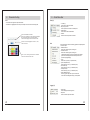
1.
Important Information
Please read this instruction manual carefully, and proceed with the installation ONLY
if you fully understand this manual. Make sure to pay attention to all the "Important!"
"Warning!" and "Caution!" messages through out the manual.
IMPORTANT!
• This product is legal for sale or use in California only on vehicles which may never
be driven on a public highway.
• This product is only for vehicles with 12V (battery) systems.
WARNING!
• Installation and use of this product should only be performed by a trained specialist,
who is very familiar with the automobile's mechanical, electrical, and fuel
management systems. If installed by untrained person, it may cause damage to the
unit as well as the vehicle.
• When using a soldering iron or other tools for installation, make sure you read and
understand the tool's user manual. Mis-use of these tools can cause serious injuries.
• Never tune the E-manage while the vehicle is moving.
• Never tune the e-Manage on public highways. This can be dangerous to you and
others on the road.
• When tuning and operating the vehicle in a garage, make sure that the garage is
equipped with a proper ventilation system.
• After installation and tuning, make sure to clean up every thing that would interfere
the driver. Wires, tools, and laptop computer may interfere with the driver and cause
accidents.
• Avoid open sparks, flames, or operation of electrical device near flammable
substances.
• Make sure there are no leaks in the fuel system and that all of the connections are
secure.
1
1.
Important Information
11.
Caution!
• Improper tuning of the e-Manage can cause damage to the engine.
• GReddy Performance Products, Inc. will not take any responsibility of damage
caused by improper installation or tuning.
• Tuning should be performed only by a technician who fully understand the vehicle’s
fuel management and ignition timing requirement for the engine being tuned.
• Always use a proper air/fuel ratio meter when tuning the e-Manage.
• Installation of this product requires modification of the vehicle’s electrical system.
• When making wire connections, be sure to remove the key from the ignition, and
disconnect the negative terminal of the battery.
• Never short out the system. It can damage the unit as well as the vehicle’s electrical
system.
• Read and fully understand the wiring diagram before making any wire connection.
• When connecting the connector, push it in all the way until you hear them click in
together.
About Maps and Setting
Analog Output Setting
• This map can be used to eliminate factory boost limiter on a vehicles with airflow meter that uses
pressure sensor to regulate boost limit.
• By intercepting the throttle signal wire, this feature can be used to output a different signal to
force the system to go in to “open loop”.
• This map can also be used to control the o2 sensor feed back or change the automatic
transmission shift schedule.
(How to set)
• Input the output signal to the corresponding input signal.
Voltage: V
Input range: 0~5V, 0.02V increment
Idle Adjustment Setting
• This map can be used to adjust the injector duty cycle during idle on vehicle with solenoid type
idle control valve.
(How to set)
• Monitor the idle control solenoid valve duty (AAC Duty) and the A/F ratio value at poor idling
condition in the data log feature.
• Input the injector increase rate to correct the poor idle in the monitored AAC Duty range.
• Input the activation throttle position value. Input “1%” to activate this feature only at throttle fully
closed, and “0” to deactivate.
IMPORTANT!
• The product and the instruction manual are subject to change without notice.
2
T.P value: %
Input range: 0~10%, 1% increment
Duty cycle : %
Input range: 0~100%, 0.5% increment
Adjustment rate: %
Input range: 0~30%, 0.5% increment
43
11.
About maps and Setting
2.
Auxiliary Output Setting
• This map can be used to control VTEC or for O2 Sensor Adapter (to control the O2 sensor feed
back feature to force the system to go in to “open loop”)
• In the “ON” area the system will output 12V signal. This is when the e-manage will send a signal
to activate the VTEC.
• Airflow adjustment can be made while in “ON” area. This will be the fuel compensation when the
Vtec shift points are changed.
Parts List
Please
•Please confirm that your recieve all the parts listed below. If there are anything
missing, please contact your Greddy Authorized Dealer.
(How to set)
• Click on the cells to turn “ON” and “OFF” in the corresponding load and rpm points.
• Input he airflow adjustment value.
RPM: rpm
Input range: 500~16000rpm, 50 rpm
Adj. value: %
Input range: -20~20%, 1% increment
Main Unit x1
CD-ROM x1
Allen Wrench x1
NVCS Setting
• This map is used to control the NVCS (Nissan Valve Control System)
• In the “ON” area the system will ground the connected signal channel.
(How to set)
• Click on the cells to turn “ON” and “OFF” in the corresponding load and rpm points.
RPM: rpm
Input range: 500~16000rpm, 50 rpm
Operation Manual
x1
42
Installation Manual
x1
Warranty Card x1
(Japan use only)
3
3.
Product Features
Each maps and settings
Airflow Adjustment
• Airflow Adjustment Map : This map is used to adjust the airflow sensor signal to the
ecu for fuel enrichment.
• Airflow Output Map : This map is used when eliminating the airflow meter to feed
airflow signal to the ECU by inputting the actual voltage or frequency in the map.
• Boost Limiter Cut Setting : This map is used to eliminate the factory boost limiter.
• Anti Engine Stall Setting : This map is used to prevent engine stall caused by blow
back to the airflow meter.
Injector Adjustment
• Injector Adjustment Map 1&2 : This map is used to adjust the injector signal to trim
and add fuel.
• Acceleration I/J Adjustment Map : This map is used to fine tune the fuel enrichment
during acceleration.
• Individual Cylinder I/J Adj. Map : This map is used to fine tune each cylinder.
• A/F Target Map :This map can automatically set the I/J Adj. Map to meet the inputted
Air/fuel ratio.
• Vehicle Speed Adj. Map : This map can be used to fine tune the fuel enrichment at
different speed.
• Water Temp Adj. Map : This map can be used to fine tune the fuel enrichment at
different coolant temp.
• Intake Temp Adj. Map : This map can be used to fine tune the fuel enrichment at
different Intake temp.
• Rev Limiter Cut Setting : This map can be used to change the factory rev limiter.
11.
About Maps and Setting
Individual Cylinder Injector Adjustment Map
• This map can adjust the ignition timing of each ignition channels.
• This map should be tuned only by a person who is experienced engine management tuner with a
proper testng equippments.
(How to set)
• Input the ignition timing adjustment value for each channel.
Adjustment value: º
Input range: -20~20º, 0.5º increment
Ignition Adjustment
• Ignition Adjustment Map 1&2: This map is used to adjust the ignition timing.
• Acceleration IGN Adj. Map : This map is used to fine tune the ignition timing during
acceleration.
• Individual Cylinder IGN Adj. Map : This map is used to fine tune each cylinder.
• Ignition Cut Setting : This feature is used to activate an ignition cut at desired rpm.
• A/T Shift Adj. Setting : This feature can be used to adjust the ignition timing to
prevent knock during shift up and shift down.
4
41
11.
About Maps and Setting
3.
Acceleration Ignition Adjustment Map
• This map is used to smooth out the ignition timing change during quick acceleration, by inputting
the ignition adjustment value, and the adjustment duration time.
• The feature will be activated when the unit detects a rapid throttle opening and be active for the
set adjustment duration time.
(How to set)
• Input the ignition timing adjustment value to the corresponding throttle rate and
rpm points.
• Input the adjustment decrease rate per rpm points. When this feature makes the inputted
igniton adjustment, it will take the inputted decrease rate to gradually return to normal setting.
Adjustment value: º
Input range: -20~20º, 0.5º increment
Product Features
Others
• Auxiliary Output Map : This map can be used to control VTEC, or O2 sensor adaptor
• NVCS Setting : This map can be used to control NVCS
• Analog Output Setting : This feature can be used to eleminate the boost limiter on a
vehicle with Airflow meter that uses a pressure sensor for boost limiter. This map also
can be used to alter the throttle position signal to force the system to open loop
condition.
• Idle Adjustment Setting : This feature can be used to impove the poor idle by
adjusting injector duty cycle at different idle control sonenoid valve duty.
• Speed Limiter Cut Setting : This feature can be used to eliminate the factory speed
limiter.
• Security Setting : The programed maps can be password protected.
4.
Before Installing the CD
Please read!
The e-manage Ultimate was desiged to be used with Windows 98SE, Me, 2000, XP.
Please use a PC that meets the system requirements listed below.
System requirements
• Pentium III 500MHz or higher
• Memory: 128MB (256MB recommended)
• Hard drive: at lease 20MB or moreavailable space
• Display: 1024x768 resolution 16-bit
• CD-ROM drive
• Interface: USB 1.1 or better
For information on setup and installation of new device for Windows, please refer to
the information that was included in the Windows software.
40
5
5.
Software Install / Driver Install
Software Installation Procedure
1. Turn the PC “ON”
2. Insert the CD-ROM in to CD-ROM drive. This Software will start the auto install.
Follow the on screen instruction.
3. When the installation is complete there will be a short cut on the
desktop. Click on this icon to start the program.
This installation will create a “TRUST” folder in the Progams File in C drive.
11.
About Maps and Setting
Ignition Adjustment Map 1 & 2
• This map is used to adjust the factory ignition timing.
• Input “0” for factory ignition timing.
• Input negative number to retard and positive number to advance the factory ignition timing.
(How to set)
• Input ignition timing adjustment value in the corresponding load and rpm points.
Adjustment value: º
Input range: -20~20º, 0.5º increment
Important
• If the auto install does not run automatically, manually install the software by
double clicking on the “setup.exe” file in the CD-ROM.
•If there are any problems with running the program or communication, please
uninstall the software and reinstall.
Software Uninstall Procedure
1. Open the “Contorl Panel” and click on “Add or Remove Program”.
2. Select “GReddy e-manage Ultimate” in the “Currently Installed Programs” and click
on “Change/Remove”
3. Follow the on screen instructions.
IMPORTANT
• The values inputted in thia map are not the actual ignition timing, they are adjustment values.
• When inputting adjustment values, make sure to monitor proper engine conditions.
Driver Install Procedure
• After the software is installed, and when the GReddy e-manage Ultimate is connected
to PC with a standard USB cable (available at any computer supply stores), the
system will automatically detect the e-Manage2 USB. Hardware Wizard will start the
installation procedure automatically. Follow the on screen instructions.
• The driver is installed at the time of the software install. Driver folder is located in
The GReddy e-manage Ultimate folder in TRUST folder located in Programs File.
C:¥Program Files¥TRUST¥GReddy e-manage Ultimate¥driver
6
39
11.
About Maps and Setting
Sub Injector Map
• This map is used to control the sub injectors.
• The input value can be set for injector duty cycle or duration.
• The sub injector channels must be configured in the “I/J” setting in the Parameter.
(How to set)
Input the sub injector duty cycle or duration to the corresponding load and rpm points.
6.
Operation Flow Chart
Please read!
Main Unit Jumper Setting
Refer to the Installation Manual
Harness Wiring
Refer to the Installation Manual
Check and confirm that the settings and wiring are correct.
IG ON (Start Engine)
If the ACTIVE LED does not light up
Checck the wiring.
(Main Unit Update)
If required
Duty cycle : %
Input range: 0~100%, 0.5% increment
Duration: ms
Input range: 0~20ms, 0.02ms increment
Parameter Setting
Setup the unit for the proper application
IG ON (Start Engine)
Check to see if ACTIVE LED is flashing errors
Start Tunning
38
7
7.
Connecting to Main Unit
Start the Application
1. Turn the IG key to “OFF” position, then connect the USB (A-B) cable to pc and
e-manage Ultimate.
2. Turn the IG key to “ON” position and double click on the
“e-manage Ultimate” sort cut. The following windows will
appear on the screen.
11.
About Maps and Setting
Rev Limiter Cut Setting
• This feature can be used to change the factory rev limit on engines that cuts fuel to regulate the
rev limit.
• Se the fuel cut activation throttle position value for the e-manage to recognize the throttle off
condition. When the e-manage Ultimate detect the throttle off condition, the fuel cut will activate
to prevent blowing flame out the tail pipe.
• This feature will not work on engines which cuts the ignition to regulate rev limit.
(How to set)
• Record the Injector duty cycle or duration, and rpm of when the fuel cut occurs.
• Input the rpm right before the fuel cut actually occurs in the “Hold” rpm.
• Input the new rev limit rpm to the “Limit” rpm.
• Input the injector duty cycle or duration for the corresponding load, “Hold” and “Limit” rpm points.
Make sure to monitor a reliable A/F meter to make this adjustment.
• Input the fuel cut activation throttle position value.
• Input the Hold Time to ensure factory rev cut hold.
Example: Factory rev limit is 7000rpm, new rev “Limit” is 9000rpm. “Hold” rpm will be 6800rpm.
Factory fuel cut signal last for 1.0ms, so the hold time needs to be over 10ms to ensure
the cut hold.
0
Factory Rev Limit
7000
New Rev Limit
9000
10,000
rpm
Hold rpm
6800
Please
Hold Time
1.5ms
T.P value: %
Input range: 0~10%, 1% increment
Hold Time: ms
Input range: 0~5.0ms, 0.1ms increment
RPM: rpm
Input range: 5000~10000rpm, 50 rpm
Duty cycle : %
Input range: 0~100%, 0.5% increment
Duration: ms
Input range: 0~20ms, 0.02ms increment
• Please make sure to use USB1.1 compatible cable.
8
37
11.
7.
About the Maps and Setting
Vehicle Speed Adjustment Map
• This map is used for vehicle speed fuel compensation.
(How to set)
• Input the injector duty cycle or duration value for the corresponding vehicle speed and rpm
points.
Connecting to Main Unit
Main Unit Update
1. When the e-manage Ultimate is connected to PC, and if there are newer version
of firmware on the PC, the system will automatically check the unit and show the
window shown below. Click “OK” to update.
Vehicle Speed: km/h
Input range: 0~400km/h, 10 increment
*If the e-manage Ultimate is programmed with the same version as the PC, this will
not appear.
Water Temp Adjustment Map
• This map is used for water (coolant) temp fuel compensation.
2. Select the update file “gsc02.p” and the system will automatically update the unit.
Download will take approximately 1 minute.
(How to set)
• Input the injector duty or duration value for the corresponding water temp and rpm points.
Temp: ºC
Input range: -20~120ºC, 1º increment
Adjustment Value: %
Input range:-20~20%, 0.5% increment
Adjustment Duration: ms
Input range: -4~4ms, 0.02ms increment
Intake Temp Adjustment Map
• This map is used for intake air temp fuel compensation.
(How to set)
• Input the injector duty or duration value for the corresponding intake air temp and rpm points.
Temp: ºC
Input range: -20~120ºC, 1º increment
Adjustment Value: %
Input range:-20~20%, 0.5% increment
Adjustment Duration: ms
Input range: -4~4ms, 0.02ms increment
36
Please
• While communicating, please do not turn of the igntion “OFF” or disconnect the
USB cable. This can damage the unit and will cause irratic operation.
9
7.
Connecting to Main Unit
3. After the update is complete, message shown below will appear. Click on “OK” and
turn the ignition key “OFF”, and wait couple seconds before turning back “ON”.
11.
About Maps and Setting
A/F Target Map
• This map is used to automatically program the selected map (in the “A/F Taget” section in the
parameter) with the inputed A/F values.
• This feature will monitor the A/F sensor that is connected to the “OPTION” port and confiured in
the “”Front Panel” and make the proper adjustment to the selected map to achieve the inputed
air/fuel ratio.
(How to set)
• Input the A/F target value for the corresponding load and rpm points.
4. Confirm the update in the version information window in the “HELP(H)” pull down
menu. If the F/W version matches with the update file update is complete.
* Be sure to input “-” in the area where factory ecu is in the closed loop (ecu monitoring and
correcting by monitoring the factory O2 sensor signal).
* While the ecu is in closed loop, ecu will continuously adjust the ari/fuel ratio between 14~15.
During this time, A/F Target map feature will not function propelly since the ecu is making
adjustments.
* To force the ecu to go in to Open Loop, “Auxiliary Output Map” can be used.
To manually update
For any reason, if the update failed, update the unit manually by selecting “Main Unit
Update” in the “Communication” pull down menu.
A/F
Input range: 10~18, 0.1 increment.
* The update file “gsc02.p” is located in the “e-manage Ultimate” folder which is
located in the “TRUST” folder in the “Programs Folder”. When downloading new
updates, make sure that the “gsc02.p” file is in the “e-manage Ultimate” folder.
If the latest update files are not in this folder, the system cannot check the newest
version information, and auto update cannot be performed.
IMPORTANT
• To use A/F Target Map, A/F ratio meter will an external output signal channel is required
CAUTON
• If A/F Target feature is activated in the area where the facotory ecu is in the closed loop, the
A/F Target map will input inproper values to the selected map.
10
35
11.
About Maps and Setting
Individual Cylinder Injector Adjustment Map
• This map can adjust the injector duty cycle or duration of each injector channels.
• This map should be tuned only by monitoring each individual cyclinders a/f ratio.
(How to set)
• Input the Injecctor duty cycle or duration adjustment value for each channel.
8.
Please Setup
Parameter Setting
Parameter Setting
• By selecting the vehicle’s engine code, the system will set up other setting in the
parameter tabs for the specific application, and will make it possible to start the engine.
• If any of the sensors are changed, necessary parameters is required to be adjusted.
Follow the instructions for the appropriate parameter tabs.
• If any features were added or removed, necessary parameters is required to be
adjusted. Follow the instructions for the appropriate parameter tabs.
Open the “Parameter Setting” window by clicking the parameter icon shown below.
Adjustment rate: %
Input range: -10 ~ 10%, 0.5% increment
Adjustment duration: ms
Input range: -2 ~ 2ms, 0.02ms increment
34
Parameter Icon
11
8.
Parameter Setting
Please Setup
Vehicle Type
• This section is used to setup the e-manage Ultimate for the application it is being used on.
• By Selecting the Engine Code, the system will automatically set the sensor types, but when some
of the sensors are changed or upgraded, this feature can be used to make any necessary
changes.
Select the engine type
Number of cylinders can be changed for different
application.
11.
About Maps and Setting
Injector Adjustment Map 1 & 2
• This map is used to add or trim the factory injector fuel injection by altering the factory injector
signal.
• The “0” within the maps are factory ecu setting (no adjustment made).
• By configuring the injector input channels and making the proper wiring and jumper setting, this
Map can be used to “Add & Trim” or “Add” only.
(How to set)
• Input the Injector duty cycle or duration adjustment value to the corresponding load and rpm
points.
Displacement can be changed for different application
Shows the engine’s airflow metering type.
Shows the airflow spec
Used when changing the airflow meter. Select the
new airflow meter type.
Adjustment rate: %
Input range: -80~100, 0.5% increment
Adjustment Duration: ms
Input range: -20~20ms, 0.02 increment
Select how the rpm signal will be monitored.
* Most of the applications will be from RPM signal
(ECU Tach signal)
This is automatically set when the engine type
is selected.
This is used to correct any differences in the displayed
ignition timing and the actual timing.
*Example: If the actual ignition timing is 15º and the
data log display 13º enter “2” to offset the
value.
Vehicle Speed Pulse value will display.
Used to correct the vehicle speed signal from
different tire size or final gear.
This feature is used to eliminate the factory speed limiter.
• This feature will not work on vehicles without vehicle speed signal.
• This feature may not work on some vehicles.
12
Acceleration Injector Adjustment Map
• This map is used to smooth out the fuel enrichment during quick acceleration, by inputting the
injector duty cycle or duration adjustment value, and the adjustment duration time.
• This feature will be activated when the unit detects a rapid throttle opening and be active for the
set adjustment duration time.
(How to set)
• Input the Injector duty cycle or duration adjustment value to the corresponding throttle rate and
rpm points.
• Input the adjustment decrease rate per rpm points. When this feature makes the inputted
adjustment, it take the inputted decrease time to gradually return to normal setting.
Adjustment rate: %
Input range: -80~100, 0.5% increment
Adjustment Duration: ms
Input range: -20~20ms, 0.02 increment
Decrease rate: ms
Input range: 0.5~20ms, 0.5 increment
33
11.
About Map and Setting
Anti Engine Stall Setting
• This feature is used to prevent engine stall caused by turbo blow back to the airflow meter.
• Input the Throttle Position point which will activate this feature for the set amount of time. When
the throttle position is below the inputted point, the e-manage Ultimate will recognize the
accelerator as closed and will clamp the airflow meter signal going back to ECU.
(How to set)
• Input the airflow meter signal clamp voltage (or frequency) in each rpm range.
• Input the throttle position activation value. This feature will activate when the unit detect the
throttle position below the set value.
• Input the activation duration time. This is the time it will take for this feature to turn off and go
back to normal setting.
* If the throttle value is set to 1%, this feature will only activate only when the throttle is completely
closed.
* If the throttle value is set to 0%, this feature will not activate.
* If the time value is set to 0 “-.-” will be displayed, and this feature will be active while the throttle
and rpm conditions are met.
Throttle Position: %
Input range: 0 ~ 10%, 1% increment
Time: s
Input range: 0 ~ 5sec, 0.2sec increment
RPM: rpm
Input range: 500 ~ 16000rpm, 50rpm increment
Clamp Value: v or Hz (automatically set depending on the equipped sensor)
Input range: 0 ~5v, 0.02v increment (hot wire, flap type airflow meter, or pressure)
Input range: 0 ~ 3150Hz, 2Hz increment (Karman Vortex type airflow meter)
8.
Parameter Setting
Throttle
• This section is used to set the minimum and maximum voltage of the TPS signal.
(How to set)
Turn the ignition key to “ON” position (without engine running)and fully depress the accelerator to set the MIN
and MAX voltage. The system will automatically detect the minimum and maximum voltage and will set the
0~100% throttle range. This can also be done while the engine is runing to comfirm setting.
Normal Type - Voltage increases as the
accelerator is depressed.
Reverse Type - Voltage decreases as the
accelerator is depressed.
This window will display the current voltage and
the throttle position 0~100%
Manual Setting
Place a check mark on these boxes to manually set
the throttle setting. This will disable the auto detect.
Input the desidered voltages for “MIN” and “MAX”
(Input range) 0.00~5.00V, 0.01 increment
Voltage at fully closed will display.
* MIN will the the voltage that was automatically detected.
Voltage at fully opened will display.
* MAX will the the voltage that was automatically detected.
IMPORTANT
• When setting the throttle while the engine is running, be sure not to over rev the engine
• This setting will not program on a vehicle that does not have a throttle position signal, or
vehicle with minimum and maximum switch only.
32
13
8.
Parameter Setting
11.
CH Setting
• This section is used to configure the optional channels for “Water Temp/Knock Signal”,
“Intake Temp/Knock signal”, “Airflow Meter 2/VTEC Output”, “Analog Input and “Analog Output”.
• The optional channels are Pin # 14,31,32, 37, and 38 on the e-manage Ultimate harness.
See the Harness Diagram in the Installation Manual. Depending on what these pins are
connected to, these channels must be activated in this window.
Pin # 32 and 38 in Connector C are configured in these
sections.
• When connecting Water temp and/or Intake temp
sensor, place a check mark in the box and select the
sensor Type.
• The Unit can also use these temp sensor signal to
activate a relay for a device. Enter the relay
conditions to activate a device.
• Output signal wire can be activated in the I/J channel
setting.
• Input range: 0º ~200º, 1º increment
About Maps and Setting
Boost Limiter Cut Setting
• This feature can eliminate the factory boost limiter by clamping the airflow meter, or pressure
sensor output signal to the ecu at the value right before ecu recognizes as the limit. Since the
ecu would not recognize the amount of increase in airflow above the clamped value, it is
neccesary to make proper fuel compensation in the I/J map.
* For the vehicles equipped with airflow meter which uses a pressure sensor to activate
the boost limiter, such as ER34, FC3S, and most Subaru, this feature will not eliminate the boost
cut. Use the “Analog Output Setting” to eliminate the factory boost cut.
(How to set)
• Monitor the airflow meter signal and rpm of when the boost cut occurs in the data log feature.
Input the airflow meter clamp value right before the cut occurs in each rpm points.
To monitor knock sensor signal in the Real Time Display,
set this section and select the sensor type.
• Input the frequency of the knock sensor when using
the non-resonant type sensor.
This section will configure the Pin # 14 in Connector B.
• When the Engine type is selected, this section will be
set automatically. If the input signal is changed make
the necessary setting.
• Pin# 14 can be used for Second Airflow meter, or for
auxiliary output signal for Auxiliary Map to control
VTEC or relays. (Can be used for O2 sensor adaptor)
RPM: rpm
Input range: 500 ~ 16000rpm, 50rpm increment
Clamp Value: v or Hz (automatically set depending on the equipped sensor)
Input range: 0 ~5v, 0.02v increment (hot wire, flap type airflow meter, or pressure)
Input range: 0 ~ 3150Hz, 2Hz increment (Karman Vortex type airflow meter)
These sections will configure the Pin # 31, and 37 to be
used for the “Analog Output Setting”. Select the type of
signal that is inputted and outputted.
IMPORTANT
• If Water and Intake Temp are selected Knock 1 & 2 cannot be used.
14
CAUTION
• When the airflow signal is clamped, ecu would not recognize the amount of increase in airflow
above the clamped value, it is neccesary to make proper fuel compensation in the I/J map.
31
11.
About Maps and Setting
8.
Airflow Adjustment Map
• The signal from the Airflow meter (or pressure sensor, Karman vortex sensor) calculates the
amount of intake airflow. The values inputted in this map alters the output signal going to the ecu.
• When a positive numbers are inputted, e-manage Ultimate sends a signal to the ecu telling there
are more airflow than it actually are. Making the ecu inject more fuel and advance the ignition
timing. (Since ecu thinks there are more airflow, it reads higher part of the fuel and ignition map)
• When a negative numbers are inputted, e-manage Ultimate sends a signal to the ecu telling there
are less airflow than it actually are. Making the ecu inject less fuel and retarding the ignition
timing. (since ecu thinks there are less airflow, it reads lower part of the fuel and ignition map)
(How to set)
• Input adjustment value to the corresponding load and rpm points.
Adjustment value: %
Input range: -100~100%, 0.5 increment
Parameter Setting
Front Pannel
This section is used to configure the “DIP SWITCH”, “OPTION 1&2”, SWITCH, SERIAL, on the
front pannel of the e-manage Ultimate unit.
Select the sensor type or switches that are connected to the
OPTION 1&2 port from the pull down menu.
Pull down menu items
GReddy Pressure Sensor • • • • This sensor signal can be used as the load value for the map instead of factory
sensor. (Used if the application exceeds the capacity of the factory sensor)
GReddy Temp Sensor • • • • • • This sensor can be used to monitor water, intake, and/or oil temp.
A/F Sensor • • • • • • • • • • • • • • This Sensor can be used for the Target Map and to monitor the air/fuel ratio in the
Data Log feature.
Multi Switching System • • • • • By linking the e-manage Ultimate to Multi Switching System, the e-manage can
adjust the ignition timing when the Multi Switching System activates the optional
output.
External Switch • • • • • • • • • • • Switch can be used to start and stop the data logger or for ignition cut for launch
control.
Factory Pressure Sensor • • • • By selecting the sensor type, pressure can be monitored in the data log feature.
Select the GReddy Warnning Meter that is connected to
the serial port to monitor in the data log feature.
Airflow Output Map
• This map is used when the factory airflow meter is removed. By using a pressure sensor or
throttle sensor signal, input the airflow signal which would be sent to ecu at each rpm points.
This map will provide the ecu the airflow meter signal it requires.
(How to set)
• Input the Airflow output value to the corresponding load and rpm points.
Adjustment value: V, Hz
Input range: 0~5V, 0.02V increment
Input range: 0~3150HZ, 2Hz increment
IMPORTANT
The Active LED can be used as a warning light by setting
the rpm and by selecting the desired input value.
“and”: Both RPM and the selected input condition must
meet the set conditions for the warning to come on.
“or” : Either rpm or the selected input conditon must meet
meet the set conditions for the warning to come on.
RPM
Input range: 0~16000rpm, 1 rpm increment
Input signals
Select from the input signal menu to activate the
warning feature.
The dip switches on the front pannel can be configured in
this section. 2 different Injector Adjustment Map and
Ignition adjustment map can be programmed and selected
by this switch. Primary and secondary injectors as well as
leading and trailing ignition can be separated in these 4
settings on ratary engines.
Setup each of the dip switches from the pull down menu.
• Airflow Adjustment Map and Airflow Output Map can not be used at the same time.
30
15
8.
Parameter Setting
11.
A/F Target
• This section is used to setup the system for the “A/F Taget Map”.
Select the map that A/F Target Map would program.
About Maps and Setting
About Map Scale
• The scale can be changed in each of the maps.
(How to set)
• Click on the “Change Scale” button to release the lock.
* Once it is unlocked, the blue highlighted area will be clear, and will be adjustable by “Page up”,
“page down” key or manually inputting a value.
Set the Water Temp condition of when the feedback
would be activated.
Input range: 30~110Cº
Set the Throttle Position condition of when the feedback
would be activated.
Input range: 0~100%
Set the warm up time of the installed A/F sensor. During
this time, the A/F feedback will not function.
*Please check with the installed A/F sensor manual for
proper warm up time.
Input range: 0~600sec
Input the feedback correction cycle time.
shorter the time the faster it will reach the target, but if it
is too fast, the correction will be inconsistant.
Input range: 20~300ms
Input the feedback correction value per cycle.
Higher the value, faster it will reach the target, but if the
value is too high, the correction will be inconsistant.
Input range: 0.5~5%
• The “0” within the maps are represented as factory ecu setting (no adjustment made).
RPM: rpm
Input range: 0 ~ 16000rpm, 50rpm increment
Load columns: V, Hz, Absolute pressure value (kPa, kg/cm2, mmHg, PSI)
Relative pressure value (kPa, kg/cm2, mmHg, PSI)
The Load value is automatically set when the airflow meter type is selected in the “Vehicle”
setting. When the unit is changed in the “Unit” menu, the value will be set to it’s closest value.
Input range: 0 ~ 5v, 0.02v increment (hot wire, flap type airflow meter, or pressure : V)
Input range: 0 ~ 3150Hz, 2Hz increment (Karman Vortex type airflow meter : Hz)
Input range: 0 ~5v, 0.02v increment (GReddy pressure pressure sensor : V)
16
29
11.
About Maps and Setting
8.
About Map Tree
•Map Tree will display the activated maps in the window.
Button to activate the window tabs.
Tab turned on.
Parameter Setting
I/J
• This section is used to configure individual injector output channels.
• The open injector channels can be used for sub injectors, NVCS, or activate relays.
* When the engine type is selected in the “Vehicle” section, the number of injector channels used
and injector size will automatically set.
Configuring Main Injectors
Click to change
Set the number of Injector channels being used for
main indicators.
* # of output can be changed to convert group
injection to sequential injection
Activate the I/J output channels for the I/J Adj. Map
they are used for. I/J output CH are used if adding
and trimming (+/-) fuel in the map.
Tab turned off.
Set to “+ / -” to trim and add fuel in the I/J Adj map
and “+ only” for add only. Default setting is “+/-”.
Select the cell and right click to display the menu,
left click to select.
This section is used to configure the upgraded
injectors. Input the upgraded injector size and it’s
Lag Time.
* Make sure to use the same type of injectors as
factory injectors. (Same resistance)
* Primary and secondary injectors can be configured
separately for rotary engines.
Popup Menu
Right click to open the popup menu at any time.
Copy
Paste
Cut
Interpolate-4corner
Interpolate-Row
Interpolate-Corner
Map Tree
Map Trace
Changing Injector Channels
Vehicles with simultaneous and grouped injection that has cam and crank angle signal can be
changed to sequential injection by configuring the input and output signal.
To change the injector channels, set the output channel number, activate the each channel and
set the injection timing.
Select the number of output channels used.
Set the injection timing of the added channels from
the menu.
(select the cell and right click to view menu)
Reference
signal
Altered
timing
This shows retarding 180º of the CH1 signal
for CH4.
28
17
8.
10.
Parameter Setting
When using these channels for other features.
• The open Injector channels can be used for NVCS, or to activate relays for Water temp, Intake
temp, and/or warning.
Configure the channels by selecting the item from
the menu. Select the cell and right click to view the
menu, and left click to select.
About Tool Bar
Tool Bar Description
1
2
3
4
5
6
7
8
9
10 11
12
13 14 15 16 17
IMPORTANT
• When using the channels to activate relays, “Front Panel” and “CH Setting” must be
configured.
• When using the channels to control NVCS, make sure that the channel wires are connected.
• Sub Injectors
When sub injector feature is selected, the “RPM” will be automatically selected as a reference
signal type.
When using same number of sub injector as main injectors, they can be synchronized with the
factory injection order.
RPM: Sub injectors will inject once every 2 rpm pulse signal.
On 4 cylinder, they will inject twice every 2 rev. and
3 times on 6 cylinder.
CH-#: Sub injectors will inject at the same time as the
selected channel.
* Right click to view this menu, and left click to select.
18
Menu
1. New File (Ctrl+N)
2. Open (Ctrl+O)
3. Save (Ctrl+S)
4. Print (Ctrl+P)
Edit
5. Cut (Ctrl+X)
6. Copy (Ctrl+C)
7. Paste (Ctrl+V)
8. Undo (Ctrl+Z)
9. Redo (Ctrl+Y)
10. Interpolate
Setting
11. Map Tree (Ctrl+A)
12. Parameter Setting
Option
13. Map Trace setting (Ctrl+M)
14. Data Logger (Ctrl+T)
Communication
15. Import Data (Ctrl+R)
16. Compare Data
17. Export Data (Ctrl+W)
27
9.
Parameter Setting
8.
Communication
Parameter Setting
Ignition
Channel Configuration
• When the engine type is selected in the “Vehicle” setting the number of the ignition input and
output channels is automatically set.
• In this section each ignition input and output channels can be configured.
• Disrtibuter and group ignition type engines can be converted to individual ignition system by using
cam and crank angle signals with neccesary ignition system modifications and wiring.
Make the neccesary changes by selecting the number of input and output CH
numbers.
• Real Time Communication
Select to communicate with e-manage Ultimate at real time.
• Import Data (R) Ctrl+R
To import data from e-manage Ultimate on to the desk top.
• Compare Data
To compare the data in the e-manage Ultimate with the data on the desk top.
• Export Data (W) Ctrl+W
To export data to e-manage Ultimate from desk top.
• Main Unit Update
To update the E-manage Ultimate main unit.
Activate the IGN output channels for the IGN Adj. Map they are used for.
Right click to view the menu and left click to select.
Ignition Cut Feature
• This section can be used to configure the ignition cut feature to set a rev limiter at verious
conditions. (This feature will not eliminate the factory rev limiter. See Rev Limiter Cut Setting)
• Set the “Start” rpm for launch control. When there are no vehicle speed signal and throttle is open
above the set %, the ignition cut will be activated.
• “IGN cut rpm” sets the max rev limit, and “Shift Up” will prevent over rev while power shifting
using a switch.
Input the start rev cut rpm. This will only activate only when
e-manage does not detect vehicle speed signal and throttle
position is above set value in “Throttle Position”.
Input range: 0~9999rpm 1 rpm increment
Help (H)
• Version Information
To check the current software and main unit version type.
Input the max rev limit rpm. This will not eleminate the
factory rev cut. Input range: 0~9999rpm 1 rpm increment
Input the rpm limit while shifting up. (power shifting)
Input range: 0~9999rpm 1 rpm increment
Software version type.
e-manage Ultimate main unit firmware version.
e-manage Ultimate main unit update file version.
Communication Status Indicator
The e-manage mark indicator in the top right corner will show the current online status.
OFF LIN
ON LINE
ON LINE Communicating at real time
ON LINE Recording Data
26
Steady Yellow
Steady Green
Flashing Green
Steady Red
Select the switch used to activate the “Shift Up” ign. cut.
The switch must be configured in the “Front Panel” and
connected to the Option 1 or 2 Port. Switch can be cluch
switch or shift up switch on a sequential transmision.
Ignition cut will activate when throttle position exceed
above the input throttle position % value.
Input range: 50~100%, 1% increment
Ignition timing can be adjusted while the ignition
cut is activated. Place a check mark in the boxes and input
the adjustment value.
Input the number of vehicle speed signal pulse it take to
detect vehicle movement and to cancel the start rev cut to
normal max rev limit.
IMPORTANT
• make to set the “Shift Up” rpm value is lower than “IGN cut rpm”.
19
8.
9.
Parameter Setting
Trace
• This section will configure the map trace features.
• This feature can highlight the cells in the opened maps to show the current cells being read.
About Menu Bar
View (V)
• Tool Bar (T)
Click to show or hide the Tool Bar.
• Map Tree (A) Ctrl+A
Click or press Ctrl-A to show or hide Map Tree.
• Status Bar (S)
Click to show or hide the Status Bar.
• Window
Select to view the maps tiled or cascade.
There are two selectable cursor sizes.
When 4 cursor is selected, the current location will highlight in
the color selected in “MAIN”. The cells that made the
correction will be highlight in the color selected in “SUB”.
The trace can be set to highlight the cells for 1 sec, 3 sec,
10sec or continuous.
Unit
Color 1 , Color 2, and Log Trace color can be customized.
Click on the cell to view the color chart.
Select the desired units for the following signals for be displayed and
used in the maps.
• Relative Pressure
Select from x100kPa, kg/cm2, mmHg, PSI
• Absolute Pressure
Select from x100kPa, kg/cm2, mmHg, PSI
If the Relative Pressure Conversion is selected, the absolute
pressure will be displayed like the relative pressure value.
(like a boost gauge display)
• Temp
Select from ºC (Celsius) or ºF (Fahrenheit)
• Injector Adjustment map
Select from Duty cycle (%), or Duration (msec)
• Rev Limiter map
Select from Duty cycle (%), or Duration (msec)
• Sub Injector map
Select from Duty cycle (%), or Duration (msec)
• Ignition Adjustment map
Currently, ignition adj. value only can be selected.
In the future the actual ignition timing can be inputted.
Logger (O)
• Data Logger
Select to display the data log feature.
• Map Trace
Select to start the map trace feature.
20
25
9.
About Menu Bar
8.
Parameter Setting
Map Select
• This section is used to activate the desired features and to set the password to lock them.
• Place check marks on the features to activate.
File (F)
Edit (E)
• Interpolate-4corners
Select and highlight few cell in the map and select
“Interpolate-4corners” to interpolate between 4 corners.
• Interpolate-Rows
Select and highlight few cells in the map and select
“Interpolate-Rows” to interpolate horizontally.
• Interpolate-Columns
Select and highlight few cells in the map and select
“Interpolate-Columns” to interpolate vertically.
Security Setting
• Each maps can be locked to prevent unwanted tampering.
• The settings can also be pass word protected.
(How to set)
To Lock • • • Click on the green unlocked icon. Icon will turn to red (locked icon).
To Unlock • • Click on the red locked icon. Icon will turn to green (unlocked icon).
Unlocked
Locked
The maps can be changed while unlock.
The maps cannot be changed while locked
Password Protect
Input password
confirm password
24
21
8.
8.
Parameter Setting
Main Logger
• The e-manage Ultimate unit has a built in data logging features that can record up to 8 different
input signals up to 1000 minutes without having PC connected.
• This section is used to configure the main unit data logger feature.
• This feature can be activated by the Remote Switching System or external switch connected to
Option 1 or 2 in the front panel. The Option port must be configured in the “Front Panel” setting
for the switch to work.
Select the sampling cycle from pull down menu.
20,50,100,200,500, or 1000ms
Maximum record time will display. Time will vary
depending on the recording cycle.
10~500 minutes
Select the switch used to activate the main unit logger
Select the data to record from the menu.
Click on the icon to view the menu.
Sampling Cycle / Recording Time
22
Parameter Setting
A/T Shift
• This section is used to prevent knock during shift up and down on automatic trasnsmission
equipped vehicle by adjusting the ignition timing.
• This feature also can be used to minimize shock during shifting up and down.
Input the rpm condition to activate this feature.
Input Range: 0 ~ 8000rpm, 50rpm increment
Input the Throttle condition to activate this
feature.
Input Range: 0 ~ 100%, 1% increment
Input the rpm value per 50ms to detect the shift
change. e-manage will detect the rpm change
due to shift up or down. This setting will set the
sensitivity of the detection.
Input Range: 10 ~ 500rpm, 10rpm increment
Input the return time of the adjustment back to
0. The adjustment will retun to normal after the
inputted time.
Input Range: 0 ~ 50msec, 1msec increment
Input the ignition adjustment amount for shift
up and shift down. When the above set
conditions are met, this feature will adjust the
ignition timing for the set amount of time.
Input Range: 0 ~ 20º, 1º increment
23