1
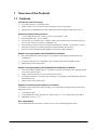
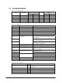
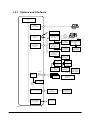
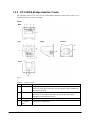
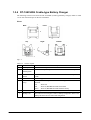
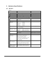
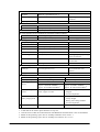
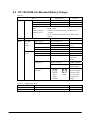
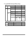
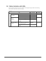
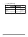
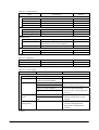
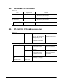
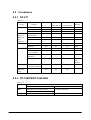
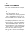
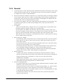
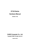
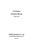
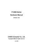
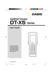
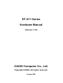
DT-X11 Series
Hardware Manual
(Version 1.01)
CASIO Computer Co., Ltd.
Copyright ©2006. All rights reserved.
August 2006
Table of Contents
Chapter 1.
1.1.
1.2.
1.2.1.
1.3.
1.3.1.
1.3.2.
1.3.3.
1.3.4.
1.3.5.
Chapter 2.
2.1.
2.2.
2.3.
2.4.
2.5.
2.6.
2.7.
2.8.
2.9.
Chapter 3.
3.1.
Chapter 4.
Chapter 5.
5.1.
5.1.1.
5.1.2.
5.1.3.
5.1.4.
5.1.5.
5.1.6.
5.2.
5.2.1.
5.2.2.
5.2.3.
5.2.4.
5.2.5.
5.2.6.
5.3.
5.3.1.
5.3.2.
5.3.3.
Editorial Record
Preface
Overview of the Products
Features
Available Models
Options and Interfaces
General Guide
DT-X11
DT-167CHGE Car Mounted Battery Charger
DT-160IOE Bridge Satellite Cradle
DT-169CHGE Cradle-type Battery Charger
DT-5022CHG Dual Battery Charger
Hardware Specifications
DT-X11
DT-160IOE Bridge Satellite Cradle
DT-167CHGE Car Mounted Battery Charger
DT-169CHGE Cradle-type Battery Charger
DIP Switch Setting for DT-160IOE
Status Indication with LEDs
DT-5022CHG Dual Battery Charger
HA-A20BAT/DT-5025LBAT
DT-894CFU CF Card Extension Unit
Interfaces
DT-X11
Product Identification and Reference Numbers
Quality References
Environmental Performances
DT-X11
DT-160IOE/DT-169CHGE
DT-167CHGE
DT-5022CHG
HA-A20BAT/DT-5025LBAT
DT-894CFU
Electrical Performances
DT-X11
DT-160IOE/DT-169CHGE
DT-167CHGE
DT-5022CHG
HA-A20BAT/DT-5025LBAT
DT-894CFU CF Card Extension Unit
Mechanical Performances
DT-X11
DT-160IOE/DT-169CHGE
DT-5022CHG
2
4
5
6
6
8
9
10
10
12
13
15
16
17
17
20
22
23
24
25
26
29
30
31
31
34
35
35
35
35
36
36
37
38
39
39
39
39
40
40
40
41
41
41
41
5.3.4.
5.3.5.
5.4.
5.4.1.
5.4.2.
5.4.3.
5.5.
5.5.1.
5.5.2.
Chapter 6.
6.1.
6.2.
Chapter 7.
7.1.
7.2.
7.2.1.
7.2.2.
HA-A20BAT/DT-5025LBAT
DT-894CFU CF Card Extension Unit
Reliability
DT-X11
DT-160IOE/DT-169CHGE
DT-5022CHG
Compliance
DT-X11
DT-160IOE/DT-169CHGE
Cable Specifications
For Chain Connection and Short Length
For Chain Connection and Long Length
Precautions
Handling
Safety
Battery Pack/Memory Backup Battery
General
42
42
43
43
43
44
45
45
45
46
46
47
48
48
49
49
51
No part of this document may be produced or transmitted in any form or by any means, electronic or
mechanical, for any purpose, without the express written permission of CASIO Computer Co., Ltd.
in Tokyo Japan. Information in this document is subject to change without advance notice. CASIO
Computer Co., Ltd. makes no representations or warranties with respect to the contents or use of this
manual and specifically disclaims any express or implied warranties of merchantability or fitness for
any particular purpose.
© 2006 CASIO Computer Co., Ltd. All rights reserved.
3
Editorial Record
Manual
Version no.
0.90
1.00
1.01
Date edited
February 2006
March 2006
August
Page
8
26
Content
Tentative version
Original version
The content in Table 1.2 of Chapter 1.2 is corrected.
The content in Table 2.9 of Chapter 2.7 is corrected.
4
Preface
This reference manual describes about the CASIO DT-X11 series handheld terminals with C-MOS
imager or Laser Scanner integrated.
A new generation of handheld terminal has been developed. CASIO introduces the revolutionary
DT-X11 series of handheld terminal with built-in Intel® PXA255 Application Processor, C-MOS
imager or 1D bar code scan engine and diverse wireless LAN communications via Bluetooth,
IEEE802.11b WLAN and WAN card.
Running under Microsoft® Windows® CE 5.0 operating system, the rugged DT-X11 is designed
specifically with the transportation/delivery and logistics in mind.
In this reference manual, the DT-X11 series is described as “DT-X11” or “the terminal” or
“handheld terminal”.
5
1. Overview of the Products
1.1 Features
Incorporates .NET technology
• Uses WindowsCE 5.0 operating system.
• Makes effective use of .NET resources developed by other corporations.
• Employment of eMbedded OS makes it possible to build a flexible WindowsCE system.
Enhanced communicating functions
• Covers GPRS/WLAN, etc. by using various communication cards.
• Built with Bluetooth® Ver1.2 module.
• The transfer rate of the WLAN is 5 Mbps, which is the maximum rate of communication for
peer-to-peer connection with PC via IEEE802.11b.
• The following protocol stacks are available for Bluetooth® interface: GAP (Generic Access),
SDP (Service Discovery), SPS (Serial Port), Dialup Network, File Transfer.
• Security function (PEAP EAP-MS-CHAP V2, EAP-TLS, MD5+WEP128)
Superb scanning capability (DT-X11M10E/DT-X11M10RC)
• With the installed bar code scan engine it is possible to read industrial standard bar code
symbologies.
• Scanning performance is comparable to the CASIO IT-500 series handheld terminal.
• Multi-step bar code read function.
Superb scanning capability (DT-X11M30E/DT-X11M30U/DT-X11M30RC)
• With the installed C-MOS imager it is possible to read 2D symbologies/1D symbologies/OCR
fonts and to capture images.
• Image capturing function (2 to 256 monochromatic tones).
• Scanning performance on 1D bar code symbology is comparable to the CASIO DT-800 series
handheld terminal.
• Multi-step bar code read function.
Support of outstanding development environment
Ample Microsoft development tools provided for easy application development and an advanced
debug environment.
• Visual Studio 2005
• Visual Studio.NET 2003 (WindowsCE .NET Utilities v 1.1 for Visual Studio .NET 2003)
• eMbedded Visual C++ 4.0
High expandability
The standard PCMCIA slot makes it possible to use various standard peripheral cards.
6
Aiming to a full compliance with the “Restriction of the use of certain Hazardous
Substances in electronic equipment (RoHS)” set mandatory on July 1 2006
The following products have been assembled with devices, components and parts manufactured
using Lead (Pb) free solder.
DT-X11M10E
DT-X11M10RC
DT-X11M30E
DT-X11M30U
DT-X11M30RC
7
1.2 Available Models
Table 1.1
List of models
Model
Scan Engine
DT-X11M10E
DT-X11M10RC
DT-X11M30E
DT-X11M30U
DT-X11M30RC
Laser Scanner
Laser Scanner
C-MOS Imager
C-MOS Imager
C-MOS Imager
Table 1.2
Wireless Communication
Bluetooth IEE802.11b
Yes
Yes
Yes
No
Yes
Yes
Yes
Yes
Yes
No
Memory
RAM
FROM
64MB
128MB
64MB
128MB
64MB
128MB
64MB
128MB
64MB
128MB
Options
Model
DT-160IOE
DT-169CHGE
DT-891WH
DT-167CHGE
DT-827CAC
DT-5022CHG
AD-S45150AU
Product
Bridge Satellite Cradle
Cradle-type battery charger
Wall-mount Unit
Car Mounted Battery Charger
Car Power Cable
Dual battery charger
AC adaptor
Remark
Not marketable in the USA/Canada
AC input 100 to 230VAC. With US power cord. For
DT-5022CHG
AC input 100 to 230VAC. With European power
cord. For DT-5022CHG
AC input 100 to 230VAC. For
DT-160IOE/DT-169CHGE
Lithium-ion rechargeable battery 1,700 mAh
Lithium-ion rechargeable battery 3,400 mAh
CF Type I/ Type II. The large-size card cover
comes as standard
For standard-size card
For large-size card
25-pin male
25-pin female
Length; 1.5 m, 9-pin female
Length; 1.0 m
Length; 2.0 m
AD-S45150AE
AD-S42120AE
HA-A20BAT
DT-5025LBAT
DT-894CFU
Battery pack (Standard)
Large-capacity battery pack
CF Card Extension Unit
DT-892TCV
DT-893LTCV
DT-882RSC
DT-883RSC
DT-887AXA
DT-888RSC
DT-380USB
Communication Card Cover
Table 1.3
PC Card
slot
Yes
No
Yes
Yes
No
RS-232C Cable
RS-422 Cable
USB Cable
Accessories
Name
Q’ty
1
Stylus
Large-capacity battery pack cover
Wrist strap
PC Card Remover
1
1
1
2
User’s guide
Remark
In English and Chinese (in simplified Chinese
characters)
Required when DT-5025LBAT is installed.
8
1.2.1 Options and Interfaces
DT-X11
USB Port
(Ver1.1 Function)
PC
IrDA Printer
, etc.
USB
RS-232C
IrDA Port
(IrDA 1.1)
Bridge Satellite Cradle
DT-160IOE
RS-422
AC Adaptor
AD-S42120A-E
Power Supply
Terminals
(Built-in Charge
Circuit)
PC
RS-422
Bridge Satellite Cradle
DT-160IOE
Cradle-type Battery
Charger
DT-169CHGE
AC Adaptor
AD-S42120A-E
AC Adaptor
AD-S42120A-E
Car Mounted Battery
Charger
DT-167CHGE
Car Power Cable
DT-827CAC
PCMCIA
WLAN
integrated
Models.
without
WLAN
models.
Battery Pack
HA-A20BAT
Battery Pack
HA-A20BAT
Large-capacity
Battery Pack
DT-5025LBAT
Large-capacity
Battery Pack
DT-5025LBAT
Dual Battery
Charger
DT-5022CHG
Dual Battery
Charger
DT-5022CHG
DoPA
カード Card
Memory
GPRS
カード ,
WLAN Card,
etc.
Communication Card Cover
DT-892TCV
DT-893LTCV
IEEE802.11b,g
WLAN Module
CF Card ExtensionI/F
CF Card Extension
Unit
DT-894CFU
Bluetooth Module
(Ver1.2Class2)
Pocket Printer
,
etc.
Fig. 1.1
9
Memory Card
,
WLAN Card, etc.
AC Adaptor
AD-S45150AU
AD-S45150AE
1.3 General Guide
1.3.1 DT-X11
Left
Front
15
1 2
Right
Back
22
3
16
23
17
24
4
20
18
6
14
19
5
7
18
8
13
10
25
9
11
21
12
Fig. 1.2
Table 1.4
Names of parts
No.
1
Name
Indicator 1
2
Indicator 2
3
LCD Panel/Touch Screen
4
5
6
Buzzer
Power Key
Cursor Keys
7
8
9
Programmable Key
Numeric Keys
Execute Key
Description
Indicates the result of a bar code reading or other read operation.
Red
: Read error
Green : Read successful
This lamp indicates the charge status of the battery pack.
Red
: Charging
Green : Charging complete
Shows text, operation indicators, etc. Also, operations can be performed
and text can be input using the supplied stylus.
Sounds a buzzer.
Hold down for about one second to turn the power on or off.
These keys operate much like a computer’s cursor keys. They can be
used to select items, scroll screen contents, etc.
This key can be assigned with any function available.
Use these keys to input numbers and letters.
Press to register an input value and advance to the next step.
Continue.
10
10
Function Keys
11
IR Port
12
Power Contacts
13
14
CLR Key
Fn Key
15
16
17
18
19
PC Card Slot
USB Port
Headset Jack
Battery Pack Cover Lock
Switches
R Trigger Key
20
L Trigger Key
21
22
Wrist Strap Hole
C-MOS Imager (C-MOS
Imager models only)
Reader Port (Laser Scanner
models only)
Reset Switch
CF Card Slot Unit Terminal
Battery Pack Cover
23
24
25
These keys can be assigned any function other than barcode reading.
The following are the initial default settings.
F1
: Deletes one character to the left.
F2
: Inputs a hyphen (-).
F3
: Inputs a period (.).
F4
: Toggles to switch between numbers and alphabets.
This port is used for IR communication with another Handheld
Terminal or Bridge Satellite Cradle.
Contact point for supplying power from Bridge Satellite Cradle and
Cradle-type Battery Charger.
Press to clear all key inputs.
Press this key and then a function key or number key to configure
settings or to run previously registered applications.
For insertion of a separately available PC card.
For connection to a computer or other device using a USB cable.
For connection of a commercially available headset (2.5mm).
Slide these switches to lock and release the battery pack cover.
Press to perform a code read operation. This is also pressed to perform a
full reset.
Press to perform a code read operation. This is also pressed to cancel a
full reset.
Connect the wrist strap here.
Reads 1D bar codes and 2D codes.
Reads 1D bar codes.
Press to reset the Handheld Terminal.
For connection of a separately available CF Card Extension Unit.
Covers the compartment that holds the battery pack.
11
1.3.2 DT-167CHGE Car Mounted Battery Charger
Views
Power Indicator Lamp
Power Contacts
Power Switch
Car plug code jack
Remove button
Fig. 1.3
12
1.3.3 DT-160IOE Bridge Satellite Cradle
The following external views show the DT-160IOE Bridge Satellite Cradle. Refer to Table 1.5 for
each referenced part on the DT-160IOE.
Views
Back
1
2
3
4
5
Top
Right
Bottom
13
6
14
7
12
8
Front
9
11
10
Fig 1.1
Table 1.5
No.
1
Names of parts
Name
USB Port
2
RS-232C Port
3
4
RS-422C Port
AC Adaptor
Jack
Description
This port accepts connection of a USB cable for connection to a computer for
transfer of system data and file data. Use of the USB port requires installation of a
special driver on the PC.
This port accepts connection of an RS-232C cable for connection to a computer
for transfer of system data and file data. Use of the RS-232C port requires
installation of a special driver on the PC.
This port is used when connecting to another Bridge Satellite Cradle.
Connect the AC adaptor here.
Continue.
13
No.
5
6
7
8
9
Name
Wall Mount
Unit Fastening
Plate
Terminal Detect
Switch
IR Port
Power Contacts
Power Indicator
Lamp
10
Communication
Indicator Lamp
11
System Status
Indicator Lamp
12
13
Power Switch
Desktop Unit
14
DIP Switches
Description
The holes in this plate accept screws that secure the wall mount unit in place.
This switch detects when the Handheld Terminal is not seated correctly on the
Bridge Satellite Cradle.
This port transfers data to the Handheld Terminal via IR port.
Power is supplied to the Handheld Terminal via these contacts.
This lamp indicates the power status and the mounting status of the Handheld
Terminal.
Off
: Power off
Green
: Power on, Handheld Terminal mounted correctly
Red
: Power on, Handheld Terminal not mounted
This lamp shows when the Handheld Terminal is performing data
communication.
Off
: No data communication being performed.
Green flashing
: Data communication in progress.
Red
: Problem with a connection between two Bridge Satellite
Cradles.
This lamp indicates whether the system is operating normally. Regardless of
whether or not a Handheld Terminal is mounted this lamp indicates the system
status and whether or not a communication operation with the system can be
performed.
Off
: System is not operating.
Green : System is operating.
Turns the power on and off.
This is the base when using the Bridge Satellite Cradle in a desktop configuration.
Remove the desktop unit in the case of a wall-mount configuration.
Use these switches to configure the Bridge Satellite Cradle as required.
14
1.3.4 DT-169CHGE Cradle-type Battery Charger
The following external views show the DT-169CHGE (Cradle-type Battery Charger). Refer to Table
1.6 for each referenced part on the DT-169CHGE.
Views
1
Back
Front
2
5
Top
Right
Bottom
7
3
6
4
Fig 1.2
Table 1.6
No.
1
2
3
4
5
6
7
Names of parts
Name
AC Adaptor Jack
Wall Mount Unit
Fastening Plate
Terminal Detect
Switch
Power Contact
Power Indicator
Lamp
Power Switch
Desktop Unit
Description
Connects the AC adaptor here.
The holes in this plate accept screws that secure the wall mount unit in place.
This switch detects when the Handled Terminal is not seated correctly on the
Cradle.
Power is supplied to the Handheld Terminal via these contacts.
This lamp indicates the power status and the mounting status of the Handheld
Terminal.
Off
: Power off
Red
: Power on, Handheld Terminal not mounted
Green : Power on, Handheld Terminal mounted correctly
Turns the power on and off.
This is the base when using the Cradle in a desktop configuration. Remove the
desktop unit in the case of a wall mount configuration.
15
1.3.5 DT-5022CHG Dual Battery Charger
The following external views show the DT-5022CHG (Dual Battery Charger). Refer to Table 1.7 for
each referenced part on the DT-5022CHG.
Views
Top
2
3
Front
Back
3
1
1
4
4
4
4
3
Fig 1.3
Table 1.7
No.
1
2
3
4
Names of parts
Name
Charge Indicator
Lamp
AC Adaptor Jack
Dual Battery Charger
Connection Port
Connection Bracket
Attachment Holes
Description
This lamp indicates the charge status of the battery pack(s).
Off
: Not charging
Red
: Charging
Red Flashing : Battery pack problem
Green
: Charging complete
Connects the AC adaptor here.
Use this port to connect multiple Dual Battery Chargers to each other.
The connection bracket attaches here when you connect multiple Dual
Battery Chargers to each other.
Notes:
Each Dual Battery Charger comes with one connection bracket. Since only one connection bracket is
required when you connect two Dual Battery Chargers, you will always have one left over. Simply
keep the other connection bracket on hand as an extra, in case you ever need it.
16
2. Hardware Specifications
2.1 DT-X11
Table 2.1
Item
Specification
Remark
CPU, Memory
CPU
Intel® PXA255 Application Processor
Operating clock; max 400 MHz
RAM
64 MB
FROM
128 MB (user area; approx. 115 MB)
FlashFX built in.
®
®
OS
Microsoft Windows CE 5.0 operating system
C-MOS Imager (DT-X11M30E, DT-X11M30U, and DT-X11M30RC)
Method
C-MOS Imager, 752 x 480 (Wide VGA),
monochrome
Emitting angle
Redirected downward at 45 degree
Resolution
1D
: 0.15mm
2D Stacked
: 0.169mm
2D Matrix
: 0.33mm
Composite
: 0.33mm
PCS
1D : 0.45 (minimum)
Print contrast signal
2D : 0.45 (minimum)
Readable distance
1D
: Approx. 40 to 410 mm
(Resolution = 1.0mm) 2D Stacked
: Approx. 50 to 250 mm
2D Matrix
: Approx. 60 to 130 mm
Readable width
Focal distance
Readable 1D
symbologies
Readable 2D stacked
code symbologies
Readable 2D Matrix
code symbologies
Max. 29 mm
Max. 265 mm
4.5inch
EAN8/JAN8, EAN13/JAN12, UPC-A,
UPC-E, Code39, Codabar (NW7),
Interleaved 2of5(ITF), Code93,
Code128(EAN128), MSI(Plessey), IATA,
Code11, RSS-14, RSS Limited, RSS
Expanded, ISBT
Code49, PDF417, Micro PDF, Codablock F,
EAN8/13 Composite, TLC39,UCC/EAN128
Composite, RSS-14(Stacked type), RSS
Expanded(Stacked type), RSS Composite
Aztec, DataMatrix, Maxicode, QR Code
Continue.
17
When the distance is at 40 mm.
When the distance is at 365 mm.
Laser Scanner (DT-X11M10E and DT-X11M10RC)
Method
Semi-conductor laser light
Laser emitting angle
Straight
Wave length
650±10 nm
Optical output
<1 mW
No. of scannings
100±20 times per second
Resolution
0.127 mm (minimum)
PCS
0.45 (minimum)
Readable distance
Approximately 40 to 300 mm
Readable width
Max. 40 mm
Max. 238 mm
Daylight for scanning
Readable 1D bar code
symbologies
Display
Display device
No. of dots
Dot pitch
Display font
Backlight
Indicator
Confirmation /Status
Input
Keyboard
Control keys
Trigger keys
Touch panel
IrDA interface
Standard
Communication
process
Synchronization
Baud rate (in bps)
Communication range
Print contrast signal
When the distance is at 40 mm.
When the distance is at 300
mm.
50,000 Lux or less
EAN8/JAN8, EAN13/JAN13, UPCA,
UPCE, Code39, Codabar(NW7), Interleaved
2of5(ITF), Code93, Code128(EAN128),
MSI(Plessey), IATA, Industrial 2of5(IDF),
RSS-14, RSS Limited,
RSS Expanded
3.5-inch 2-Way TFT color LCD
240 (h) x 320 (w)
0.22 (h) x 0.22 (w) mm
Scalable font
LED
LED x 2 pcs in red/green
See note 1
Left: Programmable
Right: Battery charge status
Numeric (Alphabet) keys, CLR key, Execute
key, Fn key, Text key, Cursor key
Power ON/OFF key, Reset switch
2 keys ( on the left and right sides)
Plastic panel (Resolution 240 x 320)
Possible to display character input pad
IrDA ver.1.1 compatible
Half duplex
Start/Stop bits
9,600/115,200/4M
0 (contact) to 1m
Max. 0.25m at 4Mbps
Continue.
18
Bluetooth®
Standard
Comm. range
Bluetooth® Specification Ver.1.2
Approx. 3 m
Depending on the surrounding
conditions
Output power
Maximum. 3dBm ( PowerClass 2)
Serial interface
Standard
USB Slave
Baud rate
Full speed (12 Mbps)
Audio
Earphone jack φ2.5mm 3-pole
PC Card (applicable to DT-X11M10E, DT-X11M30E, and DT-X11M30U)
Standard
PC Card Type I / Type II
Supply current
450mA(5V), 500mA(3.3V)
WLAN (applicable to DT-X11M10RC and DT-X11M30RC)
Frequency category
ISM
Mini B 5 Pin.
Supports headset.
3.3V/5.5V
Constant supply current values
Standard
IEEE802.11b
Modulation
Direct Sequence Spread Spectrum
See note 2
Frequency band
2.400 to 2.4835 GHz
Baud rate
11 Mbps (maximum)
Comm. range
50 m (indoor) to 150 m (outdoor)
The range may vary depending
on the environment.
Number of channels
13
Three channels are available at
the same time.
Other feature
Roaming between Access-Points
WLAN card (applicable to DT-X11M10E, DT-X11M30E and DT-X11M30U)
Card type
CF card Types I/II (3.3V)
CF Card Extension Unit
(option)
Supply current
Power
Operation
300 mA (3.3V) maximum
Lithium-ion battery pack
HA-A20BAT or DT-5025LBAT
Memory backup
Lithium battery (rechargeable) on board
Built-in, not replaceable 50mAH
Operating period
(hours)
DT-X11M10E/M30E/M30U
DT-X11M10RC/30RC
Approx. 8 (with HA-A20BAT)*3
Approx. 18 (with DT-5025LBAT)*3
Approx. 4 (with HA-A20BAT)*4
Approx. 10 (with DT-5025LBAT)*4
Memory back up
period
RAM : Approx. 10 minutes
Clock : Approx. 2 weeks
- Lithium battery pack is fully
charged.
- At room temperature.
Memory backup
battery charge period
Approximately 4 days
- Time period until when the battery
is fully charged.
- Battery pack is being installed.
- At room temperature.
Buzzer
Sound pressure 70dB (minimum)
Notes:
1. A font that can be used to print characters in any size.
2. Concurrent use of WLAN communication with Bluetooth communication is not recommended.
3. Based on the operating cyclic ratio of “standby:calculation:scan” at 20:1:1
4. Based on the operating cyclic ratio of “standby:scan:wireless” at 6.5:1.5:2.
19
2.2 DT-160IOE Bridge Satellite Cradle
Table 2.2
Item
Interface
IrDA
USB
RS-232C
Specification
IrDA Ver. 1.1 compatible
Half duplex
Start/stop method
4 Mbps (maximum)
USB Ver.1.1 compatible
12 Mbps (maximum)
Standard
Comm. method
Synchronization
Comm. speed
Standard
Baud rate
Connector
1
2
4
3
1
2
3
4
VBus
– Data (D -)
+ Data (D+)
GND
1
2
3
4
VBus
– Data (D -)
+ Data (D+)
GND
USB connector B type
Full duplex
Start/stop method
115.2 Kbps
Comm. method
Synchronization
Comm. speed
Connector
SG ER SD RD CD
CI CS RS D
OUT
IN
RDORDO+
SDISDI+
RSIRSI+
D-Sub 9-pin(Male)
Full duplex
Start/stop method
115.2 Kbps
Comm. method
Synchronization
Comm. speed
Connector
RDIRDI+
SDOSDO+
RSORSO+
RS-422
Remark
RJ-45 compatible (6 pins)
Display
Input
Status LED
No. of LEDs
No. of display
colors
Display content
3
2
System operation status
(“LINE”)
Communication status
(“DATA”)
Power status
(“POWER”)
8 switches
Push switch
Dip switch
Detection switch for DT-X11
terminal
Continue.
20
Red, green
Refer to Chapter
2.6 “Status
Indication with
LEDs”.
See page 24.
Power
Input from
AC adaptor
Charge/
supply power
Input voltage
Consumption
current
DC 12V ±5%
Approx. 1,600 mA
Plug
AC adaptor
Output voltage
Output current
Charge method
EIAJ RC-5320A type 4
AD-S42120AE
DC 5V ±10%
2,500mA(maximum)
Constant voltage
Charge time
Approx. 2.5 hours
Approx. 5.0 hours
Power supply
terminals
Power supply
terminals
Table 2.3
GND
When supplying
power or
transmitting
data.
Center; Plus
With curb
function on
current
For
HA-A20BAT
For
DT-5025LBAT
The illustration
of the power
supply terminals
on the left is
viewed at the
front of the
cradle.
Weight / Dimensions
Specification
Weight
Dimensions
In desktop configuration
In wall-mount configuration
In desktop configuration
In wall-mount configuration
Approx. 490 g
Approx. 650 g
Approx. 110 (W) x 139 (D) x 129 (H) mm
Approx. 110 (W) x 148 (D) x 153 (H) mm
21
Remark
2.3 DT-167CHGE Car Mounted Battery Charger
Table 2.4
Display
Input
Power
Table 2.5
Item
Specification
Remark
Status LED No. of LEDs
1
No. of display colors
2
In red and green
Display content
Power status (“POWER”)
Indicates the status of terminal being mounted on the charger.
OFF
: Power is OFF.
Flashing in green
: Power is ON and the terminal is mounted on the
Flashing in red
charger.
: Power is ON but the terminal is not mounted on the
charger.
Detection switch for DT-X11 terminal
Push switch
Input from
Input voltage
DC 12V/24V±5%
power
Consumption current
DC 12V: Approx. 1,400 mA While supplying
adaptor
power.
DC 24V: Approx. 700 mA
Plug
EIAJ RC-5320A Class 4
Center: plus
Power cord
DT-827CAC
Charge/suppl Output voltage
DC 5V±10%
y power
Output current
2,500 mA (maximum)
Charge method
Constant voltage
With curb
function on
current
Charge time
Approx. 2.5 hours
For HA-A20BAT
Approx. 5.0 hours
For
DT-5025LBAT
Power supply
The illustration of
terminals
the power supply
terminals on the
left is viewed at
Power
GND
the front of the
supply
charger.
terminals
Weight/Dimensions
Specification
Weight
Dimensions
Approx. 755 g
Approx. 119 (W) x 267 (D) x 123 (H) mm
22
Remark
2.4 DT-169CHGE Cradle-type Battery Charger
Table 2.6
Item
Status LED
No. of LEDs
No. of display colors
Display content
Detection switch for DT-X11 terminal
Input from
Input voltage
AC adaptor
Consumption current
Display
Input
Power
Charge/Power
supply
Specification
1
2
Power status (“POWER”)
Push switch
DC 12V±5%
Approx. 1,400 mA
Plug
AC adaptor
Output voltage
Output current
Charge method
EIAJ RC-5320A Class 4
AD-S42120AE
DC5V±10%
2,500 mA (maximum)
Constant voltage
Charge time
Approx. 2.5 hours
Approx. 5.0 hours
Power supply terminal
Power supply
terminals
Table 2.7
GND
Remark
In red and green
While supplying
power or
transmitting data.
Center: plus
With current curb
function
For HA-A20BAT
For
DT-5025LBAT
The illustration of
the power supply
terminals on the
left is viewed at
the front of the
charger.
Weight/Dimensions
Specification
Weight
Dimensions
In desktop configuration
In wall-mount configuration
In desktop configuration
In wall-mount configuration
Approx. 470 g
Approx. 630 g
Approx. 110 (W) x 139 (D) x 129 (H) mm
Approx. 110 (W) x 148 (D) x 153 (H) mm
23
Remark
2.5 DIP Switch Setting for DT-160IOE
The DIP switch is located on the rear side of Bridge Satellite Cradle. Change the ON/OFF settings
according to your required system configuration. The new settings do not go into effect until the
power switch is turned off and then back on.
Fig. 2.1
Note:
Other DIP switch settings are used for testing and inspection purposes Because of this, you must not
use any DIP settings other than those described above.
24
2.6 Status Indication with LEDs
Various operational statuses on the DT-160IOE can be displayed using the LEDs. The following
table describes LED modes and their meanings.
Table 2.8
Item
Specification
Remark
DT-X11 terminal is not mounted
DT-X11 terminal is mounted
Power OFF
Break of communication
Communication is in progress
Connection between cradle and PC is
not valid.
LED ON in red
LED ON in green
LED OFF
LED OFF
LED flash in green
LED ON in red
2-color LED
No communication with DT-X11 or
abnormality of the system
Communication with DT-X11 is in
progress.
LED OFF
2-color LED
LED
Power status indicator
(“POWER”)
Comm. status
indicator
(“DATA”)
Line status indicator
(“LINE”)
25
LED ON in green
2-color LED
2.7 DT-5022CHG Dual Battery Charger
Basic Block
Table 2.9
Item
Specification
Basic function
Rechargeable battery pack
HA-A20BAT
DT-5025LBAT
AC adaptor
AD-S45150AU
AD-S45150AE
Remark
Battery pack
Large-capacity battery pack
Dedicated batteries only.
Input 100 to 230VAC (W/US power cord)
Input 100 to 230VAC (W/European power
cord)
Dedicated AC adaptors
for the charger
Interface Block
Table 2.10
Item
Specification
Input terminals for joint block
1: VIN2
Rated DC16V Input voltage 8 to 20
2: VIN3
Rated DC16V Input voltage 8 to 20
3: NC
NC
4: GND
GND
Output terminals for joint block
1: VOUT1
DC16V
2: VOUT2
3: NC
4: GND
No. of joint-able units
DC16V
NC
GND
3 units (x DT-5022CHG)
Remark
Output terminal from 1st unit when
AC adaptor is used.
Output terminal from 2nd unit
Power Supply Block
Table 2.11
Item
Specification
Remark
Input
Rated voltage
Input voltage
Rated output
Rated output voltage
Rated output current
Input consumption current
Input consumption current
DC 16V
DC 8.0 to 20V
DC 4.22V
DC 1,600 mA
0.65 A
Continue.
26
When input voltage is at 16V.
Charge output terminal CH1
PIN1: +
PIN2: Charge output terminal CH2
PIN1: +
PIN2: Input terminal
DC jack
4.22V±30mV
GND
4.22V±30mV
GND
Rated DC16V, input voltage DC 8.0 to 20.0V
Battery Charge Block
Table 2.12
Item
Specification
Charge control
Output voltage
DC 4.22V±30mV
Charge current (standard mode)
DC 1,600mA±10%
Charge current (standby mode)
DC 160±40mA
Full charge detection current
DC 120±30mA
Voltage Full charge detection
4.1V
control voltage
Re-charge detection voltage 4.0V
Re-charge detection voltage
DC 4.0±0.1V
Input voltage
DC 8.0 to 20V
Timer
Charge timer (standby mode)
90 minutes
Charge timer (standard mode)
720 minutes
Trickle charge timer
120 minutes
Charge hour
HA-A20BAT
Approx. 2.5 hours (for 1 pack)
Approx. 5 hours (for 2 packs at same time)
DT-5025LBAT
Approx. 5 hours (for 1 pack)
Approx. 10 hours (for 2 packs at same time)
Temperature control
Not available
No. of charge output
1
Operation mode
Battery pack mount detection
Battery pack not mounted
LED OFF, charge output OFF
Battery pack mounted
LED ON in red, charge output OFF
Check on battery pack
LED ON in red, charge output OFF
Battery charge (standby mode)
LED ON in red, charge output ON
Battery charge (standard mode)
LED ON in red, charge output ON
Wait mode in trickle charge
LED ON in green, charge output OFF
Charge in trickle mode
LED ON in green, charge output ON
Charge completed
LED ON in green, charge output OFF
Charge abnormal end
LED flash in red, charge output OFF
Other
Priority order of battery charging
Order in mounted order
27
Remark
At 0 to 40 ºC
At 0 to 40 ºC
Table 2.13 Weight/Dimensions
Item
Weight
Dimensions
Specification
Approx. 154 g
100 (L) x 110 (W) x 49 (H) mm
28
Remark
2.8 HA-A20BAT/DT-5025LBAT
Table 2.14
Item
Rated capacity
Rated voltage
Discharge end voltage
Standard charge current
Charge voltage
Charge hour
(standard mode)
Weight
Dimensions
Specification
HA-A20BAT
1,700 mAh
3.7 V
2.75V
1.0 CA (=1.55A) 0 to 40 ºC
4.2±0.05V
2.5
DT-5025LBAT
3,400 mAh
3.7 V
2.75V
1.6A 0 to 50 ºC
4.2±0.05V
5.0
Approx. 45 g
Approx. 37(W) x 57(L) x
13(H) mm
Approx. 87 g
Approx. 37 (W) x 57 (L) x
24 (H) mm
29
Remark
0.2C discharge
0.2C discharge
Charge with
DT-5022CHG
2.9 DT-894CFU CF Card Extension Unit
Fig. 2.2
Table 2.15 Dimensions/Weight
Item
Dimensions
Weight
Specification
Approx. 70 (W) x 87 (D) x 13 (D) mm
Approx. 85 (W) x 78 (D) x 13 (D) mm
Approx. 40 g
Approx. 45 g
30
Remark
With standard size cover
With large size cover
With standard size cover
With large size cover
3. Interfaces
3.1 DT-X11
CF Extension Slot
Table 3.1
Interface
Power voltage
Supply current
Specification
CFA Rev.1.3 compatible
3.3V±5%
300 mA (maximum)
Remark
CF Type I/II 3.3V only
Pin Assignment
Table 3.2
Memory Mode
Name
I/O
GND
P
D03
I/O
D04
I/O
D05
I/O
D06
I/O
D07
I/O
-CE1
O
A10
O
-OE
O
A09
O
A08
O
A07
O
VCC
P
A06
O
A05
O
A04
O
A03
O
A02
O
A01
O
A00
O
D00
I/O
D01
I/O
D02
I/O
WP
-CD
I
I/O Mode
Name
I/O
GND
P
D03
I/O
D04
I/O
D05
I/O
D06
I/O
D07
I/O
-CE1
O
A10
O
-OE
O
A09
O
A08
O
A07
O
VCC
P
A06
O
A05
O
A04
O
A03
O
A02
O
A01
O
A00
O
D00
I/O
D01
I/O
D02
I/O
-IOIS16
-CD2
I
Pin no.
Pin no.
1
2
3
4
5
6
7
8
9
10
11
12
13
14
15
16
17
18
19
20
21
22
23
24
25
26
27
28
29
30
31
32
33
34
35
36
37
38
39
40
41
42
43
44
45
46
47
48
49
50
Directions of data flow;
I
: DT-X11 ← CF card
O
: DT-X11 → CF card
I/O
: DT-X11 ⇔ CF card
P
: Power, GND
31
Memory Mode
Name
I/O
-CD1
I
D11
I/O
D12
I/O
D13
I/O
D14
I/O
D15
I/O
-CE2
O
-VS1
I
-IORD
O
-IOWR
O
-WE
O
RDY/BSY
I
VCC
P
-CSEL
O
-VS2
I
RESET
O
-WAIT
I
-INPACK
I
-REG
O
BVD2
I/O
BVD1
I/O
D08
I/O
D09
I/O
D10
I/O
GND
P
I/O Mode
Name
I/O
-CD1
I
D11
I/O
D12
I/O
D13
I/O
D14
I/O
D15
I/O
-CE2
O
-VS1
I
-IORD
O
-IOWR
O
-WE
O
IOREQ
I
VCC
P
-CSEL
O
-VS2
I
RESET
O
-WAIT
I
-INPACK
I
-REG
O
-SPKR
I/O
-STSCHG I/O
D08
I/O
D09
I/O
D10
I/O
GND
P
Table 3.3
IrDA interface
Item
Specification
Communication speed, modulation
Standard
IrDA Ver. 1.1 compatible
FIR
4 Mbps 4-value PPM modulation
MIR
1.152 M, 576 Kbps NRZ modulation
SIR
2.4 K to 115.2 Kbps NRZ modulation
Emission unit
Peak wave length
880 to 900 nm
Emission strength
Type 75 mW/sr
Emission angle
±15°
Reception unit
Reception wave length
850 to 900 nm
Incident illuminant
SIR: 0.75 mW/cm2 or less
FIR: 200 to 0.75, 0.33 to 0.12 mW/cm2
Communication range
0 to 1m (Maximum 25 cm at 4 Mbps)
Connectable devices
HT-to-HT comm.
Between DT-X11 and DT-X11
Communication via cradle Bridge Satellite Cradle (DT-160IOE)
Table 3.4
Earphone
Item
Method
Connectable device
Table 3.5
Remark
Specification
Remark
Monaural
Earphone
Power supply
Item
Specification
HA-A20BAT/DT-5025LBAT
Rated voltage
3.7 V
Rated capacity
1,700 mAh (HA-A20BAT)
3,400 mAh (DT-5025LBAT)
Operating hours
Approx. 8 (w/HA-A20BAT)
Approx. 18 (w/DT-5025LBAT)
Approx. 4 (w/HA-A20BAT)
Approx. 10 (w/DT-5025LBAT)
Memory backup
period
Recharge memory
backup battery
10 minutes for data in RAM
2 weeks for built-in Real Time
Clock
4 days
Continue.
32
Remark/Condition
- In case of
Wait:Calculation:Scanning 20:1:1
- For DT-X11M10RC/M30RC
- In case of Wait: Scanning:Wireless
6.5:1.5:2.
- At moderate temperature
- Memory backup battery is fully
charged.
- Period required for the sub-battery
to be fully charged when the
battery pack is installed in the
terminal
Memory backup battery
Battery type
Rated voltage
Battery low warning
Low main battery voltage
Forcible OFF
Low sub-battery voltage
Button-shape Lithium
rechargeable battery
(CR-2032)
3.0 V
VDET1: 3.4 V
VDET2: 3.0 V
VDETS: 2.3 V
33
Warning display, but still operable.
Forcible OFF.
Data cannot be retained.
4. Product Identification and Reference Numbers
On the back of the DT-X11 and its options, there is a bar code and numbers printed on label as
shown in Fig 4.1. This bar code is represented by 15 digits of Code128 symbology and by
alphanumeric characters beneath the bar code. The numbers from 1 to 9 in the figure represent
identification and references of each terminal. The numbers from 10 to 15 represent a manufacturing
reference which is reserved by the manufacturer. See the figure below for each meaning.
1
2
3
4
5
6
7
8
Serial number of the terminal
in 5 digits
9
10
11
12
13
14
15
Manufacturing references
(reserved by the manufacturer)
Check digit
Production month of the year (1 to 9, A,B,C)
Production year (last digit only. Ex. 1 represents the year 2001.)
Model number (two digits in alphanumeric)
5B: DT-X11M10E
5C: DT-X11M10RC
5D: DT-X11M30E
5E: DT-X11M30U
5F: DT-X11M30RC
Fig 4.1
34
5. Quality References
This chapter will describe about references of the DT-X11 and its dedicated options concerned with
environmental performance, compliance, mechanical and electric durability, etc.
5.1 Environmental Performances
5.1.1 DT-X11
Table 5.1
Item
Temperature
DT-X11M30RC
DT-X11M30E
DT-X11M30U
DT-X11M10RC
DT-X11M10E
Specification
Operation
-20 ºC to 50 ºC
Non-operation
Operation
-20 ºC to 70 ºC
-10 ºC to 50 ºC
Non-operation
-20 ºC to 60 ºC
Condition
0 to 40 ºC for charging
battery pack
0 to 40 ºC for charging
battery pack
Humidity
Operation
Non-operation
Dust and water-splash proof
10 % to 80 %RH
5 % to 90 %RH
No condensation
IP54 level, compliant with IEC60529 standard
Storage in carton box
Temperature
Humidity
-10 ºC to 50 ºC
90 %RH (Maximum)
5.1.2 DT-160IOE/DT-169CHGE
Table 5.2
Item
Specification
Condition
Temperature
Operation
Storage
0 ºC to 40 ºC
-10 ºC to 50 ºC
Humidity
Operation
Storage
Storage in carton box
Temperature
Humidity
30 % to 80 %RH
30 % to 90 %RH
-10 ºC to 50 ºC
30 % to 90 %RH
35
No condensation
No condensation
5.1.3 DT-167CHGE
Table 5.3
Item
Specification
Condition
Temperature
Operation
Storage
0 ºC to 40 ºC
-40 ºC to 85 ºC
Humidity
Operation
Storage
Storage in carton box
Temperature
Humidity
30 % to 80 %RH
30 % to 95 %RH
-10 ºC to 50 ºC
30 % to 90 %RH
No condensation
No condensation
5.1.4 DT-5022CHG
Table 5.4
Item
Specification
Condition
Temperature
Operation
Non-operation
0 ºC to 40 ºC
-10 ºC to 50 ºC
Storage
-10 ºC to 55 ºC
When battery is not
charged.
Humidity
Operation
Storage
Storage in carton box
Temperature
Humidity
20 % to 90 %RH
20 % to 90 %RH
-10 ºC to 55 ºC
20 % to 90 %RH
36
No condensation
No condensation
5.1.5 HA-A20BAT/DT-5025LBAT
Table 5.5
Item
Specification
Condition
Temperature
Operation
Non-operation
0 ºC to 40 ºC
-5 ºC to 50 ºC
Storage
-10 ºC to 55 ºC
When battery is not
charged.
Humidity
Operation
Storage
Storage in carton box
Temperature
Humidity
20 % to 90 %RH
20 % to 90 %RH
-10 ºC to 55 ºC
90 %RH or less
37
No condensation
No condensation
5.1.6 DT-894CFU
Table 5.6
Item
Specification
Condition
Temperature
Operation
Non-operation
-20 ºC to 50 ºC
-20 ºC to 70 ºC
Humidity
Operation
Storage
Storage in carton box
Temperature
Humidity
Dust and water-splash proof
10 % to 80 %RH
5 % to 90 %RH
-10 ºC to 55 ºC
90 %RH or less
IP64 level (compliant with
IEC60529)
38
No condensation
No condensation
All connectors are covered.
5.2 Electrical Performances
5.2.1 DT-X11
Table 5.7
Item
Power consumption
Anti-static strength
Malfunction
Destruction
Specification
DC2.5A/3.7 to 5.0V
Remark
±6 KV
±12 KV
150 pF, 330ohm
5.2.2 DT-160IOE/DT-169CHGE
Table 5.8
Item
Current
consumption
Voltage
Anti-static strength
Malfunction
Destruction
Power interruption
Line noise strength
(Malfunction)
Specification
Approx. 0.1 A
Approx. 1.6 A
Remark
When DT-X11 is not mounted on.
While supplying power or transmitting
data.
DC12V±5%
±6 KV
±12 KV
10 millisec. or less
1,000 V
150 pF, 330 ohm
-
Pulse frequency: 5KHz
Burst cycle: 300 millisec.
Number of pulses: 75
Burst interval: 15 millisec.
5.2.3 DT-167CHGE
Table 5.9
Item
Current
consumption
Voltage
Anti-static strength
Malfunction
Destruction
Specification
DC 12V :Approx. 1,400mA
DC 24V : Approx. 700 mA
DC12V/24V±5%
Remark
While supplying power.
±6 KV
±12 KV
150 pF, 330 ohm
39
5.2.4 DT-5022CHG
Table 5.10
Item
Anti-static strength
Malfunction
Destruction
Specification
±5 KV
±10 KV
Remark
- ESD method: 250 pF, 100 ohm
- Probe: Finger type
- Polarity: ±
5.2.5 HA-A20BAT/DT-5025LBAT
Table 5.11
Item
Anti-static strength
Malfunction
Destruction
Specification
±5 KV
±10 KV
Remark
- ESD method: 250 pF, 100 ohm
- Probe: Finger type
- Polarity: ±
5.2.6 DT-894CFU CF Card Extension Unit
Table 5.12
Item
Power consumption
Anti-static strength
Malfunction
Destruction
Specification
DC 0.65A / 3.0 to 5.0V
Remark
150 pF, 330 ohm
±5 KV
±10 KV
40
5.3 Mechanical Performances
5.3.1 DT-X11
Table 5.13
Item
Specification
Resistance to drop impact(height)
In bare condition
120 cm
In individual carton box
In master carton box
Resistance to vibration
Condition
Onto concrete, three times on each of
the 6 sides and 4 corners.
Onto concrete, one time on each of
the 6 sides, 1 corner, 3 edges.
10 to 55 Hz, In X,Y, and Z directions
Reciprocally for 30 minutes
70 cm or less
50 cm or less
0.15G or less
5.3.2 DT-160IOE/DT-169CHGE
Table 5.14
Item
Resistance to vibration
Specification
0.15 G or less
Resistance to vibration
(in package)
1.5 G or less
Resistance to impact
In bare condition
In individual carton box
In master carton box
70 cm
70 cm or less
50 cm or less
-
Condition
10 to 55 Hz, In X,Y, and Z directions
Reciprocally for 30 minutes
10 to 55 Hz, In X,Y, and Z directions
Reciprocally for 30 minutes
One time for 6 faces onto concrete surface
One time for 6 faces, 1 corner and 3 edges
5.3.3 DT-5022CHG
Table 5.15
Item
Resistance to vibration
Specification
1 G or less
Resistance to vibration (in
package)
2 G or less
Resistance to impact
In bare condition
In individual carton box
75 cm
75 cm or less
41
-
Condition
10 to 55 Hz, In X,Y, and Z directions
Reciprocally for 30 minutes
10 to 55 Hz, In X,Y, and Z directions
Reciprocally for 30 minutes
6 faces, 1 corner and 3 edges
6 faces, 1 corner and 3 edges
5.3.4 HA-A20BAT/DT-5025LBAT
Table 5.16
Item
Resistance to vibration
Resistance to vibration
(in carton box)
Resistance to impact
In bare condition
In individual carton
Specification
1G
-
2G
75 cm
75 cm or less
Condition
10 to 55 Hz, In X,Y, and Z directions
Reciprocally for 15 minutes
While the power is being turned off.
10 to 55 Hz, In X,Y, and Z directions
Reciprocally for 15 minutes
- 6 faces, 1 corner and 3 edges onto P tile.
5.3.5 DT-894CFU CF Card Extension Unit
Table 5.17
Item
Resistance to vibration
Specification
0.15 G or less
-
Resistance to impact
In bare condition
120 cm
40 cm
In individual carton
box
In master carton
70 cm or less
Condition
10 to 55 Hz,
With the extension unit
In X,Y, and Z directions
installed on the terminal
Reciprocally for 30
minutes
The unit is installed on
DT-X11.
- 3 times of each faces
With the standard size
(6faces) and corner
card cover installed on
(4corners) onto concrete
the terminal.
surface
- 1 time of each faces
With the large-sized
(6faces) and corner
card cover installed on
(4corners) onto lauan
the terminal.
wood surface
- 1 time of each face (6 faces), corner (1 corner)
and edge (3 edges)
50 cm or less
42
5.4 Reliability
5.4.1 DT-X11
Table 5.18
Item
Backlight
Scanner module
C-MOS Imager
USB connector
PC Card slot cover
Trigger keys
Other keys
Mounting/removing of
DT-X11 to/from the Cradle
Touch panel Key input
Writing
MTBF
MTBF (WLAN module)
Charging and discharging
cycle of battery pack
Specification
5,000 hours
10,000 hours
300,000 hours
5,000 times
100 times
1,000,000 times
500,000 times
10,000 times
800,000 times
100,000 with
Katakana
characters
64,685 hours
27,000 hours
300 times or more
Remark/Condition
At half-life period
Each trigger key
With 0.8R polyester stylus with load of 250g
applied
Electronic parts only
Applicable to HA-A20BAT / DT-5025LBAT
5.4.2 DT-160IOE/DT-169CHGE
Table 5.19
Item
MTBF for electronics parts
Mounting/removing DT-X11 to/from Cradle
Switch
Power switch
DIP switch
No. of ON/OFF times of the
USB
connector
RS-232C
RS-422
No. of ON/OFF times of the power jack
43
Specification
50,000 hours
20,000 times
5,000 times
10 times
500 times
500 times
100 times
1,500 times
Remark/Condition
5.4.3 DT-5022CHG
Table 5.20
Item
MTBF
Protection from short
Specification
210,000 hours or more
Internal circuit is protected from a short
between the charge terminals
44
Remark
MIL-HDBK217F
5.5 Compliance
5.5.1 DT-X11
Table 5.21
Category
Safety
WLAN Type
Approval
Bluetooth
Type
Approval
Laser Beam
EMI
EMS
Bluetooth
Logo
DT-X11M30
U
Yes
No
No
Yes
DT-X11M10E
DT-X11M30E
No
Yes
Yes
No
DT-X11M10RC
DT-X11M30RC
No
Yes
Yes
No
US
EU
CCC
US
No
No
Yes
Yes
Yes
Yes
EU
China
EN60825-1:1996
IEC60825
FCC part 15B
EN301489-17
V1.1.1(09-2000)
GB9245
GB17625.1
C-Tick
N/A
N/A
Yes
No
Yes
Yes
No
Yes
Yes
Yes
No
Yes
EU
China
US
EU
No
Yes
Yes
CCC
No
Yes
Yes
EN55024:1998
+A1:2001 +A2:2003
No
Yes
Yes
Australia
New
Zealand
EU
Yes
Yes
Yes
Standard
UL1950 3rd Edition
EN60950-1
GB4943
FCC part 15C,
OET-65(SAR)
EN300328-2 V1.21
SRRC
5.5.2 DT-160IOE/DT-169CHGE
Table 5.22
Standard
EMC
Safety
Europe
EN55022:1998+A1:2000 Class B
EN55024:1998+A1:2001 Class B
EN60950
45
USA
FCC Part 15B Class B
UL1950 3rd Edition
Remarks
6. Cable Specifications
6.1 For Chain Connection and Short Length
Length; 1 meter or less
Max. 1m
Cable.(see Table 6.1)
Modular plug compatible
with 6/6-6 FR SYK50 by
Sanyo Industrial Co.
1 2 3 4 5 6
1 2 3 4 5 6
Fig. 6.1
Table 6.1
Specifications of the cable
Cable
Core wire
Sheath
Characteristics
Conductor
Insulator
Finish of external shape
Insulator
Finish of external shape
Conductance resistance
Insulation resistance
20/0.1A
Semi-hard material P.V.C.
20/0.1A
P.V.C.
φ4.3±0.1mm
0.12Ω/m or less
50MΩ or more
Pin layout diagram of cable for chain connection and short distance (pin-to-pin straight connection)
Wiring
Cradle at lower
position under the
chain connection
Pin no.
1
2
3
4
5
6
Pin no.
1
2
3
4
5
6
Signal
IRS+
IRSISD+
ISDORD+
ORDFig. 6.2
46
Signal
ORS+
ORSOSD+
OSDIRD+
IRD
Cradle at higher
position under the
chain connection
6.2 For Chain Connection and Long Length
Length; 1 meter or longer
Max. 1,000m
Cable compatible with SK-UTP
100M3P by Sanyo Industrial Co.
Modular plug compatible
with 6/6-6 FR SYK50 by
Sanyo Industrial Co.
1 2 3 4 5 6
1 2 3 4 5 6
Fig. 6.3
Pin layout diagram of cable for chain connection and long distance (pin-to-pin straight/twist-pair
connection)
Wiring
Cradle at lower
position under the
chain connection
Pin no.
1
2
3
4
5
6
Signal
IRS+
IRSISD+
ISDORD+
ORD-
XXXXXXX
XXXXXXX
XXXXXXX
Fig. 6.4
47
Pin no.
1
2
3
4
5
6
Signal
ORS+
ORSOSD+
OSDIRD+
IRD
Cradle at higher
position under the
chain connection
7. Precautions
7.1 Handling
Precautions for short-term storage (1 to 2 days period)
•
•
If the DT-X11 is to be stored over holidays (including Saturday and Sunday), replace the
HA-A20BAT (or DT-5025LBAT) battery pack with fully charged one before it is stored. This
will conserve the memory backup battery and ensure retention of data on the DT-X11.
If there is a possibility of the above or operator error (e.g., a fully charged battery pack has not
been installed), practice system operation so that a backup to avoid loss of data due to low
battery voltage is carried out periodically.
Precautions for long-term storage (over one week period)
•
•
Prior to long-term storage (over one week period), always back-up data. In addition, remove
the battery pack and memory backup battery before storage. This can minimize overly
discharging the battery pack and the memory backup battery.
Do not store the removed battery pack and memory backup battery at high temperature.
Otherwise, they will discharge at an accelerated rate. Note that the capacity of the battery if it is
not used for 10 days and is kept at 60°C will be 65%, and that for 20 days and is kept at 60°C
will be 55%.
48
7.2 Safety
7.2.1 Battery Pack/Memory Backup Battery
Battery Pack
• Never disassemble or retrofit the battery pack. The battery pack has safety mechanism and
protection means incorporated to avoid hazards. Should they be damaged, the battery pack
could become hot, generate smoke, explode, or ignite.
• Never contact the “+” and “-“ terminals with a metal object such as wire. Also, do not carry or
store the battery with a metal case. Otherwise, the battery pack may be short-circuited resulting
in an excessive current and causing the battery pack to become hot, smoke, explode, or catch
fire.
• Neither dispose of the battery pack into a fire nor heat it. The insulation may be burnt, the gas
exhaust valve or safety mechanism may be damaged, or the internal electrolyte may ignite,
causing the battery pack to become hot, smoke, explode, or ignite.
• Neither leave nor use the battery pack in a place with a high temperature (over 80°C) or close
to a fire or hot stove. Should the resin separator be damaged due to excessive heat, the battery
pack may be short-circuited causing it to become heated, smoke, explode, or ignite.
• Do not soak the battery pack in fresh water or sea water. If the protection means incorporated in
the battery pack are damaged, the battery pack may become hot, smoke, explode, or ignite.
• Do not attempt to charge the battery pack close to a fire, in direct sunlight, or in a car parked in
the sun. A heated battery pack will trigger the internal hazard protection means to stop the
charging function. Or, the protection means may be damaged and the battery may be charged
with an excessive current or voltage, or have abnormal chemical reactions induced to cause it to
become hot, smoke, explode, or ignite.
• Do not stick a pin or nail in the battery pack. Neither hit it with a hammer nor stamp on it. If
this is done, the battery pack may be broken or deformed resulting in a short circuit and causing
it to become hot, smoke, explode, or ignite.
• Do not hit or throw the battery pack. If the protection means incorporated in the battery pack
are damaged, the battery pack may be charged with an excessive current or voltage, or have
abnormal chemical reactions induced to cause it to become hot, smoke, explode, or ignite.
• Never use a battery pack that is significantly damaged or deformed. It may become hot, smoke,
explosion, or ignite.
• Do not attempt to solder anything directly on the battery pack surface. The insulation may be
damaged or the gas exhaust valve or safety mechanism may be damaged, causing the battery
pack to become hot, smoke, explode, or ignite.
• Do not use the battery pack in other devices than the specified products by CASIO. The
performance or service life of it may be reduced or abnormal current may flow to cause it to
become hot, smoke, explode, or ignite.
• When charging the battery pack with battery charger or cradle use only the dedicated AC
adaptor supplied from CASIO, at a temperature between 0°C and 40°C. If the battery pack is
charged with chargers or cradles other than those specified by CASIO, it may be over-charged,
or charged with an excessive current, or have abnormal chemical reactions induced, causing it
to become hot, smoke, explode, or ignite.
49
•
•
The battery pack has a specific polarity. Do not force it into the DT-X11 when installing.
Check the polarity. If the battery pack is connected backwards, it can be incorrectly charged
and have an abnormal chemical reaction induced, causing it to become hot, smoke, explode, or
ignite.
If the internal electrolyte of the battery pack leaks and gets in your eye, do not rub the eye.
Rinse the eye with a sufficient amount of clean water, such as tap water, then immediately
consult with a medical doctor. The electrolyte can cause eye damage.
Memory Backup Battery
• Do not attempt to disassemble or solder the memory backup battery. Also, do not heat or throw
it into a fire.
• When the button-type battery used in this terminal is removed, exercise care so as not to
accidentally swallow it. Remain aware of the danger to infants. Store it in an infant-safe
location. Should it be swallowed, immediately consult a medical doctor.
• If the battery is improperly used, the electrolyte may leak and soil other objects, resulting in fire
and personal injury.
Be sure to observe the following precautions:
Make sure of the polarity (+, or -) of the battery when installing it.
Do not leave the terminal unused for an extended period of time with the battery installed.
Only use the battery specified for the DT-X11.
50
7.2.2 General
•
•
•
•
•
•
•
Avoid exposing it to water and foreign matter. Should foreign matter (metal chips, water, liquid
chemicals) enter inside the DT-X11, immediately turn off it, remove the batteries, unplug the
AC adaptor, then contact a CASIO distributor.
Be aware of abnormal conditions. If the DT-X11 is continuously used in an abnormal condition,
a fire or electric shock may occur. If there is an abnormality on the terminal, immediately turn
off the Power switch, and be sure to remove the batteries and unplug the AC adaptor from the
wall outlet, then contact a CASIO distributor for repair.
Do not use the AC adaptor with a line voltage other than that indicated on its rating plate. Also,
avoid drawing power from an outlet used by multiple devices. This may cause fire or an
electric shock.
AC adaptor
- Always use the dedicated AC adaptors only. If an AC adaptor that is not specified is used,
the battery pack may explode, causing a fire or personal injury.
- Do not touch the AC adaptor with wet hands. This may result in an electric shock. Also,
place the AC adaptor in a place where it is not subject to dust, moisture and water. Dust and
dirt may cause fire and smoke, and moisture and water may cause an electric shock.
- When this terminal is not used for an extended period of time, e.g. during absences, unplug
the AC adaptor from the wall outlet.
Power cable of AC adaptor
Do not damage, break, retrofit, bend, twist, or stretch the power cable. Also, do not place a
heavy object on it or heat it. If this is done, the power cable may be broken and cause a
fire or electric shock.
Do not bring the power cable close to heating equipment such as stove. The cable coating
may burn or melt, resulting in fire or electric shock.
Do not bring the power cable close to a container filled with liquid. If the cable becomes
wet or should the container be tipped over, a fire or electric shock may result.
Do not unplug the AC adaptor by pulling its cable by hand. The cable may be damaged
causing a fire or electric shock. Always hold the AC adaptor itself.
Memory protection
Contents of the DT-X11 should always be backed up in personal computer to make a
separate record from that in the terminal. The contents of the memory may accidentally be
lost due to battery power consumption, etc. This also occurs when the terminal
malfunctions or is repaired.
When replacing the battery, always consult the operation manual. Improper battery
replacement may lead to unexpected loss or alteration of data.
Places for installing DT-X11
Do not place the DT-X11 in an environment with a significant amount of moisture or dust.
Otherwise, a fire or electric shock may occur.
Do not use the DT-X11 in the vicinity of a cooking table, humidifier, etc., where it will be
subjected to oily smoke or vapor. Otherwise, a fire or electric shock may occur.
Do not place the DT-X11 in an unstable situation, such as on a wobbling platform or shelf.
It may fall and cause personal injury.
Do not throw the DT-X11 into a fire. This may cause a fire or personal injury due to
explosion of the terminal.
51