1
Table of Contents Page MerCruiser EFI Engine History and Major Changes . . . . . . . . . . . . . . . . . . . . . . . 1-1 1993 Model Year: . . . . . . . . . . . . . . . . . . . 1-1 1994 Model Year: . . . . . . . . . . . . . . . . . . . 1-1 1995 Model Year: . . . . . . . . . . . . . . . . . . . 1-2 1996 Model Year: . . . . . . . . . . . . . . . . . . . 1-3 1997 Model Year: . . . . . . . . . . . . . . . . . . . 1-6 1998 Model Year: . . . . . . . . . . . . . . . . . . . 1-7 1999 Model Year: . . . . . . . . . . . . . . . . . . . 1-9 2000 Model Year: . . . . . . . . . . . . . . . . . . . 1-11 2001 Model Year: . . . . . . . . . . . . . . . . . . . 1-12 2002 Model Year: . . . . . . . . . . . . . . . . . . 1-14 2003 Model Year: . . . . . . . . . . . . . . . . . . 1-15 2004 Model Year: . . . . . . . . . . . . . . . . . . . 1-16 2005 Model Year: . . . . . . . . . . . . . . . . . . . 1-17 1-i - EFI PRODUCT HISTORY Page Multi-Port Fuel Injection System – Fuel Flow Early 350 Mag MPI Induction System . . . . . . 350 MPI Magnum Gen + Tournament Ski (Black Scorpion) Induction System . . . . . . Later Model 350 Mag MPI Induction System – MEFI 3 Model (MEFI 1 & 2 Similiar) . . . . . Later Model 350 Mag MPI Throttle Body Assembly – MEFI 3 . . . . . . . . . . . . . . . . . . . . Throttle Body Assembly – TBI (EFI) Models 7.4L (L29) MPI Induction System . . . . . . . . . . 496/8.1L MPI Induction System (Typical) . . . Small Block V-8 Induction System (V-6 Similiar) . . . . . . . . . . . . . . . . . . . . . . . . . . 1-19 1-20 1-21 1-22 1-23 1-24 1-26 1-27 1-27 MerCruiser EFI I (0804) 1 MerCruiser EFI Engine History and Major Changes 1993 Model Year: Introduction of the first MerCruiser (standard production) EFI engine: 502 Magnum EFI – Bravo One • 415 pshp @ 4600-5000, Peak torque @ 3600-3800 • Lingenfelter intake system increases torque output by over 100 ft-lb. at low speeds (bronze water passage). • Multi-port fuel injection. Keihin injectors are mounted in the lower intake manifold. • MerCruiser designed and built throttle body (high flow) uses progressive secondary. Two 60mm bores, stainless steel shafts and ball bearings. • VST (vapor separator tank) system eliminates return line to boat fuel tank. High pressure electric pump in VST, no fuel cooling, but VST has pressure regulator intended to maintain positive pressure in VST to help prevent vapor lock. This was the “Old Style” VST system. • Uses similar mechanical supply pump as previous Gen V models. • 65 amp alternator. • Delco EST ignition. • GM MEFI 1 ECM. • Easy re-power, same engine mounts, fuel line and harness hookups. 1994 Model Year: Model Line Summary (from product line brochure): 454 Magnum EFI (Stern Drive/385 pshp/4600-5000 rpm) 502 Magnum EFI (Stern Drive/415 pshp/4600-5000 rpm) 454 Magnum EFI Tournament Ski Inboard (395 pshp/4600-5000 rpm) Model Line Changes (from Recertification book): • 502 Magnum EFI continues, now offered with Bravo One or BlackHawk Hole added to the secondary throttle plate to improve operation when equipped with BlackHawk drive. #0F128963 and above will use the “new style” VST. • 2 new big block models: 454 Magnum EFI – Bravo One 454 Magnum EFI – Tournament Ski Inboard Slight modification to the throttle body and new ECM program are only changes from original 502. #0F130439 and above will use the “new style” VST. MerCruiser EFI I (1003) EFI PRODUCT HISTORY - 1-12 • 3 new small block models: 350 Magnum EFI – Alpha One (250 pshp/4400-4800 rpm) 350 Magnum EFI – Tournament Ski Inboard (265 pshp/4400-4800 rpm) 5.7 Liter EFI – Bravo One/Three (250 pshp/4400-4800 rpm) All use 350 magnum, roller lifter base engine. GM throttle body injection (Two 51 mm bores with 2 fuel injectors). Same intake manifold as carbureted models. VST fuel system. However, the hi-pressure pump has different electrical connection (male connector body / female pins) and vent fitting is angled towards the hi-pressure pump. Small block models use a lower output, hi-pressure electric pump. All small block VST systems are the “New style” system. All use a mechanical fuel supply pump that is similar to carbureted models. Delco EST ignition. However the shift cut-out switch is in the “Ignition Control (IC)” line between the ECM and the ignition module. The switch is unique to EFI engines and is normally CLOSED. 65 amp alternator. GM MEFI-1 ECM. Service Notes: • All 1994 model year engines use MEFI 1 (GM 93 software) ECMs. • If an EFI engine is running cold (below 160 F), check to see if latest style thermostat housing (with the plastic spacer sleeve) is being used. If not upgrade the components. • SB 93-2: VST and ECM recall on 502 EFI (#0F013999 and below). VST problem with sticking floats, causing fouling of #8 spark plug. ECM re-calibration to prevent audio warning horn from causing idle control problems. • SB 93-25: 454 Magnum EFI specifications. • SB 93-26: VST external fuel filter recall (replacement with solid line), affects all 454 and 502 EFI models with “old style” VST. #0F128962 and below for 502 models and #0F130438 and below for 454 models. • SB 93-27: ECM recall (re-calibration). False DTC #43, knock self-test deactivated. Affects 502 EFI with #0F137295 and below. 1995 Model Year: Model Line Summary (from product line brochure): 5.7L EFI – Alpha/Bravo 1, 2 or 3 (250 pshp/4400-4800 rpm) 350 Magnum EFI/MP – Bravo 1 or 3 (265 pshp/4600-5000 rpm) 350 Magnum EFI – Tournament Ski Inboard (265 pshp/4400-4800 rpm) 350 Magnum EFI/MP – Tournament Ski Inboard (280 pshp/4600-5000 rpm) 7.4L EFI/MP – Bluewater Inboard (350 pshp/4000-4400 rpm) 454 Magnum EFI/MP – Bravo 1 or 3 (385 pshp/4600-5000 rpm) 454 Magnum EFI/MP – Tournament Ski Inboard (395 pshp/4600-5000 rpm) 502 Magnum EFI/MP – Bravo 1, 3 or BlackHawk (415 pshp/4600-5000 rpm) 1-2 - EFI PRODUCT HISTORY MerCruiser EFI I (1003) 3 Model Line Changes (from ReCertification book): • 454 and 502 Magnum EFI models continue, but are now called 454 Magnum EFI/MP and 502 Magnum EFI/MP (multi-port). The Bravo 3 drive is now an option of these models. • A detuned version of the 454 Magnum EFI/MP is offered as an inboard model. It is called the 7.4L EFI/MP (multi-port) Bluewater Inboard. Same EFI system as previous models. (This model may not have actually been released in 1995). • The 350 Magnum EFI with the Alpha One drive is now called the 5.7L EFI – Alpha One. • 2 new small block EFI models: 350 Magnum EFI/MP – Bravo One (265 pshp) 350 Magnum EFI/MP – Tournament Ski Inboard (280 pshp) Both use a performance (tuned) tunnel ram intake manifold with individual runners. This is a multi-port system with the fuel injectors mounted in the lower intake manifold. Same throttle body as the big block models. Same VST system as the 1994 small block models. Delco EST ignition. Same shift cut-out function as 1994 models. GM MEFI-1 ECM. Service Notes: • Refer back to all previous service notes. • All 1995 model year engines use MEFI 1 (GM 93 software) ECMs. • Twin engines can be connected together with the “EFI Data Link Harness” (84-805696A-2). This will allow you to scan both engines when connected to either engine. This cable will also make sure that if one engine goes into Power Reduction mode, the other will also. • Do Not use an EFI engine on an original Alpha One (or older MR, R or MC-1) drive. The high-pressure, low-volume water pump is not compatible with an EFI engine’s cooling system. EFI engines require a high-volume, low-pressure (floppy vane) pump. • If an EFI engine is running cold (below 160º F), check to see if latest style thermostat housing (with the plastic spacer sleeve) is being used. If not upgrade the components. • SB 94-8: Required fuel injector pod and ECM replacement. This affects the 350 Magnum Tournament Ski TBI 1994 models only (#0F215555 through #0F225894). Changes system from a 12 psi to a 30 psi system to eliminate a flat spot or stumble on acceleration. • SB 94-9: Battery requirements for a MerCruiser product. • SB 94-12: EFI gasoline recommendations changes (false DTC #43). Read this bulletin carefully. If the original ECM is used, then the only recommended fuel is 87AKI fuel. If the new ECM has been installed, then higher octane fuel may be used. Check sum numbers are listed in the bulletin. • SB 95-12: Engine compartment temperature specifications (Vapor locking). 1996 Model Year: Model Line Summary (from product line brochure): 5.7LX EFI – Alpha, Bravo 1, 2 or 3 (250 pshp/4400-4800 rpm) 350 Magnum EFI – Tournament Ski Inboard (265 pshp/4400-4800 rpm) MerCruiser EFI I (1003) EFI PRODUCT HISTORY - 1-34 350 Magnum MPI – Tournament Ski Inboard (280 pshp/4600-5000 rpm) 350 Magnum MPI Gen + – Bravo 1, 2, 3 or BlackHawk (300 pshp/4600-5000 rpm) 7.4LX MPI – Bravo 1, 2, or 3 (330 pshp/4200-4600 rpm) 7.4L MPI – Bluewater Inboard (340 pshp/4000-4400 rpm). 454 Magnum MPI – Bravo 1, 2, 3 or BlackHawk (385 pshp/4600-5000 rpm) 454 Magnum MPI – Tournament Ski Inboard (395 pshp/4600-5000 rpm) 502 Magnum MPI – Bravo 1, 2, 3 or BlackHawk (415 pshp/4600-5000 rpm) Model Line Changes (from ReCertification book): • Model designation change: All throttle body injected (TBI) models are now simply called EFI models. All multi-port fuel injected (MP or MPI) models are now simply called MPI models. • This model year was a transition year, some models were introduced as 1996-1/2 models. Some of the 96-1/2 models will use the new “Cool-Fuel” system instead of the standard “VST” system. • Gen + small block engines use the new GM high flow intake system. The heads and intake manifold are new. The intake manifold uses only 8 bolts. The bolts are completely vertical and are not parallel to the gasket surfaces. Theses engines also have composite timing chain covers and 15mm oil pan drain plugs. V6 models will use a cast aluminum oil pan, one-piece exhaust manifolds and a serpentine belt system. • 5.7 L EFI is renamed to 5.7 LX EFI • 350 Magnum EFI – Tournament Ski Inboard continues. • 350 Magnum EFI/MP – Tournament Ski Inboard continues and is renamed 350 Magnum MPI – Tournament Ski Inboard. • 454 and 502 EFI/MP models continue and are renamed “MPI” models. • Exception: the 454 Magnum EFI/MP – Bluewater Inboard, has been dropped. • Four new big-block models: 7.4LX MPI – Bravo 1, 2 or 3 (330 pshp/4200-4600 rpm). VST fuel system. 8.2L MPI – Bluewater Inboard (400 pshp/4400-4800 rpm). VST fuel system. 1996-1/2 models: • 7.4LX EFI – Bravo 1, 2 or 3 (300 pshp/4000-4800 rpm). Cool Fuel system. • 7.4L EFI – Bluewater Inboard (310 pshp/4000-4800 rpm). Cool Fuel system. • Six new small-block models: 5.7L EFI – Alpha, Bravo 1, 2 or 3 (220 pshp/4200-4600 rpm). VST fuel system. 2 bbl intake manifold. 1-4 - EFI PRODUCT HISTORY MerCruiser EFI I (1003) 5 350 Magnum MPI Gen + – Bravo 1, 2 or 3 (300 pshp/4600-5000 rpm). VST fuel system. • 1996-1/2 models: 262 Magnum EFI Gen + – Alpha, Bravo 2 or 3 (205 pshp/4400-4800 rpm). VST fuel system. • Same GM throttle body injection and Delco EST ignition as previous 5.7 (350) fuel injected models. • All use the same standard electric fuel supply pump as carbureted models. Oil pressure switch and starter solenoid control its operation. 5.7 LX EFI Gen + – Alpha, Bravo 1, 2 or 3 (280 pshp/4400-4800 rpm). VST fuel system. 350 Magnum EFI Gen + – Tournament Ski Inboard (290 pshp/4400-4800 rpm). Cool Fuel System. Black Scorpion MPI Gen + – Inboard (315 pshp/4600-5000 rpm). Cool Fuel System (special inboard version [with cooler on starboard side], not modular like current system). Special Fuel recommendation of 91 octane (minimum) for this engine only. Unique plenum (upper intake) and single plate throttle body. Uses same type lower intake as previous 350 Magnum MPI models. 43 psi fuel regulator. Service Notes: • Refer back to all previous service notes. • 1996-1/2 models have the lanyard stop (emergency stop) switch lead removed from the wiring harness. This was a pink lead connected to J1-21. When grounded, the ECM would not fire the fuel injectors. • 1996-1/2 models have the dedicated master/slave connector removed from the wiring harness. The master/slave function is now part of the DLC connector. • All 1996 models use the MEFI 2 ECM case, but are loaded with MEFI 1 (GM 93) software. MEFI 2 cases can be identified as having long mounting bolts, instead of the short bolts used on MEFI 1 cases. Power reduction mode has been disabled on all 1996 models. If it is a MEFI 2 case, it does not have power reduction, regardless of the software loaded inside. • A factory-installed fuel cooling kit was available for 7.4 L, 454 Magnum and 8.2 L Inboard models. This kit is also available for field installation to help solve vapor-locking problems in boats with higher-than-normal bilge temperatures. Call technical service if a kit is needed. • If a “new style” VST system is flooding the engine through the black “A1” vent line, check for a plugged fitting (for the yellow “Tygon” vent line) at the throttle body. It may be necessary to drill out hardened Loctite to allow air to flow through the fitting. • SB 96-4: Introduction of the Quicksilver DDT scan tool. • SB 96-9: Updates to the Rinda “MerCruiser” scan tool. • SB 96-15: Required ECM replacement. This effects 7.4 LX MPI Bravo models (#0F602086-0K021173) and 7.4L MPI Bluewater Inboard models (#0F6224980K144653). Calibration problem in the audio warning circuit. MerCruiser EFI I (1003) EFI PRODUCT HISTORY - 1-56 1997 Model Year: Model Line Summary (from product line brochure): 262 Magnum EFI Gen + – Alpha, Bravo 2 or 3 (205 pshp/4400-4800 rpm) 5.7 L EFI – Alpha, Bravo 1, 2 or 3 (220 pshp/4200-4600 rpm) 5.7LX EFI – Alpha, Bravo 1, 2 or 3 (250 pshp/4400-4800 rpm) 5.7 LX EFI Gen + – Bravo 1, 2 or 3 (280 pshp/4400-4800 rpm) 5.7 LX EFI Gen + – Inboard (290 pshp/4400-4800 rpm) 350 Magnum EFI Gen + – Alpha (280 pshp/4400-4800 rpm) 350 Magnum EFI Gen + – Ski Inboard (290 pshp/4400-4800 rpm) 350 Magnum MPI Gen + – Bravo 1, 2, 3 or BlackHawk (300 pshp/4600-5000 rpm) Black Scorpion MPI Gen + – Inboard (315 pshp/4600-5000 rpm) 7.4 LX EFI – Bravo 1, 2, or 3 (300 pshp/4200-4600 rpm) 7.4LX MPI – Bravo 1, 2, or 3 (330 pshp/4200-4600 rpm) 7.4L MPI – Inboard (340 pshp/4000-4400 rpm). 454 Magnum MPI – Bravo 1, 2, 3 or BlackHawk (385 pshp/4600-5000 rpm) 454 Magnum MPI – Ski Inboard (395 pshp/4600-5000 rpm) 8.2 L MPI – Inboard (400 pshp/4400-4800 rpm) 502 Magnum MPI – Bravo 1, 2, 3 or BlackHawk (415 pshp/4600-5000 rpm) Model Line Changes (from ReCertification book): • This model year was again a transition year, some models were introduced as 1997-1/2 models. • Alpha models changed from a roller type shift cut-out switch to the sealed plunger style switch. • All 1997 small block V6 and V8 models now use the Cool Fuel System. • The Black Scorpion now uses the standard Cool Fuel System (modular style, mounted on the port side of the engine). A new ECM is required because the fuel pressure regulator is now 30 psi. • All 1997-1/2 big block models will use the Cool Fuel System. • All Cool Fuel models will use a serpentine belt. Service Notes: • Refer back to all previous service notes. • All 1997 models use the MEFI 2 (GM 96) ECM case, but are loaded with MEFI 1 (GM 93) software. MEFI 2 cases can be identified as having long mounting bolts, instead of the short bolts used on MEFI 1 cases. Power reduction mode has been disabled on all 1996 and newer models. If it is a MEFI 2 case, it does not have power reduction, regardless of the software loaded inside. • If any 5.7 liter EFI model has a “surging” problem. Replace the spark plugs. • All Alpha One EFI/MPI models use a shift cutout switch that opens the IC (ignition control) circuit between the ECM and the Ignition Module (in the EST distributor). If a carbureted (normally open) switch is installed, the ECM will not be able to control ignition timing and the engine will run only on the timing programmed into the EST module. Code 41 will eventually be triggered. EFI models must use a shift cutout switch that is normally closed (pn #87-806702A3). 1-6 - EFI PRODUCT HISTORY MerCruiser EFI I (1003) 7 • If fuel odors are noticed in the oil cavity of the mechanical fuel supply pump used on VST models (except 262 Magnum EFI models), drain and refill the cavity. • SB 97-5: Multiple battery precautions with EFI models. • SB 97-20: Required fuel line replacement on Cool Fuel models. This effects a massive number of 1997 and 1998 models. The fuel lines may fail, causing a high pressure fuel leak or may collapse internally causing low fuel pressure above approximately 2800-3500 rpm. 1998 Model Year: Model Line Summary (from product line brochure): 4.3 L EFI – Alpha, Bravo 2 or 3 (210 pshp/4400-4800 rpm) 5.0 L EFI – Alpha, Bravo 1, 2 or 3 (240 pshp/4400-4800 rpm). The 1998 Product Handbook lists this engine at 230 pshp. 5.7 L EFI – Alpha, Bravo 1, 2 or 3 (260 pshp/4400-4800 rpm) 350 Magnum MPI – Alpha, Bravo 1, 2, 3 or BlackHawk and Ski Inboard (300 pshp/4600-5000 rpm) 350 Magnum MPI – standard Inboard (300 pshp/4400-4800 rpm) Black Scorpion MPI – Ski Inboard (315 pshp/4800-5200 rpm) Scorpion 377 MPI – Ski Inboard (360 pshp/4800-5200 rpm) 7.4 L MPI – Bravo 1, 2 or 3 (310 pshp/4200-4600 rpm) 7.4 L MPI – Inboard (310 pshp/4000-4400 rpm). 454 Magnum MPI – Bravo 1, 2, 3 or BlackHawk (385 pshp/4600-5000 rpm) 454 Magnum MPI Horizon – Inboard (380 pshp/4400-4800 rpm) 8.2 L MPI – Inboard (400 pshp/4400-4800 rpm) 502 Magnum MPI – Bravo 1, 2, 3 or BlackHawk (415 pshp/4600-5000 rpm) Model Line Changes (from ReCertification book): • All models use the Cool Fuel System and serpentine belts. • All small block V6 and V8 models are Gen + models. • The 262 Magnum EFI is now called the 4.3 L EFI. It has been re-rated at 210 pshp. • All previous versions of 5.7 liter (350 cubic inch) EFI models are replaced with either the 5.7 L EFI – Alpha, Bravo 1, 2 or 3 (260 pshp/4400-4800 rpm) or the new 350 Magnum MPI (listed below). • The Black Scorpion now features a 90mm throttle body, a recalibrated ECM with a higher rpm range (4800-5200 rpm) and a new, lower fuel specification (87AKI minimum). The fuel pressure regulator is still 30 psi. • Three new small block models: 5.0 L EFI – Alpha, Bravo 1, 2 or 3 models (240 pshp/4400-4800 rpm) Base engine is 305 GM roller cam. Same 2 bbl intake manifold as carbureted model. Same throttle body injection system as 5.7 (350) models. MEFI 1 software (in a MEFI 2 case). MerCruiser EFI I (1003) EFI PRODUCT HISTORY - 1-78 350 Magnum MPI – Alpha, Bravo 1, 2, 3 and BlackHawk stern drive models and Ski Inboard models (300 pshp/4600-5000 rpm) and standard Inboard model (300 pshp/4400-4800 rpm). New MerCruiser MPI system. New 4bbl intake manifold designed by MerCruiser and cast by Edelbrock. Uses bronze cross-over. 75mm throttle body centrally located on intake manifold (like a carburetor). Magneti fuel injectors replace the Keihin injectors. Same Bosch connector. MEFI 2 (GM 96 Software) ECM. Additional features and codes are now enabled. New software for the DDT and Rinda tools is required. Alpha models now use a shift interrupt circuit in the ECM. When pin J1-19 is opened from ground, the ignition timing is retarded and the IAC counts are reduced to allow shifting. When the switch is closed, timing and IAC counts return to normal. Bravo models require a jumper plug installed to keep this circuit grounded (and the interrupt circuit disabled). Scorpion 377 MPI – Ski Inboard (360 pshp/4800-5200 rpm) Basically a stroked (3.75 in.) 350 GM to achieve 377 cubic inches. Same induction system as the Black Scorpion. Cool Fuel System. 30 psi fuel regulator. MEFI 1 (GM 93 software) in a MEFI 2 case. • Two new big block models: 7.4 L MPI – Bravo 1, 2 or 3 models (310 pshp/4200-4600 rpm) and Inboard models (310 pshp/4000-4400 rpm). Uses the GM L29 base engine. This engine was designed for torque, not high rpm horsepower. GM multi-port fuel injection system. 75mm throttle body. GM lower intake and plenum. GM fuel injectors and rail. GM fuel injector harness. MerCruiser only adds elbow to turn throttle body to front of engine to allow water cooled exhaust manifolds to be installed. This engine is basically a complete GM package. MEFI 2 (GM 96 Software) ECM. Additional features and codes are now enabled. New software for the DDT and Rinda tools is required. Requires a new fitting to accommodate the larger GM fuel rail test port. See Service Bulletin 97-24. 454 Magnum MPI Horizon – Inboard (380 pshp/4400-4800 rpm). Basically a regular 454 Magnum MPI with enhancements to increase durability and extend service intervals. Most service intervals are now 3 years (instead of 1 year). Platinum spark plugs and hi-temperature spark plug wires. Extensive use of EDP and ceramic coating. Closed cooling standard with the new extended life antifreeze (5 years/1000 hours). Constant-tension hose clamps and engine mounted freshwater flushing device. High mounted starter and alternator. Stainless steel ground studs. MEFI 1 (GM 93 Software) in a MEFI 2 case. 1-8 - EFI PRODUCT HISTORY MerCruiser EFI I (1003) 9 Service Notes: • Refer back to all previous service notes. • Only the 350 Magnum MPI and 7.4L MPI (L29) engines use true MEFI 2 (GM 96 software) ECMs. All others engines use the MEFI 2 (GM 96) ECM case, but are loaded with MEFI 1 (GM 93) software. • If an Alpha throttle body injected engine is stalling when shifting out of gear, make sure the new shift interrupt spring (24-45599-1) has been installed. • If a 1998 7.4 L MPI (L29) is whistling between 800-2000 rpm, replace the throttle body gasket with 27-861518. This gasket has a “D” shaped hole in it and the words “this side out” printed on it. The wrong gasket was used in production on Bravo’s (0L014226 and below) and Inboards (0L002190 and below). • SB 97-14: Engine specifications for new 1998 models. • SB 97-21: Required ECM replacement. This effects 1998 350 Magnum MPI and 7.4 L MPI (stern drive and inboard models). See bulletin for serial numbers. Calibration problems with warning system (oil pressure). May also require moving the brown lead from J1-4 to J1-6. • SB 97-24: Service tools. Heat transfer compound (92-805701-1) and new fuel pressure gauge adaptors to work with the GM L29 fuel rail fitting. • SB 98-4: Electric fuel pump check valve sticking. Effects Cool Fuel models only. Caused by new government mandated fuel detergent packages. Net result is no fuel from the pump, even though it is “running”. • SB 98-5: Gasoline additives causing fuel system component problems. Effects all EFI models. Similar to 98-4, but includes injector problems and recommendations for preventing these problems. • SB 98-11: Required ECM replacement. This effects 1998 7.4 MPI INBOARD models only (0L002006-0L007302). This does not effect stern drive models. ECM recalibration to eliminate stalling when shifting into reverse gear. • PB 98-6 (Rev. 1/01): This is a PARTS bulletin concerning fuel system replacement parts. VST top cover O-ring is now available separately (25-803831). • SB 97-20: Required fuel line replacement on Cool Fuel models. This effects a massive number of 1997 and 1998 models. The fuel lines may fail, causing a high pressure fuel leak or may collapse internally causing low fuel pressure above approximately 2800-3500 rpm. 1999 Model Year: Model Line Summary (from product line brochure): 4.3 L EFI – Alpha, Bravo 2 or 3 (210 pshp/4400-4800 rpm) 5.0 L EFI – Alpha, Bravo 1, 2 or 3 (240 pshp/4400-4800 rpm) 5.7 L EFI – Alpha, Bravo 1, 2 or 3 (260 pshp/4400-4800 rpm) 350 Magnum MPI – Alpha, Bravo 1, 2 or 3 (300 pshp/4600-5000 rpm) 350 Magnum MPI – Ski Inboard (315 pshp/4600-5000 rpm) 350 Magnum MPI – standard Inboard (300 pshp/4400-4800 rpm) 350 Magnum MPI Horizon – Inboard (300 pshp/4400-4800 rpm) Black Scorpion MPI – Ski Inboard (330 pshp/4800-5200 rpm) MerCruiser EFI I (1003) EFI PRODUCT HISTORY - 1-9 10 7.4 L MPI – Bravo 1, 2 or 3 (310 pshp/4200-4600 rpm) 7.4 L MPI – Inboard (310 pshp/4000-4400 rpm). 454 Magnum MPI – Bravo 1, 2 or 3 (385 pshp/4600-5000 rpm) 454 Magnum MPI Horizon – Inboard (380 pshp/4400-4800 rpm) 8.2 L MPI – Inboard (400 pshp/4400-4800 rpm) 502 Magnum MPI – Bravo 1, 2 or 3 (415 pshp/4600-5000 rpm) Model Line Changes (from ReCertification book): • Scorpion 377 MPI. This is now considered a High-Performance product and is marketed by Mercury Racing. • BlackHawk drive dropped for 1999. • 350 Magnum MPI – Ski Inboard now rated at 315 pshp at 4600-5000 rpm. • New small block model: 350 Magnum MPI Horizon – Inboard (300 pshp/4400-4800 rpm). Basically a regular 350 Magnum MPI with enhancements to increase durability and extend service intervals. Most service intervals are now 3 years (instead of 1 year). Platinum spark plugs and hi-temperature spark plug wires. Extensive use of EDP and ceramic coating. Closed cooling standard with the new extended life antifreeze (5 years/1000 hours). Constant-tension hose clamps and engine mounted freshwater flushing device. MEFI 3 (GM 99 Software) ECM. • MEFI 3 (GM 99 software) ECM’s are introduced in this model year. MEFI 3 ECM’s are used on all big block models (0L086001 and above [actually 1998-1/2 models]) and all small block models (0L340000 and above). New codes and features are enabled. Refer to Service Bulletins 99-2 and 99-3. • Quicksilver DDT cartridge: MerCruiser Version 2.0 (90-803999) is required to allow scanning of the MEFI 3 ECM. See Service Bulletin 96-4 (revised). • Rinda Software Update: Rinda software update chip Version 3.4 (Rinda #94056) is required to allow scanning of the MEFI 3 ECM. See Service Bulletin 96-9 (revised). • 350 Magnum MPI (all models). New 90 mm throttle body. Service Notes: • Refer back to all previous service notes. • SB 99-2 (Rev. 7/99): MEFI 3 changes on small block V6 and V8 models. Primarily, the new ignition system, addition of fuel pressure sensor and intake air temperature sensor now added to all models. Includes MEFI 3 wiring diagrams. • SB 99-3 (Rev. 6/00): MEFI 3 changes to trouble codes and audio warning system operation (all models). Updated in December 1999. • SB 99-4 (Rev. 5/00): Distributor sensor failures on small block V6 and V8 MEFI 3 models. New sensor is black, old sensor was gray. • SB 99-7 (Rev. 1/01): Gasoline engine vapor locking. Tremendous amount of information on vapor lock, its causes and remedies. Also a list of tools to properly troubleshoot the fuel system. 1-10 - EFI PRODUCT HISTORY MerCruiser EFI I (1003) 11 • SB 99-8: EFI/MPI fuel pumps with low pressure. Effects a large number of “OL3XXXXX” series engines. Defective check valve in the Cool Fuel electric fuel pump causes fuel restriction above 4000 rpm. Refer to bulletin for serial number groups and visual identification of suspect pumps. 2000 Model Year: Model Line Summary (from product line brochure): 4.3 L EFI – Alpha, Bravo 2 or 3 (210 pshp/4400-4800 rpm) 5.0 L EFI – Alpha, Bravo 1, 2 or 3 (240 pshp/4400-4800 rpm) 5.7 L EFI – Alpha, Bravo 1, 2 or 3 (260 pshp/4400-4800 rpm) 350 Magnum MPI – Alpha, Bravo 1, 2 or 3 (300 pshp/4600-5000 rpm) 350 Magnum MPI Horizon – Alpha, Bravo 1, 2 or 3 (300 pshp/4600-5000 rpm) 350 Magnum MPI – standard Inboard (300 pshp/4400-4800 rpm) 350 Magnum MPI – Ski Inboard (315 pshp/4600-5000 rpm) 350 Magnum MPI Horizon – Inboard (300 pshp/4400-4800 rpm) Black Scorpion MPI – Ski Inboard (330 pshp/4800-5200 rpm) 7.4 L MPI – Bravo 1, 2 or 3 (310 pshp/4200-4600 rpm) 7.4 L MPI – Inboard (310 pshp/4000-4400 rpm). 454 Magnum MPI – Bravo 1, 2 or 3 (385 pshp/4600-5000 rpm) 454 Magnum MPI Horizon – Bravo 1, 2 or 3 (385 pshp/4600-5000 rpm) 454 Magnum MPI Horizon – Inboard (380 pshp/4400-4800 rpm) 8.2 L MPI – Inboard (400 pshp/4400-4800 rpm) 502 Magnum MPI – Bravo 1, 2 or 3 (415 pshp/4600-5000 rpm) Model Line Changes (from Recertification book): • Two new stern drive models: 350 Magnum MPI Horizon – Alpha, Bravo 1, 2 or 3 (300 pshp/4600-5000 rpm) 454 Magnum MPI Horizon – Bravo 1, 2 or 3 (385 pshp/4600-5000 rpm) These engines are simply stern drive versions of the inboard Horizon models. • All engines use the MEFI 3 (GM 99 Software) ECM. Service Notes: • Refer back to all previous service notes. • Misfire problem on Alpha EFI models using MEFI 1 (GM 93 Software). Temporarily bypass the shift interrupter switch with the Bravo jumper plug (805592A1). If problem goes away, readjust or replace the switch. The shift interrupt circuit opens the IC (ignition control) circuit, causing a loss of spark as long as the circuit is open. • VST fuel system final filters need to be periodically cleaned (or changed). The top cover O-ring is now available separately (#25-803831). • If the engine is equipped with a 55 or 90 amp block fuse on the starter motor, the bolt (and/ or nut) going through the fuse may be loose and cause erratic running or loss of engine rpm. Tighten the screw and nut securely, but do not overtighten. MerCruiser EFI I (1003) EFI PRODUCT HISTORY - 1-11 12 • The platinum spark plugs used in the “Horizon” series engines as follows: 350 Magnum – NGK BPR5EFVX. Long reach plug, replaces AC MR43LTS. 454 Magnum – NGK BR6FVX. Short reach plug, replaces AC MR43T. • If an EST ignition coil has melted, check for a grounded tachometer lead in the engine harness, boat harness or a defective tachometer. Also check for any accessory wires connected to the “shop tach” bullet connector on the engine. • If a MEFI 3 big block (stern drive) is showing a “General Diagnostic Trouble Code” when starting the engine, check for the trim and tilt sending unit leads incorrectly connected to the blue/tan (trans temp switch) lead. The trim sender leads must be connected to the brown/white and black leads. • SB 99-8: EFI/MPI fuel pumps with low pressure. Effects a large number of “OL3XXXXX” series engines. Defective check valve in the Cool Fuel electric fuel pump causes fuel restriction above 4000 rpm. Refer to bulletin for serial number groups and visual identification of suspect pumps. • SB 99-7 (Rev. 1/01): Gasoline engine vapor locking. Tremendous amount of information on vapor lock, its causes and remedies. Also a list of tools to properly troubleshoot the fuel system. • SB 97-24 (revised): Fuel pressure gauge adaptors fittings. The L29 requires a larger test fitting than all other engines. The adaptor set is actually Snap-On MT337-300. • Remember that over 90% of all ECM’s returned to warranty have tested ok (they are not defective). Stress to students that the ECM’s seldom fail and to try to use the mindset of “It’s not the ECM”. 2001 Model Year: Model Line Summary (from product line brochure) 4.3 L EFI – Alpha, Bravo 2 or 3 (210 pshp/4400-4800 rpm) 5.0 L EFI – Alpha, Bravo 1, 2 or 3 (240 pshp/4400-4800 rpm) 5.7 L EFI – Alpha, Bravo 1, 2 or 3 (260 pshp/4400-4800 rpm) 350 Magnum MPI – Alpha, Bravo 1, 2 or 3 (300 pshp/4600-5000 rpm) 350 Magnum MPI Horizon – Alpha, Bravo 1, 2 or 3 (300 pshp/4600-5000 rpm) 350 Magnum MPI – standard Inboard (300 pshp/4400-4800 rpm) 350 Magnum MPI – Ski Inboard (315 pshp/4600-5000 rpm) 350 Magnum MPI Horizon – Inboard (300 pshp/4400-4800 rpm) Black Scorpion MPI – Ski Inboard (330 pshp/4800-5200 rpm) New Models: MX 6.2 MPI – Bravo 1, 2 or 3 (320 pshp/4800-5200 rpm) • Direct replacement for 7.4L MPI (L29). Lighter and smaller, better torque curve and fuel economy than the big-block. • 350 base engine is disassembled and a new stroked forged crankshaft, special machined rods, cast hypereutectic alloy pistons and special camshaft are installed. • Externally identical to current 350 MPI Magnum • New ECM calibration 1-12 - EFI PRODUCT HISTORY MerCruiser EFI I (1003) 13 MX 6.2 MPI – standard Inboard (320 pshp/4600-5000 rpm) • Direct replacement for 7.4L MPI (L29) MX 6.2 Black Scorpion – Ski Inboard (340 pshp/4800-5200 rpm) • Constant tension hose clamps • Platinum spark plugs • S-pipe exhaust • Flush system 496 Mag – Bravo 1, 2 or 3 (375 pshp/4400-4800 rpm) • Direct replacement for 454 Mag • Uses Mercury Marine PCM 555 controller. This is not a “MEFI” engine. Engine Guardian is incremental power reduction based on the severity of the situation. Power Trim Up limit goes through PCM 555 and a new relay. • First “SmartCraft” capable MerCruiser. Electric shift and throttle engines (fly-by-wire) are coming. • Sequential multi-port fuel injection. • Distributorless ignition system. Individual coil packs for each cylinder. • Idle air control is PWM (pulse width modulation), not IAC “counts”. • Single point, pneumatic drain system. • Closed cooling standard (block only, not exhaust manifolds). Factory filled with extended life anti-freeze. • Ceramic and EDP coated aluminum exhaust manifolds with temperature senders (1 sender for each manifold) connected to the PCM 555. • Stainless steel tubular elbows with dry manifold joint • New power steering pump with remote reservoir • New water supply pump (not standard Bravo pump) with pressure sender. • Same installation mount pattern as 454/502. • Slightly wider, taller and longer than 454/502. • Firing order is 1-8-7-2-6-5-4-3. • Uses standard Cool Fuel system with factory installed low-pressure (boost) pump. • Cast crankshaft 496 Mag HO – Bravo 1, 2 or 3 (425 pshp/4600-5000 rpm) • Direct replacement for 502 Mag • Same features as 496 Mag except forged crankshaft, different cam and different PCM calibration from 496 Mag (to achieve higher horsepower). 8.1S Horizon – standard Inboard (370 pshp/4200-4600 rpm) • Direct replacement for 454 Mag • Same features and base engine as 496 Mag MerCruiser EFI I (1003) EFI PRODUCT HISTORY - 1-13 14 8.1S HO – standard inboard (420 pshp/4400-4800 rpm) • Direct replacement for 502 Mag • Same features and base engine as 496 Mag HO NOTE: The 454 (7.4L) and 502 (8.2L) base engines are no longer available from GM. These new models are replacements for these discontinued engines. Service Notes: • Refer back to all previous service notes. • All engines (except the 8.1/496 series) use MEFI 3 ECMs. The 8.1/496 series use the Mercury Marine PCM 555 controller, often referred to as the “Triple Nickel” controller. • SB 2000-1: Alpha One models, shift spring recall. Incorrect spring causes “delayed shift”. • SB 2000-5: Electric fuel pump recall. Affects stainless steel pumps used on carbureted and cool-fuel EFI/MPI models in the mid to upper “OL” serial number range. • SB 2000-9: MX 6.2 MPI specifications. • SB 2000-11: 8.1S / 496 Mag specifications. • SB 2000-12: Correct procedure for checking 8.1/496 oil level. • SB 2000-13: 496 cid/8.1L Exhaust Installation. • SB 2000-14: Black Sensor Failures on MEFI–3 with ThunderBolt distributors. 2002 Model Year: Model Line Summary (from product line brochure) 4.3 L EFI – Alpha, Bravo 2 or 3 (210 pshp/4400-4800 rpm)* 5.0 L EFI – Alpha, Bravo 1, 2 or 3 (240 pshp/4400-4800 rpm)* 5.7 L EFI – Alpha, Bravo 1, 2 or 3 (260 pshp/4400-4800 rpm)* 350 Magnum MPI – Alpha, Bravo 1, 2 or 3 (300 pshp/4600-5000 rpm)* 350 Magnum MPI Horizon – Alpha, Bravo 1, 2 or 3 (300 pshp/4600-5000 rpm)* MX 6.2 MPI – Bravo 1, 2 or 3 (320 pshp/4800-5200 rpm)* 496 Mag – Bravo 1, 2 or 3 (375 pshp/4400-4800 rpm) 496 Mag HO – Bravo 1X, 2X or 3X (425 pshp/4600-5000 rpm) 350 Magnum MPI – Inboard (300 pshp/4400-4800 rpm)* 350 Magnum MPI Horizon – Inboard (300 pshp/4400-4800 rpm)* MX 6.2 MPI – Inboard (320 pshp/4600-5000 rpm)* 8.1S Horizon – Inboard (370 pshp/4200-4600 rpm) 8.1S HO – Inboard (420 pshp/4400-4800 rpm) 350 Magnum MPI – Tow Sports (315 pshp/4600-5000 rpm)* Black Scorpion – Tow Sports (330 pshp/4800-5200 rpm) MX 6.2 Black Scorpion – Tow Sports (340 pshp/4800-5200 rpm) New Models: 4.3 L MPI – Alpha, Bravo 2 or 3 (220 pshp/4400-4800 rpm) 5.0 L MPI – Alpha, Bravo 1, 2 or 3 (260 pshp/4600-5000 rpm) 1-14 - EFI PRODUCT HISTORY MerCruiser EFI I (1003) 15 350 Magnum MPI – Alpha, Bravo 1, 2 or 3 (300 pshp/4600-5000 rpm) 350 Magnum MPI Horizon – Alpha, Bravo 1, 2 or 3 (300 pshp/4600-5000 rpm) MX 6.2 MPI – Bravo 1, 2 or 3 (320 pshp/4600-5000 rpm) MX 6.2 MPI Horizon – Bravo 1, 2 or 3 (320 pshp/4600-5000 rpm) 350 Magnum MPI – Inboard (300 pshp/4400-4800 rpm) 350 Magnum MPI Horizon – Inboard (300 pshp/4400-4800 rpm) MX 6.2 MPI – Inboard (320 pshp/4600-5000 rpm) MX 6.2 MPI Horizon – Inboard (320 pshp/4600-5000 rpm) 350 Magnum MPI – Tow Sports (315 pshp/4600-5000 rpm) NOTE: All new models listed for the 2002 model year use the GM Intake Air Fuel Module (IAFM) and Mercury Marine ECM 555. * These models produced in limited numbers only and were phased out as listed new models became available. Service Notes: • SB 2001-1: MerCruiser Scan Tool • SB 2001-2: Quicksilver DDT Scan Tool • SB 2001-4: Priming Fuel System • SB 2001-5: 496 Mag/8.1S Fuel Line and Fuel Rail Outlet Plug • SB 2001-6: Required 496 Mag HO/8.1S HO Push Rod Replacement • SB 2001-14: Required 496 Mag/8.1S Engine Electrical System Repair • SB 2001-15: New Gasoline EFI/MPI Engine Fogging Procedure • SB 2001-16: Required MIE 8.1S/8.1S HO PCM 555 Replacement 2003 Model Year: Model Line Summary (from product line brochure) Sterndrives – 4.3 MPI – Alpha, Bravo 2 or 3 (220 pshp/4400-4800 rpm) 5.0 MPI – Alpha, Bravo 1, 2 or 3 (260 pshp/4600-5000 rpm) 350 Mag MPI – Alpha, Bravo 1, 2 or 3 (300 pshp/4600-5000 rpm) 350 Mag MPI Horizon – Bravo 1, 2 or 3 (300 pshp/4600-5000 rpm) MX 6.2 MPI – Bravo 1, 2 or 3 (320 pshp/4800-5200 rpm) MX 6.2 MPI Horizon – Bravo 1, 2 or 3 (320 pshp/4800-5200 rpm) 496 Mag – Bravo 1, 2 or 3 (375 pshp/4400-4800 rpm) 496 Mag HO – Bravo 1X, XZ, XR; 2X; 3X (425 pshp/4600-5000 rpm) Inboards – 350 Mag MPI – Inboard (300 pshp/4400-4800 rpm) 350 Mag MPI Horizon – Inboard (300 pshp/4400-4800 rpm) MX 6.2 MPI – Inboard (320 pshp/4600-5000 rpm) MX 6.2 MPI Horizon – Inboard (320 pshp/4600-5000 rpm) 8.1S Horizon – Inboard (370 pshp/4200-4600 rpm) 8.1S HO – Inboard (420 pshp/4400-4800 rpm) MerCruiser EFI I (1003) EFI PRODUCT HISTORY - 1-15 16 Tow Sports Inboards – 350 Mag MPI – Tow Sports Inboard (315 pshp/4600-5000 rpm) MX 6.2 MPI – Tow Sports Inboard (320 pshp/4800-5200 rpm) Black Scorpion – Tow Sports Inboard (330 pshp/4800-5200 rpm) MX 6.2 Black Scorpion – Tow Sports Inboard (340 pshp/4800-5200 rpm) Service Notes: • V6 and Small Block V8 MPI engines use ECM 555 System. • Black Scorpion and MX 6.2 Black Scorpion engines use MEFI 3 System. This was the last year of production for this version of EFI System. • SB 2002-2: Inline Fuel Filter Kit • SB 2002-3: Required Boost Pump Installation • SB 2002-12: New Minimum EFI and MPI Cranking Battery Requirements 2004 Model Year: Model Line Summary (from product line brochure) Sterndrives – 4.3 MPI – Alpha, Bravo 2 or 3 (220 pshp/4400-4800 rpm) 5.0 MPI – Alpha, Bravo 1, 2 or 3 (260 pshp/4600-5000 rpm) 350 Mag MPI – Alpha, Bravo 1, 2 or 3 (300 pshp/4600-5000 rpm) 350 Mag MPI Horizon – Bravo 1, 2 or 3 (300 pshp/4600-5000 rpm) MX 6.2 MPI – Bravo 1, 2 or 3 (320 pshp/4800-5200 rpm) MX 6.2 MPI Horizon – Bravo 1, 2 or 3 (320 pshp/4800-5200 rpm) 496 Mag – Bravo 1, 2 or 3 (375 pshp/4400-4800 rpm) 496 Mag HO – Bravo 1X, XR; 2X; 3X (425 pshp/4600-5000 rpm) Inboards – 350 Mag MPI – Inboard (300 pshp/4400-4800 rpm) 350 Mag MPI Horizon – Inboard (300 pshp/4400-4800 rpm) MX 6.2 MPI – Inboard (320 pshp/4600-5000 rpm) MX 6.2 MPI Horizon – Inboard (320 pshp/4600-5000 rpm) 8.1S Horizon – Inboard (370 pshp/4200-4600 rpm) 8.1S HO – Inboard (420 pshp/4400-4800 rpm) Tow Sports Inboards – 350 Mag MPI – Tow Sports Inboard (315 pshp/4600-5000 rpm) MX 6.2 MPI – Tow Sports Inboard (320 pshp/4800-5200 rpm) Black Scorpion – Tow Sports Inboard (330 pshp/4800-5200 rpm) MX 6.2 Black Scorpion – Tow Sports Inboard (340 pshp/4800-5200 rpm) Service Notes: • Black Scorpion and MX 6.2 Black Scorpion are new versions of these models. They have been modified to use the ECM 555 System. • SB 2003-06: V6 and V8 GMEFI with No Start, Engine Miss-Fire or Engine Shut-Off Conditions 1-16 - EFI PRODUCT HISTORY MerCruiser EFI I (1003) 17 2005 Model Year: Model Line Summary (from product line brochure) Sterndrives – ► 4.3 MPI – Alpha, Bravo 2 or 3 (220 pshp/4400-4800 rpm) ► 5.0 MPI – Alpha, Bravo 1, 2 or 3 (260 pshp/4600-5000 rpm) ► 350 Mag MPI – Alpha, Bravo 1, 2 or 3 (300 pshp/4600-5000 rpm) ► 350 Mag MPI Horizon – Bravo 1, 2 or 3 (300 pshp/4600-5000 rpm) ► MX 6.2 MPI – Bravo 1, 2 or 3 (320 pshp/4800-5200 rpm) ► MX 6.2 MPI Horizon – Bravo 1, 2 or 3 (320 pshp/4800-5200 rpm) ► 496 Mag – Bravo 1, 2 or 3 (375 pshp/4400-4800 rpm) ► 496 Mag HO – Bravo 1X, XR; 2X; 3X (425 pshp/4600-5000 rpm) Inboards – ► 350 Mag MPI – Inboard (300 pshp/4400-4800 rpm) ► 350 Mag MPI Horizon – Inboard (300 pshp/4400-4800 rpm) ► MX 6.2 MPI – Inboard (320 pshp/4600-5000 rpm) ► MX 6.2 MPI Horizon – Inboard (320 pshp/4600-5000 rpm) ► 8.1S Horizon – Inboard (370 pshp/4200-4600 rpm) ► 8.1S HO – Inboard (420 pshp/4400-4800 rpm) Tow Sports Inboards – ► 350 Mag MPI – Tow Sports Inboard (315 pshp/4600-5000 rpm) ► MX 6.2 MPI – Tow Sports Inboard (320 pshp/4800-5200 rpm) ► Black Scorpion – Tow Sports Inboard (330 pshp/4800-5200 rpm) ► MX 6.2 Black Scorpion – Tow Sports Inboard (340 pshp/4800-5200 rpm) Service Notes: MerCruiser EFI I (0804) · EFI "Cool Fuel III" system introduced. Single integrated module filter, lift pump, high-pressure pump, pressure regulator and cooler all in one unit. Module mounted on right (starboard) side of engine [opposite side of engine from location of "Cool Fuel" II system]. It is positioned above and forward of the starboard front engine mount, for easier service access. This system will be standard on Small-Block MPI V8 Bravo, Small-block MPI Inboard, Big-Block MPI Sterndrives and Big-Block MPI Inboards (not available on V6 Sterndrive, SmallBlock Alpha and Small-Block Tow Sports). · SB 2003-14: Service/Repair of Electrical Test Equipment (replaces Service Bulletin 97-13) · SB 2004-01: Electric Fuel Pump Troubleshooting · SB 2004-04: Computer Diagnostic System EFI PRODUCT HISTORY - 1-17 18 Multi-Port Fuel Injection System – Fuel Flow VAPOR SEPARATING TANK (VST) WATER SEPARATING FUEL FILTER MerCruiser EFI I (1003) EFI PRODUCT HISTORY - 1-19 19 Early 350 Mag MPI Induction System 5 6 4 3 2 1 21 9 11 12 22 8 7 12 10 12 14 13 20 a 15 1– Nut (4) 16 2– Flame Arrestor 3– Stud (4) 4– Throttle Body 5– Manifold Absolute Pressure (MAP) Sensor 6– Plenum 7– Screw (4) 8– Fuel Line From Fuel Filter To Starboard Fuel Rail 9– Fuel Filter 10–Fuel Line From VST To Fuel Filter 11–Fuel Line From Starboard To Port Fuel Rail 12–Fuel Rail (2) 13–Fuel Pressure Regulator 14–Fuel Block 15–Fuel Line From Fuel Block To VST 16–Fuel Injector (8) 17–Intake Manifold 18–Engine Coolant Temperature (ECT) Sensor 19–Fuel Line – From Front Of Starboard Fuel Rail To Rear Of Port Fuel Rail 20–Fuel Line – From Rear Of Starboard Fuel Rail To Front Of Port Fuel Rail 21–Fuel Line From Cool Fuel System 22–Adapter Block 23–Schrader Valve b 19 22 23 17 18 75068 a – VST Equipped System b – Cool Fuel System 1-20 - EFI PRODUCT HISTORY MerCruiser EFI I (1003) 20 350 MPI Magnum Gen + Tournament Ski (Black Scorpion) Induction System 1– Flame Arrestor 2– Flame Arrestor Clamp 3– Throttle Body 4– Throttle Body Gasket 5– Manifold Absolute Pressure (MAP) Sensor 6– Plenum 7– Fuel Rail Fitting (2) 8– Fuel Line 9– Screw (2) 10–Fuel Rail (2) 11–Fuel Damper 12–Fuel Rail Fitting (2) 1 13–Schrader Valve 14–Fuel Line 2 15–Fuel Injector (8) 16–Manifold 17–Engine Coolant Temperature (ECT) Sensor 18–Inlet Fuel Fitting From Cool Fuel System 19–Fuel Line – From Front Of Starboard Fuel Rail To Rear Of Port Fuel Rail 20–Fuel Line – From Rear Of Starboard Fuel Rail To Front Of Port Fuel Rail 6 a – Earlier Fuel Hose System b – Cool Fuel System 7 3 4 5 18 7 8 7 9 11 10 10 12 18 14 a 20 19 13 13 7 b 15 16 17 75046 MerCruiser EFI I (1003) EFI PRODUCT HISTORY - 1-21 21 Later Model 350 Mag MPI Induction System – MEFI 3 Model (MEFI 1 & 2 Similiar) (MEFI 1 & 2 Similar) 1-22 - EFI PRODUCT HISTORY MerCruiser EFI I (1003) 22 Later Model 350 Mag MPI Throttle Body Assembly – MEFI 3 MerCruiser EFI I (1003) EFI PRODUCT HISTORY - 1-23 23 Throttle Body Assembly – TBI (EFI) Models 1-24 - EFI PRODUCT HISTORY MerCruiser EFI I (1003) 24 Throttle Body Assembly Installation Components 5 - Flame Arrestor 8 - Adaptor Assembly-TBI 9 - Gasket 10 - Gasket 12 - MAP Sensor 13 - Seal 16 - Stud Kit 19 - Connector 22 - Shaft 24 - Plate MerCruiser EFI I (0804) EFI PRODUCT HISTORY - 1-25 25 7.4L (L29) MPI Induction System 1 - Starboard Engine Cover 2 - Port Engine Cover 3 - Engine Cover Screws (4) 4 - Plenum 5 - Plenum Screws (8) 6 - Plenum Gaskets (2) 7 - Adapter Studs (3) 8 - Adapter Gasket 9 - Fuel Injector Harness 10 - Fuel Rail Screws 11 - Fuel Rail Stud 12 - Fuel Rail 13 - Fuel Injectors (8) 14 - O-Ring 15 - Fuel Rail Plug 16 - Intake Manifold Screws (12) 17 - Manifold Absolute Pressure Sensor (MAP) 18 - MAP Sensor Seal 19 - Intake Manifold 20 - Intake Manifold Gaskets (2) 21 - Vacuum Fitting (Intake Manifold) 22 - Water By-Pass Hose 23 - Hose Clamps (2) 24 - Water By-Pass Fitting (2) 1-26 - EFI PRODUCT HISTORY MerCruiser EFI I (0804) 26 496/8.1L MPI Induction System (Typical) Small Block V-8 Induction System (V-6 Similiar) c a b a - Fuel Rail Assembly b - Intake Manifold c - Throttle Body MerCruiser EFI I (0804) EFI PRODUCT HISTORY - 1-27 27 EFI SYSTEM COMPONENTS/ OPERATION MerCruiser EFI I (0804) 2 28 Table of Contents Page Page Abbreviations . . . . . . . . . . . . . . . . . . . . . . . . . . . 2-1 MEFI 1 & 2 ECM Input and Sensor Descriptions . . . . . . . . . . . . . . . . . . . 2-2 MEFI 3 ECM Input and Sensor Descriptions 2-3 ECM 555 Input and Sensor Descriptions . . . 2-4 PCM 555 Input and Sensor Descriptions . . . 2-5 GM E.C.M. Identification . . . . . . . . . . . . . . . . . 2-6 GM EFI ECM Comparison and Code Listing . 2-7 Power Reduction Mode, Lanyard Stop Circuit and Multiple Engine Information . . . . . . . . . 2-8 Early MEFI 1 - Master/Slave, Data Link Connector (DLC), and Safety Lanyard Switch Circuits . . . . . . 2-9 Later MEFI 1 and All MEFI 2 - Master/Slave and Data Link Connector (DLC) Circuits . . . . . . 2-10 MEFI 3 - Master/Slave and Data Link Connector (DLC) Circuits . . . . . . 2-11 GM EFI ECM Comparison and Code Listing 2-12 MEFI-3 and Audio Warning . . . . . . . . . . . . . . . 2-13 Additional MEFI-3 ECM Features . . . . . . . . . 2-14 Moving Desired RPM Mode (ECM’s with Delphi #1623999) . . . . . . 2-14 Load Anticipation Mode . . . . . . . . . . . . . . 2-14 Shift Switch Operation . . . . . . . . . . . . . . . 2-14 ECM/PCM 555 Identification . . . . . . . . . . . . . . 2-15 Typical ECM Calibration Label . . . . . . . . 2-15 Typical PCM Calibration Label . . . . . . . . 2-15 ECM/PCM 555 Engine Guardian Strategy & Additional Guardian Sensors . . . . . . . . . 2-17 ECM 555 Warning System Operation . . . . . . 2-18 Two-Wire Sensors (ECT and IAT) . . . . . . . . . 2-21 Three-Wire Sensors (MAP, TP and FP) . . . . 2-21 MerCruiser EFI System - Electronic Components . . . . . . . . . . . . . . . . . . . . . . . . . . 2-22 MEFI 3 MCM (Sterndrive) 7.4L MPI Bravo and MIE (Inboard) 7.4L Inboard . . . . . 2-22 MerCruiser EFI System - Electronic Components (see previous page for component location see part numbers) . . . . . . . . . . . . . . . . . . . . . 2-23 The following sensors interact with the ECM . . . . . . . . . . . . . . . . . . . . . . . . . . . . . 2-24 The following are additional sensors used on the PCM 555 EFI System: . . . . . . . 2-25 There are different modes of engine operation . . . . . . . . . . . . . . . . . . . . . . . . . 2-26 EFI System Air Delivery Components . . 2-27 Speed / Density Theory and Operation . . . . . 2-28 Speed/Density Theory . . . . . . . . . . . . . . . 2-28 Mass Air Flow Systems . . . . . . . . . . . . . . 2-28 Speed/Density Operation . . . . . . . . . . . . . 2-29 How Does The ECM Get The Speed-Density Data (Input)? . . . . . . . . . . . . . . . . . . . . . . . . . 2-30 EST Ignition – Source of “Ref Hi” Signal . . . 2-32 EFI Engines with High Energy Ignition and Electronic Spark Timing (EST) . . . . . . . . . . 2-33 EST Operation – Cranking (Distributor Module Mode) . . . . . . . . . . . . . . . . . . . . 2-34 EST Operation - Engine Running (ECM Control Mode) . . . . . . . . . . . . . . . 2-35 EFI Engines with Mercury Marine (Thunderbolt V) Distributor and MEFI-3 ECM 1999 V-6 and Small Block V-8 Engines . . . 2-36 ECM 555 Ignition System . . . . . . . . . . . . . . . . 2-38 PCM 555 Ignition System . . . . . . . . . . . . . . . . 2-39 Manifold Absolute Pressure (MAP) Sensor Circuit . . . . . . . . . . . . . . . . . . . . . . . . . . . . . . . 2-42 Ignition Control (IC) Circuit (Source of Ref Hi signal in MEFI systems) . . . . . . . . . . . . . . . . 2-43 EFI Engines with Mercury Marine (Thunderbolt V) Distributor and MEFI-3 ECM - 1999 V-6 and Small Block V-8 Engines . . . . . . . . . . . . . . . 2-44 Additional ECM/PCM 555 Sensors . . . . . . . . 2-45 Crank Position and Camshaft Position Circuits . . . . . . . . . . 2-45 Engine Coolant Temperature (ECT) Sensor Circuit . . . . . . . . . . . . . . . . . . . . . . . . 2-46 Throttle Position (TP) Sensor Circuit . . . . . . . 2-47 Intake Air Temperature (IAT) Sensor Circuit or Manifold Air Temperature (MAT) Sensor Circuit . . . . . . . . . . . . . . . . . . . . . . . . . . . . . . . 2-48 Knock Sensor (KS) Circuit (MEFI Systems) . 2-49 PCM 555 Port And Starboard Knock Sensor Circuits . . . . . . . . . . . . . . . . . . . . . . . . . . . . . . 2-50 Fuel Pressure (FP) Circuit (Small Blocks and V6’s with MEFI 3 only) . . . . . . . . . . . . . . . . . 2-51 Additional PCM 555 Sensors . . . . . . . . . . . . . 2-52 Exhaust Manifold Coolant Temperature (EMCT) Sensors . . . . . . . . . . . . . . . . . . 2-52 Sea Pump Pressure Sensor . . . . . . . . . . 2-53 MEFI 1 and MEFI 2 Discrete (Switch) Inputs and MEFI 1 Shift Interrupt Circuit . . . . . . . . 2-54 MEFI 2 Shift Interrupt Circuit . . . . . . . . . . . . . . 2-55 MEFI 3 Shift Interrupt Circuit and Discrete (Switch) Inputs . . . . . . . . . . . . . . . . 2-56 ECM 555 Gear Indicator, Shift Interrupt . . . . 2-57 Idle Air Control (IAC) Valve Operation (MEFI Systems) . . . . . . . . . . . . . . . . . . . . . . . 2-58 Idle Air Control (IAC) – MEFI Systems . 2-59 PCM 555 System - Idle Air Control (IAC) Valve Operation . . . . . . . . . . . . . . . . . . . . . . . 2-60 Early 502 System with VST Fuel Delivery Components . . . . . . . . . . . . . 2-62 Fuel Pressure Regulator Assembly . . . . . . . . 2-64 “Cool Fuel” System Fuel Pressure Regulators . . . . . . . . . . . . . . . . . . . . . . . 2-65 Fuel Pressure Regulator Identification (Revised 2.June.2003) . . . . . . . . . . . . . . . . . 2-66 Multi-Port Injection With Vapor Separator Tank (VST) . . . . . . . . . . . . . . . . . . . . . . . 2-68 Throttle Body Injection With Vapor Separator Tank (VST) . . . . . . . . . . . . . . 2-69 2-i - EFI SYSTEM COMPONENTS/OPERATION MerCruiser EFI I (1003) 29 Page Typical EFI-MPI System with “Cool Fuel” Fuel Delivery Components (see diagram on next page) . . . . . . . . . . . . . . . . . . . . . . . . . 2-70 EFI (MPI) “Cool Fuel” System Fuel Flow Diagram . . . . . . . . . . . . . . . . 2-71 Cool Fuel System Exploded View . . . . . . . . . 2-72 Cool Fuel System Water Separating Fuel Filter with Insulating Container . . . . . . . . . . . . . . . 2-73 Cool Fuel Systems Diagrams . . . . . . . . . . . . . 2-74 Multi-Port Injection With Cool Fuel System . . . . . . . . . . . . . . . . . . . . . . . . . . 2-74 MerCruiser EFI I (1003) Page 350 Magnum Multi-Port Injection with MEFI 1 and MEFI 2 . . . . . . . . . . . . . . . . 350 Magnum Multi-Port Injection with MEFI 3 . . . . . . . . . . . . . . . . . . . . . . . . . . . Throttle Body Injection With Cool Fuel System . . . . . . . . . . . . . . . . . . . . . . . . . . Fuel Injectors . . . . . . . . . . . . . . . . . . . . . . . . . . . Throttle Body Injection (TBI) Fuel Injector . . . . . . . . . . . . . . . . . . . . . . . . . . . Multi-Port Injection (MPI) Fuel Injector . Fuel Injector Identification (Revised Aug. 6, 2004). . . . . . . . . . . . . . 2-77 2-78 Gen III Cool Fuel System . . . . . . . . . . . . 2-83 2-75 2-76 2-78 2-78 2-80 EFI SYSTEM COMPONENTS/OPERATION - 2-ii 30 Abbreviations Amp Amperes IAC Idle Air Control Barometric Pressure IAT Intake Air Temperature Bat Battery Positive Terminal, Battery or System Voltage IC Ignition Control B+ Battery Positive Bps Beeps CAM Camshaft INJ Injection cond Condition kPa Kilopascal cont Continuous KS Knock Sensor System Crank Crankshaft kV Kilovolts CAN Control Area Network mA Milliamperes CKT Circuit MPR Main Power Relay CMP Camshaft Position Sensor MAP Manifold Absolute Pressure Conn Connector MAT Manifold Air Temperature CPS Crankshaft Position Sensor MIL Malfunction Indicator Lamp BARO Cyl Cylinder IGN In. hg. mohms Inches of Mercury Milliohms DDT Digital Diagnostic Tester Deg Degrees N/C Normally Closed Diag Diagnostic N/O Normally Open DIS Distributorless Ignition System PCM Propulsion Control Module Dist Distributor DLC Data Link Connector DTC Diagnostic Trouble Code REF HI Reference High Digital Volt Ohm Meter REF LO Reference Low DVOM mSec Ignition PROM RAM Millisecond Programmable Read Only Memory Random Access Memory DMM Digital Multimeter ROM Read Only Memory DMT Digital Multimeter & Tachometer SLV Slave ECM Engine Control Module SW Switch ECT Engine Coolant Temperature TACH Tachometer Electronically Erasable Programmable Read Only Memory Term Terminal Electronic Fuel Injection TPS Throttle Position Sensor EEPROM EFI EMCT Exhaust Manifold Coolant Temperature V EMI Electromagnetic Interference Vac ERC Electronic Remote Control WOT ESC Electronic Shift Control ETC Electronic Throttle Control GND Ground HEI High Energy Ignition HVS High Voltage Switch MerCruiser EFI I (0804) Volts Vacuum Wide Open Throttle EFI SYSTEM COMPONENTS/OPERATION - 2-1 31 MEFI 1 & 2 ECM Input and Sensor Descriptions The following lists the sensors, switches, and other inputs used by the ECM to control its various systems. Although we will not cover them all in great detail, there will be a brief description of each. c e d b a f g h i q s r o n m p l k j a b c d e f g h i - System Relay - Distributor For REF rpm - Discrete Switches (Audio Warning) - Knock Module - Knock Sensor - TP - MAP - ECT - IAT 2-2 - EFI SYSTEM COMPONENTS/OPERATION j k l m n o p q r s - Serial Data - Audio Warning Buzzer - Fuel Injectors - IAC Motor - Ignition Control Module - Fuel Pump Relay - Fuel Pump - Inputs - Outputs - ECM MerCruiser EFI I (1003) 32 MEFI 3 ECM Input and Sensor Descriptions KNOCK SENSOR 2 (7.4L) DISCRETE SWITCHES (AUDIO WARNING) KNOCK SENSOR 1 SYSTEM RELAY DIST. FOR REF RPM TP LOAD SW MAP FP ECT IAT INPUTS ECM OUTPUTS FUEL PUMP RELAY FUEL PUMP IGNITION CONTROL IAC MOTOR V-REFERENCE (5-V OUTPUT TO SENSORS) FUEL INJECTORS AUDIO WARNING BUZZER SERIAL DATA (DLC) MerCruiser EFI I (1003) EFI SYSTEM COMPONENTS/OPERATION - 2-3 33 ECM 555 Input and Sensor Descriptions The following lists the sensors, switches, and other inputs used by the ECM 555 to control its various systems. Although we will not cover them all in great detail, there will be a brief description of each. g c e d f h j l i k m n o b p dd a q ee r gg s ff cc bb a b c d e f g h i j k l m n o p q zy x aa y w - Key B+ - Crank Position Sensor (CPS) - TP - MAP/MAT - ECT - Knock 1 - Knock 2 - Lube Oil Bottle - Sea Pump (Water Pressure) - Gear Position - Shift Interrupt - Oil Pressure - Transom Harness - Pitot - Steering Angle - Fuel Level - Paddle Wheel/Sea Temp 2-4 - EFI SYSTEM COMPONENTS/OPERATION v u t r - DLC s - CAN Line t - Tach Signal u - IAC v - Fuel Injector Bank “A” w - Fuel Injector Bank “B” x - EST Module y - EST Ignition Coil z - Fuel Pump Relay aa - Cool Fuel Pump bb - Main Power Relay (MPR) cc - Warning Horn dd - Inputs ee - ECM 555 Controller ff - Outputs gg - Input/Output MerCruiser EFI I (1003) 34 PCM 555 Input and Sensor Descriptions The following lists the sensors, switches, and other inputs used by the PCM 555 to control its various systems. Although we will not cover them all in great detail, there will be a brief description of each. ff c b a ee d g j e h k f i l m gg dd o n jj hh q p r ii cc aa bb z v w t s u y a b c d e f g h i j k l m n o p q r MerCruiser EFI I (1003) - MAP - MAT - TP - ECT - Sea Pump - Oil Pressure - Port EMCT - Starboard EMCT - Lube Oil Bottle - Knock 1 - Knock 2 - Fuel Level - Paddle Wheel/Sea Temp - Transom Harness - Pitot - Steering Angle - DLC - CAN Line x s - Fuel Injectors 1 – 8 t - Ignition Coils 1 – 8 u - Tach Signal v - IAC w - Fuel Pump Relay x - Boost Fuel Pump y - Cool Fuel Pump z - Main Power Relay (MPR) aa - Trim UP Relay bb - Warning Horn cc - Tabs dd - Key B+ ee - Crank Position Sensor (CPS) ff - Cam Position Sensor (CMP) gg - Inputs hh - PCM 555 Controller ii - Outputs jj - Input/Output EFI SYSTEM COMPONENTS/OPERATION - 2-5 35 2-6 - EFI SYSTEM COMPONENTS/OPERATION MerCruiser EFI I (1003) MerCruiser EFI I (1003) EFI SYSTEM COMPONENTS/OPERATION - 2-7 Power Reduction Mode, Lanyard Stop Circuit and Multiple Engine Information The engine control module (ECM) on all 1996 and newer model year EFI engines has the “Power Reduction Mode” disabled. Because of this change, it is important that 1995 (and older) models not be intermixed with 1996 (and newer) models on multiple engine boats. It is important that all of the engines in a boat have either the power reduction mode enabled or disabled, but not a combination of both. The 3-pin Master/Slave connector and the 2-pin Safety Lanyard Stop Circuit connector have been removed on some 1996 and newer MEFI 1 models and all MEFI 2 and MEFI 3 models. On these newer models, if the Master/Slave functions are desired, it is necessary to build a custom data link harness and connect it between the DLC connectors on the engines. The serial data terminal (Pin G, orange [or orange/black] lead) on the data link connector (DLC) of both engines must be connected together and the master/slave terminal (Pin H, yellow lead) on the Slave engine’s DLC must be grounded. Data Link Harness Kit P/N 84-805696A2 can be used to connect early MEFI 1 models equipped with a 3-pin master/slave connector (at the rear of the engine, near the flywheel housing). When engines are connected with a data link harness, the following features are enabled: 1. One engine becomes the Master engine and the other becomes the Slave. 2. If either engine enters power reduction mode, the opposite engine will also enter power reduction. 3. If the safety lanyard circuit is being used, it only needs to be connected to the Master engine. Both engines will stop if the lanyard is pulled on the Master engine. 4. Both engines can be scanned from either engine’s DLC. Lanyard Stop Switch Harness P/N 84-805745A2 can be used to connect a lanyard stop switch to early MEFI 1 models equipped with a 2-pin lanyard stop circuit connector (at the rear of the engine, near the flywheel housing). When the Pink lead is connected to the black lead, the ECM will not fire the fuel injectors and the engine will stop. Two harness kits can be used to connect 2 engines to the Dual Engine Lanyard Stop Switch P/N 87-814324A2. If the 2 engines are connected with a Data Link Harness (master/slave), then it is only necessary to connect one lanyard stop switch harness to the Master Engine and to the Single Engine Lanyard Stop Switch P/N 87-19674A2. When the lanyard is pulled on the single engine stop switch, the slave engine will also stop because of the Data Link Harness. If you are going to use the Lanyard Stop Switch Circuits on a triple engine installation, connect the outer engines with a Data Link Harness (master/slave). Then connect a Lanyard Stop Switch Harness to the Master engine and another harness to the Center engine. Finally connect these 2 stop circuit harnesses to a Dual Engine Lanyard Stop Switch. If you are going to use the Lanyard Stop Switch Circuits on a four engine installation, connect the outer engines with a Data Link Harness (master/slave), then connect the inner engines with another Data Link Harness. Connect a Lanyard Stop Switch Harness to the Master Inner engine and another harness to the Master Outer engine. Connect both of these harnesses to a Dual Engine Lanyard Stop Switch. 2-8 - EFI SYSTEM COMPONENTS/OPERATION MerCruiser EFI I (1003) Early MEFI 1 - Master/Slave, Data Link Connector (DLC), and Safety Lanyard Switch Circuits ECM C DUAL ENGINE DATA LINK B (MULTIPLE ENGINE APPLICATION SOME MODELS) A SOME MODELS WILL HAVE THE DUAL ENGINE DATA LINK MOVED TO THE DLC BLK 916 YEL J1-5 MASTER/SLAVE 461 ORN/BLK 916 YEL BLK DLC TO ECM/BAT FUSE 15A 440 ORN CONNECTOR NOT PRESENT ON LATER MODELS MALFUNCTION INDICATOR LAMP LANYARD STOP SWITCH CIRCUIT (OPTIONAL) A B BLK IMPORTANT: The data link harness (P/N 84-805696A2) has a jumper wire on one of the connectors. This connector should be connected to the port engine. The side that has the plug with the jumper wire will be considered the “Slave Engine”, the other side becomes the “Master Engine”. This is important to note for future service and diagnostic testing. a - Harness Connector Jumper Wire b - Connector to Port Engine c - Connector to Starboard Engine MerCruiser EFI I (1003) 71757 EFI SYSTEM COMPONENTS/OPERATION - 2-9 Later MEFI 1 and All MEFI 2 - Master/Slave and Data Link Connector (DLC) Circuits ECM TO ECM/BAT FUSE 461 ORN/BLK SERIAL DATA J1-5 MASTER/SLAVE J1-7 DIAGNOSTIC “TEST” TERMINAL J2-31 MALFUNCTION INDICATOR LIGHT BLK 916 YEL 461 ORN/BLK 916 YEL J1-18 440 ORN 450 BLK/WHT K A J B H C G D F E 451 WHT/BLK 419 BRN/WHT DATA LINK CONNECTOR 75600R The 3-pin Master/Slave connector and the 2-pin Safety Lanyard Stop Circuit connector have been removed on some 1996 and newer MEFI 1 models and all MEFI 2 and MEFI 3 models. 2-10 - EFI SYSTEM COMPONENTS/OPERATION MerCruiser EFI I (1003) MEFI 3 - Master/Slave and Data Link Connector (DLC) Circuits ECM 461 ORN 916 YEL J1-32 SERIAL DATA J2-21 MASTER/SLAVE J2-22 DIAGNOSTIC “TEST” TERMINAL 150 BLK DLC 450 BLK FROM ECM/BAT FUSE 15A 440 ORN 451 BLK/WHT 419 BRN/WHT J1-9 MALFUNCTION INDICATOR LAMP 76097R MerCruiser EFI I (1003) EFI SYSTEM COMPONENTS/OPERATION - 2-11 2-12 - EFI SYSTEM COMPONENTS/OPERATION MerCruiser EFI I (1003) MEFI-3 and Audio Warning The MEFI-3 engine’s Audio Warning system will sound the alarm differently and it has more items that will cause it to sound. There is what is called a ‘soft’ and a ‘hard’ alarm. 1. Soft Alarm = Below 3000 rpm. Horn on for 1 second, off for 3 seconds, on for 1 second, off for 3 seconds, etc. 2. Hard Alarm = Above 3000 rpm. Horn sounds all the time. Audio alarm sounds for the same malfunctions as MEFI-1 and -2; 1. MCM - Low lube level in Gear Lube Bottle. [General 1] or MIE - High Transmission fluid temperature [General 2]. 2. MCM/MIE - Low engine oil pressure. 3. MCM/MIE - Too high engine coolant temperature. Early production and service ECMs had the following items that will sound the alarm; 1. MCM/MIE – Horn will sound if there is an active engine Diagnostic Trouble Code [DTC] that is occurring while the engine is running. The horn will not sound a stored DTC. Correcting the DTC malfunction will stop the horn. 2. MCM/MIE – Horn will sound if the battery voltage to the ECM is low, [less than 9v for at least 5 seconds]. Using the throttle lever to increase engine rpm to get the alternator to put out more voltage will correct most low voltage problems. 3. MCM/MIE – V6 and V8 305/350 cid engines only. Horn will sound if there is low fuel pressure [for at least 5 seconds]. These engines have a fuel pressure sensor. The EFI engines have the sensor in the throttle body unit and the MPI engines have the sensor located in the port fuel rail toward the rear of the engine. Correcting the cause of the low fuel pressure will stop the horn. The ECM checksums listed below have these additional alarms turned ON in them. NOTE: Later production and service replacement ECMs have these extra alarms turned off. If the ECM checksum is different from the ones listed below, the extra alarms in that ECM is turned OFF. MCM 4.3L EFI: ECM never had these extra alarms turned on. MCM 5.0L EFI: With D04B or D074 checksum. MCM 5.7L EFI: With D7ED or D798 checksum. MCM 350 MPI, MCM 350 MPI Horizon, MIE 350 MPI Ski, MIE 350 MPI Inboard or MIE 350 MPI Horizon Inboard: With E60D or EAED checksum. MIE Black Scorpion: With BB98 or BB42 checksum. MCM 7.4L MPI or MIE 7.4L MPI Inboard: With FE28.checksum. MCM 454 MPI, MCM 454 MPI Horizon or MIE 454 MPI Horizon Inboard: With EBC4 checksum. MCM 502 MPI or MIE 8.2L MPI Inboard: With F02D checksum. MerCruiser EFI I (1003) EFI SYSTEM COMPONENTS/OPERATION - 2-13 Additional MEFI-3 ECM Features Moving Desired RPM Mode (ECM’s with Delphi #1623999) A Moving Desired RPM mode has been added to the MEFI-3 ECM. This mode will increase the desired idle rpm to a calibrated set point according to the throttle position. When the Throttle Position (TP) sensor is at the closed throttle setting, the ECM will use Idle Air Control (IAC) and Ignition Control (IC) to maintain the calculated ’desired rpm’. This will make the transition from idle (closed throttle) to higher throttle settings smoother. It will also help maintain constant low engine speeds from 700 to 1200 rpm. At 5% or greater TP sensor setting, the Moving Desired RPM mode is not active. IMPORTANT: An improperly adjusted throttle cable can cause the engine idle rpm to be higher than the normal 600 rpm even though the control throttle lever is back to the idle rpm position. Load Anticipation Mode The Load Anticipation mode is used on MIE inboard and ski engines only. The function is used to help inboard engines during shifting. An electrical signal from the neutral safety switch (on the transmission) goes to the ECM on J2-20. This signal tells the ECM if the switch is closed or open. In neutral gear, the neutral safety switch is closed (signal grounded). When shifting into gear, the switch opens (signal open). When the transmission is shifted into gear, the open signal causes the ECM to add a calibrated amount of bypass air with the IAC. This is done to increase the load handling capability of the engine when going into gear on larger boats. When shifting back into neutral gear, the additional IAC bypass air is removed in an attempt to limit engine rpm flares. The amount of IAC air used is constantly monitored by the ECM. After the transmission is shifted, and the engine has stabilized, the ECM calculates an ’error band’ from the Moving Desired RPM mode and adjusts the Load Anticipation mode IAC count accordingly. This allows the ECM to ’learn’ the best IAC bypass air position to use for shifting each particular boat. NOTE: The Load Anticipation mode is on MIE 454/502 cid inboard engines also. Shift Switch Operation The Shift Switch is used on Alpha models only. The switch is normally ‘closed’, completing a circuit from the ECM’s J2-9 terminal through the shift switch, to ground. When shifting, the switch will ‘open’ the J2-9 wire between the ECM and ground. This will cause the ECM to go and lower the IAC motor count and retard the ignition timing to help the shifting. When the shift switch is back in the normal position, ignition timing and IAC motor count are restored. 2-14 - EFI SYSTEM COMPONENTS/OPERATION MerCruiser EFI I (1003) ECM/PCM 555 Identification Typical ECM Calibration Label An ECM can be readily identified by the two wire harness connectors (A–B). 4.3L ALPHA c a 864270-3 884521 b MY2002p5AAAV_0038_4.3_ALPHA_P_AA12345678 Typical ECM Calibration Label a - Engine Model b - Calibration Part Number c - Model Year Typical PCM Calibration Label A PCM can be readily identified by the three wire harness connectors (A–B–C). a - Connector A b - Connector B c - Connector C d - PCM 555 d a c b 496 MAG HO 863619-6 859610 MY2002pOAACS_0091_8.1_HOSDM_P_AB12345678 a b 77498 Typical PCM Calibration Label a - Engine Model b - Calibration Part Number c - Model Year c MerCruiser EFI I (1003) EFI SYSTEM COMPONENTS/OPERATION - 2-15 ECM/PCM 555 Engine Guardian Strategy & Additional Guardian Sensors Engine Guardian is the focal point of the self-diagnostic strategy of ECM/PCM 555. It helps protect the engine from possible damage that could result from several faulty conditions. The system monitors the sensors incorporated on the engine and if a malfunction is discovered a fault description is stored in the PCM and available power is normally reduced. By ensuring engine output is at a low enough level, the engine is better protected from thermally induced failures. For example, if an open or short is found in an exhaust manifold sensor, available power will be reduced to 90% of total, the warning horn will sound 2 beeps per minute and the MercMonitor gauge (SC1000) will display a warning lamp. In an exhaust manifold overheat condition the maximum rpm will vary with the temperature of the manifold and could be limited to idle in extreme cases of overheating, a continuous horn will sound and the SC1000 will display a warning lamp. IMPORTANT: Engine Guardian cannot guarantee that engine damage will not occur when adverse operating conditions are encountered. Engine Guardian is designed to warn the operator of an adverse condition and to reduce power by limiting rpm in an attempt to reduce possible engine damage. The boat operator is ultimately responsible for proper engine operation. MerCruiser EFI I (1003) EFI SYSTEM COMPONENTS/OPERATION - 2-17 ECM 555 Warning System Operation The engine warning system incorporates an audio alarm and, if installed, Smartcraft Gauges System. When the key switch is turned to the ON position, the audio alarm will momentarily activate to test the warning system. The alarm should sound once if the system is operable. This table is a guick guide, showing what warning output will accompany a fault. Smartcraft Gauges Audio Alarm Available Power ECT CKT HI Yes 2 Bp/min 90% Open ECT CKT LO Yes 2 Bp/min 90% Short ECT Coolant Overheat Yes Constant 6 - 100 % EST 1 Open 1 Yes 2 Bp/min 100% Coil harness wire open 1 Yes 2 Bp/min 100% Coil harness wire short Fuel Injector 1-7-4-6 Open Yes 2 Bp/min 100% Fuel injector wire open Fuel Injector 3-5-2-8 Open Yes 2 Bp/min 100% Fuel injector wire open Guardian Strategy Fault EST 1 Short Description Engine guardian overheat condition Yes Constant 2 Yes 2 Bp/min 90% Open Knock Sensor 1 Lo Yes 2 Bp/min 90% Open Knock Sensor 1 Hi Yes 2 Bp/min 90% Short Low Drive Lube Strategy Yes Constant 100% Low oil in sterndrive Low Oil Pressure Strategy Yes Constant 0 - 100% IAC Output LO/HI 0% - 100% Protection Strategy Low oil pressure strategy NOTE: If any 5v sensor becomes shorted to ground the engine will not start. If the engine is operating when the short occurs the engine may stop operating and will not start. NOTE: 1 GM EFI ignition system failure open or shorted, driver will flag EST 1 fault. NOTE: 2 TPS must see 5% throttle then back to 0% to flag IAC fault. NOTE: 3 2-wire sensor open will read sensor Hi on scan tool. NOTE: 4 VDC PWR Low - if shorted or no voltage engine will not start; if VDC PWR voltage falls velow 22 volts will set sensor faults. NOTE: 5 Shift Switch - will activate code when engine rpm are above 3500 rpm and 40% load. 2-18 - EFI SYSTEM COMPONENTS/OPERATION MerCruiser EFI I (1003) ECM 555 Warning System Operation (continued) Smartcraft Gauges Audio Alarm Available Power Main Power Relay Output Yes No N/A Engine will not start Main Power Relay Backfeed Yes No N/A Engine will not start MAP Sensor 1 Input High Yes 2 Bp/min 90% High voltage or short MAP Sensor 1 Input Low Yes 2 Bp/min 90% Open, no visual on SC1000 Oil PSI CKT Hi Yes 2 Bp/min 90% Open, defaults to 50.7 psi Oil PSI CKT Lo Yes 2 Bp/min 90% Short, defaults to 50.7 psi Overspeed Yes Constant rpm limit Engine over rpm limit Pitot CKT Hi No No 100% Short or high voltage Pitot CKT Lo No No 100% Open Sea Pump PSI Lo Yes Constant 6-100% Sea Pump CKT Hi Yes 2 Bp/min 90% Open - 0 psi reading Sea Pump CKT Lo Yes 2 Bp/min 90% Voltage high or short Sea Water Temp No No N/A Defaults to –31 degrees C Fuel Level #1 No No N/A Only if turned on STB EMCT CKT Hi N/A N/A N/A N/A STB EMCT CKT Lo N/A N/A N/A N/A STB EMCT CKT Overheat N/A N/A N/A N/A Fault Description Guardian Strategy NOTE: If any 5v sensor becomes shorted to ground the engine will not start. If the engine is operating when the short occurs the engine may stop operating and will not start. NOTE: 1 GM EFI ignition system failure open or shorted, driver will flag EST 1 fault. NOTE: 2 TPS must see 5% throttle then back to 0% to flag IAC fault. NOTE: 3 2-wire sensor open will read sensor Hi on scan tool. NOTE: 4 VDC PWR Low - if shorted or no voltage engine will not start; if VDC PWR voltage falls velow 22 volts will set sensor faults. NOTE: 5 Shift Switch - will activate code when engine rpm are above 3500 rpm and 40% load. MerCruiser EFI I (1003) EFI SYSTEM COMPONENTS/OPERATION - 2-19 ECM 555 Warning System Operation (continued) Smartcraft Gauges Audio Alarm Available Power Steer CKT Hi No No 100% Short or high voltage Steer CKT Lo No No 100% Open TPS1 CKT or Range Hi Yes 2 Bp/min 90% Short or high voltage TPS1 CKT or Range Lo Yes 2 Bp/min 90% Open or low voltage Trim CKT or Range Hi Yes No 100% Open or high voltage Trim CKT or Range Lo Yes No 100% Short 5 VDC PWR Low 4 Yes 2 Bp/min 90% Short or low - engine may not start MAT Sensor Hi Yes 2 Bp/min 90% Open default to –32 degrees F MAT Sensor Lo Yes 2 Bp/min 90% Short default to –32 degrees F Shift Switch 5 Yes 2 Bp/min 90% Open Circuit Fault Description NOTE: If any 5v sensor becomes shorted to ground the engine will not start. If the engine is operating when the short occurs the engine may stop operating and will not start. NOTE: 1 GM EFI ignition system failure open or shorted, driver will flag EST 1 fault. NOTE: 2 TPS must see 5% throttle then back to 0% to flag IAC fault. NOTE: 3 2-wire sensor open will read sensor Hi on scan tool. NOTE: 4 VDC PWR Low - if shorted or no voltage engine will not start; if VDC PWR voltage falls velow 22 volts will set sensor faults. NOTE: 5 Shift Switch - will activate code when engine rpm are above 3500 rpm and 40% load. 2-20 - EFI SYSTEM COMPONENTS/OPERATION MerCruiser EFI I (1003) Two-Wire Sensors (ECT and IAT) The following figure is the schematic of a 2-wire type sensor. This sensor is basically a variable resistor in series with a fixed-known resistor within the computer. By knowing the values of the input voltage and the voltage drop across the known resistor, the value of the variable resistor can be determined. The variable resistors that are commonly used are called thermistors. A thermistor’s resistance varies inversely with temperature. Current Limiting Resistor 2-Wire Sensor Three-Wire Sensors (MAP, TP and FP) The following figure shows a schematic representation of a 3-wire sensor. All 3-wire sensors have a reference voltage, a ground and a variable “wiper.” The lead coming off of the wiper will be the signal to the Engine Control Module (ECM). As this wiper position changes, the signal voltage returned to the computer also changes. 3-Wire Sensor MerCruiser EFI I (1003) EFI SYSTEM COMPONENTS/OPERATION - 2-21 MerCruiser EFI System - Electronic Components MEFI 3 MCM (Sterndrive) 7.4L MPI Bravo and MIE (Inboard) 7.4L Inboard NOTE: All BLACK wires with a ground symbol are interconnected within the EFI system harness. NOTE: Component position and orientation shown is arranged for visual clarity and ease of circuit identification. 75993 1 - Fuel Pump 2 - Distributor 3 - Coil 4 - Gear Lube Monitor Bottle (Not Used On MIE) 5 - Data Link Connector (DLC) 6 - Manifold Absolute Pressure (MAP) Sensor 7 - Knock Sensor 8 - Idle Air Control (IAC) 9 - Throttle Position (TP) Sensor 10 - Engine Coolant Temperature (ECT) Sensor 11 - Electronic Control Module (ECM) 12 - Fuel Pump Relay 2-22 - EFI SYSTEM COMPONENTS/OPERATION 13 - Ignition/System Relay 14 - Fuse (15 Amp) Fuel Pump Fuse (15 Amp) ECM / DLC / Battery Fuse (10 Amp) ECM / Injector / Ignition / Knock Module 15 - Harness Connector To Starting/Charging Harness 16 - Positive (+) Power Wire To Engine Circuit Breaker 17 - Oil Pressure - Audio Warning Switch 18 - Load Anticipation Circuit (Not Used On MCM) 19 - Intake Air Temperature (IAT) Sensor MerCruiser EFI I (1003) MerCruiser EFI System - Electronic Components (see previous page for component location – see part numbers) ECM #11 The ECM is the control center for the fuel injection system. It constantly monitors information from various sensors (engine temperature, throttle opening, engine speed, air temperature and pressure) and controls the systems that affect engine performance (engine timing and injector pulse width). There are three types of memory storage within the ECM: ROM, RAM and EEPROM. Read Only Memory (ROM) is the permanent memory inside the ECM. The ROM contains the overall control programs and once programmed cannot be changed. The control program is the list of instruction the ECM will follow in performing its routines. The ROM memory is nonerasable and does not need power to be retained. Random Access Memory (RAM) is the microprocessor “scratch pad”. The processor can write into, or read from, this memory as needed. The ECM uses RAM to store temporary values and data like coolant temperature or manifold pressure signals. This memory is erasable and needs a constant supply of voltage to be retained. Electronic erasable Programmable Read Only Memory (EEPROM) is the portion of the ECM that contains the different engine calibration information that is specific to each marine application. Information like fuel curve, spark advance and default values are stored in EEPROM. This type of memory will retain information until erased for insertion of new information. Changing EEPROM memory requires special equipment and is usually not performed at the dealership without factory assistance. The ECM supplies 5 or 12 volts to power various sensors or switches. This is done through resistance in the ECM which is so high in value that a test light will not light when connected to the circuit. Care should be taken to use a 10 meg-ohm input impedance digital meter for accurate readings. The ECM can also perform a diagnostic function check of the system. It can recognize operational problems and store a code or codes which identify the problem areas to aid the technician in making repairs. MerCruiser EFI I (1003) EFI SYSTEM COMPONENTS/OPERATION - 2-23 The following sensors interact with the ECM MANIFOLD ABSOLUTE PRESSURE SENSOR (MAP) (#6) The Manifold Absolute Pressure Sensor (MAP) is a three wire sensor and is mounted at the rear of the intake plenum. It is a pressure transducer that measures the changes in intake manifold pressure caused by engine load and speed. The MAP sensor also is used to measure barometric pressure under certain conditions, which allows the ECM to automatically adjust for different altitudes. Signal voltage will vary from 1-1.5 volts at idle to 4-4.8 volts at wide open throttle (WOT). A map sensor failure will log in a 33, or 34 failure code. DISTRIBUTOR REFERENCE SIGNAL (DIST. REF) (#2) A Distributor Reference Signal (Dist. Ref) is sent to the ECM from the Ignition Module in the distributor housing. This reference signal is the timing signal for ignition timing and pulsing the fuel injectors as well as the RPM counter for the ECM. Problems with this circuit could set a 41, or 42 failure code. ENGINE COOLANT TEMPERATURE SENSOR (ECT) (#10) The Engine Coolant Temperature Sensor (ECT) is located on the port side of the thermostat housing. It sends a signal to the ECM letting it know if the engine is warm or cold. The voltage is high when the engine is cold and low when the engine is warm. The ECT is a two wire sensor using a 5 volt signal from the ECM. A typical reading is 160 deg. and if the sensor fails a 14, or 15 failure code is stored inside the ECM. THROTTLE POSITION SENSOR (TP) (#9) The Throttle Position Sensor (TP) is mounted on the underside of the throttle body assembly. As the throttle is opened the TP sends out a changing voltage signal to the ECM so that it can adjust the fuel delivery. The TP also signals the ECM when the throttle is opened rapidly so it can add extra fuel for acceleration. The TP is a 3 wire sensor using a 5 volt signal from the ECM. Signal voltage will vary from .7 volts at idle to 5 volts at wide open throttle (WOT). If the TP fails the ECM will hold a 21, or 22 failure code. INTAKE AIR TEMPERATURE SENSOR (IAT) (#19) The Intake Air Temperature Sensor (IAT) is a two wire sensor mounted on the under side of the intake air plenum. It measures the temperature of the incoming air. Low temperature produces high resistance, while high temperature causes a low resistance. A failure with the IAT sensor system will store a failure code of 23, or 25 in the ECM. IDLE AIR CONTROL VALVE (IAC) (#8) The Idle Air Control Valve (IAC) is mounted into the side of the throttle body assembly and controlled by the ECM. This valve controls engine idle speed by controlling the amount of air that bypasses the throttle valves through the idle air passage in the throttle body. It also prevents stalls due to a change in engine RPM. The valve moves in and out of the idle air passage to decrease or increase air flow as required. KNOCK SENSOR (#7) The Knock Sensor is mounted in the lower side of the engine block. When abnormal engine vibrations occur because of spark knock, the sensor produces a signal that is sent to the ECM. Problems in this system could set a 43, or 44 failure code. 2-24 - EFI SYSTEM COMPONENTS/OPERATION MerCruiser EFI I (1003) DISCRETE SWITCH INPUTS (#4, #17) Two discrete switch inputs are used to identify abnormal conditions that may effect engine operation, a low oil pressure switch and low drive unit fluid level switch are wired to the ECM. They signal the module of low oil pressure or low drive unit fluid. Both discrete switches are in a normal open mode when the engine is running. The warning horn will sound if there is a problem. Inboard models use a transmission temperature switch instead of the low drive unit fluid level switch. If the transmission temperature gets too high, the switch will signal the ECM of this condition. The following are additional sensors used on the PCM 555 EFI System: EXHAUST MANIFOLD COOLANT TEMPERATURE SENSORS (EMCT) There are two Exhaust Manifold Coolant Temperature Sensors (EMCT), one in each exhaust manifold (port and starboard). They are located at the mounting flange between each manifold and its elbow. Both EMCT sensors are two-wire sensors and their primary purpose is to tell the Guardian program the temperature of the coolant in each exhaust manifold. Both EMCT sensors are thermistors and operate in the same manner as the ECT sensor. A failure in either EMCT will set a specific fault for that sensor. CRANKSHAFT POSITION SENSOR (CPS) The Crankshaft Position Sensor is a 3-wire Hall-Effect sensor and is mounted on the rear of the engine on the port side. The sensor extends all of the way down to a timing wheel, permanently attached to the crankshaft. Windows and vanes of the timing wheel pass near the sensor, causing it to turn on and off. The result is a square-wave 5 Vdc signal sent back to the PCM. This signal informs the PCM of crankshaft position and engine RPM. The sensor’s position is fixed and cannot be adjusted. There is also no air gap adjustment on this sensor. A failure of the Crankshaft Position Sensor (or its circuit) will not set a fault. CAMSHAFT POSITION SENSOR (CMP) The Camshaft Position Sensor is another 3-wire Hall-Effect sensor and is mounted on the timing cover at the front of the engine. The sensor extends close to the camshaft gear, which is specially machined to provide a single window and single vane that passes near the sensor, causing it to turn on and off. The result is a square-wave 5 Vdc signal sent back to the PCM. This signal informs the PCM of camshaft position. The camshaft position signal lets the PCM know whether a cylinder is on compression stroke or on exhaust stroke, so the PCM can inject fuel and fire the ignition coil on the appropriate stroke. A failure of the Camshaft Position Sensor (or its circuit) will set a fault and will result in the PCM firing the ignition coils each revolution (often called “waste-spark”), instead of every other revolution. The fuel injectors will also operate in “sequential” mode, where they all fire individually. OIL PRESSURE SENSOR The Oil Pressure Sensor is a three-wire sensor and is mounted just above the remote oil filter adapter on the port side of the crankcase. It is a pressure transducer and its primary purpose is to supply oil pressure information to the Guardian program. A failure in the Oil Pressure sensor (or its circuit) will set a fault. MerCruiser EFI I (1003) EFI SYSTEM COMPONENTS/OPERATION - 2-25 SEA PUMP PRESSURE SENSOR The Sea Pump Pressure Sensor is also a three-wire sensor and it is mounted in the sea pump body (on the front, starboard, lower corner of the engine). It is a pressure transducer and its primary purpose is to supply sea pump pressure information to the Guardian program. A failure in the Sea Pump Pressure sensor (or its circuit) will set a fault. OTHER COMPONENTS ASSOCIATED WITH THE ECM The provision for communicating with the ECM is the Data Link Connector (DLC) (#5) Connector. It is part of the EFI engine wiring harness and is electrically connected to the ECM. The codes stored in the ECM can be read through the DLC connector. There are three fuses (#14) located in a holder near the ECM. One 15 amp fuse is for the fuel pump and relay. A 10 amp fuse for the ECM/Injectors and a 15 amp fuse for the ECM/Battery. There are different modes of engine operation. STARTING MODE With the ignition switch in the start position the ECM will turn on the fuel pump relay. The electric fuel pump runs and pressurizes the fuel in the fuel rail. The ECM then checks the Engine Coolant Temperature Sensor (ECT) and Throttle Position Sensor (TP) to determine the proper air/fuel ratio for starting. The ECM controls the fuel delivered to the engine by changing the pulse width of the injectors. RUNNING MODE When the engine is running the ECM checks the inputs from the following sensors to calculate the required air/fuel ratio: 1. Distributor Reference Signal for engine RPM 2. Manifold Absolute Pressure Sensor (MAP) 3. Intake Air Temperature Sensor (IAT) 4. Engine Coolant Temperature Sensor (ECT) Higher RPM or higher Manifold Absolute Pressure (equals lower vacuum in the manifold), or Lower Intake Air Temperature, or Lower Engine Coolant Temperature signals the ECM to provide a richer fuel/air ratio for the engine. Lower RPM or lower Manifold Absolute Pressure (equals higher vacuum in the manifold), or higher Intake Air Temperature, or higher Engine Coolant Temperature signals from these sensors would cause the ECM to provide a leaner fuel/air ratio to the engine. ACCELERATION MODE Rapid changes in Throttle Position Sensor (TP) and Manifold Absolute Pressure Sensor (MAP) signals to the ECM will cause the ECM to provide extra fuel to the engine. The ECM achieves this by holding the fuel injectors OPEN for a longer period of time. CLEAR FLOOD MODE If an EFI engine floods, it can be cleared by positioning the throttle one-half to three-quarters open. When the TP sensor reads between 50 and 75% at cranking rpm, the ECM will not fire the fuel injectors at all. This will allow air to be drawn into the engine, but no fuel injected. As soon as the engine starts and exceeds 300 rpm, the ECM cancels the clear flood mode and enters “running mode”. Not active on ECM/PCM 555 equipped engines. 2-26 - EFI SYSTEM COMPONENTS/OPERATION MerCruiser EFI I (1003) FUEL CUTOFF MODE The ECM cuts off fuel delivery to the engine; when the key is off (to prevent dieseling), when no distributor reference pulses are sent (means the engine is not running) and at high engine RPM (overspeed protection). DECELERATION MODE The Idle Air Control Valve (IAC) is similar to a carburetor dashpot. It provides additional air when the throttle is rapidly moved to the idle position to prevent the engine from stalling. POWER REDUCTION MODE (1995 AND EARLIER EFI ENGINES [EARLY MEFI 1]) The two discrete switch inputs and the ECT (engine coolant temperature) sensor are used by the EFI system to identify abnormal conditions that affect engine operations. If engine oil pressure drops too low, or if drive unit fluid level (in the reservoir bottle) becomes too low, or if the engine coolant temperature becomes too high, the ECM will engage the “power reduction mode”. The “power reduction mode” allows normal fuel injection and full power up to 2,800 rpm. Above 2800 rpm, fuel delivery is limited to 1 injector (TBI models) or 4 injectors (MPI models) until rpm falls below 1200. The engine will then resume normal operation with all injectors firing. If the problem goes away (while power reduction mode is engaged), the engine immediately resumes normal operation. EFI System Air Delivery Components THROTTLE BODY The throttle body assembly is attached to the plenum and is used to control air flow into the engine. The Throttle Position (TP) Sensor is mounted on the throttle body and is used for sensing throttle valve position. The Idle Air Control (IAC) valve is also mounted on the throttle body and is used to control idle speed and to prevent engine stalls due to changes in engine load. NOTE: Later EFI systems have additional sensors which are covered in the service manuals. MerCruiser EFI I (1003) EFI SYSTEM COMPONENTS/OPERATION - 2-27 Speed / Density Theory and Operation Speed/Density Theory All MerCruiser EFI engines operate on the fuel injection strategy called “Speed/Density”. This means that the ECM primarily looks at the engine’s speed and the intake manifold’s air density in order to calculate the correct amount of fuel to inject. The engine requires an air/fuel mixture of approximately 14:7 to 1 in the combustion chambers. Since the EFI system doesn’t control air flow, it must determine how much air is flowing through the engine in order to calculate the correct amount of time to fire the fuel injectors. The net result is that there must be 1 part of fuel for every 14.7 parts of air going through the engine. Since the engine is basically an air pump, we know that an engine is capable of pumping a certain (maximum) amount of air at any specific rpm. The actual amount of air it pumps (at a specific rpm) depends on the density of the air in the intake manifold. The air density (in the intake manifold) will vary depending on rpm, throttle plate position and barometric pressure. If the air density in the intake manifold is known, the actual amount of air flowing through the engine (the “Air Mass” or “Mass Air Flow”) could be calculated. This calculated (and the actual) air flow is a repeatable function, meaning that at a specific rpm and a specific manifold absolute pressure reading, the air flow through the engine will always be the same. However, in the speed/density system we do not actually calculate the actual air flow. Instead, the ECM measures the rpm and the air density, then refers to a programmed “lookup table” in the ECM’s EEPROM. This lookup table will be programmed with the correct fuel injector information for every rpm and density reading. The programming engineer has to come up with these figures, because the ECM is not actually calculating the Mass Air Flow. The speed-density system depends on the engine being unmodified (from its original production state). If we change the volumetric efficiency of the engine in any manner, the amount of air flow for a given rpm and air density will change, causing the ECM to deliver the incorrect amount of fuel. Any modification to the following components will influence the air flow through the engine, throwing the speed-density system out of calibration. 1. Pistons and combustion chambers (anything that changes the compression ratio). 2. Camshaft changes (effecting the valve timing, lift and duration). 3. Changes to intake and exhaust valve size, as well as “porting and polishing” 4. Installing different intake and/or exhaust manifolds. 5. Installing a different size throttle body and/or flame arrestor. Mass Air Flow Systems Mass Air Flow systems actually measure the amount of air (or “Air Mass”) entering the engine, so they generally can compensate for modifications or changes to the air flow through the engine. While these systems are generally considered more accurate, they are generally not as robust (and cost effective) as the speed-density system. Mass Air Flow systems are typically used in automotive applications to meet stringent emissions and fuel economy requirements. One method of measuring the mass of the air flow into the engine is the “Hot Wire” system. A small wire is stretched across the air intake. An electrical charge is run through the wire (causing it to heat up). As air flows over the wire, it changes the temperature of the wire, which changes its resistance (and the resulting current flow). The ECM can pick up this change in current flow and calculate the amount of air entering the system. 2-28 - EFI SYSTEM COMPONENTS/OPERATION MerCruiser EFI I (1003) Another method of measuring the mass of the air flow into the engine is the “vane-type” Mass Air Flow sensor. A movable vane is mounted in (protrudes into) the air intake system. The rush of intake air through the sensor causes the vane to be deflected. The deflection is measured and a signal sent to the ECM. NOTE: The speed-density system is more than accurate enough for our marine applications. The additional reduction in emissions and the resulting increase in fuel economy (with the Mass Air Flow system) are negligible. But when automotive manufacturers must meet emissions standards, they often have to take small improvements where they can find them. Speed/Density Operation The engine’s RPM is easily determined from the REF HIGH signal on systems with EST ignition, or the timing signal from the Thunderbolt Distributor’s hall-effect sensor on small-block MEFI 3 models. To determine the density of the air in the intake manifold, we need to know the intake manifold vacuum, which we measure with the MAP (Manifold Absolute Pressure) sensor. It is important to remember that a MAP sensor measures the manifold pressure above absolute zero (like a barometer), while a conventional vacuum gauge measures the manifold pressure below the current atmospheric pressure. The use of the Manifold Absolute Pressure Sensor allows us to compensate for variations in atmospheric pressure due to weather and altitude changes. A conventional vacuum gauge would not provide us with this needed information. NOTE: While the temperature of the air does affect its density, not all engines use an IAT (intake air temperature) sensor. If no IAT is present, then the ECM assumes 75 degree Fahrenheit for all density calculations. If an IAT is present, then the ECM can more accurately determine the air’s density. However, the amount of correction the IAT adds is a relatively small amount (approximately 10% maximum change in fuel flow). In review, our standard, unmodified production engines flow a repeatable (and therefore “known”) amount of air at any specific engine rpm and manifold pressure. With this knowledge, the ECM can be programmed to deliver the correct amount of fuel from the combination of the speed sensor (distributor signal) and density information (from the MAP sensor). It is often said that the speed-density system runs “in theory alone”, since the ECM doesn’t really know how much air is flowing through the engine, it is just assuming it knows how much (based on the repeatability of airflow theory). In reality, the system is simple, rugged and works extremely well. But, the ECM cannot compensate for changes in volumetric efficiency of the engine. MerCruiser EFI I (1003) EFI SYSTEM COMPONENTS/OPERATION - 2-29 How Does The ECM Get The Speed-Density Data (Input)? The engine speed sensor is already available to the ECM. This information can come from the ignition distributor. The density sensor will have to be created and added to the engine. This sensor is called the Manifold Absolute Pressure Sensor or MAP sensor. It can be thought of as an electric barometer. A MAP sensor is different than a hand held vacuum gauge in that the vacuum gauge reads in inches of mercury below the current barometric pressure. A MAP sensor reads in inches of mercury above absolute zero (like a barometer) so that it can correct for day to day variations of the barometric pressure. An electrical signal will be sent from the MAP sensor to the ECM. (Atmospheric Pressure – Intake Manifold Vacuum = Manifold Absolute Pressure) 2-30 - EFI SYSTEM COMPONENTS/OPERATION MerCruiser EFI I (1003) VACUUM GAUGE VS MAP SENSOR This graph is correct at Sea Level only. MerCruiser EFI I (1003) EFI SYSTEM COMPONENTS/OPERATION - 2-31 EST Ignition – Source of “Ref Hi” Signal The Electronic Fuel Injection (EFI) is controlled by an Electronic Control Module (ECM). This module is the nerve/decision center of the system. It uses all the information it gathers to manage ignition spark, delivering increased fuel economy and maximum engine performance. The EFI system uses inputs from sensors to make decisions on the amount of spark advance or retard allowed. The EFI system has been designed to control ignition advance and retard electronically by the ECM. This electronic advance becomes much more exact and reliable, just as EST is more exact and reliable when compared to the breaker point-ignition system. In order for the ECM to properly calculate spark advance, it must always know at what speed the engine is running. The engine speed signal is accomplished by a circuit within the EST module which converts the pickup coil voltage to a square wave (digital) reference signal that can be used by the ECM. This square wave engine speed reference signal is known as REF HI. The ECM must also have something to compare the REF HI value against. Therefore, an additional line is provided between the ECM and the EST module that is known as REF LO. These two lines, between the ECM and the distributor, provide a precise indication of engine speed. The two other lines between the ECM and distributor which control the Electronic Spark Timing (EST) operation are known as the bypass and IC (Ignition Control) circuits. 2-32 - EFI SYSTEM COMPONENTS/OPERATION MerCruiser EFI I (1003) EFI Engines with High Energy Ignition and Electronic Spark Timing (EST) The Electronic Fuel Injection (EFI) is controlled by an Electronic Control Module (ECM). This module is the nerve/decision center of the system. It uses all the information it gathers to manage ignition spark, delivering increased fuel economy and maximum engine performance. The EFI system uses inputs from sensors to make decisions on the amount of spark advance or retard allowed. The EFI system has been designed to control ignition advance and retard electronically by the ECM. This electronic advance becomes much more exact and reliable, just as EST is more exact and reliable when compared to the breaker point-ignition system. In order for the ECM to properly calculate spark advance, it must always know at what speed the engine is running. The engine speed signal is accomplished by a circuit within the EST module which converts the pickup coil voltage to a square wave (digital) reference signal that can be used by the ECM. This square wave engine speed reference signal is known as REF HI. The ECM must also have something to compare the REF HI value against. Therefore, an additional line is provided between the ECM and the EST module that is known as REF LO. These two lines, between the ECM and the distributor, provide a precise indication of engine speed. The two other lines between the ECM and distributor which control the Electronic Spark Timing (EST) operation are known as the bypass and IC (Ignition Control) circuits. MerCruiser EFI I (1003) EFI SYSTEM COMPONENTS/OPERATION - 2-33 EST Operation – Cranking (Distributor Module Mode) The following describes EST operation during cranking and when the engine starts running. To help understand how EST circuits operate, a relay with a double set of contact points is shown in the HEI module (refer to the figures “Distributor Module Mode” and “ECM Control Mode”). Solid state circuitry is used in the module, but adding the relay makes it easier to visualize how EST functions. During cranking, the relay is in the de-energized position (see figure “Distributor Module Mode”). This connects the pickup coil to the base of the transistor. When the pickup coil applies a positive voltage to the transistor, it turns ON. When voltage is removed, the transistor turns OFF. When the transistor turns ON, current flows through the primary winding of the ignition coil. When it turns OFF, the primary current stops and a spark is developed at the spark plug. A small amount of advance is built into the EST module via a timing circuit, in case the engine remains in the distributor module timing mode. With the relay de-energized, a set of contacts (shown closed) would ground the EST (IC) line signal. Distributor Module Mode 2-34 - EFI SYSTEM COMPONENTS/OPERATION MerCruiser EFI I (1003) EST Operation - Engine Running (ECM Control Mode) When the engine RPM reaches a predetermined value (for this example, 300 RPM), the ECM considers the engine running and applies five volts on the bypass line to the EST module. This energizes the relay and causes the points from the pickup coil as well as the grounding points for the IC (Ignition Control) line to open (see figure “ECM Control Mode”). This connects the IC (Ignition Control) line to the base of the power transistor, and bypasses the ignition module timing control. The EST system is now controlled by the IC (Ignition Control) signal from the ECM and the time at which the spark occurs can be determined by a variable time circuit in the ECM. This is called the ECM Control mode. ECM Control Mode MerCruiser EFI I (1003) EFI SYSTEM COMPONENTS/OPERATION - 2-35 EFI Engines with Mercury Marine (Thunderbolt V) Distributor and MEFI-3 ECM - 1999 V-6 and Small Block V-8 Engines These EFI/MPI engines (V-6, Small Block V-8) originally used an EST type of distributor. They now use (1999 and later) a Mercury Marine, Thunderbolt V style distributor. This unit only has an ignition sensor. It does not have an ignition module like the EST system. The sensor provides a square wave (digital) signal to the ECM, which is used as an engine speed reference (rpm) and as a timing reference. The ECM completely controls ignition timing at all engine speeds. This is similar to an EST ignition running in the “ECM Control Mode.” The ignition coil driver (transistor), which was built into the EST ignition module, is now inside the MEFI-3 ECM. TO B+ TO B+ B 2 RED A 2 RED 3 PNK SYSTEM/IGNITION RELAY IGN / INJ FUSE 30 87 86 85 902 RED 439 PNK J2-32 IGNITION 150 BLK T0 INJECTORS AND FUEL PUMP RELAY 902 RED WHT/GRN 450 BLK J1-4 ECM GROUND 450 BLK J1-5 ECM GROUND 450 BLK J1-20 ECM GROUND J2-10 DIST. REF. J1-2 IGN. COIL WHT/RED ECM DISTRIBUTOR 439 PNK 430 PPL/WHT 902 RED + – 121 WHT 121 WHT IGNITION COIL 2-36 - EFI SYSTEM COMPONENTS/OPERATION MerCruiser EFI I (1003) ECM 555 Ignition System The ECM fires the ignition system by sending a signal to the “coil driver” on the rear of the engine. The coil driver controls the high-current flow through the primary windings of the “smart coil”. On the ECM555 series, there is one coil driver (and one ignition coil) controlled by the ECM. The high voltage spark from the smart coil is sent to a “High Voltage Switch” (HVS) that distributes the spark to the appropriate cylinder, just like a regular distributor. However, the HVS does not time the spark, it only distributes the spark. A crankshaft position sensor (CPS) is used to tell the ECM crankshaft position and rpm. The ECM doesn’t know where the cylinder number 1 is, it only knows the position of a cylinder. The spark plug leads connected to the HVS must be routed to the appropriate spark plug or the wrong cylinder will spark (just like in any conventional distributor ignition). However, the ECM can individually control the dwell (charge time) of each ignition event and the ignition timing to provide optimum engine performance. Feedback from the ignition coil helps the ECM (and the coil driver) determine the optimum time to charge the coil for maximum spark energy. Base ignition timing is fixed and cannot be adjusted on this engine, but the HVS must be “indexed” so that the spark is going to the correct cylinder at the correct time. ECM555 controllers do not have cooling fins as found on MEFI controllers previously used on Mercruiser EFI/MPI engines. These fins are not necessary on ECM555’s as they utilize a low amperage coil driver circuit that does not generate as much heat as the MEFI controllers, which have a higher amperage coil driver circuit. The ECM555 uses its low current coil driver circuit to control a high current driver circuit located in a module adjacent to the coil. NOTE: There is a “Camshaft position sensor” in the HVS, but Mercury is not using it. Do not connect anything to the sensor in the HVS. a A B C D E F B WHT/DK GRN C BLK TAN/BLK SPLICE 108 B A d PNK/WHT h e A B C D BLK/PNK SPLICE 105 PNK/WHT b WHT/LT GRN SPLICE 104 SPLICE 101 GRY SPLICE 100 f A B c PNK/WHT g SPLICE 114 C a b c d - Fuse Holder - ECM 555 - Ignition Coil - Ignition Coil Driver Module 2-38 - EFI SYSTEM COMPONENTS/OPERATION e f g h - CPS Connector - 5 Volt Power - 5 Volt Ground - CPS Signal MerCruiser EFI I (1003) PCM 555 Ignition System The distributorless ignitions system (DIS) is designed to replace the mechanical distributor system in controlling the ignition secondary voltage. It has no moving parts and does not require timing adjustments. All ignition coils are designed to be run with the secondary loaded. However, this is particularly true with DIS. The high voltage produced by these systems can cause personal injury and/or equipment damage. Coil design saturation time and primary current flow on distributorless systems are modified to produce more available energy. If maximum current is attained, the well time is shortened to reduce the wattage consumed by the system. If minimum current is not attained, dwell time is increased to allow full saturation of the ignition coil. If current limiting occurs prior to discharge, dwell is decreased for the next sequence. A sensing device is used to determine the crankshaft and camshaft position. Hall Effect sensors are used on the 496 cid/8.1l engine to synchronize and fire the coils at the proper time. A Hall Effect sensor has a magnetic field introduced perpendicular to a current flowing through a solid conductor causing a measurable voltage. This is why the voltage readings on these two sensors fluctuate within a range, generating a square wave with the same patters as on the interrupter vanes on the sensor. Full voltage will be present when there is no vane on the sensor. The crankshaft sensor is placed near a machined wheel on the crankshaft. As the crank rotates, the camshaft sprocket also rotates at engine speed. The camshaft signal is synchronized with one of the crankshaft signal pull downs. The PCM processes the voltage signal from the sensor to determine engine position and engine speed. After 1-1/2 to 2 revolutions, the PCM will sync the camshaft and crankshaft sensors and charge the secondary circuit of the coil. It may be noted that PCM555 controllers do not have cooling fins as found on the MEFI controllers previously used on Mercruiser EFI/MPI engines. These fins are not necessary on PCM555’s as they utilize low amperage coil driver circuits that do not generate as much heat as the MEFI controller’s high amperage coil driver circuit. The PCM555 uses its eight low current coil driver circuits to control a high current driver circuit in a coil located on each cylinder. MerCruiser EFI I (1003) EFI SYSTEM COMPONENTS/OPERATION - 2-39 PCM 555 IGNITION CIRCUIT STARBOARD COILS C B A PPL/WHT BLK/BRN GRY WHT/LT BLU WHT BLK H RED F G WHT/BLK A B C E WHT/RED BRN CAM SPLICE 101 SPLICE 105 IGNITION KEY ON SPLICE 100 SPLICE 106 C 2 1 9 3 A B 4 5 6 7 8 10 11 12 13 14 15 16 17 18 19 20 21 22 23 24 2 1 3 4 5 6 7 8 10 11 12 13 14 15 16 9 17 18 19 20 21 22 23 24 2 1 3 4 5 6 7 8 9 10 11 12 13 14 15 16 17 18 19 20 21 22 23 24 25 26 27 28 29 30 31 32 SPLICE 100 WHT/PPL SPLICE 101 WHT/BLK A B C E F G PORT COILS H GRY BLK/BRN TAN RED WHT/RED WHT BRN SPLICE 105 WHT/PPL BLK BLK BLK WHT/BLK SPLICE 106 C B A CRANK POS 77672 With initial key ON, 12 volt power is sent from the battery through the purple lead in the 10-pin harness to the pink lead at Engine Harness Pin C. This is wake up power to the PCM. The PCM powers pin B4 which in turn pulls the MPR low. The MPR powers the coils through Splice 105 and powers the engine for ignition. PCM Pinout Cylinder PCM Pinout Cylinder PCM Pinout Cylinder B2 1 C8 2 B9 5 C7 4 C13 7 C14 8 B10 3 C12 6 2-40 - EFI SYSTEM COMPONENTS/OPERATION MerCruiser EFI I (1003) A B C D PCM 555 COIL HARNESS CIRCUIT RED BRN BLK A B C D d e GRN PNK PNK BLK BRN PNK BRN A B C D a E F G H SPLICE SPLICE BRN PNK PNK BRN BLK BLU PNK PUR BRN BLK A B C D PNK A B C D cBRN b 77695 a b c d e - Coil Harness To Engine Harness Connector - 1 And 8 Coil Connector - 3 And 6 Coil Connector - 5 And 4 Coil Connector - 7 And 2 Coil Connector There are 2 coil harnesses on the engine, one for each side of the engine. The harnesses are wired identically. The signal wire color for coils 1 and 8 is BLU, coils 3 and 6 is PUR, 5 and 4 wire is GRN, and 7 and 2 is RED The PNK wire is 12 volt power, the BRN wire is 5 volt power and the BLK wire is ground. If a possible problem is suspected in the ignition system, check for faults once with key ON and once with engine running. An EST Open will only register a fault in a key ON only state and an EST Short will only register with the engine operating. A malfunction in the coil harness will set the fault of EST 1-8 Open or EST 1-8 Short. MerCruiser EFI I (1003) EFI SYSTEM COMPONENTS/OPERATION - 2-41 Manifold Absolute Pressure (MAP) Sensor Circuit NOTE: MEFI circuit shown. ECM/PCM 555 circuits are similar. On ECM 555 System the MAP and MAT sensors are combined in one unit. b c a 75840 a - Electrical Connector b - Manifold Absolute Pressure (MAP) Sensor c - Intake Manifold d - Manifold Absolute Pressure/Temperature (MAPT) Sensor [MAP+MAT] ECM 814 BLK MEFI 1 MEFI 2 J1-31 J1-9 J1-29 MEFI 3 J2-19 J2-27 J2-18 CIRCUIT DESCRIPTION: The Manifold Absolute Pressure (MAP) sensor responds to changes in manifold pressure (vacuum). The ECM receives this information as a signal voltage that will vary from about 1.0-2.0 volts at idle to about 4.0-5.0 volts at Wide Open Throttle (WOT). If the MAP sensor fails, the ECM will substitute a default MAP value that will vary with rpm. A reference voltage of 5 volts is provided to the MAP sensor through CKT 416. CKT 814 is the ground circuit for the MAP sensor. MAP sensor CKT 432 will send a voltage signal to the ECM proportional to the manifold pressure. 2-42 - EFI SYSTEM COMPONENTS/OPERATION MerCruiser EFI I (1003) Ignition Control (IC) Circuit (Source of Ref Hi signal in MEFI systems) ia a - Ignition Module 72411 IC MODULE ECM DISTRIBUTOR IGNITION 902 RED COIL 3 PNK 121 BRN OR GRY 121 WHT MEFI 2 MEFI 3 J2-23 J2-8 J2-24 J2-6 J1-10 J2-10 J1-24 J1-3 AB TACH CIRCUIT DESCRIPTION: CKT 430 (PPL/WHT) is where the Distributor Reference “HIGH” (RPM) signal is sent to the ECM. When the system is running on the ignition module or in crank mode, there is no voltage on CKT 424, and the ignition module grounds CKT 423. The ECM expects to detect a low voltage on CKT 423 during this condition. If the ECM sees voltage, it sets Code 41 and will not go into the Ignition Control (IC) mode. When the rpm for IC is reached (about 300 rpm), and CKT 424 voltage applied, CKT 423 should no longer be grounded in the ignition module, and the voltage should be varying. If CKT 424 is open or grounded, the ignition module will not switch to IC mode. The CKT 423 voltage will be low and Code 42 will be set. If CKT 423 stays grounded, the IC module will switch to IC mode but, because the line is grounded, there will not be an IC signal and a trouble code 42 will be set. MerCruiser EFI I (1003) EFI SYSTEM COMPONENTS/OPERATION - 2-43 EFI Engines with Mercury Marine (Thunderbolt V) Distributor and MEFI-3 ECM - 1999 V-6 and Small Block V-8 Engines These EFI/MPI engines (V-6, Small Block V-8) originally used an EST type of distributor. They now use (1999 and later) a Mercury Marine, Thunderbolt V style distributor. This unit only has an ignition sensor. It does not have an ignition module like the EST system. The sensor provides a square wave (digital) signal to the ECM, which is used as an engine speed reference (rpm) and as a timing reference. The ECM completely controls ignition timing at all engine speeds. This is similar to an EST ignition running in the “ECM Control Mode.” The ignition coil driver (transistor), which was built into the EST ignition module, is now inside the MEFI-3 ECM. TO B+ TO B+ B 2 RED A 2 RED 3 PNK SYSTEM/IGNITION RELAY IGN / INJ FUSE 30 87 86 85 902 RED 439 PNK J2-32 IGNITION 150 BLK T0 INJECTORS AND FUEL PUMP RELAY 902 RED WHT/GRN 450 BLK J1-4 ECM GROUND 450 BLK J1-5 ECM GROUND 450 BLK J1-20 ECM GROUND J2-10 DIST. REF. J1-2 IGN. COIL WHT/RED ECM DISTRIBUTOR 439 PNK 430 PPL/WHT 902 RED + – 121 WHT 121 WHT IGNITION COIL 2-44 - EFI SYSTEM COMPONENTS/OPERATION MerCruiser EFI I (1003) Additional ECM/PCM 555 Sensors The sensors described on the following pages are peculiar to the “triple nickel” operating systems. ECM/PCM 555’s do not display numeric Diagnostic Trouble Codes as do the MEFI ECM’s. A failure associated with any “triple nickel” sensor will turn on the number 4 LED on the DDT. Crank Position and Camshaft Position Circuits The cam position sensor (CMP) is not used on the ECM555 equipped engines. PCM 555 Shown a - Female Hex Fastener b - Camshaft Position Sensor (CMP) c - O-Ring c b a 76709 Engines with ECM555’s have their crank position sensors (CPS) located on the front of the engine. This sensor sends the RPM signal to the ECM. PCM 555 Shown a a - Crankshaft Position Sensor (CPS) 76720 The crankshaft position sensor, located at the rear of the engine, and the camshaft position sensor, located at the front of the engine, supply the PCM with timing and RPM information. If a failure occurs in these sensor circuits, the engine will run extremely rough or stop running. Check for continuity between the PCM and the sensor. The normal resistance values for these sensors at 70° F (21°C) are: • Camshaft Position Sensor - A to B 24.04 mohms and B to C 24.05 mohms • Crankshaft Position Sensor - A to B 23.2 mohms and B to C 23.21 mohms. A malfunction of the crankshaft position sensor circuit will not set a fault. A malfunction of the camshaft position sensor circuit will set a fault. Splice 100 is Sensor Ground Splice 101 is Sensor Power (5V) MerCruiser EFI I (1003) EFI SYSTEM COMPONENTS/OPERATION - 2-45 Engine Coolant Temperature (ECT) Sensor Circuit NOTE: MEFI circuit shown. ECM/PCM 555 circuits are similar. b a 72799 a - Thermostat Housing b - Engine Coolant Temperature (ECT) Sensor ECM MEFI 1 MEFI 2 J1-2 J1-29 MEFI 3 J2-11 J2-18 CIRCUIT DESCRIPTION: The Engine Coolant Temperature (ECT) Sensor uses a thermistor to control the signal voltage to the ECM. The ECM applies a voltage on CKT 410 to the sensor. When the engine coolant is cold, the sensor (thermistor) resistance is high. Therefore, the ECM will see high signal voltage. As the engine coolant warms, the sensor resistance becomes less and the voltage drops. ECT Sensor Temperature - to - Resistance Values (Approximate) °F °C OHMS 210 160 100 70 40 20 0 -40 100 70 38 20 4 -7 -18 -40 185 450 1,800 3,400 7,500 13,500 25,000 100,700 2-46 - EFI SYSTEM COMPONENTS/OPERATION MerCruiser EFI I (1003) Throttle Position (TP) Sensor Circuit NOTE: MEFI circuit shown. ECM/PCM 555 circuits are similar. b a 75788 a - Throttle Body b - Throttle Position (TP) Sensor ECM B B C A C A MEFI 1 MEFI 2 J1-13 J1-10 J1-15 MEFI 3 J2-3 J2-26 J2-4 CIRCUIT DESCRIPTION: The Throttle Position (TP) Sensor provides a voltage signal that changes as throttle blades open or close. Signal voltage should vary from about .5 volts at idle to about 4.5 volts at Wide Open Throttle (WOT). The TP signal is one of the most important inputs used by the Electronic Control Module (ECM) for fuel control and for most of the ECM controlled outputs. MerCruiser EFI I (1003) EFI SYSTEM COMPONENTS/OPERATION - 2-47 Intake Air Temperature (IAT) Sensor Circuit or Manifold Air Temperature (MAT) Sensor Circuit NOTE: MEFI circuit shown. ECM/PCM 555 circuits are similar. 1. - Intake Manifold 2. - IAT Sensor 75829 ECM B A MEFI 1 & 2 MEFI 3 J1-24 J1-13 J2-30 J2-3 CIRCUIT DESCRIPTION: The Intake Air Temperature (IAT) Sensor uses a thermistor to control the signal voltage to the ECM. The ECM applies a voltage on CKT 472 to the sensor. When the intake air is cold, the sensor (thermistor) resistance is high, therefore, the ECM will see high signal voltage. As the intake air warms, the sensor resistance becomes less, and the voltage drops. At normal engine operating temperature, 160-180°F (71-82°C), the voltage will measure about 1.5 to 2.0 volts. IAT Sensor Temperature - to - Resistance Values (Approximate) °F °C OHMS 210 160 100 70 40 20 0 -40 100 70 38 20 4 -7 -18 -40 185 450 1,800 3,400 7,500 13,500 25,000 100,700 2-48 - EFI SYSTEM COMPONENTS/OPERATION MerCruiser EFI I (1003) Knock Sensor (KS) Circuit (MEFI Systems) c b a a - Knock Sensor b - Harness Connector c - Knock Sensor (KS) Module 73757 TO SYSTEM RELAY INJ/ECM FUSE 15A ECM KNOCK SENSOR MODULE 485 GRN MEFI 1 MEFI 2 J1-1 MEFI 3 486 PUR J1-30 496 DK BLU KNOCK SENSOR CIRCUIT DESCRIPTION: MEFI 1 and MEFI 2 Engine detonation or spark knock is sensed with a module that sends a voltage signal to the ECM. As the knock sensor detects engine knock, the voltage from the KS module to the ECM drops, and this signals the ECM to start retarding timing. The ECM will retard timing when knock is detected and rpm and engine coolant temperature are above a certain value. MEFI 3 Engine detonation or spark knock is detected with a sensor that sends a voltage signal to the ECM. As the knock sensor detects engine knock, the voltage output level increases and this signals the ECM to start retarding timing. The ECM will retard timing when knock is detected and rpm and engine coolant temperature are above a certain value. NOTE: MEFI 3 products do not have a knock module. The sensor connects directly to the ECM, as shown in diagram below: ECM 496 DK BLU J1-30 KNOCK SENSOR 1 496 DK BLU J1-14 KNOCK SENSOR 2 (L29 ONLY) KNOCK SENSOR 1 KNOCK SENSOR 2 (L29 ONLY) MerCruiser EFI I (1003) EFI SYSTEM COMPONENTS/OPERATION - 2-49 PCM 555 Port And Starboard Knock Sensor Circuits NOTE: ECM 555 System is similar, with one Knock Sensor. B 4 5 6 7 8 1 9 10 11 12 13 14 15 16 17 18 19 20 21 22 23 24 2 3 4 5 6 7 8 9 10 11 12 13 14 15 16 17 18 19 20 21 22 23 24 a A B KNOCK Sensor 1 2 3 4 5 6 7 8 9 10 11 12 13 14 15 16 17 18 19 20 21 22 23 24 25 26 27 28 29 30 31 32 BLK/WHT 3 BLK/YEL 2 BLK/ORA 1 A BLK/RED C A B KNOCK Sensor b 77685 a - Port Knock Sensors b - Starboard Knock Sensors The knock sensors detect engine detonation or spark knock and send a voltage signal to the PCM. They are located on the lower half of the engine on both the port and starboard sides. As the sensor detects knock, the voltage output level increases and signals the PCM of the problem. An unacceptable knock sensor reading will set a fault of Knock Sensor HI or Knock Sensor LO. A normal reading is 83,000 - 104,000 at idle. Readings indicating an open will fall in the 7,900 - 12,000 range and readings indicating a short will range from 3,800 - 5,100. 2-50 - EFI SYSTEM COMPONENTS/OPERATION MerCruiser EFI I (1003) Fuel Pressure (FP) Circuit (Small Blocks and V6’s with MEFI 3 only) 1. - Intake Manifold 2. - Fuel Rail 3. - Fuel Pressure Sensor 75829 ECM MEFI 3 B B C A MerCruiser EFI I (1003) 416 GRY C 475 GRN A 813 BLK J2-3 J2-26 J2-4 EFI SYSTEM COMPONENTS/OPERATION - 2-51 Additional PCM 555 Sensors Exhaust Manifold Coolant Temperature (EMCT) Sensors The exhaust manifold coolant temperature (EMCT) sensors are located on the top of each exhaust manifold. The EMCT sensors are thermistors immersed in the engine exhaust stream. Low temperatures produce high resistance, while high temperatures cause low resistance. The normal resistance values for the EMCT sensors at 70° F (21° C) is 11.01 kohms. A malfunction of the EMCT circuit(s) will set a fault of Port EMCT CKT Hi, Port EMCT CKT Lo, Port EMCT CKT Overheat, STB EMCT CKT Lo, STB EMCT CKT Hi or STB EMCT CKT Overheat. Splice 100 is sensor ground. a a - Exhaust Manifold Temperature Sensor (496/8.1L Engines Only) 496 Exhaust Manifold w/o Water Rail 2-52 - EFI SYSTEM COMPONENTS/OPERATION MerCruiser EFI I (0804) Sea Pump Pressure Sensor The sea pump sensor measures water inlet pressure or water block pressure. It is located at the sea pump inlet hose. Normal diagnostic tool ranges are 1-5 psi (7-34 kPa) at idle and 7-17 PSI (48-117 kPa) at WOT. To check if sensor is within range, the diagnostic tool reading with key ON should be approximately zero. The normal resistance value for the oil pressure sensor at 70° F (21°C) is A to B 31.5 kohms and A to C 42.9 kohms. A malfunction of the sea pump sensor circuit will set the fault of Sea Pump CKT Hi, Sea Pump CKT Lo or Sea Pump PSI Lo. Splice 100 is sensor ground Splice 101 is sensor power (5V) a 77512 a - Sea Pump Pressure Sensor ECM 555 engines have this sensor on the power steering fluid cooler or transmission fluid cooler. MerCruiser EFI I (1003) EFI SYSTEM COMPONENTS/OPERATION - 2-53 MEFI 1 and MEFI 2 Discrete (Switch) Inputs and MEFI 1 Shift Interrupt Circuit IC MODULE B A J1-14 ECM GROUND 450 BLK/WHT J1-30 ECM GROUND ECM SHIFT CUTOUT SWITCH (MEFI 1 ONLY) BRAVO REQUIRES JUMPER PLUG A B C D 423 WHT HARNESS CONNECTOR TOO IGNITION RELAY 450 BLK/WHT J2-23 IGNITION CONTROL 430 PUR/WHT J2-8 DISTRIBUTOR REFERENCE “HIGH” 424 TAN/BLK J2-24 BYPASS 453 BLK/RED J2-6 DISTRIBUTOR REFERENCE “LOW” 423 WHT 121 BRN 3 PNK E D 902 RED B B 3 PNK A A NOT USED IGNITION COIL 112 DK GRN J2-11 31 TAN C 3 PNK B 931 BRN A [DISCRETE (SWITCH) INPUTS] 31 TAN 931 BRN J2-27 J1-6 OUT TO BUZZER (COOLANT OVERHEAT) OUT TO BUZZER (AUDIO WARNING SYSTEM SWITCHES) INPUT FROM AUDIO WARNING SYSTEM SWITCHES 121 WHT 75877 2-54 - EFI SYSTEM COMPONENTS/OPERATION MerCruiser EFI I (1003) MEFI 2 Shift Interrupt Circuit ECM SHIFT CUTOUT SWITCH (MEFI 2 ONLY) BRAVO REQUIRES JUMPER PLUG 923 WHT J1-19 SHIFT INTERRUPT 150 BLK 75602R MerCruiser EFI I (1003) EFI SYSTEM COMPONENTS/OPERATION - 2-55 MEFI 3 Shift Interrupt Circuit and Discrete (Switch) Inputs ECM 114 BLU 906 TAN/WHT 150 BLK J2-7 OIL PRESSURE SWITCH J2-24 LUBE BOTTLE J2-9 SHIFT INTERRUPT SIGNAL 150 BLK SHIFT SWITCH B A 207 PPL TO SYSTEM RELAY TACH LEAD FROM COIL NEG. TERMINAL TEMP SENDER 121 WHT TO IGN TO TEMP GAUGE TO TACH 208 BRN J2-20 LOAD ANTICIPATION J2-8 TRANSMISSION OVERTEMP AUDIO WARNING CIRCUIT A F 901 TAN B E 3 PNK C D PUR C D TAN/BLU TO AUDIO WARNING HORN TAN B E BLU/TAN TO TRANSMISSION TEMP SWITCH GRY A F YEL/BLK T0 TRANSMISSION 585 TAN/WHT 29 DK GRN CONNECTOR HALVES J1-26 76099R 2-56 - EFI SYSTEM COMPONENTS/OPERATION MerCruiser EFI I (1003) ECM 555 Gear Indicator, Shift Interrupt f SPLICE 100 A B a YEL/PPL GRY BLK/PNK YEL/DK GRN B BLK/PNK A A B C A B C c A B C PPL PPL b 10K RESISTOR B PPL A PPL BLK/PNK e d a - Gear Indicator b - Gear Indicator Switch – Closed in Neutral Open in Gear Normally Closed Switch c - Shift Interrupt Switch MerCruiser EFI I (1003) d - Shift Interrupt Switch (Alpha Models) A to C Normally Closed A to C Open When Activated A to B 10K Ω Released A to B ∞ When Activated B to C Always 10K Ω e - Jumper Plug (Bravo Models) f - ECM 555 EFI SYSTEM COMPONENTS/OPERATION - 2-57 Idle Air Control (IAC) Valve Operation (MEFI Systems) The purpose of the IAC valve assembly is to control engine idle speed, while preventing stalls due to changes in engine load. The IAC valve, mounted in the throttle body, controls bypass air around the throttle valves. a 72800 c b a IAC Valve Air Flow Diagram a - IAC Valve b - EFI Throttle Body c - Air Flow By moving a conical valve known as a pintle, IN, toward the seat (to decrease air flow), or OUT, away from the seat (to increase air flow), a controlled amount of air moves around the throttle valve. If rpm is too low, more air is bypassed around the throttle valve to increase it. If rpm is too high, less air is bypassed around the throttle valve to decrease it. The ECM moves the IAC valve in small steps, called counts. These can be measured by scan tool test equipment, which plugs into the DLC. During idle, the proper position of the IAC valve is based on engine rpm. If the rpm drops below specification and the throttle valve is closed, the ECM senses a near stall condition and calculates a new valve position to prevent stalling. • Engine idle speed is a function of total air flow into the engine based on IAC valve pintle position + throttle valve stop screws and PCV. • “Controlled” idle speed is programmed into the ECM, which determines the correct IAC valve pintle position to maintain the desired idle speed for all engine operating conditions and loads. 2-58 - EFI SYSTEM COMPONENTS/OPERATION MerCruiser EFI I (1003) • The minimum idle air rate is set at the factory with stop screws. This setting allows enough air flow by the throttle valves to cause the IAC valve pintle to be positioned a calibrated number of steps (counts) from the seat during “controlled” idle operation. • If the IAC valve is disconnected and reconnected with the engine running, the idle speed may be wrong. In this case, the IAC valve can be reset by doing the following: turn off engine, wait ten seconds, and restart engine. Idle Air Control (IAC) – MEFI Systems ECM 441 BRN OR BLU/WHT 442 RED OR BLU/BLK IDLE AIR CONTROL (IAC) VALVE 443 YEL OR GRN/WHT 444 LT GRN/BLK MEFI 1 MEFI 2 J2-28 J2-13 J2-14 J2-29 MEFI 3 J1-28 J1-12 J1-11 J1-27 CIRCUIT DESCRIPTION: The ECM controls idle speed to a calibrated “desired” rpm based on sensor inputs and actual engine rpm. The ECM uses four (4) circuits to move the Idle Air Control (IAC) valve. The movement of the IAC valve varies the amount of air flow bypassing the throttle plates. The ECM controls idle speed by determining the position of the IAC valve. MerCruiser EFI I (1003) EFI SYSTEM COMPONENTS/OPERATION - 2-59 PCM 555 System - Idle Air Control (IAC) Valve Operation NOTE: ECM 555 System is similar. The Throttle body has a 75mm bore, with a 0.100” bypass hole for base models and a 0.200” bypass hole for HO (high output) models. The air for the Idle Air Control (IAC) valve leaves the throttle body through a special adapter fitting and rubber hose. The adapter fitting is installed where GM originally mounts their IAC motor. The Idle Air Control (IAC) Valve is mounted on the rear of the intake manifold and is a Ford part mounted to a Mercury adapter. It primarily controls idle speed by controlling the amount of air bypassing the throttle plates. The air enters the IAC valve from the rubber hose connected to the throttle body. The air exits the valve and flows into cast passages in the intake manifold that were originally used by GM for the Exhaust Gas Re-circulation (EGR) valve. The IAC Valve is a 2-wire actuator that is controlled by Pulse-Width Modulation (PWM). The IAC Valve is normally closed and receives battery voltage from the Main Power Relay (MPRLY). The IAC valve is opened when its ground is completed through a “driver” in the PCM. To achieve different stages of IAC valve opening, the PCM modulates the ground. If the PCM wanted the valve to be half open, it would ground the circuit 50% of the time. If it wants the valve fully open, it would ground the circuit 100% of the time. PWM is defined as the percentage of time on, versus the percentage of time off and is infinitely variable. A failure in the IAC valve (or its circuit) will set a fault. c a b 77487 a - IAC Valve b - Hose Connection c - Hex Bolts 2-60 - EFI SYSTEM COMPONENTS/OPERATION MerCruiser EFI I (1003) PCM 555 IAC CIRCUIT NOTE: ECM 555 IAC Circuit is similar. B C 2 3 4 5 6 7 8 1 9 10 11 12 13 14 15 16 17 18 19 20 21 22 23 24 2 3 4 5 A 6 7 8 1 9 10 11 12 13 14 15 16 17 18 19 20 21 22 23 24 c 2 3 4 5 6 7 8 9 10 11 12 13 14 15 16 17 18 19 20 21 22 23 24 25 26 27 28 29 30 31 32 BLK/DK GRN 1 b RED SPLICE 105 1 a 2 IAC 77677 a - IAC Sensor Connector b - 12 Volt Transducer Power From MPR c - 12 Volt Transducer Ground The idle air control (IAC) valve is a 12 volt circuit powered by the Main Power Relay (MPR). It is located at the top rear of the engine. The normal resistance value for the IAC at 21 degrees C (70 degrees F) is 10.1 ohms. A malfunction of the IAC will set a fault of IAC Output. MerCruiser EFI I (1003) EFI SYSTEM COMPONENTS/OPERATION - 2-61 Early 502 System with VST - Fuel Delivery Components The mechanical fuel pump (c) draws fuel from the boat’s fuel tank (a) and through the water separating fuel filter (b) (this filter is easily serviced with a spin on cartridge). The mechanical fuel pump will supply fuel to the Vapor Separator Tank. VAPOR SEPARATOR TANK (D) This is a fuel reservoir mounted on the top of the engine, to the rear of the intake manifold. Fuel is pumped into this tank to supply the EFI system Electric Fuel Pump (e) which is mounted inside the VST tank. Fuel level is controlled by a float and needle and seat assembly (f). When the ignition switch is turned to the run position, the ECM will turn on the fuel pump relay for 2 seconds. When the ignition switch is turned to the crank position, the ECM turns the fuel pump relay on, causing the fuel pump to run. If the ECM does not receive ignition reference pulses (engine cranking or running), it shuts off the fuel pump relay, stopping the fuel pump. When the relay is activated the Electric Fuel Pump draws fuel form the tank, through a filter (g) mounted at the pump base. Fuel is then sent out of the tank outlet line under pressure and is routed into the Fuel Rail through high pressure lines. FUEL RAIL ASSEMBLY (I) Fuel then enters the Fuel Rail Assembly which is located on top of the intake manifold. The Fuel Rail positions the fuel injectors in the intake manifold and supplies fuel evenly to each injector. FUEL INJECTORS (J) The fuel injectors are eight electric solenoid operated devices that meter pressurized fuel to each engine cylinder. The Fuel Injectors are controlled by the Electronic Control Module (ECM) which grounds the injector coil to open the injector nozzle and allow fuel to spray into the intake manifold next to the intake valve. Fuel pressure to the injectors is controlled by the Fuel pressure Regulator. FUEL PRESSURE REGULATOR (K) The Fuel Pressure Regulator is located at the forward end of the Fuel Rail. It is a diaphragmoperated relief valve that maintains constant pressure differential across the injectors at all times. An intake manifold vacuum line is attached to the regulator housing and a spring is mounted inside the housing-pushing on the diaphragm. Engine manifold vacuum and the spring counteract each other to apply the correct pressure in the regulator diaphragm under all engine operating conditions. Fuel pressure is 34-38 PSI. FUEL RAIL RETURN PASSAGE (L) Fuel that is not used by the injectors is bled off and sent back to the Vapor Separator Tank (VST) through the Fuel Rail Return Passage. VAPOR REGULATOR ASSEMBLY (M) The return fuel from the fuel rail enters the Vapor Separator Tank (VST). Fuel vapors are bled off by the Vapor Regulator Assembly and are sent to the intake manifold. This system avoids vapor locking and does not require a return fuel line to the boat’s fuel tank. 2-62 - EFI SYSTEM COMPONENTS/OPERATION MerCruiser EFI I (1003) EFI Fuel System (Early 502 System with Old Style VST) 72573 New Style VST (Vapor Regulator Assembly Modified) Sight Tube to Throttle Body Sight Tube to Throttle Body to Intake 72573 MerCruiser EFI I (1003) EFI SYSTEM COMPONENTS/OPERATION - 2-63 Fuel Pressure Regulator Assembly The pressure regulator is a diaphragm-operated relief valve with fuel pump pressure on one side, and regulator spring pressure and intake manifold vacuum on the other. The regulator’s function is to maintain a constant pressure differential across the injectors at all times. The pressure regulator compensates for engine load by increasing fuel pressure as engine vacuum drops. If the pressure is too hi or low, poor performance can result. 2-64 - EFI SYSTEM COMPONENTS/OPERATION MerCruiser EFI I (1003) “Cool Fuel” System Fuel Pressure Regulators There are 3 different “Cool Fuel”, fuel pressure regulators that are used in production. If the wrong regulator is used on an engine, that engine can have a problem with its fuel supply to the injectors. When checking regulator pressure on MPI engines, always remove the small black hose that goes to the regulator before the test. This hose goes to the intake manifold or plenum and it has vacuum on it, which causes the pressure to read lower at idle RPM. By removing the hose, the regulator’s true pressure will be shown. a b c d e - Filter - Fuel Cooler Orifice - Pressure Regulator - Screw and Washer - Fuel Line 75708 There are 2 ways of identifying each regulator by looking at them. By a colored paint mark on its’ mounting flange and by a small ring that is on the regulator’s hose fitting. ALL TBI ENGINES AND SMALL BLOCK MPI ENGINES: (Black Scorpion, with Cool Fuel module on starboard side, has a 43 PSI fuel system) 30 psi (207 kPa) Paint Mark: Pink Ring on Regulator’s Hose Fitting: None. ALL 7.4L MPI (L29) ENGINES AND ALL 454/502 MAG EFI/MPI ENGINES WITH MEFI-3 ECM’S AND ECM/PCM 555 ENGINES: 43 psi (296 kPa) Paint Mark: Blue Ring on Regulator’s Hose Fitting: Green. ALL 454/502 MAG MPI ENGINES WITH MEFI-1 ECM’S: 36 psi (248 kPa) Paint Mark: Yellow and Orange Ring on Regulator’s Hose Fitting: Black. MerCruiser EFI I (1003) EFI SYSTEM COMPONENTS/OPERATION - 2-65 Fuel Pressure Regulator Identification (Revised Aug. 6, 2004) • Engine Model ECM and PCM 555 Fuel Regulator Identification Color Code System psi (kPa) Regulator P/N Comments V6 4.3L, V8 5.7L, 6.2L, ECM 555, (MPI, Cool Fuel, GM MPI intake, GMEFI system). V6 4.3L, V8 Blue/Brown 43 (296) 861126A 1 Regulator on fuel cooler. Green ring on 5.0L, 350 Mag, hose fitting. MX6.2 Models V8 5.7L, 6.2L, ECM 555, (MPI, Cool Fuel, MerCruiser 320 EFI style intake, plenum, Keihin injectors). Black Scorpion Pink 30 (207) 807952A 1 Regulator on fuel cooler. No ring on (5.7L & 6.2L), hose fitting. 377 Scorpion Bravo & Ski V8 5.0L, 5.7L, 6.2L, ECM 555, (MPI, Gen 3 Cool Fuel, GM MPI intake, GMEFI system). 5.0L MPI, 350 Mag, None 42.5 (288) 892681 Regulator in top of Gen 3 Cool Fuel Module MX6.2 Models V8 8.1L, PCM 555, (MPI, Cool Fuel, GM intake, plenum, injectors). V8 496 Mag, Blue/Brown 43 (296) 861126A 1 Regulator on fuel cooler. Green ring on 8.1S Models hose fitting. V8 8.1L, PCM 555, (MPI, Gen 3 Cool Fuel, GM intake, plenum, injectors). V8 496 Mag, None 42.5 (288) 892681 Regulator in top of Gen 3 Cool Fuel Module 8.1S Models • Engine Model MEFI-1, -2, -3 ECM Fuel Regulator Identification Color Code System psi (kPa) Regulator P/N V8 5.7L, MEFI-1, (TBI, VST, Non-Gen+ engines, GM TBU). 350 Mag EFI Unknown 12 (82) None Ski Comments Regulator in TBU. See SB 94-8. V6 4.3L, V8 5.0L, 5.7L, MEFI-1, (TBI, VST, Non Gen+ and Gen+ engines, GM TBU). All V6 EFI, all Unknown 30 (207) 852955 Regulator in TBU V8 EFI models V6 4.3L, V8 5.0L, 5.7L, MEFI-1, -3, (TBI, Cool Fuel engines, GM TBU). All V6 EFI, all Unknown 30 (207) 852955 Regulator in TBU V8 EFI models V8 5.7L, MEFI-1, (MPI, VST, Non-Gen+ engines, Keihin injectors). 350 Mag MPI Unknown 43 (296) 806808A 2 Regulator on the fuel rail. Bravo, Ski V8 5.7L, MEFI-1, (MPI, VST, Gen+ engines, Keihin injectors). 350 Mag MPI Unknown 43 (296) 806808A 2 Bravo Regulator on fuel rail. V8 5.7L, MEFI-1, (MPI, Cool Fuel on Starboard side, Gen+ engines, Keihin injectors). Black Scorpion Unknown 43 (296) 808062A 1 Regulator on fuel rail. Ski (5.7L) 2-66 - EFI SYSTEM COMPONENTS/OPERATION MerCruiser EFI I (0804) • Engine Model MEFI-1, -2, -3 ECM Fuel Regulator Identification - Contd. Color Code System psi (kPa) Regulator P/N Comments V8 5.7L, MEFI-1, (MPI, Cool Fuel on Port side, Gen+ engines, Keihin injectors). 350 Mag MPI Pink 30 (207) 807952A 1 Regulator on fuel cooler. No ring on hose Bravo, Inbrd, Ski, fitting. Black Scorpion Ski V8 5.7L, 6.2L, MEFI-2, -3, (MPI, Cool Fuel on Port side, Gen+ engines, Magneti-Marelli injectors). 350 Mag MPI Pink 30 (207) 807952A 1 Regulator on fuel cooler. No ring on hose Alpha, Bravo, fitting. Inbrd, Ski, and MX 6.2 MPI Bravo, Inbrd V8 5.7L, 6.2L, MEFI-3, (MPI, Cool Fuel on Port side, Gen+ engines, Keihin injectors). Black Scorpion Pink 30 (207) 807952A 1 Regulator on fuel cooler. No ring on hose (5.7L & 6.2L) fitting. V8 7.4L (L29), MEFI-2, -3, (MPI, Cool Fuel, GM MPI intake, plenum, injectors). 7.4L MPI Blue/Brown 43 (296) 861126A 1 Regulator on fuel cooler. Green ring on hose Bravo & Inbrd fitting. GM regulator on the fuel rail does not operate or control fuel psi. V8 7.4L MEFI-1, (GM TBI, Cool Fuel, GM TBI intake, GM TBU). 7.4LX EFI Bravo, Pink 30 (207) 807952A 1 Regulator on fuel cooler. No ring on hose 7.4L EFI Inbrd fitting. V8 7.4L, 8.2L, MEFI-1, (MPI, VST, MerCruiser MPI intake, Keihin injectors). All 7.4L & 8.2L Unknown 36 (248) 805227A 1 Regulator on fuel rail. Hose fitting points toward MPI models port side. V8 7.4L, 8.2L, MEFI-1, (MPI, Cool Fuel, MerCruiser MPI intake, Keihin injectors). All 7.4L & 8.2L Yellow/ 36 (248) 860349A 1 Regulator on fuel cooler. Black ring on hose MPI models Orange fitting. Regulator on fuel rail does not control fuel pressure. V8 7.4L, 8.2L, MEFI-3, (MPI, Cool Fuel, MerCruiser MPI intake, Magneti-Marelli injectors). All 7.4L & 8.2L Blue/ 43 (296) 861126A 1 Regulator on fuel cooler. Green ring on hose All 7.4L & 8.2L fitting. No regulator on the fuel rail. V8 8.2L, MEFI-3, (MPI, Cool Fuel, MerCruiser MPI intake). HP500 EFI Blue/ 43 (296) 861126A 1 Brown [1999-UP]. Green ring on hose fitting. V8 8.2L, MEFI-3, (Dual TBI, Cool Fuel, Super Charger intake, GM TBU). HP575 SCi Pink 30 (207) 807952A 1 [2000-UP].No ring on hose fitting. MerCruiser EFI I (0804) EFI SYSTEM COMPONENTS/OPERATION - 2-67 Multi-Port Injection With Vapor Separator Tank (VST) g h f e i d b c a 73895R2 a b c d e f g h i - Fuel line from boat’s fuel tank - Water separating fuel filter - Supply pump (mechanical or electric) - Vapor separator tank - Fuel rail - Fuel injectors (8) - Fuel pressure regulator - Vacuum line to intake manifold - Return line to vapor separator tank 2-68 - EFI SYSTEM COMPONENTS/OPERATION MerCruiser EFI I (1003) Throttle Body Injection With Vapor Separator Tank (VST) e f g d b c a 73895R1 a b c d e f g MerCruiser EFI I (1003) - Fuel line from boat’s fuel tank - Water separating fuel filter - Supply pump (mechanical or electric) - Vapor separator tank - Throttle body with 2 fuel injectors - Fuel pressure regulator - Return line to vapor separator tank EFI SYSTEM COMPONENTS/OPERATION - 2-69 Typical EFI-MPI System with “Cool Fuel” - Fuel Delivery Components (see diagram on next page) FUEL PUMP ELECTRICAL CIRCUIT When the ignition switch is turned to the RUN position, the ECM will turn ON the fuel pump relay for two (2) seconds. When the ignition switch is turned to the crank position, the ECM turns the fuel pump relay ON causing the fuel pump to start. If the ECM does not receive ignition reference pulses (engine cranking or running), it shuts OFF the fuel pump relay, causing the fuel pump to stop. When the pump operates, fuel is drawn from the boat’s fuel tank (a) and through the water separating fuel filter (b). WATER-SEPARATING FUEL FILTER (B) This is a spin-on cartridge (similar to an oil filter) that traps most fuel contaminants. It is easily serviced by replacing the spin-on cartridge. The fuel then passes to the electric fuel pump (c), through a fuel line from the filter. ELECTRIC FUEL PUMP (C) The electric fuel pump is mounted parallel to and beneath the fuel cooler (d). This is the only fuel pump used in the “Cool Fuel” fuel delivery system. It is used to draw fuel out of the fuel tank and also to pressurize the fuel delivered to the engine. Fuel is then sent to the fuel cooler (d) under pressure. FUEL COOLER (D) Engine cooling water is passed through the center of the fuel cooler. The fuel flows through a separate passage that surrounds the outside of the water passage (tube). Fuel can exit the cooler at two locations. The first is through a fuel line to the fuel rail (i) and the second is through the fuel pressure regulator (e). Fuel that is sent to the engine passes from the fuel cooler to the fuel rail (i), through a fuel line. FUEL RAIL (I) The fuel rail assembly is located on top of the intake manifold. Some systems have a single rail and others use two rails. A fuel rail positions the fuel injectors in the intake manifold and supplies fuel evenly to each injector (j). FUEL INJECTORS (J) The fuel injectors are eight electric solenoid operated devices that meter pressurized fuel to each engine cylinder. The Fuel Injectors are controlled by the Electronic Control Module (ECM) which grounds the injector coil to open the injector nozzle and allow fuel to spray into the intake manifold, next to the intake valve. Fuel pressure to the injectors is controlled by the Fuel Pressure Regulator. FUEL PRESSURE REGULATOR (E) The fuel pressure regulator is mounted to the top of the fuel cooler, and is connected internally with the fuel passage that surrounds the fuel cooler water passage (tube). It is a diaphragm-operated relief valve that maintains constant pressure differential across the injectors at all times. An intake manifold vacuum line is attached to the regulator housing and a spring is mounted inside the housing-pushing on the diaphragm. Engine manifold vacuum and the spring counteract each other to apply the correct pressure in the regulator diaphragm under all engine operating conditions. Fuel pressure varies from model to model. When there is excess fuel in the cooler, that cannot be used by the engine, the fuel pressure regulator is forced open and the extra fuel is bled off and sent through a fuel line (f), back to the water separating fuel filter (b). WATER-SEPARATING FUEL FILTER (B) Fuel not used by the engine is returned to the water separating fuel filter where it mixes with fuel coming in from the fuel tank. This fuel is then sent back to the engine. This system does not require a return fuel line to the boat’s fuel tank. 2-70 - EFI SYSTEM COMPONENTS/OPERATION MerCruiser EFI I (1003) EFI (MPI) “Cool Fuel” System - Fuel Flow Diagram k J i h e d g a b c d e f g h i j k - Fuel Line from boat’s fuel tank - Water Separating Fuel Filter - Electric Fuel Pump - Fuel Cooler - Fuel Pressure Regulator - Return Line to Fuel Filter - Water Flow through Cooler - Vacuum Line to Intake Manifold - Fuel Rail - Fuel Injectors (8) - “Dummy” Regulator (some MEFI 1 & 2 models) f c a b 74871R2 MerCruiser EFI I (1003) EFI SYSTEM COMPONENTS/OPERATION - 2-71 Cool Fuel System Exploded View a Exploded View Component List 1. - Bracket 2. - Cover Base 3. - Screw and Washer (2) 4. - Fuel Pressure Regulator 5. - Return Fuel Line 6. - Retaining Ring 7. - O-Rings (2) 8. - Fuel Line to Fuel Rail 9. - Gasket 10. - Drain Plug 11. - Stepped Screw 12. - O-Rings (4) 13. - Elbow 2-72 - EFI SYSTEM COMPONENTS/OPERATION b 75708 Apply a thin, even coating of Thermal Grease on all of the retainer bracket inside surfaces where it contacts the cooler and the fuel pump when installed. a - Retainer Bracket b - Thermal Grease 14. - Fuel Cooler 15. - Fuel Pump Wiring Harness 16. - Retainer Bracket 17. - Nut (2) 18. - Electric Fuel Pump 19. - Inlet Fitting 20. - Fuel Line Inlet 21. - Cover 22. - Filter 23. - Seawater Hoses (Hose Clamps Not Shown) 24. - Vacuum Hose MerCruiser EFI I (1003) Cool Fuel System Water Separating Fuel Filter with Insulating Container a c b d g e f h i j k l MCM Model Shown a b c d e f g h i j k l MerCruiser EFI I (1003) - Top Cover (Some Models) - Insulator Plate - Fuel Return Line from Regulator - Brass Fitting - Fuel Line to Fuel Pump - Brass Fitting - Fuel Filter Mounting Bracket - Nut - Fuel Inlet Fitting - Plug - Water Separating Fuel Filter - Bottom Cover (Some Models) EFI SYSTEM COMPONENTS/OPERATION - 2-73 Cool Fuel Systems Diagrams Multi-Port Injection With Cool Fuel System k J i h e d g f c a b 74871R2 a b c d e f - Fuel line from boat’s fuel tank - Water separating fuel filter - Electric fuel pump - Fuel cooler - Fuel pressure regulator - Return line to fuel filter 2-74 - EFI SYSTEM COMPONENTS/OPERATION g h i j k - Water flow through cooler - Vacuum line to intake manifold - Fuel rail - Fuel injectors (8) - “dummy” regulator (some MEFI 1 & 2 models) MerCruiser EFI I (1003) 350 Magnum Multi-Port Injection with MEFI 1 and MEFI 2 j k h a b c g d f i e 74871 350 Mag MPI Shown - Scorpion Is Similar a b c d e f g h i j k MerCruiser EFI I (1003) - Vacuum Line To Intake Manifold Base - Fuel Pressure Regulator - Fuel Cooler - Electric Fuel Pump - Water Separating Fuel Filter - Fuel From Tank - Direction Of Water Flow - Fuel Line To Fuel Rail - Excess Fuel Return To Water Separating Fuel Filter - Fuel Injectors (8) - Fuel Rail EFI SYSTEM COMPONENTS/OPERATION - 2-75 350 Magnum Multi-Port Injection with MEFI 3 j k h a b c g d f i e 74871 350 Mag MPI Shown - Scorpion Is Similar a b c d e f g h i j k - Vacuum Line To Intake Manifold Base - Fuel Pressure Regulator - Fuel Cooler - Electric Fuel Pump - Water Separating Fuel Filter - Fuel From Tank - Direction Of Water Flow - Fuel Line To Fuel Rail - Excess Fuel Return To Water Separating Fuel Filter - Fuel Injectors (8) - Fuel Rail 2-76 - EFI SYSTEM COMPONENTS/OPERATION MerCruiser EFI I (1003) Throttle Body Injection With Cool Fuel System i J h e d g f c a b 74871R1 a b c d e f g h i j MerCruiser EFI I (1003) - Fuel line from boat’s fuel tank - Water separating fuel filter - Electric fuel pump - Fuel cooler - Fuel pressure regulator - Return line to fuel filter - Water flow through cooler - Vent line to flame arrestor - Throttle body with 2 fuel injectors - “dummy” fuel pressure regulator EFI SYSTEM COMPONENTS/OPERATION - 2-77 Fuel Injectors The EFI injector assembly is a solenoid-operated device, controlled by the ECM, that meters pressurized fuel to engine cylinders. The ECM grounds the injector solenoid, which opens a valve, allowing fuel to flow past the valve. The injector tip has holes that control the fuel flow, generating a conical spray pattern of finely atomized fuel at the injector tip. On throttle body systems, fuel is directed into the bore of the Throttle Body Assembly, and then it passes into the intake manifold. On MPI models, fuel is directed at the intake valve, causing it to become further atomized and vaporized before entering the combustion chamber. Throttle Body Injection (TBI) Fuel Injector Multi-Port Injection (MPI) Fuel Injector s r q a b c d e f g h i j k l mn o p q r s - Needle Valve Nozzle Cap O-Ring Valve Stopper Core O-Ring Spring Housing Solenoid Coil Tape Bobbin O-Ring Inner Collar Sleeve Terminal Connector Filter O-Ring p o n l k m J i g h f e d c b a Early 454/502 Models 2-78 - EFI SYSTEM COMPONENTS/OPERATION 72970 7.4L (454 c.i.) L-29 Models MerCruiser EFI I (1003) Fuel Injector Identification (Revised Aug. 6, 2004) • Engine Model ECM and PCM 555 Engine Injector Identification Color Code System psi (kPa) Injector P/N [Manufacture] Comments V6 4.3L, V8 5.7L, 6.2L, ECM 555, (MPI, Cool Fuel, GM MPI intake, GMEFI system). V6 4.3L, V8 Neutral Tip 43 (296) 885176 [GM]. 5.0L, 350 Mag, MX6.2 Models V8 5.7L, 6.2L, ECM 555, (MPI, Cool Fuel, MerCruiser 320 EFI style intake, plenum, Keihin injectors). Black Scorpion White Tip 30 (207) 805225A 1 [Keihin]. (5.7L & 6.2L) V8 8.1L, PCM 555, (MPI, Cool Fuel, GM intake, plenum, injectors). V8 496 Mag, Black Tip 43 (296) 881693 [GM]. Delphi. 8.1S Models Neutral Tip 43 (296) 881693 [GM]. Delphi. • Engine Model MEFI-1, -2, -3 ECM Engine Injector Identification Color Code System psi (kPa) Injector P/N [Manufacture] Comments V8 5.7L, MEFI-1, (TBI, VST, Non-Gen+). 350 Mag EFI Blue/Black 12 (82) None [GM]. See SB 94-8. Ski V6 4.3L, V8 5.0L, 5.7L, MEFI-1, (TBI, VST and Cool Fuel, Non-Gen+ and Gen+ engines). All V6 EFI, all Pink/Purple 30 (207) 852956 [GM]. V8 EFI models V8 5.7L, MEFI-1, (MPI, VST, Non-Gen+). 350 Mag MPI Orange Tip 43 (296) Bravo, Ski 806807A 1 [Keihin]. V8 5.7L, MEFI-1, (MPI, VST, Gen+). 350 Mag MPI Orange Tip 43 (296) Bravo 806807A 1 [Keihin]. V8 5.7L, MEFI-1, (MPI, Cool Fuel on Starboard side, Gen+). Black Scorpion Orange Tip 43 (296) 806807A 1 Ski (5.7L) [Keihin]. V8 5.7L, 6.2L, MEFI-1, -3, (MPI, Cool Fuel on Port side, Gen+). 350 Mag MPI White Tip 30 (207) 805225A 1 [Keihin]. Bravo, Inbrd, Ski, Black Scorpion Ski (5.7L & 6.2L), 377 Scorpion Bravo & Ski 2-80 - EFI SYSTEM COMPONENTS/OPERATION MerCruiser EFI I (0804) • Engine Model MEFI-1, -2, -3 ECM Engine Injector Identification - Contd. Color Code System psi (kPa) Injector P/N [Manufacture] Comments V8 5.7L, 6.2L, MEFI-2, -3, (MPI, Cool Fuel on Port side, Gen+). 350 Mag MPI None 30 (207) 861260T [Magneti-Marelli]. Alpha, Bravo, Inbrd, Ski, and MX 6.2 MPI Bravo, Inbrd V8 7.4L (L29), MEFI-2, -3, (MPI, Cool Fuel, GM MPI intake, plenum, injectors). 7.4L MPI Olive Green 43 (296) 802632 [GM]. Bravo & Inbrd Band on Tip V8 7.4L MEFI-1, (GM TBI, Cool Fuel, GM TBI intake). 7.4LX EFI Bravo, Yellow/Black 30 (207) 853998 7.4L EFI Inbrd [GM]. V8 7.4L, 8.2L, MEFI-1, (MPI, VST and Cool Fuel, MerCruiser MPI intake). All 7.4L & 8.2L White Tip 36 (248) 805225A 1 [Keihin]. MPI models V8 7.4L, 8.2L, MEFI-3, (MPI, Cool Fuel, MerCruiser MPI intake). All 7.4L & 8.2L None 43 (296) 861260T [Magneti-Marelli]. All 7.4L & 8.2L V8 8.2L, MEFI-3, (MPI, Cool Fuel, MerCruiser MPI intake). HP500 EFI (Unknown) 43 (296) 849896 [1999-UP, GM]. V8 8.2L, MEFI-3, (Dual TBI, Cool Fuel, Super Charger intake, GM TBU). HP575 SCi Yellow/Black 30 (207) 853998T [2000-UP GM]. MerCruiser EFI I (0804) EFI SYSTEM COMPONENTS/OPERATION - 2-81 Gen III Cool Fuel System System features: · Single Integrated Module - Filter, pumps, pressure regulator and cooler, all in one unit - Fuel flows through filter before getting to lift pump · More Reliable - Fewer components - Fewer fuel paths · Better Accessibility · “Production-Friendly” - Eliminates installation of separate pre-filter at OEM · Re-usable, consumer serviceable filter element - Pull element, dump water, re-install, continue voyage MerCruiser EFI I (0804) EFI SYSTEM COMPONENTS/OPERATION - 2-83 This system will be standard on: · Small-Block MPI V8 Bravo · Small-Block MPI MIE · Big-Block MPI Sterndrive · Big-Block MPI MIE It will not be available on: · V6 Sterndrive · Small-Block Ski · Small-Block Alpha System Overview · Water Separating Filter Element · 2 pumps – Lift & Pressure - Lift pump - Gerotor - Pressure pump – Turbine · Fuel Pressure Regulator - New 288 kpa (~42 psi) regulator - O-rings seal between OD on regulator and ID in cover, rather than a face seal and return hose - Regulator dumps excess fuel to inlet side of pressure pump - Fuel pressure vs. flow characteristics differ slightly from Gen II, requires minor calibration changes · Internal Low Pressure Relief Valve - Limits pressure across lift pump to 10 psi +/- 5 psi - Dumps fuel to inlet side of filter 2-84 - EFI SYSTEM COMPONENTS/OPERATION MerCruiser EFI I (0804) System Module Features: · Dual Pump Configuration - Improved Vapor Lock resistance compared to engines equipped with current boost pumps · Corrosion Protection - Strontium-coated Internal water passage (same as outboards) - External housing e-coated · Engine Installation - Low profile water connection, disconnect as required during engine installation - 3/8 NPTF thread inlet fuel connection · Service Access - Modules located above front engine mount brackets in all applications · Water Jacketed - Parallel water flow through module permits smaller module · Pumps immersed in fuel and draw from bottom of cavity - Vapor rises to top of cavity, pumps always draw liquid - Reduced pump noise – not audible over engine at idle · No external lines between filter, boost pump, pressure pump, and regulator - Eliminates 20 external fuel connectors · 5 seals, not counting inlet and outlet - Filter cap – Modified SAE o-ring seal - Module Cover – Controlled-Crush quad ring - Pressure Regulator – Diametric o-ring - Pressure Relief Valve – Diametric o-ring - Harness – Fuel-tight pass-through fitting · Self-Draining - Drains when seawater pump outlet is drained MerCruiser EFI I (0804) EFI SYSTEM COMPONENTS/OPERATION - 2-85 System Overview: Heat Exchanger (housing - casting) Fuel pressure Regulator Water Outlet Low pressure pump Fuel Filter High Pressure Pump Check Valve (in pump) To Engine (Fuel Rail) Water Inlet 1st stage relief (10 psi) Pressure Regulator Water Separating Fuel Filter Water Jacket High Pressure Pump 2-86 - EFI SYSTEM COMPONENTS/OPERATION Lift Pump ( Boost Pump) MerCruiser EFI I (0804) Fuel Flow Through the System "2-Story" Water Flow Path MerCruiser EFI I (0804) EFI SYSTEM COMPONENTS/OPERATION - 2-87 Cool Fuel III System - Mounted on Small-Block Engine 2-88 - EFI SYSTEM COMPONENTS/OPERATION MerCruiser EFI I (0804) Gen III Cool Fuel Module MerCruiser EFI I (0804) EFI SYSTEM COMPONENTS/OPERATION - 2-89 DIAGNOSTICS 3 MerCruiser EFI I (0804) Table of Contents Page Page MerCruiser EFI Tool List . . . . . . . . . . . . . . . . . 3-1 Fuel System Tools: . . . . . . . . . . . . . . . . . . 3-1 Electrical System Tools: . . . . . . . . . . . . . . 3-1 Ignition System Tools: . . . . . . . . . . . . . . . 3-1 General Diagnostic Tools: . . . . . . . . . . . . 3-2 Footnotes: . . . . . . . . . . . . . . . . . . . . . . . . . . 3-2 Tool Manufacturers . . . . . . . . . . . . . . . . . . 3-2 DMT 2000A Complete Kit Description . . . . . . 3-3 Mercury DMT 2000A FAQ’S . . . . . . . . . . . . . . 3-4 DMT 2000A Digital Tachometer/Multi-Meter Kit . 3-6 Meter Connections and Hook-Up . . . . . . . . . . 3-7 Interface Module Battery Check . . . . . . . 3-7 Tachometer - Secondary Inductive Pick-Up . . . . . . . . . . . . . . . . . . . . . . . . . . 3-8 Direct Voltage Adaptor (DVA) Optional . 3-9 Attaching Alligator Clips . . . . . . . . . . . . . . 3-9 Temperature Probe . . . . . . . . . . . . . . . . . . 3-10 Clamp-On Current Probe - Optional . . . 3-11 P/N 91-805747A2 Timing Tool for MerCruiser EFI Engines . . . . . . . . . . . . . . . . 3-12 CODEMATETM . . . . . . . . . . . . . . . . . . . . . . . . . . 3-12 Marine EFI Code Reader (Rinda) . . . . . . 3-12 Scan Tools . . . . . . . . . . . . . . . . . . . . . . . . . . . . . 3-12 Older Software and Newer EFI Systems 3-12 Quicksilver DDT Scan Tool (New Cartridge) . . . . . . . . . . . . . . . . . . . . . . . 3-12 Testing Fuel System Pressure on EFI Throttle Body Injection Systems . . . . . . . . . 3-13 Fuel Pressure Test Gauge Adaptor Fittings . . . . . . . . . . . . . . . . . . . . . . . . . . . 3-13 Testing Fuel System Pressure on EFI Systems . . . . . . . . . . . . . . . . . . . . . . . . . . 3-14 Testing Boost Pump (If so equipped) . . . . . . 3-14 Precautions . . . . . . . . . . . . . . . . . . . . . . . . 3-14 Testing Mechanical, or Electric Fuel Supply Pump (used on VST models) . . . . . . . . . . . 3-16 Precautions . . . . . . . . . . . . . . . . . . . . . . . . 3-16 Throttle Body Injection With Vapor Separator Tank (VST) . . . . . . . . 3-17 Checking for Restrictions/Vapor Lock Problems in Fuel Delivery Systems . . . . . . 3-18 Equipment Used to Test Fuel RVP, Fuel Temperature, or Fuel System Vacuum . . . 3-20 Delco EST Ignition Troubleshooting . . . . . . . 3-22 Erratic Spark Symptoms . . . . . . . . . . . . . 3-22 No Spark Troubleshooting . . . . . . . . . . . . 3-22 MEFI 3 with Mercury Marine Distributor-Ignition System Troubleshooting . . . . . . . . . . . . . . . 3-24 Non-Scan Diagnosis of Driveability Concerns (With No Codes Set) . . . . . . . . . . . . . . . . . . . 3-25 “Out-of-Range” Sensors . . . . . . . . . . . . . . . . . . 3-26 Scan Tool Use With Intermittents . . . . . . 3-26 Quicksilver Digital Diagnostic Terminal Data Screen Information . . . 3-27 MEFI 1 Data Log Sheet . . . . . . . . . . . . . . . . . . 3-28 MEFI 2 Data Log Sheet . . . . . . . . . . . . . . . . . . 3-29 MEFI 3 Data Log Sheet . . . . . . . . . . . . . . . . . . 3-30 PCM 555/03 and ECM 555 Data Log Sheet (DDT) . . . . . . . . . . . . . . . . . . . . . . 3-32 DDT MerCruiser Ver. 2.0 - MEFI 3, 502 Mag . 3-33 DDT Functions – ECM 555 (350 MAG MPI MerCruiser [Typical Bravo Model Shown]) Software Version 1.2 . . . . . . . . . . . . . . . . . . 3-38 DDT Functions – PCM 555 (8.1/496 MerCruiser [Typical Base Model Shown]) Software Version 1.2 . . . . . . . . . . . . . . . . . . 3-40 MerCruiser/Rinda Scan Tool . . . . . . . . . . . . . . 3-42 Models . . . . . . . . . . . . . . . . . . . . . . . . . . . . . 3-42 2001 Scan Tool, Version 4.0 . . . . . . . . . . 3-42 Windows PC Software Available . . . . . 3-43 Ordering New or Updating Older Scan Tools . . . . . . . . . . . . . . . . . . 3-43 MerCruiser/Rinda Function Flowchart . . 3-44 MC/Rinda MEFI I Data Sheet . . . . . . . . . 3-46 MC/Rinda MEFI II Data Sheet . . . . . . . . 3-47 MC/Rinda MEFI III Data Sheet . . . . . . . . 3-48 PCM/ECM 555 Data Log Sheet (Rinda Scan Tool) . . . . . . . . . . . . . . . . . . . . . 3-49 General Service Precautions When Working On EFI Systems . . . . . . . . . . . 3-50 Intermittent Faults . . . . . . . . . . . . . . . . . . . . . . . 3-52 EFI Troubleshooting Guide - MEFI Systems . 3-53 On-Board Diagnostic (OBD) System Check – Typical (MEFI Systems) . . . . 3-57 Diagnostic Trouble Codes . . . . . . . . . . . . . . . . 3-59 MEFI 1 - Codes . . . . . . . . . . . . . . . . . . . . . 3-59 MEFI 2 - Codes . . . . . . . . . . . . . . . . . . . . . 3-59 MEFI 3 - Codes . . . . . . . . . . . . . . . . . . . . . 3-60 Injector Balance Test (Multi-Port Models) . . . 3-62 Test Procedure . . . . . . . . . . . . . . . . . . . . . . 3-62 Test Example . . . . . . . . . . . . . . . . . . . . . . . 3-63 ECM Connector and EFI Symptoms Chart – MEFI 3 (Big Block V8) All other MEFI’s Similiar . . . . . . . . . . . . . . . . 3-64 ECM Connector and Symptom Chart – MEFI 3 (Big Block V8) (J-1 Circuits) . . . . . 3-65 ECM Connector and Symptom Chart – MEFI 3 (Big Block V8) (J-2 Circuits) . . . . . 3-67 PCM/ECM 555 Diagnostics . . . . . . . . . . . . . . . 3-69 ECM 555 Troubleshooting Preliminary Checks . . . . . . . . . . . . . . . . . . . . . . . . . . . . . . 3-75 Visual / Physical Checklist . . . . . . . . . . . . 3-75 On-Board Diagnostic (OBD) System Chart (ECM 555) . . . . . . . . . . . 3-76 ECM 555 System Engine Fault Quick Reference Chart . . . . . . . . . . . . . . . . . . . . . . 3-78 Gen III Cool Fuel Module Diagnostics . . . . . 3-83 3-i - DIAGNOSTICS MerCruiser EFI I (0804) MerCruiser EFI Tool List Fuel System Tools: Fuel pressure gauge set Adaptor fitting set (MT337-300 Snap-On) Replacement seals for adapter fittings (Snap-On) GM test port seal (large) MC Schrater test port seal (small) O-ring TBI adaptor fitting (with tire-valve fitting) Fuel line adaptor (with nipple fitting) Fuel line shut-off tool MPI injector noid light (Bosch connector) GM TBI injector noid light Fuel line disconnect tool set 3/ fuel supply at rail 8 5/ fuel return plug at rail 16 Portable 6.6 gal. Fuel Tank1 Cole-Parmer Digital PSIG Gage2 Stevens Instruments Gearcase Pressure Tester3 Fuel quality testing kit Fluke Pressure/Vacuum Transducer Module 91-881833A2 91-803135 8-4814 8-4914 8-4614 91-806901 91-18078 91-805918A2 J-34730A2/OTC #7188 J-34730-400/OTC #7187 J37088-A/J-41769/OTC#7660 J-37088-1A or J-41769-1 J-41769-2 See current “MPP Acessories Guide” for selection of tanks Model No. 68920-10 S-34 J-39383A/OTC#7670 PV-350 (Fluke #) Electrical System Tools: DMT 2004 multi-meter Set (10 Mega-ohm impedance) Clamp-on ammeter probe (for any standard DVOM) DVA adaptor (for any standard DVOM) EFI 12v test light4 (unpowered) IAC noid light (Rinda #94016) EFI test lead set GM style harness test leads Packard connector repair Kit Quicksilver Electrical Hardware Kit (bullet connectors) Quicksilver Crimping Pliers (packard style) Quicksilver Harness Seal Kit Snap-on Terminal Tool Kit5 Remote Starter Switch 91-892647A01 91-802650 91-89045-1 J-34142-B OTC #3053S Rinda #94025 J-35616-A J-38125-B 86-813937A2 91-808696 91-881814A1 TT-600 91-52024A1 Ignition System Tools: Kilo-Volt meter (Snap-On) Air gap spark tester (single inch gap) Air gap spark tester (8 adjustable gaps) Timing jumper plug (jumps A & B at DLC) Continuity light (1.5v self-powered) Timing light6 MerCruiser EFI I (0804) MT2700 DIS/KV 91-63998A1 91-850439T1 91-805747A2 J-21008-A Locally available DIAGNOSTICS - 3-1 General Diagnostic Tools: Hand vacuum pump (Mity-Vac or equivalent) Rinda CodeMate (winky-blinky) Rinda MerCruiser scan tool (current software version 4.0) Software update for scan tool (version 4.0) ECM/PCM 555 adapter cable Update for scan tool (software and cable) Rinda Diacom PC software and cable (Windows Version) Quicksilver DDT (digital diagnostic terminal) MerCruiser DDT cartridge (current software version 2.0) SmartCraft DDT cartridge (version 1.3) MerCruiser DDT adaptor cable (DLC and injector connectors) (MEFI ECM’s) SmartCraft MerCruiser DDT adaptor cable (ECM/PCM 555 ECM’s) OTC replacement “boot” for DDT OTC printer for DDT OTC printer cable for DDT (25-pin serial port) OTC PC cable for DDT (9-pin serial port) Standard manifold vacuum gauge7 Mechanics stethoscope8 3” of 5/32” I.D. clear vinyl hose with a 5/32” Tee9 5/16” or 3/8” clear vinyl hose with a hose barb on one end10 J-23738-A/OTC #7059 94008 94050m 94056 64006 94056 94010m 91-823686A2 91-803999 91-880118-003 84-822560A2 84-822560A13 or, 84-822560A5 and 84-822560T12 OTC #3305-30 OTC #3285 OTC #212536 OTC #212535 Locally available Locally available Locally available Locally available Footnotes: 1. Used to provide source of known quality fuel or to bypass boat fuel system as required. Should be used only by trained Marine Technicians and only for short-term diagnostic purposes. 2. Used for both pressure and vacuum tests. “Gauge Guard” is not necessary. Reads from absolute zero to 199.9 PSI. 3. Can be used to apply slight pressure to test fuel systems for leaks. 4. Must have a minimum of 100 milliamps draw, but not more than 300 milliamps. 5. Contains six tools for removal of terminal pins from harness blocks 6. Such as the Ferret 80 series from Stevens Instruments, OTC and other suppliers. 7. Such as Snap-On MT14GS15SV 8. Used to listen to fuel injectors, air leaks, fuel pump(s) and IAC operation. 9. Used to check fuel pressure regulators for leakage and to attach vacuum gauge. 10. Used to check the VST vent line for the presence of raw fuel. Tool Manufacturers Cole_Parmer Instrument Co. 800-323-4340 847-549-7600 847-247-2929 FAX 847-549-1700 International FAX Kent-More Tools/SPX Corporation (J-tools) 29784 Little Mack Roseville, MI 48066 800-345-2233 Fax: 810-578-7375 3-2 - DIAGNOSTICS Rinda Technologies 4563 N. Elston Ave. Chicago, IL 60630 773-736-6633 Fax: 773-736-2950 OTC Tools/SPX Corporation 655 Eisenhower Drive Owatonna, Minnesota 55060 800-533-0492 Fax: 800-283-5665 Stevens Instruments 111 Greenwood Avenue Waukegan, Illinois 60079-9375 847-336-9375 Fax: 847-662-6808 Fluke Corp. P.O. Box 9090 Everett, WA 98206-9090 800-443-5853 SPX Service Repair 2300 Park Drive Owatonna, MN 55060 800-344-4013 MerCruiser EFI I (1003) Attention Dealers! You know from your own marine service experience that outboard ignition systems are very noisy with lots of RFI interference. Our new DMT 2000A Digital Tachometer/Multi-meter represents real breakthrough technology in the marine service industry. It’s the only meter on the marine market today designed to read accurately in high RFI environments. The only meter that measures RPM on both 2- and 4-cycle marine engines while recording maximums and minimums simultaneously! Give your service personnel the latest in innovative marine technology, the DMT 2000A Digital Tachometer/Multi-meter, from Mercury Marine. Order today! Complete the order form below and we guarantee that your marine service life will get just a little easier! DESCRIPTION DMT 2000A Complete Kit PART NUMBER 91-854009A 3 Replacement Components: 8 ft. (2.4m) inductive pick-up 91-854010 1 Temperature probe 91-854011 1 Replacement ferrite core 91-854012 Interface module 91-854013 1 Hard carrying case 91-854014 1 User’s guide 91-854015 1 Test Leads 91-802651 DMT 2004 Complete Kit: P/N 91-892647A01 DMT 2004 similar to DMT 2000A. It has a serial port for connecting meter to a CDS unit. Optional Accessories: 8 ft. (2.4m) inductive pick-up extension 84-854016 T Clamp-on Current Probe 91-802650 1 Direct Voltage Adaptor 91-89045 1 In USA: Phone (920) 929-5589 Fax (800) 457-8736 Quicksilver Marine Parts and Accessories Products of Mercury Marine Fond du Lac, WI 54936-1939 USA MerCruiser EFI I (1003) DIAGNOSTICS - 3-3 Mercury DMT 2000A FAQ’S • Q. What battery does the DMT 2000A take and where is it located? A. The DMM requires a 9 volt alkaline battery and is located inside the meter at the bottom of the case inside. • Q. The DMT 2000A keeps using up batteries. A. The instrument has a “sleep mode” and not auto power off. Since you may do long term recording there is still a battery draw on the system and it will go dead. This is a normal condition and must be turned off manually each time. • Q. What sizes are the fuses and what are the part numbers? A. There are 2 fuses. The small fuse is a 2 amp (MT586-2) and the large fuse is a 10 amp (MT586-3). • Q. The display starts loosing segments and has unusual figures in cold weather, what could be wrong? A. Check your operating temperature. It’s common for an LCD to freeze below 32 degrees F. • Q. The meter reads “Ouch” is it broken? A. No. On Ohms the meter will reach Ouch to signify infinite Ohms. On the temperature selection it means the thermocouple is not inserted or has an open circuit on the thermocouple. Also when in the manual ranging mode the meter will read “Ouch” to indicate the range needs to be increased. • Q. The temperature reads “Ouch” and I just replaced the thermocouple, is there a field fix? A. Yes. Since the temperature and mA range share the 2 amp fuse, check for this fuse failure. Also check for thermocouple continuity. • Q. What is the location of the fuses? A. The rubber boot should be removed and the 3 screws taken off the back cover. Next “split” the case and remove the back cover. Gently pry the circuit board out of the front case. As you are looking at the circuit board (selector facing you) the 10 amp fuse is on the left side and the 2 amp is on the right. • Q. Can you check the fuses without taking the case apart? A. Yes. To check the 10 amp fuse, turn the selector to the “temperature setting” and use one test lead to bridge the common and temperature terminals. The display should read close to room temperature. To check the 2 amp fuse, set the selector to the “diode” setting and bridge the common and Ohms terminals. The display should read very close to zero Ohms if the 2 amp fuse is good. • Q. Does the DMT 2000A have Auto Power Off and Auto ranging? A. Yes. The meter will shut off after approximately 30 minutes (this is only a sleep mode, there is still a power draw). It is automatically in auto ranging. The manual ranges can be selected using the “Range” button otherwise it is always in auto ranging. • Q. While using the Inductive RPM mode on small engines the display “hunts” or reads higher than actual RPM, or even locks up the display. What can be done? A. Use the RPM 1 signal conditioning module. • Q. Using the RPM mode the RPM’s seem to be doubled, why? A. On some late model ignition systems, with a “waste spark” system, the plug fires twice per cycle. Simply switch to “2 Stroke” to obtain the correct readings. 3-4 - DIAGNOSTICS MerCruiser EFI I (1003) • Q. While using the Ohms range the display is not stable. A. Make sure the test leads are tight in the meter. Also clean the probe ends with a mild abrasive for best contact. • Q. With the test leads touched together the display reads 0.3 Ohms. A. This is the actual value of the test lead resistance. To zero the display, for accurate low Ohms, touch the leads together and depress the “Rel” button to zero. • Q. On the Inductive RPM function how do I set the number of cylinders? A. It is not necessary when using this technique to measure RPM. MerCruiser EFI I (1003) DIAGNOSTICS - 3-5 91-854009A 3 DMT2000A Digital Tachometer/Multi-Meter Kit *Instructions similar for a DMT 2004 version. DMT 2004 Complete Kit: P/N 91-892647A01 DMT 2004 similar to DMT 2000A. It has a serial port for connecting meter to a CDS unit. 3-6 - DIAGNOSTICS MerCruiser EFI I (1003) Meter Connections and Hook-up Interface Module Battery Check IMPORTANT: The internal battery for the Interface Module (P/N 91-854013-1) MUST BE in good working condition to obtain stable tachometer readings. A low battery voltage will give erratic readings. PROCEDURE: 1. Plug interface module into DMT2000A meter. Refer to Figure 1-1. Red lead plugs into the VHz port and the Black lead into the COM port. 2. Position rotary function selector to DC Voltage V position. (2004 - VHz) 3. Reading should be 2.8 Volts or higher. 4. Replace interface module battery if reading is below 2.8 Volts. Figure 1-1: DMT2000A and Interface Module MerCruiser EFI I (1003) DIAGNOSTICS - 3-7 Tachometer - Secondary Inductive Pick-Up IMPORTANT: Use the “2STR” range for tachometer testing on the Mercury/Mariner 4-Stroke Outboards. Refer to DMT2000A information in this User’s Manual for additional information and instructions. PROCEDURE: 1. Plug interface module into DMT2000A meter, refer to Figure 1-2. Red lead plugs into the VHz port and the Black lead into the COM port. 2. Plug Inductive Clamp (P/N 91-854010), into interface module with lead marked “+” to Red port and lead marked “–” to Black port. 3. Position rotary function knob to IP (RPM Inductive). 4. Depress “RANGE” button to select “2STR” or “4STR” See important above. 5. Clip Inductive Clamp to high tension spark plug lead. 6. Read RPM on DMT2000A Display. Figure 1-2: DMT2000A With Filter and Inductive Clamp 3-8 - DIAGNOSTICS MerCruiser EFI I (1003) Direct Voltage Adapter (DVA) - Optional Accessory (P/N 91-89045) PROCEDURE: 1. Plug Direct Voltage Adapter into DMT2000A meter, refer to Figure 1-3. Red lead plugs into the VHz port and the Black lead into the COM port. 2. Plug Test Leads into Voltage Adapter with Red lead into Red receptacle and Black into Black receptacle. 3. Position rotary function knob to DC Voltage scale, indicated by V . (DMT 2004 - VHz) 4. Read DC Voltage on DMT2000A Display. Figure 1-3: DMT2000A with Direct Voltage Adapter and Test Leads Attaching Alligator Clips PROCEDURE: 1. Screw alligator clips over ends of probes with Red to Red and Black to Black. Refer to Figure 1-4 Attaching Alligator Clips. 2. Tighten alligator clips finger tight. Figure 1-4: Attaching Alligator Clips MerCruiser EFI I (1003) DIAGNOSTICS - 3-9 Temperature Probe PROCEDURE: 1. Plug small Thermocouple Plug into Thermocouple Probe with “–” to “–” and “+” to “+”, refer to Figure 1-5. 2. Plug Thermocouple Probe into DMT2000A with “+” side to VHz port, refer to Figure 1-6. 3. Position rotary function knob to TEMP position. Use FUNCTION key to toggle between C and F. 4. Read temperature on DMT2000A Display. Figure 1-5: Thermocouple Plug Figure 1-6: Thermocouple to Meter 3-10 - DIAGNOSTICS MerCruiser EFI I (1003) Clamp-On Current Probe - Optional Accessory (P/N 91-802650) IMPORTANT: Refer to Users Guide supplied with Clamp-On Current Probe for proper testing procedures. PROCEDURE: 1. Plug end of Clamp-On Probe with side marked “+” into VHz port and side with “–” to COM port, refer to Figure 1-7 and Figure 1-8: Clamp-On Probe to Meter. 2. Position rotary function knob to DC Voltage scale, indicated V . (DMT 2004 - VHz) 3. Read DC Voltage on DMT2000A Display. (1 mV = 1 amp) Figure 1-7: Clamp-On Probe Figure 1-8: DMT2000A with Clamp-On Current Probe MerCruiser EFI I (1003) DIAGNOSTICS - 3-11 P/N 91-805747A2 Timing Tool for MerCruiser EFI Engines a - Timing Tool b - DLC Connector 71839 CODEMATETM Marine EFI Code Reader (Rinda) CodeMate serves as both an EFI problem indicator and a spark timing service tool. The device connects to the DLC in a matter of seconds and alerts the boat owner or technician when EFI problems are detected. CodeMate allows diagnostic trouble codes (DTC’s) to be read and when used with a timing light, allows the technician to verify/set the base ignition timing. Available from: Rinda Technologies, Inc. Chicago, IL Telephone: (773) 736-6633 Fax: (773) 736-2950 Rinda #94008 Scan Tools Older Software and Newer EFI Systems Older scan tool software for the Quicksilver Digital Diagnostic Terminal (DDT) and MerCruiser/Rinda scan tools will not be able to read the information coming out of the newer MEFI-2 and MEFI-3 ECM’s. If you try to use the older software you will get an “error” message on the display of the DDT scan tool and you will get incorrect information from a MerCruiser/Rinda scan tool. Quicksilver DDT Scan Tool (New Cartridge) The DDT will need MerCruiser cartridge, version 2.0 (P/N 91-803999), to read MEFI-3 ECM’s. This cartridge can also read data from Thunderbolt 5 ignition used on carbureted models. See Service Bulletin 2001-2. A second cartridge will be required to read ECM/PCM 555 controllers. Order SmartCraft DDT cartridge, version 1.3 (P/N 91-880118-003). 3-12 - DIAGNOSTICS MerCruiser EFI I (1003) Testing Fuel System Pressure on EFI Throttle Body Injection Systems 91-881833A2 91-806901 a a - Remove Fuel Line from Throttle Body Unit and Install Fuel Fitting Connector P/N 91-806901. Connect Fuel Pressure Gauge Kit, P/N 91-16850A7, to test system pressure. Fuel Pressure Test Gauge Adaptor Fittings The following information is contained in revised Service Bulletin 97-24. 1998-2000 MCM/MIE 7.4L MPI (L29) uses a different size and type of ‘test port’ valve on it for checking the fuel pressure at the fuel rail. The older Fuel Pressure Gauge Kit (P/N 91-16850A 2) will not attach to this valve. A new kit has superseded this kit and it contains 2 fittings so it will fit both types of ‘test ports’ and a TBI pressure valve to allow the gauge to connect to TBI engines. Quicksilver will also sell an Adapter Kit that can be purchased to update the older 91-16850A 1, 2, 3 kit. This kit comes with both size ‘test port’ valve adapters and instructions on how to fit it to the older gauge kit. 91-881833A 2 Fuel Pressure Gauge Kit. Kit contains Adapter Kit and TBI Pressure Valve. To update older 91-16850A 1, A 2, or A 3 Fuel Pressure Gauge Kits, order the following: 91-806901 91-803135 MerCruiser EFI I (1003) TBI Pressure Valve. Allows older Gauge Kits to connect to TBI engines. Adapter Kit. Allows older Gauge Kits to connect to either type of ‘test port’ valve. DIAGNOSTICS - 3-13 Testing Fuel System Pressure on EFI Systems d a b c a b c d 76681 - Fuel Rail Assembly - Intake Manifold - Throttle Body - Fuel Pressure Test Port Testing Boost Pump (If so equipped) Precautions WARNING Always disconnect battery cables from battery BEFORE working on fuel system to prevent fire or explosion. WARNING Be careful when changing fuel system components; gasoline is extremely flammable and highly explosive under certain conditions. Be sure that ignition key is OFF. DO NOT smoke or allow sources of spark or flame in the area while changing fuel filters. Wipe up any spilled fuel immediately. WARNING Make sure that no fuel leaks exist before closing engine hatch. CAUTION DO NOT operate engine without cooling water being supplied to seawater pickup pump, or pump impeller will be damaged and subsequent overheating damage may result. NOTICE BEFORE proceeding, refer to “Precautions”. 1. Disconnect battery cables from battery. 2. Remove fuel line from outlet side of boost pump, or from inlet side of water separating fuel filter. 3. Install Fuel Pressure Connector (91-18078) to boost pump, or water separating fuel filter and reinstall fuel line. Tighten connector and fuel line securely. 3-14 - DIAGNOSTICS MerCruiser EFI I (1003) 4. Connect fuel pressure test gauge (0-15 psi) to connector. 5. Reconnect battery cables, start engine, and run at 1800 RPM. If engine will not start, crank engine to obtain reading. 6. Fuel pressure should be within specifications (7-9 psi). If not, replace fuel pump. NOTE: If the screen on the inlet side of the boost pump is clogged, the boost pump pressure will be low. d b a 77645 e c a b c d e - Fuel from Tank - Fuel Boost Pump - Water Separating Fuel Filter - Fuel Cooler - Install Fuel Fitting Connector (91-18078) at Either Location Fuel Fitting Connector 91-18078 Description: Connects fuel pressure gauge to fuel system, installed between fuel supply pump and VST unit. 73469 MerCruiser EFI I (1003) DIAGNOSTICS - 3-15 Testing Mechanical, or Electric Fuel Supply Pump (used on VST models) Precautions WARNING Always disconnect battery cables from battery BEFORE working on fuel system to prevent fire or explosion. WARNING Be careful when changing fuel system components; gasoline is extremely flammable and highly explosive under certain conditions. Be sure that ignition key is OFF. DO NOT smoke or allow sources of spark or flame in the area while changing fuel filters. Wipe up any spilled fuel immediately. WARNING Make sure that no fuel leaks exist before closing engine hatch. CAUTION DO NOT operate engine without cooling water being supplied to seawater pickup pump, or pump impeller will be damaged and subsequent overheating damage may result. NOTICE BEFORE proceeding, refer to “Precautions”. 1. Disconnect battery cables from battery. 2. Remove fuel line from outlet side of mechanical, or electric fuel supply pump, or from inlet side of VST tank. 3. Install Fuel Pressure Connector (91-18078) to fuel supply pump, or VST tank and reinstall fuel line. Tighten connector and fuel line securely. 4. Connect fuel pressure test gauge (0-15 psi) to connector. 5. Reconnect battery cables, start engine, and run at 1800 RPM. If engine will not start, crank engine to obtain reading. 6. Fuel pressure should be within specifications (7-9 psi). If not, replace fuel pump. Fuel Fitting Connector 91-18078 Description: Connects fuel pressure gauge to fuel system, installed between fuel supply pump and VST unit. 73469 3-16 - DIAGNOSTICS MerCruiser EFI I (1003) Testing Mechanical, or Electric Fuel Supply Pump (used on VST models) (cont.) Throttle Body Injection With Vapor Separator Tank (VST) e f g d Attach Fuel Fitting Connector at Either Location b c a 73895R1 a b c d e f g MerCruiser EFI I (1003) - Fuel line from boat’s fuel tank - Water separating fuel filter - Supply pump (mechanical or electric) - Vapor separator tank - Throttle body with 2 fuel injectors - Fuel pressure regulator - Return line to vapor separator tank DIAGNOSTICS - 3-17 Checking for Restrictions/Vapor Lock Problems in Fuel Delivery Systems If there are any restrictions in the fuel delivery system the engine may experience vapor lock and other driveability problems. Fuel supply problems can be checked by using a vacuum gauge on a water separating fuel filter fitting port. Installing it on the inlet side will check the fuel tank to filter supply line and hardware (anti-siphon valve, fuel fittings, etc.). Installing it on the outlet side will check the supply line, hardware and the filter. If the outlet vacuum reading is higher than the inlet reading, the filter is clogged. If both readings are high then inspect the fuel tank, supply line and hardware. Check for trash in the tank (blocking the pick-up), clogged fuel filter screens on the end of pick-up tubes in the tank, clogged in-line fuel filters, blocked off fuel tank vent, bent pick-up tube, dirt and debris in fuel fittings, wrong size fuel fittings (undersize connector fittings, undersize fuel shut off valve passages, etc.), undersize fuel line, or a malfunctioning anti-siphon valve. Digital Vacuum Gauge “T” Fitting Clear hose can be used to check for air bubbles EFI Fuel System Fuel Pump (Mechanical, or Electric, depending on Fuel System) Water Separating Fuel Filter Fuel Tank There is a MerCruiser specification for allowable vacuum, when measured at the inlet side of the engine mounted MerCruiser Water Separating Fuel Filter or if there is none mounted on the engine, at the inlet side of a fuel pump. Use a digital vacuum gauge (an analog gauge may not give accurate enough readings at these low levels) that reads in either in. Hg. (inches of mercury), or kPa (kilopascals). The specification is: 2 in. Hg. (7 kPa) maximum at: idle, 3000 rpm, full throttle and then back at idle rpm (check at each point). Any anti siphon valve or restriction that causes a higher reading can contribute to vapor locking and other driveability problems. In hot weather, if you see 0 vacuum on the gauge and the engine is still running poorly, check the inlet fuel line to ensure that a good solid flow of fuel is in the line, instead of a mixture of fuel and vapors. If the vacuum is too high, try a less restrictive anti siphon valve. Restrictive anti siphon valves can cause vapor locking conditions. Going to the next larger Inside Diameter fuel lines and fittings can help lower the vacuum also. This larger diameter ID can also help correct vapor locking conditions. An example is shown below. 5/16 in. (8 mm) Fuel Line ID 3/8 in. (9.5 mm) Fuel Line ID 1/2 in. (12.5 mm) Fuel Line ID 5.5 in. Hg or (17.8 kPa) 2.5 in. Hg or (8.2 kPa) 0.8 in. Hg or (2.7 kPa) Too high. Too high. Good See MerCruiser Service Bulletin 99-7 (Rev. 1/01) for information on gasoline engine vapor locking. 3-18 - DIAGNOSTICS MerCruiser EFI I (1003) Equipment Used to Test Fuel RVP, Fuel Temperature, or Fuel System Vacuum (Information from MerCruiser Service Bulletin 99-7) Testing Fuel RVP: SPX OTC sells a test kit, Gasoline Quality Testing Kit - P/N 7670. Testing Fuel Temperature or Vacuum: Fittings required to make connections between engine fuel inlet and the boat’s fuel line and fitting. (1) Pipe Fitting - in. pipe thread at both ends, 1-1/2 in. (38 mm) long. (1) Tee Fitting - in. female pipe thread. (1) Schrader Valve - P/N 22-805408. (1) Cap, Schrader Valve - P/N 22-805515. Tools required to measure fuel vacuum at fuel inlet of the engine. (1) Digital Compound Gauge (30 in. Hg to 99.9 psi), that has an accuracy of within 2% of the reading. Cole-Parmer P/N P-68950-00. (Note 1) (1) Gauge Guard (30 in. Hg to 15 psi). Cole-Parmer P/N U-07359-02. (Note 1) (1) Gauge Guard Liquid (4 fl oz). Cole-Parmer P/N U-07359-50. (Note 2) (1) Hose connected to digital gauge with adaptor to connect to the Schrader valve. Can use hose and Schrader valve connector from Fuel Pressure Kit, P/N 91-881833A 2. Tools required to measure fuel temperature at fuel inlet of the engine. (1) DMT 2000 Meter - P/N 91-854009A 3. (1) Reducer Bushing - in. male to 1/8 in. female pipe thread - P/N 22-48556. (1) Temp Probe Compression Fitting - 1/8 in. pipe thread. Cole-Parmer P/N H-08539-04. (1) Temp Probe - 4 in. long with K connector. Cole-Parmer P/N P-08117-45. (1) Temp Probe Extension Cable - 10 ft long with K connector. Cole-Parmer P/N H-08516-30. Cole-Parmer Instrument Company Phone: 847.549.7600 or 800.323.4340. Fax: 847.247.2929. International Fax: 847.549.1700. NOTE: 1 The Gauge Guard has to be used with the gauge listed to protect it from liquid gasoline or vapors. Failure to use the Gauge Guard will damage the gauge. When using the Guard, the maximum range that can be applied to this Guard installed on the Gauge is 30 in. Hg to 15 psi. NOTE: 2 The Gauge Guard Liquid has to be filled under a vacuum. You have to pull a vacuum through the diaphragm seal with a vacuum pump and fill the Guard through fill port on the side. Failure to do this will cause an incorrect gauge reading. 3-20 - DIAGNOSTICS MerCruiser EFI I (1003) MerCruiser EFI I (1003) DIAGNOSTICS - 3-21 Delco EST Ignition Troubleshooting Erratic Spark Symptoms 1. If the erratic spark occurs only when the engine is warm, or is especially bad on warm 2. 3. 4. 5. 6. days, remove the ignition module and make sure that plenty of thermal transfer compound is present on the module’s base. The module will misfire if it is too hot. Verify that the purple power lead (carbureted) or red power lead (EFI) to the ignition coil is holding steady battery voltage during the erratic spark (misfiring) event. If not, check the key switch and safety lanyard switch for loose connections or internal failure. a. Try isolating the boat harness with a shop test harness (the 3-foot MerCruiser harness – part #84-812475A3 and MerCruiser ignition switch assembly – part #54212A7). If the problem disappears, the problem is in the boat harness, not the MerCruiser engine harness. b. There are several splices in the purple lead on almost all MerCruiser engines, so it may be necessary to go into the engine harness to find the loose connection. On an EFI engine, ignition coil power comes from the system relay. If the purple (or red) power lead to the coil holds steady voltage, carefully flex the pink and brown harness (between the coil and the ignition module) while the engine is running. If the engine runs better or quits, replace the harness between the coil and ignition module. This is usually because the filter in the pink lead has failed. If erratic spark is still present, isolate the gray (carbureted) or white (EFI) tach lead at the negative side of the ignition coil. Use a suitable jumper lead to jump the purple (or red) lead to the ignition coil and leave the tach lead disconnected. Kent-Moore Jumper Lead Kit #J-35616 works well, or you can cut the gray (or white) tach lead near the ignition coil and install a bullet connector from Quicksilver connector kit part #86-813937A2. If the engine now runs better, tach lead is partially shorted to ground in the engine harness, boat harness or in the tach itself. Alpha EFI “MEFI-1” Models – if erratic spark is still present, bypass shift interrupt switch with the Bravo jumper lead (P/N 805592A1). If the engine now runs better, replace the shift interrupt switch. If erratic spark is still present, troubleshoot the secondary system with a Kv meter. No Spark Troubleshooting 1. Visually check the ignition coil for melted plastic on its outer case. If the case is melted, the tachometer lead (gray or white) is shorted to ground somewhere. Isolate and repair before replacing the ignition coil. 2. Make sure that battery voltage is present at the purple power lead (carbureted) or red power lead (EFI) at the ignition coil. If not, isolate and repair the problem in the engine or boat harness. 3. Isolate the gray (carbureted) or white (EFI) tach lead at the negative side of the ignition coil as described in the previous section, step 4. If spark is now present, the tach lead is shorted to ground in the engine harness, boat harness or in the tach itself. 4. Disconnect the 4 pin connector from the ignition module. Carbureted models: if spark is now present, the shift cut-out switch is stuck on or shorted closed. Replace the switch and retest. EFI models: if spark is now present, the ECM is sending bypass voltage to pin “B” of the ignition module and it is not supposed to. The EFI system will have to be diagnosed at this time, as there is not a problem with the EST system. 3-22 - DIAGNOSTICS MerCruiser EFI I (1003) 5. Disconnect the 2-pin connector from the ignition module. With the Key ON, check for battery voltage at both the pink and brown terminals of the harness. a. If there is not battery voltage at the pink terminal, replace the 2-wire harness as the filter is most likely blown open. b. If there is not battery voltage at the brown terminal, replace the ignition coil as the primary windings have most likely melted open (because of a shorted tach lead). c. Reconnect the 2-pin connector to the ignition module when finished. 6. If spark is still not present, remove the distributor cap and check the pickup coil for resistance and short-to-grounds. Resistance across the green and white leads must be 500-1500 ohms (750-850 preferred) and the reading must be steady. Resistance between the green lead and the distributor frame must be “infinity” and resistance between the white lead and the distributor frame must be “infinity”. If any of these readings differ from specifications, replace the pickup coil. 7. Verify that the timer core is still magnetic. This is the part that rotates above the pickup coil. 8. If spark is still not present, you will need to “false trigger” the module to determine if it is opening and closing the primary circuit. Proceed as follows: a. If still isolated, reconnect the tach lead to the ignition coil. Connect a voltmeter to the gray tachometer lead bullet connector (near the ignition coil). Set the meter to read DC volts. Connect an air gap tester from the coil’s secondary terminal to ground. b. Remove one of the ignition module mounting screws and loosen the other. Rotate the module out from the distributor frame, then retighten the loose screw. Connect the positive lead from a 1.5 volt AA (or similar) battery to the ignition module’s “P” terminal (pickup coil terminal). c. With the key in the ON position, note the voltmeter reading. It must be battery voltage. If not, you didn’t verify the coil primary windings are good or you didn’t find the short to ground in the gray tach lead. If the voltage is OK, proceed. d. While observing the voltmeter, momentarily connect the negative lead of the 1.5 volt battery to the distributor frame. The voltage must drop several volts as the module grounds the negative side of the coil. If not, replace the ignition module. e. When the negative battery lead is disconnected from the distributor frame, the voltage must rise back to battery voltage and the ignition coil should fire. If the voltage changes, but the coil does not fire, replace the ignition coil (the secondary windings are open or shorted). f. MerCruiser EFI I (1003) When finished, reconnect all leads and connectors. DIAGNOSTICS - 3-23 MEFI 3 with Mercury Marine Distributor-Ignition System Troubleshooting Check that GRY tachometer lead ( ) at the is not shorted to ground (-) tachometer or within the harness No spark Is battery good? Is distributor clam ing screw tight? clamping Check all terminal connections at distributor, ignition coil and ECM. No Spark With key switch in RUN position, check if electric fuel pump um is run running. Check for 12 volts at positive (+) terminal on ignition coil. 0 volts or fuel pump not running. Unplug distributor WHT/RED bullet connector from the harness. Check for 12 volts on lead coming from harness. 0 Volts Check key switch, battery, engine and instrument wiring harness. Check 10A fuse and lead. 12 Volts Reconnect distributor WHT/RED bullet connector to harness. Install a Spark Gap Tester from ignition coil tower to ground (-). Crank engine over with key switch. Spark S ark at coil. Ignition system is good. No spark at coil. Replace sensor on inside of distributor. No spark at coil. Replace ignition coil. 3-24 - DIAGNOSTICS MerCruiser EFI I (1003) Non-Scan Diagnosis of Driveability Concerns (With No Codes Set) If a driveability concern still exists after following the diagnostic circuit check and reviewing “Troubleshooting,” an out-of-range sensor may be suspected. Because of the unique design of the EFI system, fail-safes have been incorporated into the ECM to replace a sensed value with a default value in the case of a sensor malfunction or sensor wiring concern. By allowing this to occur, limited engine performance is restored until the vessel is repaired. A basic understanding of sensor operation is necessary in order to diagnose an out-of-range sensor. If the sensor is within its working or acceptable parameters, as shown, (Figure A) the ECM does not detect a problem. If the sensor should happen to fall out of this “window,” a code will be stored. A known default value will replace the sensed value to restore engine performance. If the sensor is out of range, but still within the operating window of the ECM, the problem will go undetected by the ECM and may result in a poor driveability condition. A good example of this would be if the coolant (ECT) sensor was reading incorrectly and indicating to the ECM that coolant temperature was at 20° F, but actual coolant temperature was 175° F. (Figure B) This would cause the ECM to believe that the engine was running cold. The ECM would then control the fuel injectors to deliver more fuel than was actually needed and result in an overly rich, rough running condition. This condition would not have caused a code to set as the ECM interprets this as within its range. To identify a sensor which is out of range, unplug it while running the engine. After approximately two minutes, the diagnostic code for that sensor will set a code, and replace the sensed value with a default value. If at that point a noticeable performance increase is observed, the diagnostic testing code chart for that particular sensor should be followed to correct the problem. NOTE: Be sure to clear each code after disconnecting and reconnecting each sensor. Failure to do so may result in a misdiagnosis of the problem. MerCruiser EFI I (1003) DIAGNOSTICS - 3-25 “Out-of-Range” Sensors Scan Tool Use With Intermittents The scan tool allows manipulation of wiring harnesses or components with the engine not running, while observing the scan tool readout. The scan tool can be plugged in and observed while running the vessel under the condition when the Malfunction Indicator Lamp turns ON momentarily or when the engine driveability is momentarily poor. If the problem seems to be related to certain parameters that can be checked on the scan tool, they should be checked while running the vessel. If there does not seem to be any correlation between the problem and any specific circuit, the scan tool can be checked on each position, watching for a period of time to see if there is any change in the readings that indicates intermittent operation. The scan tool is also an easy way to compare the operating parameters of a poorly operating engine with those of a known good one. For example, a sensor may shift in value but not set a trouble code. Comparing the senor’s readings with those of the typical scan tool data readings may uncover the problem. The scan tool has the ability to save time in diagnosis and prevent the replacement of good parts. The key to using the scan tool successfully for diagnosis lies in the technician’s ability to understand the system he is trying to diagnose as well as an understanding of the scan tool operation and limitations. The technician should read the tool manufacturer’s operating manual to become familiar with the tool’s operation. 3-26 - DIAGNOSTICS MerCruiser EFI I (1003) General Service Precautions When Working On EFI Systems The following requirements must be observed: 1. Before removing any ECM system component, disconnect the negative battery cable. 2. Never start the engine without the battery being solidly connected. 3. Never separate the battery from the on-board electrical system while the engine is running. 4. Never separate the battery feed wire from the charging system while the engine is running. 5. When charging the battery, disconnect it from the boat’s electrical system. 6. Ensure that all cable harnesses are connected solidly and that battery connections are thoroughly clean. 7. Never connect or disconnect the wiring harness at the ECM when the ignition is switched ON. 8. Before attempting any electric arc welding, disconnect the battery leads and the ECM connector(s). 9. When steam cleaning engines, do not direct the steam cleaning nozzle at ECM system components. If this happens, corrosion of the terminals or damage of components can take place. 10. Use only the test equipment specified in the diagnostic charts, since other test equipment may either give incorrect results or damage good components. 11. All voltage measurements using a voltmeter require a digital voltmeter with a rating of 10 megohms input impedance. 3-50 - DIAGNOSTICS MerCruiser EFI I (1003) 12. When a test light is specified, a “low-power” test light must be used. DO NOT use a highwattage test light. While a particular brand of test light is not suggested, a simple test, as shown below, on any test light will ensure it to be safe for system circuit testing. Connect an accurate ammeter (such as the high impedance digital multimeter) in series with the test light being tested, and power the test light ammeter circuit with the vehicle battery. a b a - Test Light b - Battery IMPORTANT: If the ammeter indicates LESS than 3/10 amp. current flow (.3 A or 300 mA), the test light is SAFE to use. If the ammeter indicates MORE than 3/10 amp. current flow (.3 A or 300 mA), the test light is NOT SAFE to use. NOTE: Using a test light with 100 mA or less rating may show a faint glow when test actually states no light. 13. When using a DVOM to perform voltage measurements, turn the ignition OFF when connecting the DVOM to the circuitry to be tested. MerCruiser EFI I (1003) DIAGNOSTICS - 3-51 Intermittent Faults IMPORTANT: Problem may or may not turn “ON” the Malfunction Indicator Lamp (MIL) or store a DTC. DO NOT use the Diagnostic Trouble Code (DTC) tables for intermittent problems. The fault must be present to locate the problem. Most intermittent problems are caused by faulty electrical connections or wiring. Perform careful visual/physical check. Check for the following conditions: • Poor mating of the connector halves, or a terminal not fully seated in the connector body (backed out or loose). • Improperly formed or damaged terminals and/or connectors. All connector terminals in the problem circuit should be carefully checked for proper contact tension. • Poor terminal to wire connection (crimping).This requires removing the terminal from the connector body to check. Refer to “Wiring Harness Service” in the “Description and System Operation” section. The vessel may be driven with a Digital Multimeter connected to a suspected circuit. An abnormal voltage when malfunction occurs is a good indication that there is a fault in the circuit being monitored. A scan tool (see “Special Tools” for part numbers) can be used to help detect intermittent conditions. The scan tools have several features that can be used to locate an intermittent condition. The following features can be used in finding an intermittent fault: The “Record” feature or choosing not to erase data can be triggered to capture and store engine parameters within the scan tool when the malfunction occurs. This stored information can then be reviewed by the service technician to see what caused the malfunction. To check loss of DTC memory, disconnect TP sensor and idle engine until the MIL comes “ON.” A trouble code should be stored and kept in memory when ignition is turned “OFF.” If not, the ECM is faulty. When this test is completed, make sure that you clear the DTC 22 from memory. An intermittent MIL with no stored DTC may be caused by the following: • Ignition coil shorted to ground and arcing at ignition wires or plugs. • MIL wire to ECM shorted to ground. • Poor ECM grounds, Go to ECM wiring diagrams. • Check for an electrical system interference caused by a sharp electrical surge. Normally, the problem will occur when the faulty component is operated. • Check for improper installation of electrical options such as lights, ship to shore radios, sonar, etc. • Check that knock sensor wires are routed away from spark plug wires, ignition system components and charging system components. • Check for secondary ignition components shorted to ground, or an open ignition coil ground (coil mounting brackets). • Check for components internally shorted to ground such as starters, alternators or relays. All Ignition Control (IC) module wiring should kept away from the alternator. Check all wires from the ECM to the ignition control module for poor connections. 3-52 - DIAGNOSTICS MerCruiser EFI I (1003) EFI Troubleshooting Guide - MEFI Systems Troubleshooting Flow Chart for MerCruiser EFI/MPI Engines (abbreviated) A Diagnostic Trouble Code indicates that the ECM has sensed that the circuit in question has recorded a sensor value outside of its acceptable “window” for at least as long as its pre-programmed time period. I. The process begins with a Customer Complaint or when the technician notes an “Observable Symptom”. II. The technician must Verify (or Duplicate) the complaint (or symptom). III. The technical must perform the OBD (On Board Diagnostic) check, which consists of three major steps: A. Verify scan tool link up (communication with ECM) or code 12 on the winky-blinky. If not, go to the appropriate chart in the service manual (usually Chart A-1 and/or A-2). B. Verify that the engine will start. If not, go to the “no-start” chart (usually Chart A-3). Note that the engine does not have to run correctly, it just must run. C. Check for Diagnostic Trouble Codes. If codes are present, fix active codes first (lowest number code to highest number code), then repair logged codes in same manner. Locate the code in the table of contents (of the appropriate service manual and section). The section is usually called “general system diagnostics” or just “diagnostics”. 1. When troubleshooting active codes, the circuit in question is experiencing a failure right now. You are looking for an open circuit or short circuit in the 2 or 3 wires involved with the sensor in question, the sensor itself has actually failed or the connections at the ECM have failed. In one fashion or another, the troubleshooting chart will have you check each wire for continuity and shorts and test the sensor for correct operation. 2. When troubleshooting logged codes, the circuit in question is not experiencing a failure at this time. You are looking for an intermittent connection or an intermittent short circuit that is not present right now. You must still check circuits for opens and shorts, but you must wiggle wires and connectors during all tests in attempt to locate the poor connection. Carefully look for subtle problems, such as corroded connections and internal wiring harness splices; and for connectors with a loose fit between the male and female pins. 3. Codes rarely indicate a fault with the ECM. Assume that the ECM is working correctly until complete and thorough troubleshooting procedures prove otherwise. IV. If no codes are present, but you still have an observable symptom, go to the “diagnosis by symptom” section, usually called “fuel injection system troubleshooting”. Match the observed symptom with the closest chart in the table of contents. Carefully follow the troubleshooting chart to test each suspect system or circuit. The problem may be that a sensor is “out of calibration” or it may be that the problem has nothing to do with the EFI system. V. If there are no codes and no observable symptoms, then troubleshooting is finished. MerCruiser EFI I (1003) DIAGNOSTICS - 3-53 EFI Troubleshooting Guide - MEFI Systems (cont.) Visual/Physical Check: I. Verify that the battery is fully charged and is of sufficient capacity for the engine being tested. If necessary, substitute a known good battery. II. Check the battery cable connections. Make sure they are clean and tight. If present, discard wing nuts and replace with corrosion resistant hex nuts. A corrosion resistant toothed washer should be installed between the battery terminal and the cable end (stack up must be battery terminal, washer, cable, nut). Make sure the cable connections are tight at the starter solenoid and that the block fuse on the starter solenoid (if present) is tight and its’ through bolt is not loose. Also make sure the ground stud is not loose in the engine block and that its’ nut is tight. III. If there is any doubt about the mechanical condition of the engine, perform a compression test. IV. Make sure the safety lanyard is correctly installed and that the customer understands the correct starting procedure (clear flood mode). V. Check that all grounds are clean and tight. If the negative battery cable is connected to the ground stud that does not contain all of the EFI and engine wiring harness ground leads, consider moving the negative battery cable to that ground stud. VI. Check all vacuum lines for splits, kinks and proper connections. The fuel regulator on MPI models must be connected to manifold vacuum, while the fuel regulator on TBI models (cool fuel models) must be vented to atmospheric pressure (usually at the flame arrestor. The PCV valve used on newer models is a calibrated air leak, if it is missing or the incorrect valve is installed, engine operation will be effected. VII. Check for any other additional air leaks in the induction system, such as throttle body and intake manifold gaskets. If the normal IAC counts for the engine are known, then any air leak will result in a lower IAC count than normal. VIII. Unplug and inspect the ECM J-1 and J-2 connectors. Make sure there are no ECM pins bent over and that all of the correct pins are present. Refer to the service manual charts for the pins used and not used. Look for signs of tampering, corrosion, damage to the pin locking mechanisms, melted insulation and any other evidence of shorts or other damage. IX. Unplug and inspect as many of the sensors and actuators as you can reasonably access. Look for signs of tampering, corrosion, damage to the pin locking mechanisms, melted insulation and any other evidence of shorts or other damage. Based on the results of this inspection, further inspection of the harness may be necessary. Remember that there are many internal splices in the harness that may be damaged or defective. If there is damage on the external connections, you will have to inspect several of the internal splices to verify that the damage is not also present at these locations. X. Check for adequate secondary spark. If an air gap tester is used, make sure it will not ignite any fuel vapors that may be present in the bilge. A KV meter can also be used to check for adequate secondary voltage. Make sure the secondary wires are in good physical shape (correctly routed and that the boots are not split at either end). Remove the distributor cap and check for signs of moisture and carbon tracking. A. If there is no spark and the engine is equipped with Delco EST ignition, unplug the 4-pin connector at the distributor and recheck spark. If spark is still not present, the fault is isolated in the EST ignition system and is not an EFI system fault. With the 4-pin connector disconnected, this ignition can be diagnosed in the same manner as the 3.0 liter carbureted engine. B. If there is no spark and the engine is equipped with the Mercury Marine Thunderbolt distributor, refer to Service Bulletin 99-2 for troubleshooting procedures. These engines do not have a separate ignition module, instead they use the MEFI 3 ECM to control the ignition coil primary circuit. 3-54 - DIAGNOSTICS MerCruiser EFI I (1003) EFI Troubleshooting Guide - MEFI Systems (cont.) XI. Check for adequate fuel pressure at the throttle body or fuel rail. A. If there is no fuel pressure, check that the fuel pump is actually operating. The pump must run for at least 2 seconds each time the key is turned to the on position. If the fuel pump and the warning horn are not operating as the key is turned on, make sure the ECM is powering up (check the fuses and the system relay). B. On TBI models, the fuel pressure must be constant at all speeds and must be 30 psi +/– 2psi. C. On MPI models, the fuel pressure varies with engine vacuum. Fuel pressure will be high during cranking, low at idle and increase proportionally as the throttle is opened to the wide-open position. Disconnect the vacuum line to find the regulator’s rated pressure, then reconnect the vacuum line to make sure the pressure drops at idle. Pressure specifications are 30, 36 or 43 psi (+/– 2psi) depending on model and year. Pressure usually drops about 6 psi at idle (from the regulator’s rated specification). Refer to the service manual for specifications. D. If fuel pressure drops at higher speed and higher engine loads, check the boat’s fuel system (the supply system) for restrictions with an accurate vacuum gauge and clear hose at the water separating fuel filter’s inlet. As the engine is run from idle to wide open throttle and back to idle, the clear hose must not show the presence of any air bubbles and the vacuum gauge must not read higher than 2 in.-hg. Refer to Service Bulletin 99-7 for additional information. E. If the supply system tests ok, but the fuel pressure is low at high speeds and loads, replace the water separating fuel filter and retest. If pressure is still low, most likely the fuel pump is defective. XII. Unplug and inspect the main harness (10 pin) connector between the engine and boat harnesses. If there is any doubt about the boat harness, substitute a shop harness and key switch assembly and rerun the boat. If the problem disappears, the problem is in the boat harness, not the MerCruiser engine harness. A suitable test harness can be assembled from the following components: A. MerCruiser 3 foot instrument harness cable – part number 84-812475A3 B. MerCruiser ignition switch assembly – part number 54212A7 C. Use suitable machine screws and nuts to join the switch’s ring terminals to the harness’s ring terminals, then cover the connections with heat shrink tubing. D. A standard piezo warning horn can also be added to provide audible warning of cooling system overheat, low crankcase oil pressure and low drive oil level (or high transmission temperature). MerCruiser EFI I (1003) DIAGNOSTICS - 3-55 EFI Troubleshooting Guide - MEFI Systems (cont.) Clearing Codes: Codes are automatically erased after the engine has gone through its preprogrammed number of “power ups”. I. Scan tools: A. The Quicksilver DDT requires that the engine be running in order to clear the codes. If you attempt to clear the codes with the engine not running, the scan tool will attempt to clear the codes, but fail to actually accomplish it. B. The Rinda MerCruiser Scan tool can clear the codes with the engine running or with the engine in the “key-on, engine off” (KOEO) mode. II. Codemate (winky-blinky): A. Clearing codes with the winky-blinky requires 2 separate procedures depending on whether you are working on a MEFI 1 system or a MEFI 2 or 3 system. 1. MEFI 1: It is very difficult to clear codes on a MEFI 1 system because the engine must be cranked and started during the code clearing process. If the voltage at the ECM drops below 6.9 volts for even the briefest period of time, the ECM will “reset” and “forget” to clear the codes. a) Install winky-blinky to the DLC. b) Key On, Engine-Off (KOEO). c) Turn the winky-blinky to ON. d) While in Neutral, cycle the throttle from 0% to 100% and back to 0%. e) Turn the winky-blinky to OFF for at least 5 seconds. f) Turn the ignition key to OFF for at least 20 seconds. g) Start and run the engine for at least 20 seconds. h) Turn the ignition key to OFF for at least 20 seconds. i) Verify that the codes were erased. 2. MEFI 2 and 3: Codes can be easily cleared on these models because the engine does not have to be started. a) Install winky-blinky to the DLC. b) Key On, Engine-Off (KOEO). c) Turn the winky-blinky to ON. d) While in Neutral, cycle the throttle form 0% to 100% and back to 0%. e) Turn the ignition key to OFF for at least 5 seconds. f) Verify that the codes were erased. 3-56 - DIAGNOSTICS MerCruiser EFI I (1003) On-Board Diagnostic (OBD) System Check – Typical (MEFI Systems) ECM 461 ORN/BLK or ORN 450 BLK/WHT or BLK TO ECM 15A BATTERY FUSE TO ECM 15A BATTERY FUSE MEFI 1 MEFI 2 J1-18 J1-14 MEFI 3 J1-30 J1-20 J1-7 J2-22 J2-31 J1-11 J1-9 J2-32 J1-32 J2-1 450 BLK/WHT or BLK DLC 450 BLK/WHT or BLK CONNECTOR J1-32 J1-4 J1-5 450 BLK/WHT or BLK 451 WHT/BLK (BLK/WHT - Some Models) IGN, INJECTOR KS MODULE 10 AMP FUSE 439 PNK/BLK or PNK J1-16 CIRCUIT DESCRIPTION: The on-board diagnostic system check must be the starting point for any diagnosis. Before using this procedure, check the ECM and engine grounds for cleanliness and tightness. The on-board diagnostic system check is an organized approach to identifying a problem created by an electronic engine control system malfunction. DIAGNOSTIC AIDS: An intermittent may be caused by a poor connection, rubbed through wire insulation or a wire broken inside the insulation. Check for the following items: • MerCruiser EFI I (1003) Poor connection or damaged harness. Inspect the ECM harness and connectors for improper mating, broken locks, improperly formed or damaged terminals, poor terminal to wire connection and damaged harness. DIAGNOSTICS - 3-57 On-Board Diagnostic (OBD) System Check – Typical (MEFI Systems) (cont.) Step Action Yes No PROCEED TO 1. Are you using a Scan Tool? Step 2. Step 6. Step 3. Chart A-1 Step 4. Chart A-3 DTC Chart Step 5. a. Ignition OFF. b. Install a scan tool. 2. 3. c. Ignition ON. d. Attempt to display ECM data with the scan tool. Does The Scan Tool Display ECM Data? Attempt to start the engine. Did The Engine Start And Continue To Run? 4. Select “Display DTCs” with the scan tool. Are Any Trouble Codes Stored? 5. Compare ECM data values displayed on the scan tool to the typical scan tool data values page. TroubleAre The Displayed Values Normal Or Close To The shooting Typical Values? Diagnostic Testing a. Ignition ON, engine OFF. 6. b. Install CodeMate Tester and switch it to “Normal Mode.” Step 7. Chart A-1 Step 12. Step 8. Step 9. Chart A-2 Step 10. Chart A-3 DTC Chart Step 11. c. Observe the MIL. Is the MIL ON? a. With CodeMate Tester on “normal mode.” 7. b. Ignition ON, engine OFF. c. Observe the MIL on the CodeMate Tester. Does the MIL Flash DTC 12? a. Switch CodeMate Tester to “Service Mode.” 8. b. Ignition ON, engine OFF. c. Observe the MIL on the CodeMate Tester. Does the MIL Flash DTC 12? a. Switch CodeMate Tester to “Normal Mode.” 9. b. Attempt to start the engine. Did The Engine Start And Continue To Run? a. Ignition ON, Engine OFF. 10. 3-58 - DIAGNOSTICS b. Switch CodeMate Tester to “Service Mode.” Are Any Additional DTC Stored? 11. Does A Customer Complaint Or Driveability Problem Currently Exist? Symptoms Diagnostic Aids 12. Check CKT 451 for a short to ground. Verify Repair – MerCruiser EFI I (1003) Diagnostic Trouble Codes MEFI 1 - Codes Code Number Code Description Code 14 (ECT) Engine Coolant Temperature Code 21 (TP) Throttle Position Sensor Code 23 (IAT) Intake Air Temperature Code 33 (MAP) Manifold Absolute Pressure Code 42 (IC) Ignition Control Code 43 (KS) Knock Sensor Code 51 Calibration Memory Failure MEFI 2 - Codes Code Number Code Description Code 14 (ECT) Engine Coolant Temperature - High Temperature Indicated Code 15 (ECT) Engine Coolant Temperature - Low Temperature Indicated Code 21 (TP) Throttle Position Sensor - Signal Voltage High Code 22 (TP) Throttle Position Sensor - Signal Voltage Low Code 23 (IAT) Intake Air Temperature - High Temperature Indicated Code 25 (IAT) Intake Air Temperature - Low Temperature Indicated Code 33 (MAP) Manifold Absolute Pressure - Signal Voltage High Code34 (MAP) Manifold Absolute Pressure - Signal Voltage Low Code 41 (IC) Ignition Control - Open IC Circuit Code 42 (IC) Ignition Control - Grounded IC Circuit, Open or Grounded Bypass Code 43 (KS) Knock Sensor - Continuous Knock Detected Code 44 (KS) Knock Sensor - No Knock Detected Code 51 (ECM) Calibration Memory Failure Code 52 (ECM) EEPROM Failure MerCruiser EFI I (1003) DIAGNOSTICS - 3-59 MEFI 3 - Codes Code Number Connection Conditions Comments 14 ECT high Minimum run time (10 sec) Sensor output high (cold) > 240 counts Open circuit Faulty sensor 15 ECT low Minimum run time (10 sec) sensor Sensor output low (hot) < 7 counts Short circuit Faulty sensor TPS high Open circuit, Sensor output high (> 250 counts) anytime WOT Faulty sensor or, skewed high ( > 70) @ < 700 rpm and < No reference 70 kpa for at least 5 seconds ground 21 22 TPS low Sensor output low (< 4 counts) anytime Short circuit Faulty sensor No reference voltage 23 IAT high Minimum run time (10 sec) Sensor output high (cold) > 253 counts Open circuit Faulty sensor 25 IAT low Minimum run time (10 sec) sensor Sensor output low (hot) < 7 counts Short circuit Faulty sensor MAP high kpa > 80 and tps < 5% and rpm > 500 for at least 5 seconds Open circuit Faulty sensor No Reference ground 34 MAP low Short circuit kpa < 14 and tps > 5% and rpm <300 for at Faulty sensor least 0.5 seconds No reference voltage 41 EST open (GM distributor only) Ignore first 20 spark events requires 10 faults to set code Open circuit Faulty ignition module 42 EST grounded Ignore first 20 spark events requires 10 faults to set code Short circuit Faulty reference pickup 43 Continuous knock Must have continuous knock retard for at least 30 seconds Incorrect base timing Faulty knock sensor No knock After 513 tdc knock free events, rpm > 3000 and MAP > 70 and filtered sensor noise < 0.14 volts Disconnected sensor Broken/open circuit Faulty knock sensor 33 44 3-60 - DIAGNOSTICS MerCruiser EFI I (1003) MEFI 3 - Codes (continued) Code Number Connection 45 Coil driver fault 51 Checksum error Reserved - Invalid ECM checksum 61 Fuel pressure high Minimum run time (10 sec) Sensor output high (> 4.9 volts) Open circuit Faulty sensor Bad/wrong regulator 62 Fuel pressure low Minimum run time (10 sec) Sensor output low (< 0.1 volts) Short circuit Faulty sensor No fuel pump power MerCruiser EFI I (1003) Conditions Ignore first 20 spark events requires 8 faults to set code Comments Open secondary wire Open primary cable Bad ECM DIAGNOSTICS - 3-61 Injector Balance Test (Multi-Port Models) Test Procedure The injector balance tester is a tool used to turn the injector ON for a precise amount of time, thus spraying a measured amount of fuel into the manifold. This causes a drop in fuel rail pressure that we can record and compare between each injector. All injectors should have the same amount of pressure drop. Injector testers are available for various manufacturers. For 454 and 502 engines; the tester must be capable of selecting an injector pulse width in the range of 200-400 milliseconds (msec). The recommended starting point for these engines is approximately 300 m sec. In any case, a pulse width that drops the fuel rail pressure to half the normal operating pressure should be used. STEP 1 Engine cool down period (ten minutes) is necessary to avoid irregular readings due to “heat soak” fuel boiling. Relieve fuel pressure in the fuel rail as outlined in “Fuel Pressure Relief Procedure” in “Repair Procedures.” Remove plenum as outlined in “Repair Procedures.” With ignition OFF, connect fuel pressure gauge to fuel pressure tap. Disconnect harness connectors at all injectors and connect injector tester to one injector. Use adaptor harness furnished with injector tester to energize injectors. Follow manufacturer’s instructions for use of adaptor harness. Ignition must be OFF at least ten seconds to complete ECM shutdown cycle. Fuel pump should run about two seconds after ignition is turned ON. At this point, insert clear tubing attached to vent valve into a suitable container and bleed air from gauge and hose to ensure accurate gauge operation. Repeat this step until all air is bled from gauge. STEP 2 Turn ignition OFF for ten seconds and then ON again several times to get fuel pressure to its maximum. Record this initial pressure reading. Energize tester one time and note pressure drop at its lowest point. Disregard any slight pressure increase after drop hits low point. By subtracting this second pressure reading from the initial pressure, we have the actual amount of injector pressure drop. STEP 3 Repeat Step 2 on each injector and compare the amount of drop. Usually, good injectors will have virtually the same drop. Retest any injector that has a pressure difference of 1.5 psi (10 kPa), more or less than the average of the other injectors on the engine. Replace any injector that fails the retest. If the pressure drop of all injectors is within 1.5 psi (10 kPa) of this average, the injectors appear to be flowing properly. Reconnect them and review “Troubleshooting.” NOTE: The entire test should not be repeated more than once without running the engine to prevent flooding. (This includes any retest on faulty injectors.) 3-62 - DIAGNOSTICS MerCruiser EFI I (1003) Test Example 300ms Example Cylinder 1 2 3 4 5 6 7 8 1st. Reading 38 psi (262 kPa) 38 psi (262 kPa) 38 psi (262 kPa) 38 psi (262 kPa) 38 psi (262 kPa) 38 psi (262 kPa) 38 psi (262 kPa) 38 psi (262 kPa) 2nd Reading 19 psi (131 kPa) 17 psi (117 kPa) 21 psi (145 kPa) 19 psi (131 kPa) 19 psi (131 kPa) 19 psi (131 kPa) 19 psi (131 kPa) 19 psi (131 kPa) Amount of Drop 19 psi (131 kPa) 21 psi (145 kPa) 17 psi (117 kPa) 19 psi (131 kPa) 19 psi (131 kPa) 19 psi (131 kPa) 19 psi (131 kPa) 19 psi (131 kPa) OK Rich (Too Much Fuel Drop) Lean (Too Little Fuel Drop) OK OK OK OK OK MerCruiser EFI I (1003) DIAGNOSTICS - 3-63 ECM Connector and EFI Symptoms Chart – MEFI 3 (Big Block V8) All other MEFI’s Similiar NOTE: Refer to appropriate Service Manual for specific applications. The following chart will aid in diagnosis of symptoms. These voltages were derived from a known good engine. The voltages shown were done with the electrical system intact and operational. These are voltage requirements to operate the different circuits. CAUTION Do not attempt to obtain these voltages by probing wires and connectors. Serious damage could result in loss of engine operation or wiring damage. Voltages can vary with battery conditions. a J-1 J-1 Connector a J-2 J-2 Connector a - Shaded Area Denotes Pin Connector Location Used On Terminal 3-64 - DIAGNOSTICS MerCruiser EFI I (1003) ECM Connector and Symptom Chart – MEFI 3 (Big Block V8) (J-1 Circuits) In the following J-1 and J-2 Circuit/Symptom Charts only those pins which are used by the ECM are shown. Pin numbers not listed are not used. The “B+” Symbol indicates a system voltage (battery). IMPORTANT: The following conditions must be met before testing. 1. Engine at operating temperature. 2. Ignition on or engine running. 3. Scan tool not connected. J-1 Circuits Pin Pin Function Circuit (CKT) Number (#) Wire Color J1-1 Injector Driver 467 DK BLU J1-3 Ignition Control Ref. Low 453 RED/ BLK J1-4 ECM Ground 450 BLK J1-5 ECM Ground 450 BLK J1-9 MIL Lamp 419 BRN/ WHT J1-10 Ignition Control Signal 423 WHT J1-11 IAC “B” Low 443 GRN/ WHT J1-12 IAC “A” Low 442 BLU/ BLK Ignition ON Engine Running Diagnostic Trouble Codes DTC(s) B+ B+ None Rough Idle, Lack Of Power, Stalling None Poor Performance None No Start None No Start None Lamp Inoperative 1.2V 42 Stall, Will Restart In Bypass Mode, Lack Of Power Not Usable Not Usable None Rough Unstable or Incorrect Idle Not Usable Not Usable None Rough Unstable or Incorrect Idle Normal Voltage 0 0 (NOTE 5) (NOTE 5) 0 0 (NOTE 5) (NOTE 5) 0 0 (NOTE 5) (NOTE 5) 0 0 (NOTE 5) (NOTE 5) 0 (NOTE 5) Possible Symptoms NOTE 1: Battery voltage for first two seconds, then 0 volts. NOTE 2: Varies with temperature. NOTE 3: Varies with manifold vacuum. NOTE 4: Varies with throttle movement. NOTE 5: Less than .5 volt (500 mV). MerCruiser EFI I (1003) DIAGNOSTICS - 3-65 ECM Connector and Symptom Chart – MEFI 3 (Big Block V8) (J-1 Circuits) (cont.) Pin J1-14 Pin Function Knock Sensor Signal (Only used on 7.4L MPI) Circuit (CKT) Number (#) Ignition ON Engine Running Diagnostic Trouble Codes DTC(s) Wire Color 496 BLU – – 43, 44 Poor Fuel Economy, Poor Performance Detonation B+ B+ None Rough Idle, Lack Of Power, Stall None Rough Running, Poor Idle, Lack Of Performance B+ None No Start 4.5V 42 Lack Of Power, Fixed Timing Normal Voltage Possible Symptoms J1-17 Injector Driver 468 DK GRN J1-20 ECM Ground 450 BLK J1-23 Fuel Pump Relay Driver 465 DK GRN/ WHT (NOTE 1&5) J1-24 Ignition Control Bypass 424 TAN/ BLK (NOTE 5) Audio J1-26 Warning Horn 29 DK GRN – – None – 0 0 (NOTE 5) (NOTE 5) 0 0 J1-27 IAC “B” Low 444 GRN/ BLK Not Usable Not Usable None Rough Unstable or Incorrect Idle J1-28 IAC “A” High 441 BLU/ WHT Not Usable Not Usable None Rough Unstable or Incorrect Idle J1-30 Knock Sensor Signal 496 BLU – – 43, 44 Poor Fuel Economy, Poor Performance Detonation J1-32 Serial Data 461 ORN 5V 5V None No Serial Data (NOTE 6) NOTE 1: Battery voltage for first two seconds, then 0 volts. NOTE 2: Varies with temperature. NOTE 3: Varies with manifold vacuum. NOTE 4: Varies with throttle movement. NOTE 5: Less than .5 volt (500 mV). 3-66 - DIAGNOSTICS MerCruiser EFI I (1003) ECM Connector and Symptom Chart – MEFI 3 (Big Block V8) (J-2 Circuits) Pin Pin Function Circuit (CKT) Number (#) Wire Color J2-1 Battery 440 ORN J2-3 TP and IAT Ground 813 BLK J2-4 TP 5V Reference 416 J2-7 Discrete Switch J2-8 Ignition ON Engine Running Diagnostic Trouble Codes DTC(s) B+ B+ None No Start 21,23 High Idle, Rough Idle, Poor Performance Exhaust Odor Lack Of Power, Idle High Normal Voltage Possible Symptoms 0 0 (NOTE 5) (NOTE 5) GRY 5V 5V 21 114 BLU – – None Discrete Switch 585 TAN/ WHT – – None – J2-10 Ignition Control Ref. High 430 PUR/ WHT 5V 1.6V None No Restart J2-11 ECT Signal 410 YEL 1.95V 1.95V (NOTE 2) (NOTE 2) 14 Poor Performance, Exhaust Odor, Rough Idle RPM Reduction J2-18 MAP Ground 814 BLK 33 Lack Of Performance,Exhaust Odor, Stall J2-19 MAP 5V Reference 416 J2-20 Discrete Switch Signal 923 0 0 (NOTE 5) (NOTE 5) GRY 5V 5V 33 Lack Of Power, Surge, Rough Idle, Exhaust Odor WHT – – – – NOTE 1: Battery voltage for first two seconds, then 0 volts. NOTE 2: Varies with temperature. NOTE 3: Varies with manifold vacuum. NOTE 4: Varies with throttle movement. NOTE 5: Less than .5 volt (500 mV). MerCruiser EFI I (1003) DIAGNOSTICS - 3-67 ECM Connector and Symptom Chart – MEFI 3 (Big Block V8) (J-2 Circuits) (cont.) Pin Pin Function Circuit (CKT) Number (#) Ignition ON Engine Running Diagnostic Trouble Codes DTC(s) Wire Color J2-21 Master/ Slave 916 YEL B+ B+ None Lack Of Data From Other Engine (Dual Engine Only) J2-22 Diagnostic Test 451 BLK/ WHT B+ B+ None Incorrect Idle, Poor Performance J2-24 Discrete Switch 906 TAN/ WHT – – NONE J2-26 TP Signal 417 DK BLU J2-27 Map Signal 432 LT GRN 4.9V J2-30 IAT Sensor 472 TAN 5V J2-32 Ignition Fused 439 PNK B+ Normal Voltage .62V .62V (NOTE 4) (NOTE 4) Possible Symptoms 21 Poor Performance And Acceleration, Incorrect Idle 33 Poor Performance, Surge, Poor Fuel Economy, Exhaust Odor (NOTE 2) 23 Poor Fuel Economy, Exhaust Odor B+ None No Start 1.46V (NOTE 3) NOTE 1: Battery voltage for first two seconds, then 0 volts. NOTE 2: Varies with temperature. NOTE 3: Varies with manifold vacuum. NOTE 4: Varies with throttle movement. NOTE 5: Less than .5 volt (500 mV). 3-68 - DIAGNOSTICS MerCruiser EFI I (1003) NOTE: This is a preliminary copy and it is subject to change. Gen III Cool Fuel Module Diagnostics Models Affected Application Model Serial Number MCM 496 Mag 0W060000 and above All Bravo 5.0L MPI 0W060000 and above All Bravo 350 Mag MPI 0W060000 and above All Bravo 6.2L MPI 0W060000 and above MIE 8.1L (all) 0W090000 and above MIE 350 Mag MPI 0W090000 and above MIE 6.2L MPI 0W090000 and above Situation A new generation of the MerCruiser fuel cooling system has been developed and released into production. The Generation III Cool Fuel system incorporates many design elements. The following information is provided for maintenance and troubleshooting of the Generation III Cool Fuel Module. Upon completion of these tests, if problem exists, replace the complete Cool Fuel Module assembly. Changing Water Separating Fuel Filter Element WARNING Avoid Fire or Explosion: The fuel injection system is pressurized during operation. Use care when removing the water separating fuel filter. Fuel could spray on the hot engine causing fire or explosion. Allow the engine to cool down before attempting to remove the water separating fuel filter in the following procedure. WARNING Be careful when changing the water separating fuel filter. Gasoline is extremely flammable and highly explosive under certain conditions. Ensure the ignition key is "OFF". Do not smoke or allow spark or open flame in the area when changing the fuel filter. Wipe up any spilled fuel immediately. MerCruiser EFI I (0804) DIAGNOSTICS - 3-83 WARNING Ensure that no fuel leaks exist before closing the engine hatch. 1. Allow the engine to cool down. NOTE: Mercury MerCruiser recommends that the engine be shut off for 12 hours prior to filter removal. 2. Disconnect the Cool Fuel Module harness from the engine wiring harness. 3. Turn the key switch to the start position and allow the starter to operate for 5 seconds to relieve fuel system pressure. 4. Turn key switch to off position. 5. Loosen each filter assembly retaining screw until the screw is disengaged from the Cool Fuel Module. Do not remove the filter assembly retaining screws from the filter cap. d c e b f g a 5658 abcd- Cool Fuel Module Cool Fuel Module harness Filter cap and O-ring Filter assembly retaining screw e - Fuel filter element f - Filter cap g - Cool Fuel Module filter reservoir 6. Unseat filter assembly by grasping filter assembly handle and pulling upward. Do not remove the filter assembly from the Cool Fuel Module at this time. 7. Allow any fuel that may be in the filter assembly to drain out through the bottom of the filter assembly and into the Cool Fuel Module filter reservoir. 8. Remove the filter cup from the filter cap by grasping the filter cap and rotating it in a clockwise direction while holding the filter cup stationary. 9. Remove the used water separating fuel filter element from the filter cup, place it in a clean, approved container. 3-84 - DIAGNOSTICS MerCruiser EFI I (0804) 10. Dispose of any water or debris that may be in the filter cup. 11. Install a new water separating fuel filter element into the filter cup. Push the element into the cup until completely seated. Inspect O-ring in cap and replace if necessary. 12. Attach the filter cap to the filter cup by grasping the filter cap and rotating it in a counter clockwise direction while holding the filter cup stationary, until filter cap locks securely into place. 13. Install the fuel filter assembly slowly into the Cool Fuel Module to prevent spilling fuel, and align the screws retained in the filter cap with the screw holes in the Cool Fuel Module. Tighten the filter assembly retaining screws until hand tight. 14. Torque each filter assembly retaining screw. Description Nm lb. in. Filter assembly retaining screw 4.5 40 lb. ft. 15. Reconnect the Cool Fuel Module harness to the engine wiring harness. 16. Supply cooling water to the engine. 17. Properly ventilate engine compartment. WARNING Avoid serious injury or death due to FIRE or EXPLOSION. Ensure that engine compartment is well ventilated and that no gasoline vapors are present to prevent the possibility of a FIRE or EXPLOSION. WARNING Ensure that no fuel leaks exist before closing the engine hatch. 18. Start the engine. Check for gasoline leaks around the fuel filter assembly. If leaks exist, stop the engine immediately. Recheck filter installation, clean spilled fuel and properly ventilate engine compartment. Correct the leak. Electrical 1. 2. 3. 4. Disconnect electrical connector at Cool Fuel Module. Connect Digital Volt / Ohm Meter (DVOM) to engine side of electrical connector. Turn ignition switch to run position. Verify that there is 12 volt battery (+) power going to the Cool Fuel Module. NOTE: The fuel pump relay will only remain active for 2-3 seconds while the key is in the RUN position. Checking Fuel Pressure 1. Connect fuel pressure gauge to shrader valve on fuel rail. 2. Cycle key switch 2-3 times (OFF to RUN position) at 3 second intervals to reach maximum pressure. 3. Verify that the pressure is within specification. MerCruiser EFI I (0804) DIAGNOSTICS - 3-85 4. If pressure is exceeds 44 psi: a. Replace Cool Fuel Module. 5. If pressure is equal to or less than 40 psi: a. Use a tee fitting and connect a vacuum gauge to the fuel inlet side of the Cool Fuel Module. Do not remove fuel inlet fitting adapter. b. Cycle key switch 2-3 times (OFF to RUN position) at 3 second intervals to reach maximum pressure. c. Verify that the vacuum from the fuel source is within specification. If vacuum is exceeds 2" Hg, excessive fuel restriction exists. Correct fuel restriction before proceeding. d. With vessel secured to the dock and engine running in neutral, restrict fuel supply and verify that the Cool Fuel Module has the ability to cause a vacuum reading of 11" Hg or greater. If vacuum reading is less than 11" Hg with fuel supply restricted, replace Cool Fuel Module. In-Water Test 1. With vacuum gauge and fuel pressure gauges in place, run the boat underway throughout the RPM range and record the pressure and vacuum readings. 2. If fuel supply vacuum reading is greater than 2" Hg, find and correct fuel supply restriction. 3. If fuel supply vacuum is within specification and fuel pressure is less than 40 psi, replace Cool Fuel Module. IMPORTANT: It will be necessary to sea-trial the boat following repairs to be sure that the pressure and fuel system vacuum remain within specification throughout the RPM range. 3-86 - DIAGNOSTICS MerCruiser EFI I (0804) WIRING DIAGRAMS 4 72938 MerCruiser EFI I (0804) Table of Contents Page Starting and Charging System Harness – V6 Throttle Body Injection (MEFI 1 with VST Fuel System) . . . . . . . . . EFI System Harness – Typical MEFI 1 TBI with VST Fuel System . . . . . . . . . . . . . . . . . Typical Starting and Charging System Harness – Small Block MEFI 3 . . . . . . . . . . EFI System Harness – Typical MEFI 3 . . . . . Throttle Body Injection . . . . . . . . . . . . . . . EFI System Harness – Typical MEFI 3 Small Block Multi-Port Injection . . . . . . . . . EFI System Harness – 7.4L Multi-Port Injection (L29) MEFI 2 . . . . . . . . . . . . . . . . . EFI System Harness – 454/502/8.2L Models (except L29) MEFI 3 . . . . . . . . . . . . . . . . . . . Fuel Pump and Fuel Injector Wiring/Operation . . . . . . . . . . . . . . . . . . . . . . MEFI 1 and MEFI 2 . . . . . . . . . . . . . . . . . . ECM Wiring Diagram – MEFI 3 (V6 and Small Block V8) (1 of 4) . . . . . . . . 4-i - WIRING DIAGRAMS 4-2 4-3 4-4 4-5 4-5 4-6 4-7 4-8 4-10 4-10 4-11 Page ECM Wiring Diagram – MEFI 3 (V6 and Small Block V8) (2 of 4) . . . . . . . . ECM Wiring Diagram – MEFI 3 with Mercury Distributor (V6 and Small Block V8) (3 of 4) . . . . . . . . ECM Wiring Diagram – MEFI 3 with GM EST Distributor (V6 and Small Block V8) (4 of 4) . . . . . . . . ECM Wiring Diagram - MEFI 3 (Big Block V8) (1 of 4) . . . . . . . . . . . . . . . . . ECM Wiring Diagram - MEFI 3 (Big Block V8) (2 of 4) . . . . . . . . . . . . . . . . . ECM Wiring Diagram - MEFI 3 (Big Block V8) (3 of 4) . . . . . . . . . . . . . . . . . ECM Wiring Diagram - MEFI 3 (Big Block V8) (4 of 4) . . . . . . . . . . . . . . . . . PCM 555 – Charging Harness . . . . . . . . . . . . PCM 555 – Ignition Circuit . . . . . . . . . . . . . . . . PCM 555 – Coil Harness Circuit . . . . . . . . . . . 4-12 4-13 4-14 4-15 4-16 4-17 4-18 4-19 4-20 4-21 MerCruiser EFI I (1003) Starting and Charging System Harness – V6 Throttle Body Injection (MEFI 1 with VST Fuel System) A - Audio Warning System 1 - Drive Unit Oil Level 2 - Oil Pressure Switch A B - Instrumentation System 1 - Trim Sender 2 - Water Temperature Sender 3 - Oil Pressure Sender C - Charging and Starting System 1 - Starter Slave Solenoid 2 - Circuit Breaker 3 - Starter 4 - Ground Stud 5 - Alternator 6 - Oil Pressure Cut-Off Switch 7 - Fuel Pump a - Harness Connector to EFI System Harness b - Positive (+) Power Wire to EFI System Harness c - Auxiliary Tachometer Lead d - 90 Amp Fuse (DO NOT Remove) B d c C a b 74925 4-2 - WIRING DIAGRAMS MerCruiser EFI I (1003) EFI System Harness – Typical MEFI 1 TBI with VST Fuel System 74929 NOTE: All BLACK wires with a ground symbol are interconnected within the EFI system harness. 1 2 3 4 5 6 7 8 9 101111 Vapor Va or Se Separator arator Tank (VST) Throttle Body Distributor Coilil C K kS d l Knock Sensor (KS) M Module Data Link Connector (DLC) Manifold Absolute Pressure (MAP) Sensor Knock Sensor Idle Air Control (IAC) Throttle Position (TP) Sensor Engine Coolant Tem Temperature erature Sensor (ECT) MerCruiser EFI I (1003) 12 121313 14151 16 1617 1718- Electronic Control Module (ECM) Fuel Pump Pum Relay g y y Ignition/System Relay Fuel Fuse F l Pump P F ECM/I iti Feed/KS F d/KS Module/Injectors M d l /I j t F ECM/Ignition Fuse ECM/DLC/Battery Fuse Harness Connector To Starting/Charging Harness 19- Shift Cutout Switch 20- Lanyard Sto 20 Stop Switch 21- Positive Power Wire To Engine Circuit Breaker WIRING DIAGRAMS - 4-3 Typical Starting and Charging System Harness – Small Block MEFI 3 A - Audio Warning Components 1 - Oil Pressure Switch B - Instrumentation Components 1 - Oil Pressure Sender 2 - Trim Sender C - Charging and Starting Components 1 - Alternator 2 - Ground Stud 3 - Starter 4 - Circuit Breaker 5 - Starter Slave Solenoid 6 - Jumper Wire Connection 7 - Battery a - Positive Power Wire To EFI System Harness b - Harness Connector To EFI System Harness c - Auxiliary Tachometer Lead c b 90 Amp Fuse a 76061 4-4 - WIRING DIAGRAMS MerCruiser EFI I (1003) EFI System Harness – Typical MEFI 3 Throttle Body Injection NOTE: All BLACK wires with a ground symbol are interconnected within the EFI system harness. 1 - Fuel Pump 2 - Throttle Body 3 - Distributor 4 - Coil 5 - Intake Air Temperature (IAT) Sensor 6 - Data Link Connector (DLC) 7 - Manifold Absolute Pressure (MAP) Sensor 8 - Knock Sensor 9 - Idle Air Control (IAC) 10 - Throttle Position (TP) Sensor 11 - Engine Coolant Temperature (ECT) Sensor 12 - Electronic Control Module (ECM) 13 - Water Temperature Sender 14 - Fuel Pump Relay 15 - Ignition/System Relay 16 - Fuses (15 Amp) Fuel Pump, (15 Amp) ECM/ DLC/Battery, (10 Amp) ECM/Injector/Ignition/ Knock Module 17 - Oil Pressure Sensor 18 - Harness Connector To Starting/Charging Harness 19 - Positive (+) Power Wire To Engine Circuit Breaker 20 - Shift Plate 21 - Gear Lube Monitor 22 - Fuel Pressure Switch NOTE: Component position and orientation shown is arranged for visual clarity and ease of circuit identification. (+) (–) 76063 MerCruiser EFI I (1003) WIRING DIAGRAMS - 4-5 EFI System Harness – Typical MEFI 3 Small Block Multi-Port Injection NOTE: All BLACK wires with a ground symbol are interconnected within the EFI system harness. NOTE: Component position and orientation shown is arranged for visual clarity and ease of circuit identification. 1 - Fuel Pump 2 - Distributor 3 - Coil 4 - Knock Sensor (KS) Module 5 - Data Link Connector (DLC) 6 - Manifold Absolute Pressure (MAP) Sensor 7 - Idle Air Control (IAC) 8 - Throttle Position (TP) Sensor 9 - Engine Coolant Temperature (ECT) Sensor 10 - Electronic Control Module (ECM) 11 - Fuel Pump Relay 12 - Ignition/System Relay BLK BLU BRN GRY GRN ORN PNK PUR RED TAN WHT YEL LIT DRK = = = = = = = = = = = = = = 13 - Fuse (15 Amp) Fuel Pump, Fuse (15 Amp) ECM/DLC/Battery, Fuse (10 Amp) ECM/Injector/Ignition/Knock Module 14 - Harness Connector To Starting/Charging Harness 15 - Positive (+) Power Wire To Engine Circuit Breaker 16 - Shift Plate (Not used on Ski models) 17 - Oil Pressure (Audio Warning System) 18 - Gear Lube Bottle (Not used on Ski models) 19 - Fuel Pressure Switch 20 - Intake Air Temperature (IAT) Sensor BLACK BLUE BROWN GRAY GREEN ORANGE PINK PURPLE RED TAN WHITE YELLOW LIGHT DARK BLK BLK (–) (+) 4-6 - WIRING DIAGRAMS 76064 MerCruiser EFI I (1003) EFI System Harness – 7.4L Multi-Port Injection (L29) MEFI 2 NOTE: All BLACK wires with a ground symbol are interconnected within the EFI system harness. 1 - Fuel Pump 2 - Distributor 3 - Coil 4 - Electronic Spark Control Module 5 - Data Link Connector (DLC) 6 - Manifold Absolute Pressure (MAP) Sensor 7 - Knock Sensor (Port and Starboard) 8 - Idle Air Control (IAC) 9 - Throttle Position (TP) Sensor 10 - Engine Coolant Temperature (ECT) Sensor 11 - Electronic Control Module (ECM) 12 - Fuel Pump Relay 13 - Ignition/System Relay 14 - Fuse (15 Amp) Fuel Pump Fuse (15 Amp) ECM / DLC / Battery Fuse (10 Amp) ECM / Injector / Ignition / Knock Module 15 - Harness Connector To Starting/Charging Harness 16 - Positive (+) Power Wire To Engine Circuit Breaker 17 - Intake Air Temperature (IAT) Sensor 18 - Gear Lube Bottle - Audio Warning Switch 19 - Oil Pressure - Audio Warning Switch 20 - Water Temperature Sender (Gauge) MerCruiser EFI I (1003) 75682 WIRING DIAGRAMS - 4-7 EFI System Harness – 454/502/8.2L Models (except L29) MEFI 3 NOTE: All BLACK wires with a ground symbol are interconnected within the EFI system harness. NOTE: Component position and orientation shown is arranged for visual clarity and ease of circuit identification. 1 - Fuel Pump 2 - Distributor 3 - Coil 4 - Knock Sensor (KS) Module 5 - Data Link Connector (DLC) 6 - Manifold Absolute Pressure (MAP) Sensor 7 - Idle Air Control (IAC) 8 - Throttle Position (TP) Sensor 9 - Engine Coolant Temperature (ECT) Sensor 10 - Electronic Control Module (ECM) 11 - Fuel Pump Relay 12 - Ignition/System Relay 13 - Fuses (15 Amp) Fuel Pump, (15 Amp) ECM / DLC / Battery, (10 Amp) ECM / Injector / Ignition / Knock Module 14 - Harness Connector To Starting/Charging Harness 15 - Positive (+) Power Wire To Engine Circuit Breaker 16 - Oil Pressure (Audio Warning System) 17 - Load Anticipation Circuit 18 - Water Temperature Sender 19 - Gear Lube Bottle (Not used on Inboard models) 20 - Intake Air Temperature (IAT) Sensor 4-8 - WIRING DIAGRAMS 76001 MerCruiser EFI I (1003) Fuel Pump and Fuel Injector Wiring/Operation MEFI 1 and MEFI 2 467 DK BLU J2-21 INJECTOR DRIVER 450 BLK/WHT J2-15 INJECTOR GROUND 450 BLK/WHT J2-20 INJECTOR GROUND 468 DK GRN J2-5 INJECTOR DRIVER 901 WHT J2-7 PORT FUEL JUMPER (MPI ONLY) 901 WHT J2-22 PORT FUEL JUMPER (MPI ONLY) J2-9 FUEL PUMP RELAY DRIVER INJECTORS - ONE IF EFI, FOUR IF MPI (INJECTORS 2, 3, 5, 8 - IF FOUR) TO INJECTOR FUSE 439 PNK/BLK TO IGNITION RELAY INJECTORS - ONE IF EFI, FOUR IF MPI 902 RED (INJECTORS 1, 4, 6, 7 - IF FOUR) 465 GRN/WHT 450 BLK/WHT FUEL PUMP FUSE 87A 30 86 85 87 A 120 GRY M B 150 BLK FUEL PUMP FUEL PUMP RELAY TO ECM/BAT FUSE D 441 BRN or BLU/WHT J2-28 IAC COIL “A” HIGH C 442 RED or BLU/BLK J2-13 IAC COIL “A” LOW B 443 YEL or GRN/WHT J2-14 IAC COIL “B” HIGH A 444 GRN/BLK J2-29 IAC COIL “B” LOW 461 ORN/BLK J1-18 MASTER/SLAVE J1-5 SERIAL DATA IDLE AIR CONTROL MOTOR 916 YEL 461 ORN/BLK 916 YEL BLK 440 ORN 450 BLK/WHT K A J B H C G D F E 451 WHT/BLK 419 BRN/WHT J1-7 DIAGNOSTIC “TEST” TERMINAL J2-31 MALFUNCTION INDICATOR LIGHT DATA LINK CONNECTOR 75600 4-10 - WIRING DIAGRAMS MerCruiser EFI I (1003) ECM Wiring Diagram – MEFI 3 (V6 and Small Block V8) (1 of 4) INJECTORS - ONE IF EFI, FOUR IF MPI (INJECTORS 2, 3, 5, 8 - IF FOUR) From INJ/ ECM FUSE 10 AMP 481 BLK 439 PNK J1-1 467 DK BLU INJECTORS - ONE IF EFI, FOUR IF MPI (INJECTORS 1, 4, 6, 7 - IF FOUR) 15A 481 BLK 468 DK GRN J1-17 From B+ 439 PNK 2 465 DK GRN/WHT J1-23 339 PNK 15A ECM 87a 30 85 86 87 150 BLK IDLE AIR CONTROL (IAC) VALVE 441 BRN OR BLU/WHT J1-28 442 RED OR BLU/BLK J1-12 443 YEL OR GRN/WHT J1-11 444 GRN/BLK J1-27 461 ORN 916 YEL J1-32 SERIAL DATA J2-21 MASTER/SLAVE J2-22 DIAGNOSTIC “TEST” TERMINAL 150 BLK DLC 450 BLK FROM ECM/BAT FUSE 15A 440 ORN 451 BLK/WHT 419 BRN/WHT J1-9 MALFUNCTION INDICATOR LAMP 76097 MerCruiser EFI I (1003) WIRING DIAGRAMS - 4-11 ECM Wiring Diagram – MEFI 3 (V6 and Small Block V8) (2 of 4) 472 TAN INTAKE AIR TEMPERATURE (IAT) J2-30 INTAKE AIR TEMPERATURE (IAT) SENSOR SIGNAL 813 BLK 813 BLK 813 BLK B SENSOR GROUND 813 BLK C (TP) J2-3 417 DK BLU J2-26 A 416 GRY J2-4 475 GRN J2-12 416 GRY J2-19 432 LT GRN J2-27 814 BLK J2-18 B FUEL PRESSURE SENSOR (FP) C FUEL PRESSURE SENSOR SIGNAL A ECM 813 BLK 814 BLK 814 BLK ENGINE COOLANT TEMPERATURE (ECT) 410 YEL J2-11 496 DK BLU J1-30 114 BLU ENGINE COOLANT TEMPERATURE (ECT) SENSOR SIGNAL KNOCK SENSOR 1 J2-7 OIL PRESSURE SWITCH J2-24 LUBE BOTTLE J2-9 SHIFT INTERRUPT SIGNAL KNOCK SENSOR 1 906 TAN/WHT 150 BLK 150 BLK SHIFT SWITCH B A 207 PPL 76098 4-12 - WIRING DIAGRAMS MerCruiser EFI I (1003) ECM Wiring Diagram – MEFI 3 with Mercury Distributor (V6 and Small Block V8) (3 of 4) TO FUEL PUMP RELAY FUSE 440 0RN J2-1 2 RED ECM BAT FUSE/ DLC 15A TO B+ TO B+ B 2 RED A 2 RED 3 PNK 440 0RN BATTERY FEED TO DLC CONNECTOR SYSTEM/IGNITION RELAY IGN / INJ FUSE 30 87 86 85 902 RED 439 PNK J2-32 IGNITION 150 BLK T0 INJECTORS AND FUEL PUMP RELAY 902 RED WHT/GRN 450 BLK J1-4 ECM GROUND 450 BLK J1-5 ECM GROUND 450 BLK J1-20 ECM GROUND J2-10 DIST. REF. J1-2 IGN. COIL WHT/RED ECM DISTRIBUTOR 439 PNK 430 PPL/WHT 902 RED + – 121 WHT 121 WHT IGNITION COIL TEMP SENDER 121 WHT A TO IGN TO TEMP GAUGE TO TACH 208 BRN F 585 TAN/WHT J2-20 LOAD ANTICIPATION J2-8 TRANSMISSION OVERTEMP AUDIO WARNING CIRCUIT 901 TAN B E 3 PNK C D PUR C D TAN/BLU TO AUDIO WARNING HORN TAN B E BLU/TAN TO TRANSMISSION TEMP SWITCH GRY A F YEL/BLK T0 TRANSMISSION 29 DK GRN CONNECTOR HALVES J1-26 76099 MerCruiser EFI I (1003) WIRING DIAGRAMS - 4-13 ECM Wiring Diagram – MEFI 3 with GM EST Distributor (V6 and Small Block V8) (4 of 4) TO FUEL PUMP RELAY FUSE 440 0RN J2-1 2 RED ECM BAT FUSE/ DLC 15A TO B+ TO B+ B 2 RED A 2 RED 440 0RN BATTERY FEED TO DLC CONNECTOR SYSTEM/IGNITION RELAY IGN / INJ FUSE 902 RED 439 PNK 150 BLK 3 PNK J2-32 IGNITION TO INJECTORS 902 RED TO FUEL PUMP RELAY TO IGNITION COIL TERM FROM IGNITION RELAY J1-4 450 BLK J1-5 ECM GROUND 450 BLK J1-20 ECM GROUND 423 WHT J1-10 IGNITION CONTROL 430 PUR/WHT J2-10 DIST. REF. HIGH 424 TAN/BLK J1-24 BYPASS 453 RED/BLK J1-3 DIST. REF. LOW 902 RED 121 WHT TEMP SENDER A TO IGN TO TEMP GAUGE TO TACH ECM GROUND ECM 450 BLK 208 BRN F 585 TAN/WHT 901 TAN B E 3 PNK C D PUR C D TAN/BLU TAN B E BLU/TAN GRY A F YEL/BLK 29 DK GRN CONNECTOR HALVES J2-20 LOAD ANTICIPATION J2-8 TRANSMISSION OVERTEMP J1-26 AUDIO WARNING CIRCUIT 76099 REV. 4-14 - WIRING DIAGRAMS MerCruiser EFI I (1003) ECM Wiring Diagram - MEFI 3 (Big Block V8) (1 of 4) INJECTORS 2, 3, 5, 8 From INJ/ ECM FUSE 10 AMP 481 BLK J1-1 467 DK BLU ECM 439 PNK INJECTORS 1, 4, 6, 7 15A 481 BLK 468 DK GRN J1-17 From B+ 439 PNK 2 465 DK GRN/WHT J1-23 339 PNK 15A 87a 30 85 86 87 150 BLK IDLE AIR CONTROL (IAC) VALVE 441 BLU/WHT J1-28 442 BLU/BLK J1-12 443 GRN/WHT J1-11 444 GRN/BLK J1-27 461 ORN 916 YEL J1-32 SERIAL DATA J2-21 MASTER/SLAVE J2-22 DIAGNOSTIC “TEST” TERMINAL 150 BLK DLC 450 BLK FROM ECM/BAT FUSE 15A 440 ORN 451 BLK/WHT 419 BRN/WHT J1-9 MALFUNCTION INDICATOR LAMP 76079 MerCruiser EFI I (1003) WIRING DIAGRAMS - 4-15 ECM Wiring Diagram - MEFI 3 (Big Block V8) (2 of 4) ECM 472 TAN INTAKE AIR TEMPERATURE (IAT) J2-30 INTAKE AIR TEMPERATURE (IAT) SENSOR SIGNAL J2-3 SENSOR GROUND 813 BLK 813 BLK B (TP) 813 BLK C 417 DK BLU J2-26 A 416 GRY J2-4 416 GRY J2-19 432 LT GRN J2-27 814 BLK J2-18 410 YEL J2-11 814 BLK ENGINE COOLANT TEMPERATURE (ECT) 814 BLK ENGINE COOLANT TEMPERATURE (ECT) SENSOR SIGNAL 76080 4-16 - WIRING DIAGRAMS MerCruiser EFI I (1003) ECM Wiring Diagram - MEFI 3 (Big Block V8) (3 of 4) ECM TO FUEL PUMP RELAY FUSE 440 0RN J2-1 2 RED ECM BAT FUSE/ DLC 15A TO B+ TO B+ B 2 RED A 2 RED TO IGNITION 3 PNK 440 0RN BATTERY FEED TO DLC CONNECTOR SYSTEM/IGNITION RELAY IGN / INJ FUSE 30 87 86 85 TO IGN COIL TERM INAL 902 RED 439 PNK J2-32 IGNITION 150 BLK T0 INJECTORS 902 RED T0 FUEL PUMP RELAY 496 DK BLU J1-30 KNOCK SENSOR 1 496 DK BLU J1-14 KNOCK SENSOR 2 (L29 ONLY) 114 BLU J2-7 OIL PRESSURE SWITCH J2-24 GEAR LUBE BOTTLE (MCM ONLY) KNOCK SENSOR 1 KNOCK SENSOR 2 (L29 ONLY) 906 TAN/WHT 150 BLK GEAR LUBE BOTTLE SWITCH (MCM ONLY) 150 BLK TRANSMISSION NEUTRAL SAFETY SWITCH (MIE ONLY) B A 923 WHT J2-20 LOAD ANTICIPATION SIGNAL 76081 MerCruiser EFI I (1003) WIRING DIAGRAMS - 4-17 ECM Wiring Diagram - MEFI 3 (Big Block V8) (4 of 4) ECM IC MODULE 450 BLK J1-4 ECM GROUND 450 BLK J1-5 ECM GROUND 450 BLK J1-20 ECM GROUND EST MODULE A B BRN PNK B 902 RED FROM IGNITION RELAY J1-10 IGNITION CONTROL 430 PUR/WHT J2-10 DIST. REFERENCE “HIGH” 424 TAN/BLK J1-24 BYPASS 453 RED/BLK J1-3 DIST. REFERENCE “LOW” AUDIO WARNING CIRCUIT TRANSMISSION OVERTEMP SWITCH 2 WAY BLACK CONNECTOR A B 423 WHT A 121 WHT 2 WAY GRAY CONNECTOR 121 WHT TO IGNITION RELAY TERMINAL 86 3 PNK TEMP SENDER C D 29 DK GRN J1-26 B E 585 TAN/WHT J2-8 A F 208 BRN J1-22 NOT USED CONNECTOR HALVES TO TACH GRY A F TO TEMP GAUGE TAN B E BLU/TAN PUR C D TAN/BLU TO IGN TO SWITCH TO AUDIO WARNING HORN 76082 4-18 - WIRING DIAGRAMS MerCruiser EFI I (1003) PCM 555 – Charging Harness 3 2 10 4 1 5 8 6 7 TAN GRY BLK LT BLU YEL/RED BRN/ WHT RED/PPL PPL TAN/BLU TAN/BLU C D BLU/TAN E ORA YEL/RED MERCATHODE GROUND ORA PPL RED/PPL BLK NOT USED BATT. NOT USED OIL SENDER BLU/TAN MIE TRANSMISSION SWITCH BLK BLU/TAN YEL/RED YEL/RED BLK TRIM SENDER GRY AUX TACH CIRCUIT GROUND LT BLU BREAKER 77671 SOLENOID SLAVE GRY BLK RED/PPL BRN/WHT BRN/WHT POWER GRY BRN/WHT LT BLU BLK BLK BLK BLK RED RED/PPL RED/PPL RED/PPL YEL/BLK ALTERNATOR STARTER RED PCM B PPL HARNESS A TAN WIRING DIAGRAMS - 4-19 MerCruiser EFI I (1003) GRY PCM 555 – Ignition Circuit CAM C B A PPL/WHT BLK/BRN GRY WHT/LT BLU WHT H RED F G WHT/RED BRN A B C E BLK BLK/WHT COILS 2 SPLICE 101 SPLICE 105 IGNITION KEY ON SPLICE 100 SPLICE 106 C 2 1 9 3 A B 4 5 6 7 8 10 11 12 13 14 15 16 17 18 19 20 21 22 23 24 2 1 9 3 4 5 6 7 8 10 11 12 13 14 15 16 17 18 19 20 21 22 23 24 2 1 3 4 5 6 7 8 9 10 11 12 13 14 15 16 17 18 19 20 21 22 23 24 25 26 27 28 29 30 31 32 SPLICE 100 WHT/PPL SPLICE 101 H C B GRY BLK/BRN WHT/RED WHT F G TAN A B C E RED WHT/BLK BRN SPLICE 105 WHT/PPL BLK BLK BLK WHT/BLK SPLICE 106 A CRANK COILS 1 77672 POS With initial key ON, 12 volt power is sent from the battery through the purple lead in the 10-pin harness to the pink lead at Engine Harness Pin C. This is wake up power to the PCM. The PCM powers pin B4 which in turn pulls the MPR low. The MPR powers the coils through Splice 105 and powers the engine for ignition. PCM Pinout Cyl. Number PCM Pinout Cyl. Number PCM Pinout Cyl. Number B2 1 C8 4 B9 7 C7 2 C13 5 C14 8 B10 3 C12 6 4-20 - WIRING DIAGRAMS MerCruiser EFI I (1003) A B C D PCM 555 – Coil Harness Circuit RED BRN BLK A B C D d e GRN PNK PNK BLK BRN PNK BRN A B C D a E F G H SPLICE SPLICE BRN PNK PNK BRN BLK BLU PNK PUR BRN BLK A B C D PNK A B C D cBRN b 77695 a b c d e - Coil Harness To Engine Harness Connector - 1 And 8 Coil Connector - 3 And 6 Coil Connector - 5 And 4 Coil Connector - 7 And 2 Coil Connector There are 2 coil harnesses on the engine, one for each side of the engine. The harnesses are wired identically. The signal wire color for coils 1 and 8 is BLU, coils 3 and 6 is PUR, 5 and 4 wire is GRN, and 7 and 2 is RED The PNK wire is 12 volt power, the BRN wire is 5 volt power and the BLK wire is ground. If a possible problem is suspected in the ignition system, check for faults once with key ON and once with engine running. An EST Open will only register a fault in a key ON only state and an EST Short will only register with the engine operating. A malfunction in the coil harness will set the fault of EST 1-8 Open or EST 1-8 Short. MerCruiser EFI I (1003) WIRING DIAGRAMS - 4-21 MAINTENANCE/ OFF-SEASON STORAGE 5 MerCruiser EFI I (0804) Table of Contents Ignition Timing . . . . . . . . . . . . . . . . . . . . . . . . . . MEFI System EFI/MPI Models . . . . . . . . ECM/PCM 555 System Models . . . . . . . Cold Weather or Extended Storage . . . . . . . . Precautions . . . . . . . . . . . . . . . . . . . . . . . . Power Package Layup . . . . . . . . . . . . . . . 5-i - MAINTENANCE/OFF-SEASON STORAGE Page 5-1 5-1 5-1 5-2 5-2 5-3 MerCruiser EFI I (1003) Ignition Timing MEFI System EFI/MPI Models 1. Connect timing light to number 1 spark plug wire. 2. Start engine and run at 1300 rpm until it reaches normal operating temperature. 3. Stop engine and connect the scan tool or timing tool to the DLC connector on the EFI/MPI wiring harness. 4. Start engine, allow rpm to stabilize. NOTE: MEFI-1 models only, manually adjust remote control throttle lever to get 1200 engine rpm. NOTE: MEFI-2 and MEFI-3 models only, ECM will automatically adjust engine rpm to approximately 1200 rpm when put in the service mode on a scan tool or when using the timing tool. 5. Check ignition timing. Specification is 8 degrees BTDC. If incorrect, rotate the distributor until timing is correct. Torque clamping screw to 18 lb-ft (25 Nm). 6. Recheck ignition timing. 7. Disconnect scan tool or timing tool from DLC connector. 8. If required, return remote control throttle lever to idle position and shut off engine. 9. Restart engine, increase rpm to 1300 then return to idle position slowly. Ensure that engine returns to idle rpm. Readjust throttle cable, if required. 10. Shut engine off. ECM/PCM 555 System Models The ignition timing is not adjustable on these engines. MerCruiser EFI I (1003) MAINTENANCE/OFF-SEASON STORAGE - 5-1 Cold Weather or Extended Storage Precautions WARNING BE CAREFUL while working on fuel system; gasoline is extremely flammable and highly explosive under certain conditions. Be sure that ignition key is OFF and do not smoke or allow sources of spark and/or open flames in the area. WARNING Avoid Fire or Explosion: To prevent a potential fire hazard, be sure that engine compartment is well ventilated and that there are no gasoline vapors present during starting or fogging of engine. WARNING Avoid Fire or Explosion: Fuel injection system is pressurized during operation. Use care when removing water separating fuel filter. Fuel could spray on hot engine causing fire or explosion. Allow engine to cool down before attempting to remove the water separating fuel filter in the following procedure. Also, hold a clean shop towel over the water separating fuel filter when removing it to help avoid fuel spraying on the engine. CAUTION If boat is in the water, seacock (water inlet valve), if equipped, must be closed until engine is to be restarted, to prevent water from flowing back into cooling system and/ or boat. If boat is not fitted with a seacock, water inlet hose must be disconnected and plugged to prevent water from flowing back into cooling system and/or boat. As a precautionary measure attach a tag to the ignition switch or steering wheel of the boat with the warning that the seacock must be opened or the water inlet hose reconnected prior to starting engine. CAUTION DO NOT operate engine without water flowing through seawater pickup pump, as pump impeller may be damaged and subsequent overheating damage to engine or sterndrive unit may result. CAUTION If engine is equipped with Closed Cooling System, Closed Cooling section must be kept filled with a solution of ethylene glycol antifreeze and water (mix antifreeze to manufacturer’s recommended proportions to protect engine to lowest temperature to which it will be exposed). DO NOT USE PROPYLENE GLYCOL antifreeze in closed cooling section. Seawater section, however, must be drained completely. CAUTION A discharged battery can be damaged by freezing. 5-2 - MAINTENANCE/OFF-SEASON STORAGE MerCruiser EFI I (1003) CAUTION Seawater section of cooling system MUST BE COMPLETELY drained for winter storage, or immediately after cold weather use, if the possibility of freezing temperatures exists. Failure to comply may result in trapped water causing freeze and/or corrosion damage to engine. IMPORTANT: Observe the following information to ensure complete draining of cooling system. • Engine must be as level as possible. • A wire should be repeatedly inserted into all drain holes to ensure there are no obstructions in passages. IMPORTANT: To prevent threads in manifolds, elbows and cylinder blocks from rusting during storage, reinstall drain plugs. Never leave drain plugs out during storage. NOTE: If possible, place a container under drains and hoses to prevent water from draining into boat. Power Package Layup NOTICE Refer to “Cold Weather or Extended Storage,” “Precautions,” in this section, BEFORE proceeding. IMPORTANT: Mercury MerCruiser strongly recommends that this service be performed by an Authorized Mercury MerCruiser Dealer. Damage caused by freezing IS NOT covered by the MerCruiser Limited Warranty. 1. Fill fuel tank(s) with fresh gasoline that does not contain alcohol and a sufficient amount of Quicksilver Gasoline Stabilizer for Marine Engines to treat gasoline. Follow instructions on container. 2. If boat is to be placed in storage with fuel containing alcohol in fuel tanks (if fuel without alcohol is not available): Fuel tanks should be drained as low as possible and Quicksilver Gasoline Stabilizer for Marine Engines added to any fuel remaining in the tank. Refer to “Fuel Requirements” for additional information. 3. Run engine sufficiently to bring it up to normal operating temperature and allow fuel with Quicksilver Gasoline Stabilizer to circulate through fuel system. 4. Shut off engine. 5. Change oil and oil filter. 6. Flush cooling system. Refer to “Flushing Cooling System” procedure. 7. Remove and discard water separting fuel filter 8. Install new filter. a 75533 a - Water Separating Fuel Filter MerCruiser EFI I (1003) MAINTENANCE/OFF-SEASON STORAGE - 5-3 9. Prepare fogging mixture (information from MC Service Bulletin 2001-15) a. In a 6 US gal (23 L) remote outboard fuel tank, mix: 5 US gal (19 L) regular unleaded 87 octane (90 RON) gasoline. 64 fl oz. (1.89 L) Mercury or Quicksilver Premium Plus 2–Cycle TC–W3 Outboard oil. 5 fl oz. (150 mL) Mercury or Quicksilver Fuel System Treatment and Stabilizer, OR1 fl oz. (30 mL) Mercury or Quicksilver Fuel System Treatment and StabilizerConcentrate 10. Disconnect and plug boat’s fuel line from Water Separating Fuel Filter inlet. 11. Connect remote outboard fuel tank (with the fogging mixture) to the inlet of the Water Separating Fuel Filter. IMPORTANT: If the boat is out of the water, follow instructions for running engine on flush device as found in service manual for the engine being fogged. 12. Start and run engine as follows: a. Cool Fuel models: Start and run engine at 1300 rpm for 5 minutes. b. VST models: Start and run engine at 1300 rpm for 10 minutes. 13. After specified running time is complete, slowly return throttle to idle rpm and shut engine off. IMPORTANT: Do not run engine’s fuel system dry of this fogging mixture in the 6 US gal (23 L) remote outboard fuel tank. 14. Clean flame arrestor and crankcase ventilation hoses and reinstall. 15. Lubricate all items listed in “Lubrication” section. 16. Drain seawater section of cooling system as outlined in “Draining Instructions” section. 17. On Models with Closed Cooling System: Test coolant to ensure that it will withstand the lowest temperature expected during storage. 18. Service batteries per manufacturer’s instructions. 19. Clean outside of engine and repaint any areas required with Quicksilver Primer and Spray Paint. After paint has dried, spray Quicksilver Corrosion and Rust Preventive Type II or wipe down with Quicksilver Storage Seal or SAE 20W engine oil. 20. For sterndrive unit layup, refer to appropriate sterndrive service manual. NOTE: For additional protection against freezing and rust to the exhaust manifolds and other components, a 50-50 mixture of antifreeze and water can be run through the engine during Power Package Layup. 5-4 - MAINTENANCE/OFF-SEASON STORAGE MerCruiser EFI I (1003) GENERAL INFORMATION 6 MerCruiser EFI I (0804) Table of Contents Page Fuel Recommendations . . . . . . . . . . . . . . . . . . 6-1 Fuel Delivery System . . . . . . . . . . . . . . . . . . . . 6-3 Battery Requirements for MerCruiser Products . . . . . . . . . . . . . . . . . . . 6-5 Battery Ratings . . . . . . . . . . . . . . . . . . . . . 6-5 Cold Cranking Amps – (CCA) . . . . . . . . . 6-5 Marine Cranking Amps – (MCA) . . . . . . . 6-5 Reserve Capacity . . . . . . . . . . . . . . . . . . . 6-5 Amp-Hour Rating . . . . . . . . . . . . . . . . . . . . 6-5 Battery Cables - Length and Size . . . . . 6-7 Battery Testing . . . . . . . . . . . . . . . . . . . . . . . . . . 6-8 Hydrometer Tests . . . . . . . . . . . . . . . . . . . 6-8 Charging Guide . . . . . . . . . . . . . . . . . . . . . . . . . 6-9 12 Volt Battery Recommended Rate* and Time for Fully Discharged Condition . . 6-9 Wiring Colors for MerCruiser . . . . . . . . . . . . . . 6-10 Wiring Harness Service . . . . . . . . . . . . . . . . . . 6-11 Wire Repair . . . . . . . . . . . . . . . . . . . . . . . . . 6-11 Wiring Connector Service . . . . . . . . . . . . . . . . 6-12 6-i - GENERAL INFORMATION MerCruiser EFI I (1003) Fuel Recommendations IMPORTANT: Use of improper gasoline can damage your engine seriously. Engine damage resulting from use of improper gasoline is considered misuse of engine, and damage caused thereby will not be covered under the limited warranty. FUEL RATINGS USA and Canada - MerCruiser engines (with the exception of the early Black Scorpions [specified below]) in the USA and Canada will operate satisfactorily when using a major brand of unleaded gasoline having a MINIMUM pump posted Octane Rating of 87 AKI (anti knock index), which is the average of the RON (research octane number) and the MON (motor octane number). Federal regulations mandate that you DO NOT use leaded gasoline in the USA and Canada. Higher octane fuels can be used on all models with the exception of early EFI models. On early EFI models refer to Service Bulletin 94-12. If these engines are equipped with the original ECM, 87 AKI fuel must be used and higher octane fuels must NOT be used. Early Black Scorpions – Black Scorpions with serial number 0L0058999 and below must use fuel with a 91 AKI minimum. Black Scorpions with serial number 0L0059000 and above can use fuel with a 87 AKI minimum. Outside USA and Canada - MerCruiser engines (with the exception of the early Black Scorpions [specified below]) outside the USA and Canada will operate satisfactorily when using a major brand of unleaded gasoline having a MINIMUM research octane number (RON) of 90. The use of leaded gasoline is acceptable unless prohibited by government regulations. Higher octane fuels can be used on all models with the exception of early EFI models. On early EFI models refer to Service Bulletin 94-12. If these engines are equipped with the original ECM, 90 RON fuel must be used and higher octane fuels must NOT be used. Early Black Scorpions – Black Scorpions with serial number 0L0058999 and below must use fuel with a 98 RON minimum. Black Scorpions with serial number 0L0059000 and above can use fuel with a 90 RON minimum. USING REFORMULATED (OXYGENATED) GASOLINES (USA ONLY) This type of gasoline is required in certain areas of the USA. The two types of “oxygenates” used in these fuels is Alcohol (Ethanol) or Ether (MTBE or ETBE). If Ethanol is the “oxygenate” that is used in the gasoline in your area, refer to “Gasolines Containing Alcohol.” These “Reformulated Gasolines” are acceptable for use in your MerCruiser engine. MerCruiser EFI I (1003) GENERAL INFORMATION - 6-1 GASOLINES CONTAINING ALCOHOL If the gasoline in your area contains either “methanol” (methyl alcohol) or “ethanol” (ethyl alcohol), you should be aware of certain adverse effects that can occur. These adverse effects are more severe with “methanol.” Increasing the percentage of alcohol in the fuel can also worsen these adverse effects. Some of these adverse effects are caused because the alcohol in the gasoline can absorb moisture from the air, resulting in a separation of the water/alcohol from the gasoline in the fuel tank. The fuel system components on your MerCruiser engine will withstand up to 10% alcohol content in the gasoline. We do not know what percentage your boat’s fuel system will withstand. Contact your boat manufacturer for specific recommendations on the boats fuel system components (fuel tanks, fuel lines, and fittings). Be aware that gasolines containing alcohol may cause increased: • Corrosion of metal parts. • Deterioration of rubber or plastic parts. • Fuel permeation through rubber fuel lines. • Starting and operating difficulties. ! WARNING FIRE AND EXPLOSION HAZARD: Fuel leakage from any part of fuel system can be a fire and explosion hazard which can cause serious bodily injury or death. Careful periodic inspection of entire fuel system is mandatory, particularly after storage. All fuel components including fuel tanks, whether plastic metal or fiberglass, fuel lines, fittings, fuel filters and carburetors/fuel injection components should be inspected for leakage, softening, hardening, swelling or corrosion. Any sign of leakage or deterioration requires replacement before further engine operation. Because of possible adverse effects of alcohol in gasoline, it is recommended that only alcohol-free gasoline be used where possible. If only fuel containing alcohol is available, or if the presence of alcohol is unknown, increased inspection frequency for leaks and abnormalities is required. IMPORTANT: When operating a MerCruiser engine on gasoline containing alcohol, storage of gasoline in the fuel tank for long periods should be avoided. Long periods of storage, common to boats, create unique problems. In cars alcohol-blend fuels normally are consumed before they can absorb enough moisture to cause trouble, but boats often sit idle long enough for phase separation to take place. In addition, internal corrosion may take place during storage if alcohol has washed protective oil films from internal components. 6-2 - GENERAL INFORMATION MerCruiser EFI I (1003) Fuel Delivery System ! WARNING Boating standards (NMMA, ABYC, etc.) and Coast Guard regulations must be adhered to when constructing the engine compartment. GENERAL The main concern of a boat’s fuel system is safety; this must be achieved through a technically sound installation and constant inspection. The fuel system, from the filler pipe to the fuel pump, is the same in principle for all boats. The fuel tank is an integrated component of the boat. Refer to the special information on service and maintenance, which you have received from the tank manufacturer. Only a few points related to function and safety are listed here [Refer to boating standards (NMMA, ABYC, etc.) and Coast Guard regulations for complete guidelines]: • All connections should be on the upper side of the tank. • The drain plug at the lowest point on the tank serves to permit the removal of water and sediment. • The filler pipe outer diameter should be at least 2 in. (50 mm). • The tank breather pipe must have an inner diameter of at least 1/2 in. (13 mm) and must be fitted with a swan neck to prevent water from entering the tank. It is recommended that the exact route and length of the fuel lines be established at the first installation of the engine to prevent problems later in connecting them to the engine. All fuel lines must be well secured. The holes where the lines run through the bulkheads should be carefully rounded off or protected with rubber grommets. This prevents damage to the lines from abrasion. The following, but not limited to the following, additional fuel connection related points, applying to all engines unless otherwise stated, must be considered [Refer to boating standards (NMMA, ABYC, etc.) and Coast Guard regulations for complete guidelines]: 1. On Gasoline Engines: Fuel tank should be mounted below carburetor level (if possible) or gravity feed may cause carburetor fuel inlet needle to unseat and flooding may result. 2. Fuel pickup should be at least 1 in. (25 mm) from the bottom of fuel tank to prevent picking up impurities. 3. On Gasoline Engines: The maximum measured vacuum at the engine’s fuel inlet must not exceed 2 in. Hg or 1 psi (6.9 kPa) at 600, 3000, full throttle rpm, and idle rpm. IMPORTANT: Vacuum reading higher than specified can cause vapor locking with some of today’s fuels. It can also cause poor engine performance because of fuel starvation. 4. On Gasoline Engines: Fuel lines used must be Coast Guard approved (USCG Type A1). Diameter of fittings and lines must not be smaller than 5/16 in. (8 mm) ID on 262 CID/4.3L and 305 CID/5.0L and 350 CID/5.7L engines. Diameter of fittings and lines must not be smaller than 3/8 in. (10 mm) I.D. on 377 CID/6.2L, 454 CID/7.4L and 502 CID/8.2L engines. 5. On Multi-Engine Gasoline Installations: It is best to use a fuel pickup and supply line for each engine. If a single pickup and line is used, line must not be smaller than 1/2 in. (13mm) I.D. 6. Larger diameter (than previously specified) lines and fittings must be used on installations requiring long lines or numerous fittings. 7. Fuel line(s) should be installed free of stress and firmly secured to prevent vibration and/or chafing. MerCruiser EFI I (1003) GENERAL INFORMATION - 6-3 8. Sharp bends in fuel lines should be avoided. 9. A flexible fuel line must be used to connect fuel supply line to fuel inlet fitting on engine to absorb deflection when engine is running. SPECIAL INFORMATION ABOUT ELECTRIC FUEL PUMPS ! CAUTION The electric fuel pump and factory installed water separating fuel filter have been carefully designed to function properly together. Do not install additional fuel filters and/or water separating fuel filters between fuel tank and engine. The installation of additional filters may cause: • Fuel Vapor Locking • Difficult Warm-Starting • Piston Detonation Due to Lean Fuel Mixture • Poor Driveability SPECIAL INFORMATION FOR ALL GASOLINE ENGINES ! WARNING Avoid gasoline fire or explosion. Gasoline is extremely flammable and highly explosive under certain conditions. NEVER use gasoline as a cleaning solvent. IMPORTANT: The following information is provided to ensure proper installation of brass fittings or plugs installed into fuel pump or fuel filter base: • Use #592 Loctite Pipe Sealant with Teflon on threads of brass fittings or plugs. DO NOT USE TEFLON TAPE. • Brass fittings or plugs should first be threaded into fuel pump or fuel filter base until finger tight. • Fittings or plugs should then be tighten an additional 1-3/4 to 2-1/4 turns using a wrench. DO NOT OVERTIGHTEN. • To prevent over-tightening when installing a fuel line, the brass fittings should be held with a suitable wrench as fuel line connectors are tightened securely. 6-4 - GENERAL INFORMATION MerCruiser EFI I (1003) Battery Requirements for MerCruiser Products Battery Ratings There are two major rating systems used in the USA for marine engine cranking batteries. The most common is cca (cold cranking amps) which rates the cranking amps at 0° F. The second system, mca (marine cranking amps), rates the cranking amps at 32° F. The mca (marine cranking amps) rating of a given battery is always higher than the cca (cold cranking amps) rating. There is a third rating system that some discount stores use which rates the cranking amps of a battery at 80° F. The advertised cranking amps of these batteries is high while the actual cca of it is very low. Cold Cranking Amps – (CCA) This figure represents in amps the current flow the battery can deliver for 30 seconds at 0º Fahrenheit without dropping below 1.2 volts per cell (7.2 volts on a standard 12 volt battery). The higher the number, the more amps it can deliver to crank the engine. (CCA x 1.3 = MCA) Marine Cranking Amps – (MCA) This figure is similar to the CCA test figure except that the test is run at 32º Fahrenheit instead of “0”. (MCA x .77 = CCA) This is more in line with actual boat operating conditions. Reserve Capacity This figure represents the time in minutes that a fully charged battery at 80º Fahrenheit can deliver 25 amps, without dropping below 1.75 volts per cell (10.5 volts on a standard 12 volt battery). The reserve capacity rating defines the length of time that a typical vehicle can be driven after the charging system fails. The 25 amp figure takes into account the power required by the ignition, lighting and other accessories. The higher the reserve capacity rating, the longer the vehicle could be driven after a charging system failure. Amp-Hour Rating The ampere hour rating method is also called the 20 hour rating method. This rating represents the steady current flow that the battery will deliver for 20 hours while at 80º Fahrenheit without dropping below 1.75 volts per cell (10.5 volts on a standard 12 volt battery). The rating is actually the steady current flow times the 20 hours. Example: A 60 amp-hour battery will deliver 3 amps continuously for 20 hours. MerCruiser EFI I (1003) GENERAL INFORMATION - 6-5 The following battery charts list the minimum cca, mca and Ah (Amp hour) ratings required for use on MerCruiser products. The Amp hour rating is used outside the USA and Canada. GASOLINE ENGINES Engine CID (L) Minimum Required Cranking Battery Size 4 4 V6 6 V8 V8 V8 Carb V8 153 (2.5) 181 (3.0) 229 (3.8) 250 (4.0) 302 (5.0) 305 (5.0) 350 (5.7) 351 (5.8) 375 cca or 475 mca or 90 Ah 4 V6 V8 V8 Carb 224 (3.7) 262 (4.3) 427 (7.0) 454 (7.4) 450 cca or 575 mca or 90 Ah V8 V8 Carb V8 482 (7.9) 502 (8.2) 540 (8.9) 550 cca or 700 mca or 120 Ah V8 Carb 572 (9.4) 600 cca or 750 mca or 150 Ah All EFI and MPI Models 750 cca or 950 mca or 180 Ah DIESEL ENGINES 6-6 - GENERAL INFORMATION Engine CID (L) Minimum Required Cranking Battery Size 4 4 5 6 6 V8 103 (1.7) 169 (2.8) 183 (3.0) 219 (3.6) 254 (4.2) 444 (7.3) 750 cca or 950 mca or 180 Ah MerCruiser EFI I (1003) Battery Cables - Length and Size NOTE: Battery should be located as close to engine as possible. 1. Select proper size positive (+) and negative (–) battery cables using the chart. 1. Add the positive and negative cable lengths together. 2. Divide by 2 to obtain the average cable length. IMPORTANT: Terminals must be soldered to cable ends to ensure good electrical contact. Use electrical grade (resin flux) solder only. Do NOT use acid flux solder, as it may cause corrosion and a subsequent failure. IMPORTANT: Tapered post connectors with wing nut connections can be used. The tapered posts must be used for the engine battery cables. The wing nut connections should be used only for the power trim pump and accessories. It is recommended that the wing nuts be replaced with regular nuts to ensure that the connections are tightened securely. GASOLINE ENGINES Battery Cable Length Minimum Cable Gauge Up to 3-1/2 ft. (1.1 m) 4 (25mm2) 3-1/2 - 6 ft. (1.1 - 1.8 m) 2 (35mm2) 6 - 7-1/2 ft. (1.8 - 2.3 m) 1 (50mm2) 7-1/2 - 9-1/2 ft. (2.3 - 2.9 m) 0 (50mm2) 00 (70mm2) 9-1/2 - 12 ft. (2.9 - 3.7 m) 12 - 15 ft. (3.7 - 4.6 m) 000 (95mm2) 15 - 19 ft. (4.6 - 5.8 m) 0000 (120mm2) DIESEL ENGINES Battery Cable Length Minimum Cable Gauge Up to 3 ft. (0.9m) • 2 (35mm2) 3 - 3-3/4 ft. (0.9 - 1.1m) • 1 (50mm2) 3-3/4 - 4-3/4 ft. (1.1 - 1.4m) • 0 (50mm2) 4-3/4 - 6 ft. (1.4 - 1.8m) • 00 (70mm2) 6 - 7-1/2 ft. (1.8 - 2.3m) • 000 (95mm2) 7-1/2 - 9-1/2 ft. (2.3 - 2.9m) • 0000 (120mm2) 9-1/2 - 12 ft. (2.9 - 3.7m) • 12 - 15 ft. (3.7 - 4.6m) • 000 (95mm2) 15 - 19 ft. (4.6 - 5.8m) • 0000 (120mm2) 00 (70mm2) • Two cables of specified gauge required for positive and two required for negative. MerCruiser EFI I (1003) GENERAL INFORMATION - 6-7 With the old battery cable recommendation, the negative (–) and the positive (+) battery cables were measured separately and then select the correct cable gauge to fit the length measured for each. This was OK if they were both the same length. It did not work well if there was a battery switch installed in the positive (+) battery cable between the engine and battery. Then, the positive (+) cable had to use a much larger gauge than the negative (–) did. In the example below, this would have meant the shorter 36 in. (91.4 cm) length negative (–) would have used a 4 (25mm2) gauge cable. The longer 228 in. (579.1 cm) positive (+) cable would have used 0000 (120mm2) gauge. EXAMPLE: A person measures 36 in. (91.4 cm) length of negative (–) cable between engine and battery. They measure 108 in. (274.3 cm) of positive (+) cable between the engine and the battery switch and 120 in. (304.8 cm) between the battery switch and battery. Add 36 in. (91.4 cm) + 108 in. (274.3 cm) + 120 in. (304.8 cm) = 264 in. (670.5 cm) divide by 2 = 132 in. (335.3 cm) or 11 ft. (3.4 m). So BOTH the negative (–) AND positive (+) battery cable use the 00 (70mm2) gauge cable. By using the same gauge battery cable, 00 (70mm2) gauge in the example above, for BOTH the negative (–) and positive (+) cable, the longer length positive (+) cable can use a smaller gauge cable than it would have if the negative (–) and positive (+) gauges were sized to their respective lengths. Battery Testing Hydrometer Tests: A fully charged battery will read between 1.225 and 1.280 at 80º Fahrenheit. Readings of 1.225 and lower will require recharging & retesting. All cells should read within 30 points of each other. You must correct the Hydrometer reading for Ambient Temperature. CAPACITY TESTS: (The Specific Gravity must be 1.225 or higher before continuing) Variable Load High Rate Discharge Tester (Recommended): Discharge the battery with a load bank (carbon pile) set to 1/2 the CCA Rating or 3 times the Amp–Hour Rating for 15 Seconds, at the end of the 15 second period the battery voltage must be 9.6 volts or higher*. Fixed Resistance: This equipment has built–in load for high–rate discharge testing. Follow equipment manufacturer’s instructions regarding test period and meter readings. Cranking Discharge Method: With a Voltmeter attached to the battery, Crank the engine for 15 seconds, the battery voltage must be 9.6 Volts or higher* at the end of the 15 second period. * Lower ambient temperature readings (below 70º Fahrenheit) will result in lower voltage readings. 6-8 - GENERAL INFORMATION 0ºF 10ºF 20ºF 30ºF 40ºF 50ºF 60ºF 8.5v 8.7v 8.9v 9.1v 9.3v 9.4v 9.5v MerCruiser EFI I (1003) Charging Guide 12 Volt Battery Recommended Rate* and Time for Fully Discharged Condition Twenty Hour Rating 5 Amperes 10 Amperes 20 Amperes 30 Amperes 50 Ampere-Hours or less 10 Hours 5 Hours 2-1/2 Hours 2 Hours Above 50 to 75 Ampere-Hours 15 Hours 7-1/2 Hours 3-1/2 Hours Above 75 to 100 Ampere-Hours 20 Hours 10 Hours Above 100 to 150 Ampere-Hours 30 Hours Above 150 Ampere-Hours 40 Amperes 50 Amperes 2-1/2 Hours 2 Hours 1-1/2 Hours 5 Hours 3 Hours 2-1/2 Hours 2 Hours 15 Hours 7-1/2 Hours 5 Hours 3-1/2 Hours 3 Hours 20 Hours 10 Hours 6-1/2 Hours 5 Hours 4 Hours * Initial rate for constant voltage taper rate charger To avoid damage, charging rate must be reduced or temporarily halted, if: 1. Electrolyte temperature exceeds 125° F (52° C). 2. Violent gassing or spewing of electrolyte occurs. Battery is fully charged when, over a two hour period at a low charging rate in amperes, all cells are gassing freely and no change in specific gravity occurs. For the most satisfactory charging, the lower charging rates in amperes are recommended. Full charge specific gravity is 1.260-1.280, corrected for temperature with electrolyte level at split ring. Battery Power as Affected by Temperature 100% 80°F (27°C) 100% 165% 83% 32°F (0°C) 250% 61% 0°F (-18°C) 45% -20°F (-29°C) 350% 74310 Power (Watts) Available MerCruiser EFI I (1003) Power (Watts) Required GENERAL INFORMATION - 6-9 Wiring Colors for MerCruiser NOTE: Color codes listed below DO NOT apply to fuel injection system harnesses. NMMA COLOR CODE AND ABBREVIATIONS WHERE USED BLACK (BLK) All Grounds BROWN (BRN) Reference Electrode - MerCathode LT. BLUE/WHITE (LT BLU/WHT) Trim - “Up” Switch GRAY (GRY) Tachometer Signal GREEN/WHITE (GRN/WHT) Trim - “Down” Switch TAN (TAN) Water Temperature Sender to Gauge LIGHT BLUE (LT BLU) Oil Pressure Sender to Gauge PINK (PNK) Fuel Gauge Sender to Gauge BROWN/WHITE (BRN/WHT) Trim Sender to Trim Gauge PURPLE/WHITE (PUR/WHT) Trim - “Trailer” Switch RED (RED) Unprotected Wires from Battery RED/PURPLE (RED/PUR) Protected (Fused) Wires from Battery RED/PURPLE (RED/PUR) Protected (+12V) to Trim Panel ORANGE (ORN) Alternator Output / Anode Electrode - MerCathode PURPLE/YELLOW (PUR/YEL) Bypass-Ignition / Electric Fuel Pump* PURPLE (PUR) Ignition Switch (+12V) YELLOW/RED (YEL/RED) Starter Switch to Starter Solenoid to Neutral Start Switch TAN/BLUE (TAN/BLU) Audio Warning System * Also Electric Chokes on models so equipped NOTE: Yellow used as GROUND wire in Europe and by some North American builders. NOTES: 6-10 - GENERAL INFORMATION MerCruiser EFI I (1003) Wiring Harness Service Marine engine control circuits contain many special design features not found in standard land vehicle wiring. Environmental protection is used extensively to protect electrical contacts and proper splicing methods must be used. The proper operation of low amperage input/output circuits depends upon good continuity between circuit connectors. Before component replacement and/or during normal troubleshooting procedures, visually inspect any questionable mating connector. Mating surfaces should be properly formed, clean and likely to make proper contact. Some typical causes of connector problems are listed below. 1. Improperly formed contacts and/or connector housing. 2. Damaged contacts or housing due to improper engagement. 3. Corrosion, sealer or other contaminants on the contact mating surfaces. 4. Incomplete mating of the connector halves during initial assembly or during subsequent troubleshooting procedures. 5. Tendency for connectors to come apart due to vibration and/or temperature cycling. 6. Terminals not fully seated in the connector body. 7. Inadequate terminal crimps to the wire. Wire harnesses should be replaced with proper part number harnesses. When signal wires are spliced into a harness, use the same gauge wire with high temperature insulation only. With the low current and voltage levels found in the system, it is important that the best possible bond be made at all wire splices by soldering the splices, as shown in the following illustrations. Use care when probing a connector or replacing connector terminals. It is possible to short between opposite terminals. If this happens, certain components can be damaged. Always use jumper wires with the corresponding mating terminals between connectors for circuit checking. NEVER probe through connector seals, wire insulation, secondary ignition wires, boots, nipples or covers. Microscopic damage or holes will result in eventual water intrusion, corrosion and/or component or circuit failure. Wire Repair NOTE: Warranty repairs normally require the installation of a new harness. 1. Locate damaged wire. 2. Remove insulation as required. 73048 3. Splice two wires together using splice clips and rosin core solder. 73048 4. Cover splice with heat shrink sleeve to insulate from other wires. 73048 MerCruiser EFI I (1003) GENERAL INFORMATION - 6-11 Wiring Connector Service Most connectors in the engine compartment are protected against moisture and dirt that could create oxidation and deposits on the terminals. This protection is important because of the very low voltage and current levels found in the electronic system. The connectors have a lock which secures the male and female terminals together. A secondary lock holds the seal and terminal into the connector. When diagnosing, open circuits are often difficult to locate by sight because oxidation or terminal misalignment are hidden by the connectors. Merely wiggling a connector on a sensor or in the wiring harness may locate the open circuit condition. This should always be considered when an open circuit or failed sensor is indicated. Intermittent problems may also be caused by oxidized or loose connections. Before making a connector repair, be certain of the type of connector. Some connectors look similar but are serviced differently. Replacement connectors and terminals are listed in the Parts Catalog. Ensure that the connector seals are not deformed or crushed when mating the connectors together. NOTES: 6-12 - GENERAL INFORMATION MerCruiser EFI I (1003)
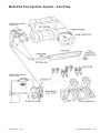
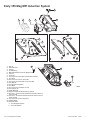
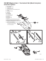
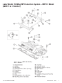
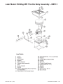
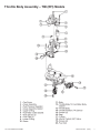
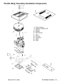
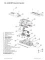
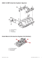

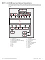
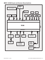
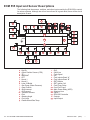
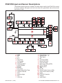
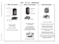
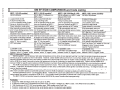
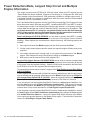
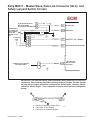
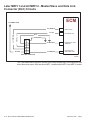
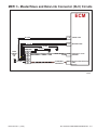
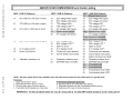
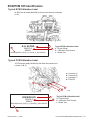
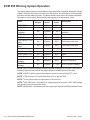
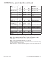
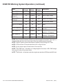
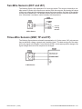
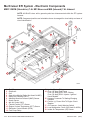
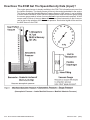
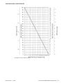
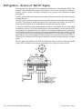
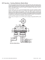
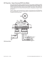
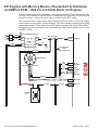
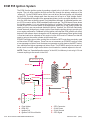

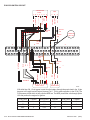
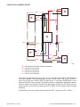
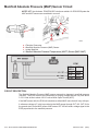
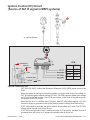

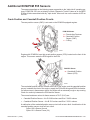
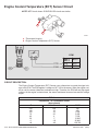
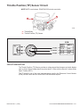
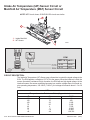
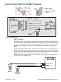
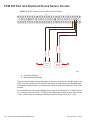

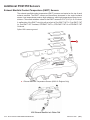
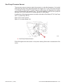
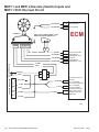
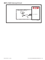
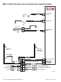
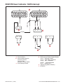
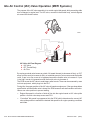
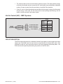
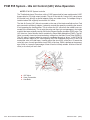
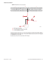
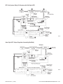
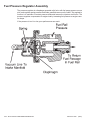
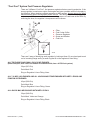
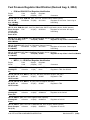
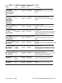
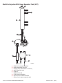
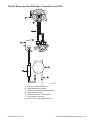
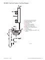
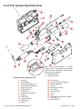
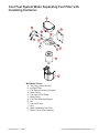
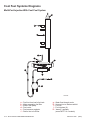
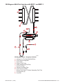
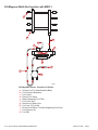
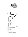
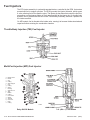
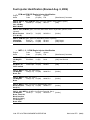
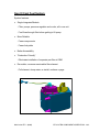
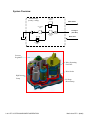
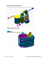
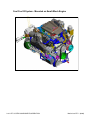
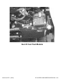

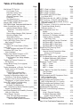
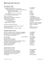
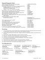

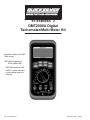
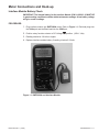
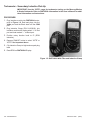
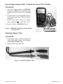
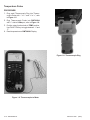
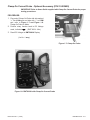
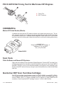
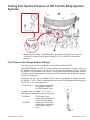
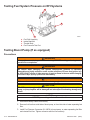
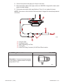
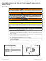
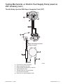
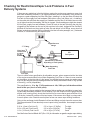
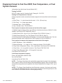
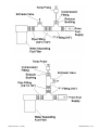
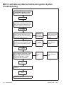
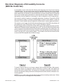
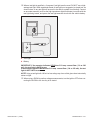

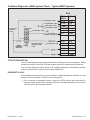
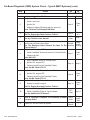
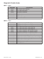
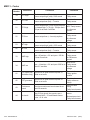
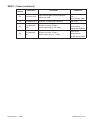
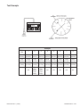
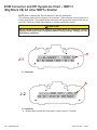
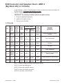
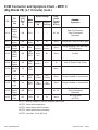
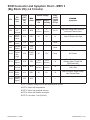
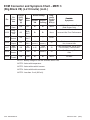
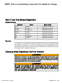
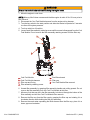
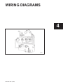
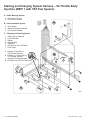
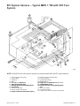
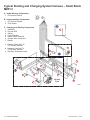
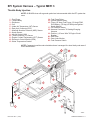
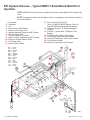
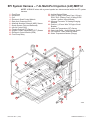
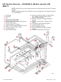
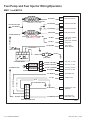
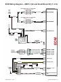
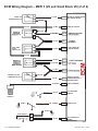
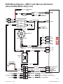
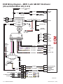
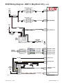
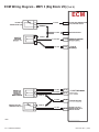
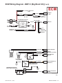
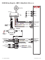
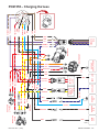
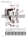
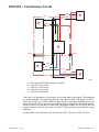

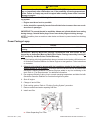
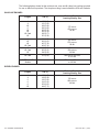

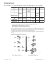
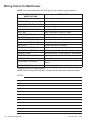


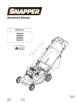
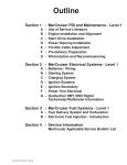

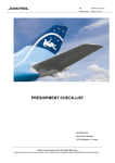

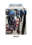
![[1 ] Oracle® Enterprise Manager](http://vs1.manualzilla.com/store/data/005669073_1-0396df232df5e560fdd03210f5126330-150x150.png)