1
DALSA • 7075 Place Robert-Joncas., Suite 142 • St-Laurent, Quebec, H4M 2Z2 • Canada
http://www.imaging.com
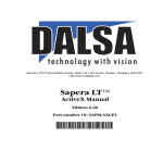
Sapera LT™
User’s Manual
Edition 6.00
part number OC-SAPM-USER0
*OC-SAPM-USER0*
NOTICE
© 2004-2006 DALSA Corp. All rights reserved.
This document may not be reproduced nor transmitted in any form or by any means, either electronic
or mechanical, without the express written permission of DALSA Corp. Every effort is made to ensure
the information in this manual is accurate and reliable. Use of the products described herein is
understood to be at the user's risk. DALSA Corp. assumes no liability whatsoever for the use of the
products detailed in this document and reserves the right to make changes in specifications at any time
and without notice.
Microsoft® is a registered trademark; Windows®, Windows NT®, Windows® 2000, and
Windows® XP are trademarks of Microsoft Corporation.
All other trademarks or intellectual property mentioned herein belong to their respective owners.
Printed on August 3, 2006
Document Number: OC-SAPM-USER0
Printed in Canada
Contents
INTRODUCTION ________________________________________________________________ 1
OVERVIEW OF SAPERA LT MANUALS ............................................................................................... 1
ABOUT THE MANUAL ........................................................................................................................ 2
USING THE MANUAL ......................................................................................................................... 2
GETTING STARTED_____________________________________________________________ 3
ABOUT SAPERA LT ........................................................................................................................... 3
SAPERA PRODUCTS............................................................................................................................ 4
TWAIN SUPPORT ............................................................................................................................. 4
MICROSOFT® DIRECTSHOW® SUPPORT ........................................................................................... 4
REQUIREMENTS ................................................................................................................................. 5
Minimum System Requirements................................................................................................. 5
Hardware Requirements (optional)........................................................................................... 5
INSTALLATION PROCEDURE............................................................................................................... 6
FILE LOCATIONS................................................................................................................................ 7
USING SAPERA LT ______________________________________________________________ 9
CONFIGURING SAPERA LT................................................................................................................. 9
Configuring Contiguous Memory............................................................................................ 10
Configuring Frame Grabber Board Serial Ports.................................................................... 10
USING THE CAMEXPERT TOOL ........................................................................................................ 11
Overview.................................................................................................................................. 11
Features................................................................................................................................... 11
Additional Information ............................................................................................................ 11
DEMOS AND EXAMPLES ................................................................................................................... 12
Acquiring with Grab Demo ..................................................................................................... 12
Description of Examples ......................................................................................................... 14
Description of Demos.............................................................................................................. 15
USING THE FLAT-FIELD DEMO ........................................................................................................ 19
Program Start and Server Selection........................................................................................ 19
Flat Field Demo Main Window............................................................................................... 20
Using Flat Field Correction.................................................................................................... 21
Flat Field Calibration ............................................................................................................. 22
USING THE APPLICATION WIZARD .................................................................................................. 24
Step 1 - Overview .................................................................................................................... 24
Step 2 - Define Source of Input Image .................................................................................... 27
Sapera LT User's Manual
Contents • i
Step 3 - Fine Tuning the User Interface .................................................................................. 28
Step 4 - Processing Images...................................................................................................... 29
Step 5 - Displaying Images...................................................................................................... 30
SAPERA LT ARCHITECTURE____________________________________________________ 31
APPLICATION ARCHITECTURE ......................................................................................................... 31
DEFINITION OF TERMS ..................................................................................................................... 32
DESCRIPTION OF SAPERA++ CLASSES ............................................................................................. 33
INTRODUCING THE SAPERA LT API_____________________________________________ 39
THE THREE SAPERA LT APIS .......................................................................................................... 39
CREATING A SAPERA++ APPLICATION ............................................................................................ 39
OBJECT INITIALIZATION AND CLEANUP ............................................................................................ 40
ERROR MANAGEMENT ..................................................................................................................... 42
CAPABILITIES AND PARAMETERS .................................................................................................... 43
ACQUIRING IMAGES ___________________________________________________________ 45
REQUIRED CLASSES ......................................................................................................................... 45
FRAME-GRABBER ACQUISITION EXAMPLE ...................................................................................... 45
Steps to perform an acquisition ............................................................................................... 45
MODIFYING THE FRAME-GRABBER PARAMETERS ........................................................................... 48
USING AN INPUT LOOKUP TABLE .................................................................................................... 50
CAMERA ACQUISITION EXAMPLE .................................................................................................... 51
MODIFYING THE CAMERA FEATURES .............................................................................................. 52
Accessing Feature Information and Values............................................................................. 52
Writing Feature Values by Group ........................................................................................... 56
DISPLAYING IMAGES __________________________________________________________ 57
REQUIRED CLASSES ......................................................................................................................... 57
DISPLAY EXAMPLE .......................................................................................................................... 57
DISPLAYING IN A WINDOWS APPLICATION ...................................................................................... 58
WORKING WITH BUFFERS _____________________________________________________ 61
ROOT AND CHILD BUFFERS ............................................................................................................. 61
BUFFER TYPES ................................................................................................................................. 62
READING AND WRITING A BUFFER .................................................................................................. 64
APPENDIX A: SUPPORT_________________________________________________________ 67
SUPPORTED OPERATING SYSTEMS ................................................................................................... 67
SUPPORTED DALSA DEVICES ........................................................................................................ 67
SYSTEM SUPPORT ............................................................................................................................ 68
APPENDIX B: OTHER TOOLS____________________________________________________ 69
DIRECTDRAW CAPABILITIES DETECTION TOOL .............................................................................. 69
FONT GENERATOR TOOL ................................................................................................................. 70
ii • Contents
Sapera LT User's Manual
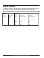
DALSA DIAGNOSTIC TOOL............................................................................................................. 70
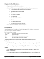
Overview: ................................................................................................................................ 70
Diagnostic Tool Features:....................................................................................................... 71
Usage Guide:........................................................................................................................... 71
APPENDIX C: SAPERA LT RUNTIMES ___________________________________________ 75
INTRODUCTION ................................................................................................................................ 75
INSTALLING SAPERA LT RUNTIMES AND SAPERA LT COMPATIBLE DRIVERS ................................. 75
DALSA Installers..................................................................................................................... 76
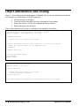
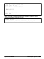
Silent Mode Installation .......................................................................................................... 77
DALSA CONTACT INFORMATION ______________________________________________ 79
SALES INFORMATION....................................................................................................................... 79
International/Canada .............................................................................................................. 79
USA ......................................................................................................................................... 79
TECHNICAL SUPPORT ...................................................................................................................... 80
GLOSSARY OF TERMS _________________________________________________________ 81
INDEX ________________________________________________________________________ 85
Sapera LT User's Manual
Contents • iii
iv • Contents
Sapera LT User's Manual
Introduction
Overview of Sapera LT Manuals
Sapera LT is supported by the following manuals in printed (with one exception), PDF, and compiled
HTML help formats.
• Sapera LT User’s Manual
Introduces Sapera LT and provides a general overview of its usage as well as installation
procedures.
• Sapera++ Programmer’s Manual
Describes in detail all the Sapera++ Basic and GUI classes. Sapera++ is based on the
C++ language.
• Sapera Basic Modules Reference Manual
Lists in detail the Sapera LT low-level module functions as well as data definitions, file
formats, and macros (based on the C language). This manual is not offered in printed
format.
• Sapera ActiveX Controls Programmer’s Manual
This manual explains how to program Sapera ActiveX controls.
• Sapera Acquisition Parameters Reference Manual
Describes the acquisition parameters and capabilities. This manual complements the
manuals that describe the different Sapera APIs (C, C++, Active X).
Sapera LT supports some hardware specific extensions (also referred to as board specific modules).
The following manuals, which are supplied with the corresponding hardware, describe the hardware
functionality and the supporting API.
• Sapera CAB Programmer's Manual
This manual introduces CAB (DALSA Coreco Auxiliary Bus) and explains how to
implement it into a functional system. It also describes the programming API.
• Sapera Pixel Processor Modules Programmer's Manual
This manual describes the Pixel Processor and its modules.
Sapera LT User's Manual
Introduction • 1
About the Manual
This manual exists in printed, Windows Help, and Adobe Acrobat® (PDF) formats. The Help and
PDF formats make full use of hypertext cross-references. The PDF format offers links to the DALSA
home page on the Internet, located at http://www.imaging.com, which contains documents, software
updates, demos, errata, utilities, and more.
Using the Manual
File names, directories, and Internet sites will be in bold text (for example, setup.exe, c:\windows,
http://www.imaging.com).
Source code, code examples, and text that must be entered using the keyboard will be in typewriterstyle text (for example, [PixelClock]).
Menu and dialog actions will be indicated in bold text in the order of the instructions to be executed,
with each instruction separated by bullets. For example, going to the File menu and choosing Save
would be written as File•Save.
2 • Introduction
Sapera LT User's Manual
Getting Started
About Sapera LT
Sapera LT is a high-level C++ class library dedicated to image processing and machine vision. The
C++ library API (Application Programming Interface) is composed of two different groups of classes:
• Basic Classes
• GUI Classes
The Basic Classes constitute the core of the Sapera++ API. They may be subdivided as follows:
• Manager Classes provide image device management functionality.
• Hardware Independent Classes provide everything you need to acquire, display and
access images without worrying about specific hardware.
• Board Specific Classes provide the hardware specific support functions. The Pixel
Processor and the Coreco Auxiliary Bus (CAB) modules are examples of Sapera LT
hardware specific extensions. Additional documentation is provided with the related
hardware products.
Hardware independent classes allow one application to control different DALSA devices through the
same API. It also guarantees seamless migration to any future DALSA hardware product supported by
Sapera LT. The modular architecture provides the user with high programming flexibility and
readability.
The GUI classes include a set of Microsoft® Foundation Classes (MFC) based dialog boxes designed
to implement some of the most commonly used tasks for Sapera LT applications, such as loading an
acquisition configuration file. They, however, do not constitute an official API. Rather, they are
provided 'as is' with source code so that you may modify them at your discretion.
Sapera LT User's Manual
Getting Started • 3
Sapera Products
Two different Sapera packages are available:
• Sapera LT
• Sapera Processing
Sapera LT includes everything you need to acquire and display images. It is targeted at developers
that have their own image processing libraries and want to interface those libraries to a Sapera LT
compatible device. Sapera LT includes tools such as CamExpert and the Sapera LT Application
Wizard to speed up application development.
Sapera Processing is DALSA's comprehensive C++ library for image processing and analysis.
Note: Despite the similarity in product names, these are two completely different products. They are
independent of one another, yet they can be used together to implement a complete image acquisition,
display, processing, and analysis solution. Refer to the Sapera Processing Programmer’s Manual for a
detailed description of Sapera Processing.
TWAIN Support
Initially developed to provide a standard software interface to image scanners, the TWAIN standard
has evolved into the imaging industry.
The TWAIN standard is a generic software interface between an application and an imaging device.
Sapera LT runtimes provide TWAIN support that allows a user to control DALSA devices through the
TWAIN interface without having to directly program any Sapera API.
Microsoft® DirectShow® Support
Sapera LT runtimes include a Microsoft® DirectShow® compatible driver that allows any Sapera LT
supported frame grabber to act as a DirectShow® video source.
4 • Getting Started
Sapera LT User's Manual
Requirements
Below is a list of the components required by Sapera LT.
Minimum System Requirements
•
•
•
PCI-bus IBM PC or compatible with Pentium class or later processor
Windows® 2000, Windows® XP (Note: Windows NT 4.0 and Embedded are no longer
officially supported)
One of the following C/C++ language compilers:
- Visual C++ version 6.0
- Visual C++ .NET 2003
- Visual C++ 2005
- Borland C++ Builder version 6.0 or later
OR
•
One of the following environments that support ActiveX technology:
- Visual Basic 6.0
- Visual Studio .NET 2003
- Visual Studio 2005
- Borland Delphi version 7
Hardware Requirements (optional)
•
•
One of several Sapera LT compatible devices (frame-grabber, processing board or
camera).
Corresponding Sapera LT-compatible device drivers.
Sapera LT User's Manual
Getting Started • 5
Installation Procedure
Note: Before installing Sapera LT, make certain that your current VGA display mode is set to display
at least 256 colors. Some Sapera LT features require DirectDrawTM, which will not work with a
smaller number of display colors.
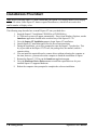
The following steps describe how to install Sapera LT onto your hard drive:
1. Insert the Sapera LT installation CD-ROM in a CD-ROM drive.
2. A CD Browser screen will appear automatically. If not, from Windows Explorer, run the
launch.exe application located in the root directory of the Sapera LT CD.
3. Go to the Sapera LT Installation menu to begin Sapera LT installation.
4. Launch Sapera LT installation and follow the on-screen instructions.
5. During the installation, you will be prompted to enter the Sapera LT product key. This
key is provided on the Sapera LT CD case, the package box, the manuals, and on a
separate sticker.
6. You can install the required board or camera drivers without rebooting the computer at
this time; however, you must reboot the computer to finish the installation of Sapera.
7. Reinsert the Sapera LT CD or run the launch.exe application again.
8. Go to the Hardware Device Drivers menu to install the required drivers for your
installed Sapera LT supported hardware.
9. Reboot the computer when prompted to complete the software installation.
6 • Getting Started
Sapera LT User's Manual
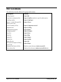
File Locations
The table below lists the different file groups and locations:
Description
Location
Utility programs
\Sapera\Bin
Acquisition configuration files
\Sapera\CamFiles (and device-specific subdirectories)
CamExpert utility
\Sapera\CamExpert
Sapera++ include files and GUI
classes source code
\Sapera\Classes
ActiveX controls (OCXs)
\Sapera\Components\ActiveX
Diagnostic tool
\Sapera\CorDiag
Demonstration programs
\Sapera\Demos
Example programs
\Sapera\Examples
Font files
\Sapera\Fonts
Help files
\Sapera\Help
Image files
\Sapera\Images
Header files
\Sapera\Include
Import libraries
\Sapera\Lib
Pixel processor high level library
source code
\Sapera\Pixpro
Dynamic-link libraries (DLLs)
Windows system directory (windows\system32)
Device driver files
Windows driver directory (windows\system32\drivers)
Sapera LT User's Manual
Getting Started • 7
8 • Getting Started
Sapera LT User's Manual
Using Sapera LT
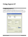
Configuring Sapera LT
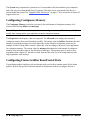
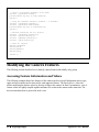
The Sapera LT Configuration program (SapConf.exe) allows you to see all the Sapera LTcompatible devices present within your system, together with their respective serial numbers. It may
also be used to adjust the amount of contiguous memory to be allocated at boot-time. After activating
this program, it displays all the servers related to the installed devices as shown in the figure below.
Sapera LT User's Manual
Using Sapera LT • 9
The System entry represents the system server. It corresponds to the host machine (your computer),
and is the only server that should always be present. The other servers correspond to the device’s
present within the system. See "Supported DALSA Devices" on page 67 for a current list of Sapera LT
supported devices.
Configuring Contiguous Memory
The Contiguous Memory section lets you specify the total amount of contiguous memory to be
reserved for allocating buffers and messages.
Note: All Sapera LT demos and examples do not use contiguous memory. Therefore, you should not
modify these settings unless your application requires contiguous memory.
The Requested value displays what was requested. The Allocated value displays the amount of
contiguous memory that was allocated successfully. The current value for buffers determines the total
amount of contiguous memory reserved at boot-time for the allocation of dynamic resources (for
example, buffers, lookup tables, kernels). Adjust this value according to the need of your application
for contiguous memory. The current value for messages determines the total amount of contiguous
memory reserved at boot-time for the allocation of messages. This memory space is used to store
arguments when a Sapera LT function is called. Increase this value if you are using functions with
large arguments, such as arrays.
Configuring Frame Grabber Board Serial Ports
Certain frame grabber boards provide an onboard serial port for direct camera control by the frame
grabber. Refer to the specific board user manual for information on how to configure and use it.
10 • Using Sapera LT
Sapera LT User's Manual
Using the CamExpert Tool
Overview
Sapera LT applications need to load the appropriate acquisition configuration file before acquiring
images from a camera. The camera configuration file has the extension .ccf .
CamExpert, provided with Sapera LT, supplies sets of predefined camera files for the most common
camera types (including NTSC and PAL). Use CamExpert to generate a CCF file in which you have a
camera for which there are currently no available CAM files.
Features
•
Supports all DALSA hardware currently supported by Sapera LT.
•
Creates and modifies camera configuration (CCF or CCA/CVI) files.
•
Groups acquisition parameters into related categories for easier access to any specific
parameter.
•
Intelligent editing of video timings through a locking mechanism that allows explicit
modification of some values and automatic recalculation of the remaining ones.
•
Online operation mode that allows live acquisition of images as the parameters are specified
and modified.
•
Online context-sensitive help system.
Additional Information
For additional information about Sapera acquisition parameters, refer to the Sapera Acquisition
Parameters Reference Manual.
See either the corresponding device user’s manual or search within this manual for limitations
applicable to specific DALSA hardware.
Sapera LT User's Manual
Using Sapera LT • 11
Demos and Examples
Several generic demos and examples come with Sapera. A description is provided for each in this
section.
Certain device driver installations provide other demos and examples that demonstrate the specific
usages and capabilities of the device. Refer to a specific device user’s manual for further details.
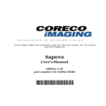
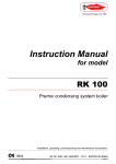
Acquiring with Grab Demo
The Sapera LT Grab Demo program allows you to grab and display a live image in a host buffer.
It can accommodate any Sapera-compatible board with any camera. This demo is a good starting
point to verify that your camera and frame grabber are properly installed.
The following dialog box appears when starting Grab Demo:
You must select the Acquisition Server and the Acquisition Device. The first one corresponds to
the board you want to grab from; the second represents the acquisition device on this board (some
boards may have more than one).
You must then select an acquisition configuration file (CCF File) compatible with your camera
from the list of available files. CamExpert must be used to generate CCF files (for example,
external trigger, cropping window, and so forth).
Note: No frame grabber was found within your system if this dialog box does not appear. In such a
case, verify that the device driver corresponding to your frame grabber was correctly installed. The
Sapera LT Configuration Program gives you a list of boards present within your system. This demo
can work without a frame grabber. It, however, only allows you to load the file from the disk.
Click OK to start the demo.
12 • Using Sapera LT
Sapera LT User's Manual
By using Grab Demo you can now:
•
Control the acquisition using the Snap, Grab, Freeze, and Abort buttons.
•
Load/save images from/to disks using the Load and Save buttons.
•
Dynamically adjust the acquisition parameters through the General, Area scan, Linescan,
and Composite buttons.
•
Reload the CCF file using the Load Config button (this overwrites all the parameters
modified in step 3).
•
The Buffer button allows you to change the number of buffers used for internal cycling and
the type of buffer used (contiguous, scatter-gather, off-screen, or overlay).
Sapera LT User's Manual
Using Sapera LT • 13
Description of Examples
Several example programs are available within Sapera. They are essentially basic applications
demonstrating simple tasks like grabbing an image and loading an image file from the disk.
The main purpose of the examples is to provide the user with code samples that can be easily extracted
and integrated into an application.
All the examples are included in the following projects:
Sapera\Examples\Classes\SapExamples.dsw (for Microsoft Visual C++ 6.0)
Sapera\Examples\Classes\SapExamples_2003.sln (for Microsoft Visual C++.NET
2003)
Sapera\Examples\Classes\SapExamples_2005.sln (for Microsoft Visual C++ 2005)
Sapera\Examples\Classes\SapExamples.bpg (for Borland C++ Builder)
These projects allow you to recompile all the examples in a batch.
The table below describes the different example programs:
FileLoadCPP Example
This example shows how to load an image file from the disk into a Sapera buffer and then display it. The
buffer is created according to the image file properties. One of several images (monochrome, RGB, or YUV)
can be selected for loading. This example uses the Sapera C++ API.
FileLoadMFC Example
Same as the FileLoadCPP Example, but additionally uses the Sapera++ GUI classes allowing file browser
usage.
GrabCPP Example
This example shows how to grab an image from a selected camera into a Sapera buffer and then display it.
The buffer is created according to the camera settings. Any Sapera compatible frame grabber can be used.
This example uses the Sapera C++ API.
GrabMFC Example
Same as GrabCPP but additionally uses the GUI Sapera++ classes to allow for board and camera selection
using dialog boxes.
ColorSplit Example
Shows how to split and merge color images into single monochrome components. An RGB image is loaded,
split into three monochrome components, then a simple processing is applied to the three components before
they are merged back to RGB as output.
14 • Using Sapera LT
Sapera LT User's Manual
Description of Demos
Several demo programs are available with Sapera. They are more complete applications than the
supplied examples. There are demos that cover both Sapera++ and the ActiveX controls.
The demos main purpose is to provide the user with a starting application that can be modified in order
to become the user’s end application.
A Visual Studio 6.0 workspace (\Sapera\Demos\Classes\Vc\SapDemos.dsw) and a Visual Studio
.NET 2003 solution (\Sapera\Demos\Classes\Vc\SapDemos_2003.sln) include all Sapera++ demo
projects. They allow you to recompile all the demos in a batch, together with the Sapera++ GUI
Classes.
The following describes the different Sapera++ demo programs. See the Sapera++ Programmer’s
Manual for more information on the Sapera++ API.
Grab Demo (Dialog Box Interface)
\Sapera\Demos\Classes\Vc\GrabDemo\Release\GrabDemo.exe
This program demonstrates the basic acquisition functions included in Sapera++. It allows you to acquire
images, either in continuous or in one-shot mode, while adjusting the acquisition parameters.
The minimum requirements to run this demo are a Sapera-compatible frame grabber and an analog or digital
camera.
The supplied executable is built using Visual Studio .NET 2003, plus the MFC library.
Grab Demo (Single Document Interface)
\Sapera\Demos\Classes\Vc\GrabDemoSDI\Release\GrabDemoSDI.exe
This program demonstrates the basic acquisition functions included in Sapera++. It allows you to acquire
images, either in continuous or in one-shot mode, while adjusting the acquisition parameters.
The minimum requirements to run this demo are a Sapera-compatible frame grabber and an analog or digital
camera.
The supplied executable is built using Visual Studio .NET 2003, plus the MFC library.
Grab Demo (Multiple Document Interface)
\Sapera\Demos\Classes\Vc\GrabDemoMDI\Release\GrabDemoMDI.exe
This program demonstrates the basic acquisition functions included in Sapera++. It allows you to acquire
images, either in continuous or in one-shot mode, while adjusting the acquisition parameters. You can open
multiple windows to simultaneously acquire and display images from separate cameras.
The minimum requirements to run this demo are a Sapera-compatible frame grabber and an analog or digital
camera.
No shortcut to this demo is provided in the Start menu for Sapera LT. However, an executable built using
Visual Studio .NET 2003 and the MFC library is supplied under the
\Sapera\Demos\Classes\Vc\GrabDemoMDI directory.
Sapera LT User's Manual
Using Sapera LT • 15
Sequential Grab Demo
\Sapera\Demos\Classes\Vc\SeqGrabDemo\Release\SeqGrabDemo.exe
This program demonstrates how to grab a sequence of images into memory and then display them. The
program allows you to record several images and then load and save AVI files. Each image is stored in its
own buffer and can be reviewed. A small number of images are allocated by default, but they can be
increased using the buffer options inside the demo.
The minimum requirements to run this demo are a Sapera-compatible frame grabber and an analog or digital
camera.
No shortcut to this demo is provided in the Start menu for Sapera LT. However, an executable built using
Visual Studio .NET 2003 and the MFC library is supplied under the
\Sapera\Demos\Classes\Vc\GrabDemoMDI directory.
Bayer Demo
\Sapera\Demos\Classes\Vc\BayerDemo\Release\BayerDemo.exe
This program demonstrates the Bayer conversion functionality included in Sapera++. It allows you to acquire
images, either in continuous or in one-shot mode, while adjusting the acquisition parameters. It includes
interactive control of Bayer conversion parameters. You may optionally apply Bayer filtering to acquired
images.
The minimum requirements to run this demo are a Sapera-compatible frame grabber and an analog or digital
monochrome camera.
The supplied executable is built using Visual Studio .NET 2003, plus the MFC library.
Flat-field Demo
\Sapera\Demos\Classes\Vc\FlatFieldDemo\Release\FlatFieldDemo.exe
This program demonstrates the flat-field correction functionality included in Sapera++. Flat Field Correction
(FFC) includes Fixed Pattern Noise (FPN), Pixel Replacement, Photo Response Non Uniformity (PRNU),
and Shading Correction. The demo allows you to acquire images, either in continuous or in one-shot mode,
while adjusting the acquisition parameters. It includes interactive calibration of flat-field gain and offset
settings. You may optionally apply flat-field correction to acquired images.
The minimum requirements to run this demo are a Sapera-compatible frame grabber and an analog or digital
monochrome camera.
The supplied executable is built using Visual Studio .NET 2003, plus the MFC library.
I/O Demo
\Sapera\Demos\Classes\Vc\IODemo\Release\IODemo.exe
This program demonstrates the usage of General I/O functionality included in Sapera++. It allows you to
monitor the current state of the input and output pins, and change their state between low and high polarity. It
also allows you to monitor interrupts on the input pins, and to count the number of incoming interrupts.
The minimum requirements to run this demo are a Sapera-compatible board with General I/O capabilities.
The supplied executable is built using Visual Studio .NET 2003, plus the MFC library.
16 • Using Sapera LT
Sapera LT User's Manual
GigE-Vision Camera Demo
\Sapera\Demos\Classes\Vc\GigeCameraDemo\Release\GigeCameraDemo.exe
This program demonstrates how to acquire images from a DALSA GigE Vision™ camera. The demo allows
either to load a configuration file (previously generated by CamExpert) or to use the camera defaults.
The minimum requirement to run this demo is a Sapera-compatible GigE-Vision camera.
The supplied executable is built using Visual Studio .NET 2003, using the MFC library.
Sapera LT also includes demos that use ActiveX controls. A Visual Basic 6.0 project group
(\Sapera\Demos\ActiveX\Vb6\SapActiveXDemos.vbg), Visual Studio .NET 2003 solution
(\Sapera\Demos\ActiveX\.NET\SapActiveXDemos.sln), and Delphi 7 package solution
(\Sapera\Demos\ActiveX\Delphi\SapActiveXDemos.bpg) include all ActiveX demo projects.
The following describes the different Sapera LT ActiveX demo programs. . See the Sapera LT ActiveX
Controls Manual for more information on the ActiveX controls.
Acquisition Demo (Visual Basic 6.0)
\Sapera\Demos\ActiveX\Vb6\AcqDemo\AcqDemo.exe
This program demonstrates the basic acquisition functions included in the Sapera LT ActiveX controls. It
allows you to load an acquisition file and then acquire images, either in continuous or in one-shot mode.
Clicking the right mouse button over the image display area allows you to modify the acquisition control
properties as well as loading and saving images.
The minimum requirements to run this demo are a Sapera-compatible frame grabber and an analog or digital
camera.
The supplied executable is built using Visual Basic 6.
Acquisition Demo (VB.NET)
\Sapera\Demos\ActiveX\.NET\VbAcqDemo\VbAcqDemo.vbproj
This program demonstrates the basic acquisition functions included in the Sapera LT ActiveX controls. It
allows you to load an acquisition file and then acquire images, either in continuous or in one-shot mode.
Clicking the right mouse button over the image display area allows you to modify the acquisition control
properties as well as loading and saving images.
The minimum requirements to run this demo are a Sapera-compatible frame grabber and an analog or digital
camera.
Acquisition Demo (C#)
\Sapera\Demos\ActiveX\.NET\VsAcqDemo\VsAcqDemo.csproj
This program demonstrates the basic acquisition functions included in the Sapera LT ActiveX controls. It
allows you to load an acquisition file and then acquire images, either in continuous or in one-shot mode.
Clicking the right mouse button over the image display area allows you to modify the acquisition control
properties as well as loading and saving images.
The minimum requirements to run this demo are a Sapera-compatible frame grabber and an analog or digital
camera.
Sapera LT User's Manual
Using Sapera LT • 17
Acquisition Demo (Delphi 7)
\Sapera\Demos\ActiveX\Delphi\AcqDemo\AcqDemo.dpr
This program demonstrates the basic acquisition functions included in the Sapera LT ActiveX controls. It
allows you to load an acquisition file and then acquire images, either in continuous or in one-shot mode.
Clicking the right mouse button over the image display area allows you to modify the acquisition control
properties as well as loading and saving images.
The minimum requirements to run this demo are a Sapera-compatible frame grabber and an analog or digital
camera.
18 • Using Sapera LT
Sapera LT User's Manual
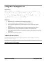
Using the Flat-Field Demo
Program
Start•Programs•DALSA•Sapera LT•Demos•Flat Field Demo
Program file
\DALSA Coreco\Sapera\Demos\Classes\vc\FlatFieldDemo\Release\FlatfieldDemo.exe
Description
This program demonstrates Flat Field (2D Shading Correction) or Flat Line processing (1D
Shading Correction), either performed by supporting DALSA hardware or performed on the
host system via the Sapera library. The program allows you to acquire a flat field or flat line
reference image, and then do real time correction either in continuous or single acquisition
mode. The program code may be extracted for use within your own application.
Remarks
This demo is built using Visual C++ 6.0 using the MFC library. It is based on Sapera C++
classes. See the Sapera User’s and Reference manuals for more information.
Flat Field Correction is the process of eliminating small gain differences between pixels in a CCD
array. When calibrated flat field correction is applied to the image, the CCD exposed to a uniformly
lighted field will have no gray level differences between pixels. The Flat Field demo automatically
functions both with hardware supporting flat field processing or performs the processing via the
Sapera library on the host system processor.
Program Start and Server Selection
Run the demo via the Windows start menu shortcut Start•Programs•DALSA•Sapera
LT•Demos•Flat Field Demo. The demo program first displays the acquisition configuration menu to
select the board acquisition server and acquisition device.
If the selected board does not support onboard flat field processing, a message is displayed (see
following figure) stating that processing will be on the host system.
This menu is also used to select the required camera configuration file for the connected camera. For a
more detailed description of the acquisition configuration menu see "Acquiring with Grab Demo" on
page 12. Sapera camera files contain timing parameters and video conditioning parameters.
Sapera LT User's Manual
Using Sapera LT • 19
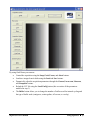
Flat Field Demo Main Window
The demo main window provides control buttons and a central area for displaying the grabbed image.
Developers can use the demo source code as a foundation to quickly create and test the desired
imaging application.
20 • Using Sapera LT
Sapera LT User's Manual
Using Flat Field Correction
The demo has typical file and acquisition controls as previously described for the Grab Demo. What is
different is the Flat Field Correction control section which has three buttons and a check box. Follow
the procedure described below to setup and use flat field correction.
Verify camera acquisition
First ensure that the camera is functioning and that the acquisition board is capturing live images. The
Flat Field Demo provides acquisition controls to confirm image capture.
Enable
Before activating flat field or flat line correction, follow the calibration procedure described in this
section (see "Flat Field Calibration" on page 22). To use real time flat field correction, first click in the
Enable box. Then do image snaps or continuous live grab.
Save
Click on the Save button to store files with the flat field gain and offset data gathered with the
calibration procedure. Files are saved as .bmp images and can be named as required to reference the
camera used.
Load
Click on the Load button to retrieve files with the flat field gain and offset data gathered with the
calibration procedure.
Sapera LT User's Manual
Using Sapera LT • 21
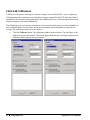
Flat Field Calibration
Calibration is the process of taking two reference images, one of a black field – one of a light gray
field (not saturated), to generate correction data for images captured by the CCD. Each pixel data is
modified by the correction factor generated by the calibration process, so that each pixel now has an
identical response to the same illumination.
The calibration process for an area scan camera can be over the whole frame or a selected number of
lines within the frame. For line-scan cameras the user simply selects the number of input lines to
average. The calibration control overview follows.
•
Click the Calibrate button. The calibration window opens as shown. The first figure is the
default for an area scan camera. The second figure shows the user selecting a single line for
calibration when using an area scan camera.
22 • Using Sapera LT
Sapera LT User's Manual
Setup Before Calibration
•
First select the correction type to flat field or single flat line. Note that when using a linescan camera, only flat line calibration is available.
•
Video type will default to the acquisition type defined in the loaded camera file.
•
Set the number of frames to average during each calibration step. This should be set to
more then one to avoid false data from random pixel noise.
•
The field for maximum deviation from average defaults to 25% of the gray level range
captured, (64 for 8-bit capture, 256 for 10-bit capture, and so forth). This value sets the
threshold for detecting static dead pixels – both dark or light. Users will need to adjust this
field to best isolate dead pixels from their imaging source.
•
When doing a single line calibration to apply to the captured frame, use the two selection
fields number of lines to average and vertical offset from top, to select which video line
will be used.
Calibration
•
Setup the camera to capture a uniform black image. Black paper with no illumination and the
camera lens’ iris closed to minimum can provide such a black image.
•
Click on Acquire Black Image. The flat field demo will grab a video frame, analyze the
pixel gray level spread, and present the statistics. If acceptable, use the image as the black
reference.
•
Setup the camera to acquire a uniform white image (but not saturated white). Even
illumination on white paper can be used. It is preferable to prepare for the white level
calibration before the calibration procedure.
•
Click on Acquire White Image. The flat field demo will grab a video frame, analyze the
pixel gray level spread, and present the statistics. If acceptable, use the image as the white
reference.
•
Test the calibration by enabling flat field correction during a live grab. If necessary, adjust the
dead pixel detection threshold and repeat the calibration.
•
Save multiple versions of calibration data to compare for best imaging or for different
imaging setups.
Sapera LT User's Manual
Using Sapera LT • 23
Using the Application Wizard
Step 1 - Overview
The Sapera LT Application Wizard allows code generation for simple applications involving a single
acquisition device (for example, Bandit-II) in a host computer. It is called from within Microsoft
Visual Studio 6, by selecting File•New and then selecting the Projects tab.
The Sapera LT Application Wizard generates dialog-based MFC applications that use the Sapera++
classes introduced with Sapera 4.0.
Sapera++ Basic Classes encapsulate all Sapera API calls. They address basic imaging concepts, that is,
acquisition, display, processing, and buffers.
Sapera++ GUI Classes provide the user with MFC-based dialog boxes commonly used in most
imaging applications.
Refer to Sapera++ Programmer’s Manual for information on the classes.
24 • Using Sapera LT
Sapera LT User's Manual
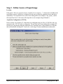
The screen shot below is the first to appear after starting the Sapera LT Application Wizard, and
describes what the Sapera LT Application Wizard can essentially do.
Sapera LT User's Manual
Using Sapera LT • 25
Below is a typical user application interface obtained by using the Sapera LT Application Wizard.
26 • Using Sapera LT
Sapera LT User's Manual
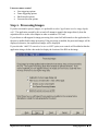
Step 2 - Define Source of Input Image
Location
If the option “Select an acquisition device installed in host computer...” is chosen (not available in the
stand-alone version) a dialog box is displayed for the user to chose the acquisition server and device
immediately. The acquisition server refers to the frame grabber (for example, Viper_Quad_1) while
the acquisition device is the name of the input device (for example, Single Channel 1).
Acquisition Configuration (CCF file)
Prior to release 5.0 of Sapera LT, acquisition was configured using two files: a CAM file (with .cca
extension) and a VIC file (with .cvi extension). The two files have been combined into a single CCF
file that you can generate using the CamExpert tool. CamExpert uses a large database of CAM files
that are distributed with Sapera LT and cover a wide range of camera manufacturers and models.
Sapera LT User's Manual
Using Sapera LT • 27
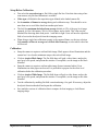
Step 3 - Fine Tuning the User Interface
It is sometimes more convenient to set some acquisition parameters individually and directly from
within the application rather than using CamExpert. Sapera Classes define a few standard GUI dialog
boxes that allow the user to change a selection of frequently used parameters. The screen shot below
shows the category list of parameters you can enable.
Below is a brief description of parameters that can be accessed via the different categories:
Video-input-conditioning
• Brightness and contrast options
• Hue and saturation options
Miscellaneous controls
• Camera selector
• Digital input connect bit ordering
• External trigger options
Area scan camera control
• Trigger/reset/integrate options
• Master mode (camera slave) options
28 • Using Sapera LT
Sapera LT User's Manual
Linescan camera control
• Line triggering options
• Frame triggering options
• Shaft encoder options
• Linescan direction options
Step 4 - Processing Images
If you do not intend to process images, it is preferable to select “Application involves image display
only”. The application created by this wizard will attempt to transfer the images directly from the
acquisition device to the video adapter in order to minimize CPU load.
If you choose to add support for image processing, this wizard will add controls to the application for
the user to enable/disable image processing. If the processing is enabled, the processed images will be
displayed; otherwise, the unprocessed images will be displayed.
If you select the “Add GUI controls to let user set ROI” option, user controls will be added within the
application along with the code needed to display the location of the ROI on the image.
Sapera LT User's Manual
Using Sapera LT • 29
Step 5 - Displaying Images
If you select the “Enable graphics overlay” option, the wizard will write code that will attempt to use
the display adapter’s overlay hardware acceleration. If it is not available, then the overlay will be
drawn by software for each displayed frame.
Event Notification
For synchronization purposes, you may register your functions called by Sapera LT at specific events,
like at the end of a frame’s acquisition. In this step, you can select which events will trigger a Sapera
LT Application Wizard written function to be called. Note that some events may have been
automatically selected depending on your answers in the previous steps of the wizard.
30 • Using Sapera LT
Sapera LT User's Manual
Sapera LT Architecture
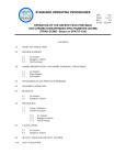
Application Architecture
Whichever API is used (Sapera++, Standard C, or ActiveX), the Sapera LT modular architecture
allows applications to be distributed on different Sapera LT servers. Each server can run either on the
host computer or on a DALSA device. Sapera LT calls are routed to different servers via the Sapera
LT messaging layer in a fashion completely independent to the underlying hardware.
User Application
Sapera++ (C++)
ActiveX Controls
Standard API (C)
Host Server
Messaging Layer
Sapera
Modules
Board 1 Server
Board 2 Server
Sapera
Modules
Sapera
Modules
Sapera LT User's Manual
Board N Server
...
Sapera
Modules
Sapera LT Architecture • 31
Definition of Terms
What is a server?
A Sapera LT server is an abstract representation of a physical device like a frame grabber, a processing
board, a GigE camera or a desktop PC. In general, a DALSA board is a server. Some processing
boards, however, may contain several servers; this is true when using multi-processor boards.
A server allows Sapera LT applications to interact with the server’s resources.
What is a static resource?
Resources attached to a physical device are called static resources. For example, a frame grabber can
have an acquisition resource and a transfer resource. These resources can be manipulated to control a
physical device through a Sapera LT server.
What is a dynamic resource?
A dynamic resource is an abstract representation of data storage (such as a buffer, lookup table, and so
forth), or links that connect the data storage to static resources. Unlike static resources, dynamic
resources are not dependent on physical devices; therefore, users on a specified server can freely
create dynamic resources.
What is a module?
A module is a set of functions used to access and/or control a static or a dynamic resource. The
complete Sapera LT Standard C API is composed of a series of modules organized in a particular
architecture. See the Sapera Basic Modules Reference Manual for details.
Sapera++ encapsulates all of these concepts in a series of C++ classes that offer the following benefits
compared to the Standard API
• Easier server management
• Consistent programming interface for static and dynamic resources
• Grouping of modules inside one class whenever appropriate
See the Sapera++ Programmer’s Manual for a hierarchy chart of all the Sapera++ classes.
32 • Sapera LT Architecture
Sapera LT User's Manual
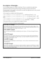
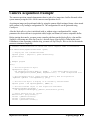
Description of Sapera++ Classes
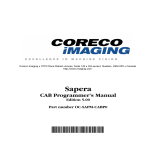
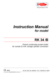
Below is a diagram along with a brief description of the main Sapera++ classes that implement access
to the Standard API module resources, as well as their relationship to other classes.
S a p e ra + + B a s ic C la s s e s (B y S u b je c t)
G e n e ra l C la s s e s
SapM anager
S a p L o c a tio n
S a p M a n C a llb a c k In fo
S a p D a ta
D a ta C la s s e s
(S a p D a ta X X X )
A c q u is itio n C la ss e s
F ra m e -G ra b b e r S p e cific
C a m e ra S p e c ific
G e n e ra l
S a p A c q u is itio n
S a p A c q D e v ic e
SapLut
S a p A c q C a llb a c k In fo
S a p A c q D e v ic e C a llb a c k In fo
S a p F la tF ie ld
S a p B a ye r
S a p F e a tu re
B u ffe r C la s s e s
T ra n s fe r C la s s e s
S a p B u ffe r
S a p T ra n s fe r
S a p X fe rP a ir
S a p B u ffe rW ith T ra s h
S p e c ia liz e d T ra n s fe r C la s s e s
(S a p X X X T o Y Y Y )
S a p X fe rP a ra m s
S a p X fe rC a llb a c k In fo
S a p B u ffe rR o i
S a p X fe rN o d e
D is p la y & G ra p h ic s C la s s e s
I/O C la s s e s
S a p V ie w
S a p G io
SapCab
S a p P ix P ro
S a p V ie w C a llb a c k In fo
S a p G io C a llb a c k In fo
SapDsp
S a p C o u n te r
S a p D is p la y
L e g a c y C la ss e s
S a p B u ffe rR e m o te
P ro ce s s in g C la ss e s
S a p G ra p h ic
S a p P ro c e s s in g
S a p P ro C a llb a c k In fo
S a p P ix P ro P a ra m s
S a p C o u n te rC a llb a c k In fo
S a p P e rfo rm a n c e
Sapera LT User's Manual
Sapera LT Architecture • 33
SapAcquisition Class
The SapAcquisition class includes the functionality to control an acquisition device on any DALSA
board that supports an acquisition section (for example, X64-CL). It is used as a source transfer node
to allow data transfers from an acquisition resource to another transfer node, such as SapBuffer,
SapCab, SapDsp, or SapPixPro. It is used by the SapTransfer class.
SapAcqDevice Class
The SapAcqDevice class includes the functionality to control an acquisition device on any DALSA
camera (for example, Genie M640). It is used as a source transfer node to allow data transfers from an
acquisition resource to another transfer node, such as SapBuffer. It is used by the SapTransfer class.
SapBuffer Class
The SapBuffer class includes the functionality to manipulate an array of buffer resources. A SapBuffer
object can be used by a SapTransfer object as a destination transfer node to allow data transfers from a
source node, such as SapAcquisition, SapDsp, SapPixProcessor, SapCab, or another SapBuffer. It may
also be used as a source transfer node to allow transferring data to another SapBuffer or a SapCab.
A SapBuffer object can be displayed using the SapView class and processed using the SapProcessing
class. It may also be the destination of graphic drawing operations through the SapGraphic class.
SapCab Class
The SapCab class includes the functionality to manipulate a CAB resource. It may be used by a
SapTransfer object as a destination transfer node to allow data transfer from a source node, such as
SapAcquisition, SapBuffer, SapDsp, SapPixPro, or another SapCab. It may also be used as a source
transfer node to allow data transfers to a SapBuffer or another SapCab.
For more information, consult the Sapera CAB Programmer’s Manual.
SapCounter Class
The purpose of the SapCounter class is to count events. These events can be external, such as a user
supplied signal, or internal, such as a hardware clock. The counter may then be used as a reference to
control events, such as changing the state of a general I/O at a specific time (together with the SapGio
class). It may also be used to timestamp acquired images (SapBuffer objects), or to monitor the
progression of an application (by simply reading the counter value).
SapDisplay Class
The SapDisplay class includes functionality to manipulate a display resource on the system display
device (your computer video card) or any DALSA board supporting a display section. There is at least
one such resource for each display adapter (VGA board) in the system.
Note that SapView objects automatically manage an internal SapDisplay object for the default display
resource. However, you must explicitly manage the object yourself if you need a display resource
other than the default one.
SapFeature Class
34 • Sapera LT Architecture
Sapera LT User's Manual
The SapFeature class includes the functionality to retrieve the feature information from the
SapAcqDevice class. Each feature supported by the SapAcqDevice class provides a set of capabilities
such as name, type, access mode, and so forth, that can be obtained through the feature module.
SapGio Class
The purpose of the SapGio class is to control a block of general inputs and outputs, that is, a group of
I/Os that may be read and/or written all at once. This class may be used together with SapCounter to
associate event counting with the state of specific I/O pins.
SapGraphic Class
The SapGraphic class implements the drawing of graphic primitives and text strings. It supports these
operations either destructively on image data itself (using the Standard API graphic module), or in
non-destructive overlay over displayed images (using Windows GDI functions).
SapLut Class
The SapLut class implements lookup table management. It is usually used together with the
SapAcquisition and SapView classes to respectively manipulate acquisition and display lookup tables.
SapPixPro Class
The SapPixPro class includes the functionality to manipulate resources on a pixel processor device,
that is, a daughter card that plugs into certain DALSA boards. The Pixel Processor is often used for
applying simple pre-processing to an image. It is used by a SapTransfer object as an intermediate
transfer node to allow data transfers from an acquisition resource to another transfer node, such as
SapBuffer or SapCab.
SapTransfer Class
The SapTransfer class implements functionality for managing a generic transfer process, that is, the
action of transferring data from one source node to a destination node.
All the following classes are considered to be transfer nodes: SapAcquisition, SapBuffer, SapCab,
SapDsp, and SapPixPro.
SapView Class
The SapView class includes the functionality to show the resources of a SapBuffer object in a window
through a SapDisplay object. An ‘auto empty’ mechanism allows synchronization between SapView
and SapTransfer objects in order to show buffers in realtime without missing any data.
Sapera++ also includes classes that implement access either to a subset of the functionality of a
Standard C API resource, or to functionality taken from two or more Standard C API resources. There
are also some classes that are completely independent of this lower layer.
Data Classes
SapData and its derived classes act as wrappers for low-level Sapera LT data types, where each class
encapsulates one data element of a specific type. They are used as method arguments or return values
in various Sapera++ classes.
SapAcqCallbackInfo Class
Sapera LT User's Manual
Sapera LT Architecture • 35
The SapAcqCallbackInfo class acts as a container for storing all arguments to callback functions for
the SapAcquisition class.
SapAcqDeviceCallbackInfo Class
The SapAcqDeviceCallbackInfo class acts as a container for storing all arguments to callback
functions for the SapAcqDevice class.
SapBayer Class
The purpose of the SapBayer class is to support Bayer conversion on images acquired from a camera.
It supports this functionality both from the acquisition hardware (if supported) or from a software
implementation.
SapBufferRoi Class
The purpose of the SapBufferRoi class is to create a rectangular region of interest (ROI) inside an
existing SapBuffer object. The ROI has the same origin and dimensions for all buffer resources in the
object.
SapBufferWithTrash Class
The SapBufferWithTrash class creates an additional resource called the trash buffer used when
transferring data in real-time applications.
The trash buffer is an emergency buffer used when the data transfer is faster than a processing task
performed on the buffers. When processing is not fast enough to keep up with the incoming data,
images are transferred temporarily into the trash buffer until stability is reestablished.
SapCounterCallbackInfo Class
The SapCounterCallbackInfo class acts as a container for storing all arguments to callback functions
for the SapCounterclass.
SapFlatField Class
The purpose of the SapFlatField class is to perform flat-field correction on images acquired from a
camera or loaded from a disk. It supports this functionality both from the acquisition hardware (if
supported) or from a software implementation.
SapGioCallbackInfo Class
The SapGioCallbackInfo class acts as a container for storing all arguments to callback functions for
the SapGio class.
SapLocation Class
The SapLocation class identifies a Sapera server/resource pair.
SapManager Class
The SapManager class includes methods for describing the Sapera resources present on the system. It
also includes error management capabilities.
SapManCallbackInfo Class
36 • Sapera LT Architecture
Sapera LT User's Manual
The SapManCallbackInfo class acts as a container for storing all arguments to callback functions for
the SapManager class.
SapPerformance Class
The SapPerformance class implements basic benchmarking functionality. It is used by the
SapProcessing Class to evaluate the time it takes to process one buffer. You may also use it for your
own benchmarking needs.
SapPixProParams Class
The SapPixProParams class acts as a container for storing pixel processor parameters used by the
SapPixPro class.
SapProcessing Class
The SapProcessing class allows you implement your own processing through a derived class.
SapProCallbackInfo Class
The SapProCallbackInfo class acts as a container for storing all arguments to callback functions for the
SapProcessing class.
Specialized Transfer Classes
The specialized transfer classes are a set of classes derived from SapTransfer that allow easy creation
of the most commonly used transfer configurations.
SapViewCallbackInfo Class
The SapViewCallbackInfo class acts as a container for storing all arguments to callback functions for
the SapView class.
SapXferCallbackInfo Class
The SapXferCallbackInfo class acts as a container for storing all arguments to callback functions for
the SapTransfer class.
SapXferPair Class
The SapXferPair class describes a pair of source and destination nodes for the SapTransfer class.
SapXferParams Class
The SapXferParams class stores parameters needed by a transfer task managed by the SapTransfer
class.
Sapera LT User's Manual
Sapera LT Architecture • 37
38 • Sapera LT Architecture
Sapera LT User's Manual
Introducing the Sapera LT
API
The Three Sapera LT APIs
Three different APIs are available under Sapera LT:
1.
Sapera++ classes (based on C++ language)
2.
Sapera Standard API (based on C language)
3.
Sapera ActiveX Controls (language independent)
The following sections demonstrate Sapera++. For C and ActiveX API information consult the
Sapera Basic Modules Reference Manual and the Sapera ActiveX Controls Programmer’s Manual,
respectively.
Creating a Sapera++ Application
See the Using Sapera++ chapter of the Sapera++ Programmer’s Manual for a description of the steps
needed for creating a Sapera++ application.
Sapera LT User's Manual
Introducing the Sapera LT API • 39
Object initialization and cleanup
Sapera++ objects that encapsulate management of Standard API resources are initialized and refreshed
in a uniform way, which consists of the following steps:
1. Allocate memory for the object
2. Create the resources needed by the object, through the Create method
3. Destroy the resources for the object, through the Destroy method
4. Release the memory for the object
There is more than one way to do this, as shown next for SapBuffer class objects:
// The usual way to create the object is through a pointer
SapBuffer *pBuffer = new SapBuffer(1, 512, 512);
if (pBuffer->Create())
{
// Buffer object is correctly initialized
}
// Destroy the buffer resources after checking if it is still initialized
// through the ‘operator BOOL’ for the SapBuffer class
if (*pBuffer)
{
pBuffer->Destroy();
}
// Release the object memory
delete pBuffer;
pBuffer = NULL;
// Create the object on the stack
SapBuffer buffer(1, 512, 512);
if (buffer.Create())
{
// Buffer object is correctly initialized
// Destroy the buffer resources
buffer.Destroy();
}
// The object memory is automatically released when it goes out of scope
40 • Introducing the Sapera LT API
Sapera LT User's Manual
// Create the object from an existing object
SapBuffer buffer(1, 512, 512);
SapBuffer *pBuffer = new SapBuffer(buffer);
if (pBuffer->Create())
{
pBuffer->Destroy();
}
// Release the object memory
delete pBuffer;
pBuffer = NULL;
Sapera++ objects that do not encapsulate management of Standard API resources are correctly
initialized as soon as their constructor has been called
SapDataMono data(123);
// The object memory is automatically released when it goes out of scope
Sapera LT User's Manual
Introducing the Sapera LT API • 41
Error Management
Error reporting
Most Sapera++ methods return a Boolean TRUE/FALSE result to indicate success or failure.
However, the actual errors conditions are still reported as soon as they happen, using one of five
predefined reporting modes:
• Error messages are sent to a popup window (the default)
• Error messages are sent to the DALSA Log Viewer
• Error messages are sent to the active debugger if any
• Error messages are generated internally
• Error messages are sent to the application through a callback function
Use the SapManager::SetDisplayStatusMode method to set the current reporting mode, as follows:
// Send error messages to the Log Viewer
SapManager::SetDisplayStatusMode(SapManager::StatusLog);
// Send error messages to the debugger
SapManager::SetDisplayStatusMode(SapManager::StatusDebug);
// Simply generate error messages
SapManager::SetDisplayStatusMode(SapManager::StatusCustom);
// Send errors to application using a callback function
SapManager::SetDisplayStatusMode(SapManager::StatusCallback);
// Restore default reporting mode
SapManager::SetDisplayStatusMode(SapManager::StatusNotify);
Monitoring Errors
No matter which reporting mode is currently active, it is always possible to retrieve the latest error
message. If the error happened when Sapera++ called a Standard API function, then a related numeric
code is also available. In order the retrieve this information, call the SapManager::GetLastStatus
method as follows:
// Get the latest error message
char errorDescr[256];
strcpy(errorDescr, SapManager::GetLastStatus());
// Get the latest error code
// See the Sapera Basic Modules Reference Manual for details
SAPSTATUS lastError;
SapManager::GetLastStatus(&lastError);
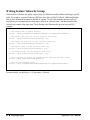
In addition, the DALSA Log Viewer utility program, included with Sapera LT, provides an easy way
to view error messages. It includes a list box that stores these messages as soon as the errors happen.
Available options allow you to modify the different fields for display.
42 • Introducing the Sapera LT API
Sapera LT User's Manual
During development, it is recommended to start the Log Viewer before your application and then let it
run so it can be referred to any time a detailed error description is required. However, errors are also
stored by a low-level service (running in the background), even if the utility is not running. Therefore,
it is possible to run it only when a problem occurs with your application.
Capabilities and Parameters
Sapera++ already includes all the functionality necessary for most Sapera LT applications. However,
some features are only available in the Standard API. Capabilities and parameters are of particular
interest in this case. Together they define a resource's ability and current state.
See the Sapera Basic Modules Reference Manual for a description of all capabilities and parameters,
and their possible values.
What is a Capability?
A capability, as its name implies, is a value or set of values that describe what a resource can do.
Capabilities are used to determine the possible valid values that can be applied to a resource's
parameters. They are read-only.
A capability can be obtained from a resource by using the GetCapability method in the corresponding
class. See the Sapera++ Programmer’s Manual for details
What is a Parameter?
A parameter describes a current characteristic of a resource. It can be read/write or read-only.
A parameter for a resource can be obtained or set by using the GetParameter and SetParameter
methods in the corresponding class. See the Sapera++ Programmer’s Manual for details.
Sapera LT User's Manual
Introducing the Sapera LT API • 43
44 • Introducing the Sapera LT API
Sapera LT User's Manual
Acquiring Images
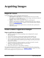
Required Classes
You need three Sapera++ classes to initiate the acquisition process:
• SapAcquisition or SapAcqDevice: Use the SapAcquisition class if you are using a
frame grabber; use the SapAcqDevice class if you are using a camera directly connected
to your PC, such as a GigE or DCAM camera.
• SapBuffer: Used to store the acquired data. Should be created using the
SapBuffer::TypeContiguous or SapBuffer::TypeScatterGather buffer type to enable the
transfer (see "Working with Buffers" on page 61 for more information about contiguous
memory and scatter-gather).
• SapTransfer: Used to link the acquisition device to the buffer and to synchronize the
acquisition operations.
Frame-Grabber Acquisition Example
Steps to perform an acquisition
•
•
•
•
•
•
•
Specify the acquisition device and corresponding camera configuration file, using the
SapAcquisition class.
Create a buffer in memory to store the acquired image, using the SapBuffer class.
Allocate a view object to display the image, using the SapView class, if required.
Allocate a transfer object to link the acquisition to the image buffer, using the SapTransfer
class. A transfer callback function should be registered if images need to be processed and
displayed while grabbing.
Allocate the resources for all objects (acquisition, view, buffer, and transfer), using the
respective Create function of the class used to create the objects.
Grab images, using the SapTransfer class.
Destroy all created resources, when grabbing is completed.
This sample code demonstrates how to grab a live image into a buffer allocated in system memory
using the X64-CL board as an acquisition device. See "Appendix A: Support" on page 67 for a list of
DALSA boards equipped with an acquisition section.
Sapera LT User's Manual
Acquiring Images • 45
As shown in the example, acquiring an image requires one file (the CCF file) to configure the
acquisition hardware. It defines both the characteristics of the camera and how it will be used with the
acquisition hardware. Refer to the section “Using the CamExpert Tool” on page 11 for a discussion on
how to generate this file. Resource parameters can also be accessed individually.
Once the acquisition module is initialized using the CCF file, a compatible buffer may be created using
settings taken directly from the acquisition.
Before initiating the actual transfer, you must create a transfer object to link the acquisition and the
buffer objects. Furthermore, when stopping a transfer, you must call the SapTransfer::Wait method to
wait for the transfer process to terminate completely.
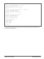
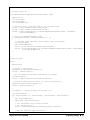
// Transfer callback function is called each time a complete frame is transferred
//
void XferCallback(SapXferCallbackInfo *pInfo)
{
// Display the last transferred frame
SapView *pView = (SapView *) pInfo->GetContext();
pView->Show();
}
// Example program
//
main()
{
// Allocate acquisition object
SapAcquisition *pAcq =
new SapAcquisition(SapLocation “X64-CL_1”, 0), “MyCamera.ccf”);
// Allocate buffer object, taking settings directly from the acquisition
SapBuffer *pBuffer = new SapBuffer(1, pAcq);
// Allocate view object, images will be displayed directly on the desktop
SapView *pView = new SapView(pBuffer, SapHwndDesktop);
// Allocate transfer object to link acquisition and buffer
SapTransfer *pTransfer = new SapTransfer(XferCallback, pView);
pTransfer->AddPair(SapXferPair(pAcq, pBuffer));
// Create resources for all objects
BOOL success = pAcq->Create();
success = pBuffer->Create();
success = pView->Create();
success = pTransfer->Create();
46 • Acquiring Images
Sapera LT User's Manual
// Start a continuous transfer (live grab)
success = pTransfer->Grab();
printf("Press any key to stop grab\n");
getch();
// Stop the transfer and wait (timeout = 5 seconds)
success = pTransfer->Freeze();
success = pTransfer->Wait(5000);
printf("Press any key to terminate\n");
getch();
// Release resources for all objects
success = pTransfer->Destroy();
success = pView->Destroy();
success = pBuffer->Destroy();
success = pAcq->Destroy();
// Free all objects
delete pTransfer;
delete pView;
delete pBuffer;
delete pAcq;
}
return 0;
For more details, see the Sapera++ Programmer’s Manual and the source code for the demos and
examples included with Sapera LT.
Sapera LT User's Manual
Acquiring Images • 47
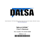
Modifying the Frame-Grabber Parameters
Modifying Parameters Individually
Acquisition parameters can be modified individually by using the SapAcquisition::SetParameter
method. When a new parameter value is requested, that value is verified against the current state of the
acquisition module and the acquisition module capabilities. If the modification request is denied
because the parameter is dependent on other parameters, then all the parameters in question must be
modified by group.
// Allocate and create resources for acquisition object
SapAcquisition *pAcq =
new SapAcquisition(SapLocation(“X64-CL_1”, 0), “MyCamera.ccf”);
BOOL success = pAcq->Create();
// Try changing the sync source to Composite Sync
success = pAcq->SetParameter(CORACQ_PRM_SYNC, CORACQ_VAL_SYNC_COMP_SYNC);
// Release resources for acquisition object, and free it
success = pAcq->Destroy();
delete pAcq;
For more details, see the Sapera++ Programmer’s Manual and the Sapera Basic Modules Reference
Manual.
Triggered Acquisition Example
The following code sample demonstrates how to set individual parameters, using the SapAcquisition
class SetParameter function, to perform a triggered acquisition (area scan camera). These parameters
are set after creating your acquisition object and resources, and before grabbing.
pAcq->SetParameter(CORACQ_PRM_EXT_TRIGGER_LEVEL, CORACQ_VAL_LEVEL_TTL);
pAcq->SetParameter(CORACQ_PRM_EXT_TRIGGER_ENABLE, CORACQ_VAL_EXT_TRIGGER_ON);
pAcq->SetParameter(CORACQ_PRM_EXT_TRIGGER_DETECTION, CORACQ_VAL_RISING_EDGE);
48 • Acquiring Images
Sapera LT User's Manual
Modifying Parameters by Group
Acquisition parameters can be modified by groups using the optional updateNow parameter to the
SapAcquisition::SetParameter method. When a new set of values is written, all modified parameters
are verified against the given state and capabilities of the acquisition object.
// Allocate and create resources for acquisition object
SapAcquisition *pAcq =
new SapAcquisition(SapLocation(“X64-CL_1”, 0), “MyCamera.ccf”);
BOOL success = pAcq->Create();
// Try changing the cropping and scaling parameters
success = pAcq->SetParameter(CORACQ_PRM_CROP_WIDTH, 640, FALSE);
success = pAcq->SetParameter(CORACQ_PRM_CROP_HEIGTH, 480, FALSE);
success = pAcq->SetParameter(CORACQ_PRM_SCALE_HORZ, 640, FALSE);
success = pAcq->SetParameter(CORACQ_PRM_SCALE_VERT, 480, TRUE);
// Release resources for acquisition object, and free it
success = pAcq->Destroy();
delete pAcq;
For more details, see the Sapera++ Programmer’s Manual and the Sapera Basic Modules Reference
Manual.
Sapera LT User's Manual
Acquiring Images • 49
Using an Input Lookup Table
When you call the Create method for a SapAcquisition object, an internal lookup table object (SapLut)
is automatically created inside the object, if the acquisition hardware supports lookup tables.
You may then retrieve it using the SapAcquisition::GetLut method, manipulate it using the methods in
the SapLut Class, and reprogram it using the SapAcquisition::ApplyLut method.
The internal SapLut object is automatically destroyed when you call the SapAcquisition::Destroy
method.
// Allocate and create resources for acquisition object
SapAcquisition pAcq =
new SapAcquisition(SapLocation(“X64-CL_1”, 0), “MyCamera.ccf”);
BOOL success = pAcq->Create();
// Try changing the acquisition lookup table using a custom mapping
// The GetLut method returns NULL if there is no acquisition LUT
SapLut pLut = pAcq->GetLut();
// Allocate working memory for the new lookup table data
char *pNewData = new char[pLut->GetTotalSize()];
// Fill contents of data buffer …
// Write new data to lookup table
pLut->Write(0, pNewData, pLut->GetTotalSize());
// Program the acquisition hardware with the new LUT data
pAcq->ApplyLut();
// Free working memory
delete [] pNewData;
// Release resources for acquisition object, and free it
success = pAcq->Destroy();
delete pAcq;
50 • Acquiring Images
Sapera LT User's Manual
Camera Acquisition Example
The camera acquisition example demonstrates how to grab a live image into a buffer allocated within
system memory using the Genie M640 camera as an acquisition device.
Acquiring an image can be performed either by using the camera default settings (feature values stored
in the camera) or by loading a configuration file. The configuration file can be generated using
CamExpert.
After the SapAcqDevice class is initialized (with or without using a configuration file), certain
parameters are retrieved from it (acquisition width, height, and format) to create a compatible buffer.
Before starting the transfer, you must create a transfer path between the SapAcqDevice class and the
SapBuffer class using one of the SapTransfer’s derived classes (SapAcqDeviceToBuf in this case).
Furthermore, when requesting a transfer stop, you must call SapTransfer::Wait to wait for the transfer
process to terminate completely.
// Transfer callback function is called each time a complete frame is transferred
//
void XferCallback(SapXferCallbackInfo *pInfo)
{
// Display the last transferred frame
SapView *pView = (SapView *) pInfo->GetContext();
pView->Show();
}
// Example program
//
main()
{
// Allocate acquisition object
SapAcqDevice *pAcq =
new SapAcqDevice("Genie_M640_1", FALSE); // uses camera default settings
//new SapAcqDevice("Genie_M640", "MyCamera.ccf"); // loads configuration file
// Allocate buffer object, taking settings directly from the acquisition
SapBuffer *pBuffer = new SapBuffer(1, pAcq);
// Allocate view object to display in an internally created window
SapView *pView = new SapView(pBuffer, (HWND)-1);
// Allocate transfer object to link acquisition and buffer
SapAcqDeviceToBuf *pTransfer =
new SapAcqDeviceToBuf(pAcq, pBuffer, XferCallback, pView);
// Create resources for all objects
BOOL success = pAcq->Create();
success = pBuffer->Create();
success = pView->Create();
success = pTransfer->Create();
Sapera LT User's Manual
Acquiring Images • 51
// Start a continuous transfer (live grab)
success = pTransfer->Grab();
printf("Press any key to stop grab\n");
getch();
// Stop the transfer and wait (timeout = 5 seconds)
success = pTransfer->Freeze();
success = pTransfer->Wait(5000);
printf("Press any key to terminate\n");
getch();
// Release resources for all objects
success = pTransfer->Destroy();
success = pView->Destroy();
success = pBuffer->Destroy();
success = pAcq->Destroy();
// Free all objects
delete pTransfer;
delete pView;
delete pBuffer;
delete pAcq;
}
return 0;
Modifying the Camera Features
The following section describes how to modify camera features individually or by group.
Accessing Feature Information and Values
The following example shows how features of the camera can be accessed. Information such as type,
range and access mode can be retrieved for each supported feature. The SapAcqDevice class also
allows modifying the feature values by directly writing to the camera. In some circumstances, a set of
feature values are tightly coupled together and must be written to the camera at the same time. The
next section shows how to proceed in such a case.
52 • Acquiring Images
Sapera LT User's Manual
//
// Callback Function
//
void CameraCallback(SapAcqDeviceCallbackInfo* pInfo)
{
BOOL status;
int eventCount;
int eventIndex;
char eventName[64];
// Retrieve count, index and name of the received event
status = pInfo->GetEventCount(&eventCount);
status = pInfo->GetEventIndex(&eventIndex);
status = pInfo->GetAcqDevice()->GetEventNameByIndex(eventIndex, eventName,
sizeof(eventName));
}
// Check for "FeatureChanged" event
if (strcmp(eventName, "FeatureChanged") == 0)
{
// Retrieve index and name of the feature that has changed
int featureIndex;
char featureName[64];
status = pInfo->GetFeatureIndex(&featureIndex);
status = pInfo->GetAcqDevice()->GetFeatureNameByIndex(featureIndex, featureName,
sizeof(featureName));
}
//
// Main Program
//
main()
{
BOOL status;
// Create a camera object
SapAcqDevice camera("Genie_M640_1");
status = camera.Create();
// Get the number of features provided by the camera
int featureCount;
status = camera.GetFeatureCount(&featureCount);
// Create an empty feature object (to receive information)
SapFeature feature("Genie_M640_1");
status = feature.Create();
//
// Example 1 : Browse through the feature list
//
int featureIndex;
for (featureIndex = 0; featureIndex < featureCount; featureIndex++)
{
char featureName[64];
SapFeature::Type featureType;
// Get information from current feature
// Get feature object
status = camera.GetFeatureInfo(featureIndex, &feature);
// Extract name and type from object
Sapera LT User's Manual
Acquiring Images • 53
status = feature.GetName(featureName, sizeof(featureName));
status = feature.GetType(&featureType);
// Get/set value from/to current feature
switch (featureType)
{
// Feature is a 64-bit integer
case SapFeature::TypeInt64:
{
UINT64 value;
status = camera.GetFeatureValue(featureIndex, &value);
value += 10;
status = camera.SetFeatureValue(featureIndex, value);
}
break;
// Feature is a boolean
case SapFeature::TypeBool:
{
BOOL value;
status = camera.GetFeatureValue(featureIndex, &value);
value = !value;
status = camera.SetFeatureValue(featureIndex, value);
}
break;
}
}
// Other feature types
// ...
//
// Example 2 : Access specific feature (integer example)
//
// Get feature object
status = camera.GetFeatureInfo("Gain", &feature);
// Extract minimum, maximum and increment values
UINT32 min, max, inc;
status = feature.GetMin(&min);
status = feature.GetMax(&max);
status = feature.GetInc(&inc);
// Read, modify and write value
UINT32 value;
status = camera.GetFeatureValue("Gain", &value);
value += 10;
status = camera.SetFeatureValue("Gain", value);
//
// Example 3 : Access specific feature (enumeration example)
//
// Get feature object
status = camera.GetFeatureInfo("GainMode", &feature);
// Get number of items in enumeration
int enumCount;
status = feature.GetEnumCount(&enumCount);
int enumIndex, enumValue;
char enumStr[64];
for (enumIndex = 0; enumIndex < enumCount; enumIndex++)
54 • Acquiring Images
Sapera LT User's Manual
{
}
// Get item string and value
status = feature.GetEnumString(enumIndex, enumStr, sizeof(enumStr));
status = feature.GetEnumValue(enumIndex, &enumValue);
// Read a value and get its associated string
status = camera.GetFeatureValue("GainMode", &enumValue);
status = feature.GetEnumStringFromValue(enumValue, enumStr, sizeof(enumStr));
// Write a value corresponding to known string
status = feature.GetEnumValueFromString("GainModeOnePush", &enumValue);
status = camera.SetFeatureValue("GainMode", enumValue);
//
// Example 4 : Access specific feature (LUT example)
//
// Select a LUT and retrieve its size and format
UINT32 lutIndex = 0, lutNEntries, lutFormat;
status = camera.SetFeatureValue("LUT_Index", lutIndex);
status = camera.GetFeatureValue("LUT_NEntries", &lutNEntries);
status = camera.GetFeatureValue("LUT_Format", &lutFormat);
// Create and generate a compatible software LUT
SapLut lut(lutNEntries, lutFormat);
status = lut.Create();
status = lut.Reverse();
// Write LUT values to camera
status = camera.SetFeatureValue("LUT_Values", &lut);
//
// Example 5 : Callback management
//
// Browse event list
int numEvents;
status = camera.GetEventCount(&numEvents);
int eventIndex;
for (eventIndex = 0; eventIndex < numEvents; eventIndex++)
{
char eventName[64];
status = camera.GetEventNameByIndex(eventIndex, eventName, sizeof(eventName));
}
// Register event by name
status = camera.RegisterCallback("FeatureChanged", CameraCallback, NULL);
// Modified a feature (Will trigger callback function)
status = camera.SetFeatureValue("Gain", 150);
}
// Unregister event by name
status = camera.UnregisterCallback("FeatureChanged");
Sapera LT User's Manual
Acquiring Images • 55
Writing Feature Values by Group
When a series of features are tightly coupled, they are difficult to modify without following a specific
order. For example, a region-of-interest (ROI) has four values (OffsetX, OffsetY, Width and Height)
that are inter-dependent and must be defined as a group. To solve this problem, the SapAcqDevice
class allows you to temporarily set the feature values in an “internal cache” and then download the
values to the camera at the same time. The following code illustrates this process using an ROI
example.
…
// Set manual mode to update features
success = pAcq->SetUpdateFeatureMode(SapAcqDevice::UpdateFeatureManual);
// Set buffer left position (in the internal cache only)
success = pAcq->SetFeatureValue("OffsetX", 50);
// Set buffer top position (in the internal cache only)
success = pAcq->SetFeatureValue("OffsetY", 50);
// Set buffer width (in the internal cache only)
success = pAcq->SetFeatureValue("Width", 300);
// Set buffer height (in the internal cache only)
success = pAcq->SetFeatureValue("Height", 300);
// Write features to device (by reading values from the internal cache)
success = pAcq->UpdateFeaturesToDevice();
// Set back the automatic mode
success = pAcq->SetUpdateFeatureMode(SapAcqDevice::UpdateFeatureAuto);
…
For more details, see the Sapera++ Programmer’s Manual.
56 • Acquiring Images
Sapera LT User's Manual
Displaying Images
Required Classes
The following three Sapera++ classes are required to initiate a display process:
•
SapDisplay: Manages the actual resources on the hardware display device.
•
SapBuffer: Contains the data to display. Several type options may be chosen when allocating
the buffer to be compatible with the different display modes (see "Working with Buffers" on
page 61 for more information about these options).
•
SapView: Links the display to the buffer and synchronizes the display operations.
Display Example
The example below illustrates how to display an image contained within a system buffer on the
computer VGA card. The buffer is transferred to the Windows Desktop using the DIB mode
(automatically detected by the SapView Class). When using this mode, a Windows DeviceIndependent Bitmap (DIB) is first created before being sent to VGA memory.
// Allocate and create a 640x480x8 buffer object
SapBuffer *pBuffer = new SapBuffer(1, 640, 480, SapFormatMono8);
BOOL success = pBuffer->Create();
// Allocate and create view object, images will be displayed directly on the desktop
SapView *pView = new SapView(pBuffer, SapHwndDesktop);
success = pView->Create();
// Display the image on the desktop
pView->Show();
// Release resources for all objects
success = pView->Destroy();
success = pBuffer->Destroy();
// Free all objects
delete pView;
delete pBuffer;
For more details, see the Sapera++ Programmer’s Manual.
Sapera LT User's Manual
Displaying Images • 57
Displaying in a Windows Application
The SapView Class includes the three methods OnPaint, OnMove, and OnSize. When your Windows
application is based on MFC, you should call these from within the OnPaint, OnMove, and OnSize
handlers in your application program. This ensures that Sapera++ is aware about the changes to the
display area.
However, these methods often do not offer, especially for scroll bars, a sufficient level of management
following changes to the display area. So it is recommended that you use the methods with the same
names in the CImageWnd Class instead. Note that this class is part of the GUI classes.
Here is a partial listing of a dialog-based Windows application using the Visual C++'s MFC library:
// Declarations from class header file
SapBuffer *m_pBuffer;
SapView *m_pView;
CImageWnd *m_ImageWnd;
// End declarations from class header file
CSaperaAppDlg::CSaperaAppDlg()
{
m_pBuffer = NULL;
m_pView = NULL;
m_pImageWnd = NULL;
}
// Other initialization
...
BOOL CSaperaAppDlg::OnInitDialog()
{
// Call default handler
CDialog::OnInitDialog();
// Other initialization
...
// Allocate and create a 640x480x8 buffer object
*m_pBuffer = new SapBuffer(1, 640, 480, SapFormatMono8);
BOOL success = m_pBuffer->Create();
// Allocate and create view object, images will be displayed in the MFC CWnd
// object identified by m_ViewWnd
m_pView = new SapView(m_pBuffer, m_ViewWnd.GetSafeHwnd());
success = m_pView->Create();
// Create image window object. The m_HorizontalScr and m_VerticalScr arguments
// are MFC CscrollBar objects representing the scroll bars.
m_pImageWnd = new CImageWnd(m_pView, &m_ViewWnd,
&m_HorizontalScr, &m_VerticalScr, this);
}
return TRUE;
58 • Displaying Images
Sapera LT User's Manual
CSaperaAppDlg::OnDestroy()
{
// Release resources for all objects
BOOL success = m_pView->Destroy();
success = m_pBuffer->Destroy();
}
// Free all objects
delete m_pImageWnd
delete m_pView;
delete m_pBuffer;
void CSaperaAppDlg::OnPaint()
{
if (IsIconic())
{
...
}
else
{
// Call the default handler to paint a background
CDialog::OnPaint();
}
}
// Display last acquired image
m_pImageWnd->OnPaint();
void CSaperaAppDlg::OnSize(UINT nType, int cx, int cy)
{
// Call default handler
CDialog::OnSize(nType, cx, cy);
}
// Make appropriate adjustment in image window
m_pImageWnd->OnSize();
void CSaperaAppDlg::OnMove(int x, int y)
{
// Call default handler
CDialog::OnMove(x, y);
}
// Make appropriate adjustment in image window
m_pImageWnd->OnMove();
For more details, see the Sapera++ Programmer’s Manual and the source code for the demos and
examples included with Sapera LT.
Sapera LT User's Manual
Displaying Images • 59
60 • Displaying Images
Sapera LT User's Manual
Working with Buffers
Root and Child Buffers
A buffer object is created in one of two ways: either as a root SapBuffer object (with no parent) or as a
child SapBufferRoi object (with a parent). The parent of the child may also be a child itself, which
allows you to build a buffer hierarchy with no restriction on the number of levels. A SapBuffer object
can have more than one child SapBufferRoi object.
A SapBufferRoi object shares the same memory space as its parent, and it defines an adjustable
rectangular region of interest. A child may be used by acquisition to reduce bandwidth requirements,
or by a processing function in order to process a specific region.
The example below illustrates how to create a parent buffer with two children.
Note: SapBufferRoi objects must be destroyed before their parent.
// Allocate and create a 640x480x8 buffer object
SapBuffer *pBuffer = new SapBuffer(1, 640, 480, SapFormatMono8);
BOOL success = pBuffer->Create();
// Allocate and create a 320x240 child in the upper-left corner
SapBufferRoi *pChild1 = new SapBufferRoi(pBuffer, 0, 0, 320, 240)
success = pChild1->Create();
// Allocate and create a 320x240 child in the upper-right corner
SapBufferRoi *pChild2 = new SapBufferRoi(pBuffer, 320, 0, 320, 240)
success = pChild2->Create();
// Use buffers
...
// Release resources for all objects
success = pBuffer->Destroy();
success = pChild1->Destroy();
success = pChild2->Destroy();
// Free all objects
delete pBuffer;
delete pChild1;
delete pChild2;
Sapera LT User's Manual
Working with Buffers • 61
You may modify the origin and dimensions of the region of interest for a child buffer object before
calling its Create method. The following example demonstrates this concept.
// Swap left and right children, and make their height the same as the parent
success = pChild1->SetRoi(320, 0, 320, 480);
success = pChild2->SetRoi(0, 0, 320, 480);
Buffer Types
You may create a SapBuffer object using one of many predefined types. This has an effect on how the
actual buffer resources are allocated, and on how the object may be used with other classes, such as
SapTransfer and SapView.
Contiguous Memory Buffers (SapBuffer::TypeContiguous)
Buffers are allocated in Sapera LT Contiguous Memory, which is one large chunk of non-pageable
and non-moveable memory reserved by Sapera LT at boot time. Buffer data is thus contained in a
single memory block (not segmented). These buffers may be used as source and destination for
transfer resources.
Scatter-Gather Memory Buffers (SapBuffer::TypeScatterGather)
Buffers are allocated in noncontiguous memory (paged pool). Pages are locked in physical memory so
that a scatter-gather list may be built. This allows allocation of very large buffers to be used as source
and destination for transfer resources. The maximum amount of memory that may be allocated
depends on available memory, the operating system, and the application(s) used. If the amount of
system memory exceeds four GB, Sapera LT automatically uses TypeScatterGatherPhysical instead.
Virtual Buffers (SapBuffer::TypeVirtual)
Similar to TypeScatterGather, except that the memory pages are not locked. This allows allocation of
very large buffers, but they cannot be used as source or destination for transfer resources.
Offscreen Buffers (SapBuffer::TypeOffscreen)
Buffers are allocated in system memory. SapView objects created using these buffers may use display
adapter hardware to copy from the buffer to video memory. System memory offscreen buffers may be
created using any pixel format, but calling the SapView::Show method will take longer to execute if
the display hardware does not efficiently support its pixel format.
OffScreen Buffers in Video Memory (SapBuffer::TypeOffscreenVideo)
Buffers are allocated in offscreen video memory. SapView objects created using these buffers use
display adapter hardware to perform a fast copy in video memory. These buffers are typically used
when a graphical element is reused for several consecutive frames without modification. In this case, it
is more efficient to keep this element in video memory and use display hardware capabilities.
Overlay Buffers (SapBuffer::TypeOverlay)
62 • Working with Buffers
Sapera LT User's Manual
Buffers are allocated in video memory. Once you create SapView objects using these buffers and call
their Show method one time, the display adapter overlay hardware will keep updating the display with
the buffer contents with no additional calls The pixel format of overlay buffers must be supported by
the display hardware. Typically, overlay buffers support more pixel formats (like YUV) than offscreen
buffers. Also, color keying is supported for overlays. SapView Class determines the behavior of the
overlay regarding key colors.
Dummy Buffers (SapBuffer::TypeDummy)
Dummy buffers do not have any data memory. They may be used as placeholders by transfer resources
when there is no physical data transfer.
Physical Memory Buffers (SapBuffer::TypeUnmapped)
Buffers are allocated as a series of non-contiguous chunks of physical memory. You may not access
their data until they have been mapped to virtual memory addresses using the SapBuffer::GetAddress
method. This type of buffer is useful if the total amount of needed buffer data exceeds the amount of
available virtual memory addresses (2 GB under Windows). To avoid a shortage of virtual memory
addresses, use the SapBuffer::ReleaseAddress method as soon as you are done accessing their data.
Note that you cannot acquire images into these buffers.
Physical Scatter-Gather Memory Buffers (SapBuffer::TypeScatterGatherUnmapped)
These buffers are similar to TypePhysical, except that you can acquire images into them.
Sapera LT User's Manual
Working with Buffers • 63
Reading and Writing a Buffer
The simplest way to read or write data to a buffer resource is by accessing it element by element. The
ReadElement and WriteElement methods fulfill this purpose. The following demonstrates how to
access data in an 8-bit monochrome SapBuffer object.
// Allocate and create a 640x480x8 buffer object
SapBuffer *pBuffer = new SapBuffer(1, 640, 480, SapFormatMono8);
BOOL success = pBuffer->Create();
// Write a constant value in the buffer. SapDataMono is a Sapera++ class
// that encapsulates a Standard API monochrome data type.
success = pBuffer->WriteElement(100, 200, SapDataMono(128));
// Read back the value
SapDataMono data;
success = pBuffer->ReadElement(100, 200, &data);
// Release and free resources for SapBuffer object
success = pBuffer->Destroy();
delete pBuffer;
Accessing buffer data in this way is quite straightforward, but, unfortunately, it considerably slows
down access time. Alternately, you can access data by reading/writing an array of elements with only
one function call through the Read and Write methods. Here is a sample of their usage.
// Allocate and create a 640x480x8 buffer object
SapBuffer *pBuffer = new SapBuffer(1, 640, 480, SapFormatMono8);
BOOL success = pBuffer->Create();
// Create an array large enough to hold all buffer data
int size = 640 * 480 * sizeof(BYTE);
BYTE *dataBuf = new BYTE [size];
// Fill array with some values
...
// Write array to buffer resource
success = pBuffer->Write(0, size, dataBuf);
// Read back buffer data
success = pBuffer->Read(0, size, dataBuf);
// Release and free resources for SapBuffer object
success = pBuffer->Destroy();
delete pBuffer;
// Free the data buffer
delete dataBuf;
Although this is faster than the previous method, performance is still an issue because of the data
copying operations involved.
64 • Working with Buffers
Sapera LT User's Manual
The fastest way to access buffer data is to obtain direct access through a pointer. The GetAddress and
ReleaseAddress methods initiate and end direct data access, respectively . The drawback of this
method is that you need to know the buffer dimensions, format, and pitch in order to correctly access
the data. The following code illustrates this.
// Allocate and create a 640x480 RGB 5-6-5 buffer object in offscreen video memory
SapBuffer *pBuffer =
new SapBuffer(1, 640, 480, SapFormatRGB565, SapBuffer::TypeOffscreenVideo);
BOOL success = pBuffer->Create();
// Get the buffer pitch in bytes
int pitch = pBuffer->GetPitch();
// Get the buffer data address
BYTE *pData;
success = pBuffer->GetAddress(&pData);
// Access the buffer data
for (int lineNum = 0; lineNum < 480; lineNum++)
{
WORD *pLine = (WORD *) (pData + lineNum * pitch);
for (pixelNum = 0; pixelNum < 640; pixelNum++)
{
// Process the current line
}
}
// End direct data access (pointer will then be invalid)
success = pBuffer->ReleaseAddress(pData);
// Release and free resources for SapBuffer object
success = pBuffer->Destroy();
delete pBuffer;
For more information on buffer data access functionality, see the Sapera++ Programmer’s Manual.
Sapera LT User's Manual
Working with Buffers • 65
66 • Working with Buffers
Sapera LT User's Manual
Appendix A: Support
Supported Operating Systems
•
•
Microsoft Windows® 2000
Windows XP®
Supported DALSA Devices
This section lists the current set of DALSA devices supported under Sapera LT. Consult the DALSA
web site for product descriptions. Consult the user’s manual for each device for a detailed description
of the supported features.
Frame-Grabbers
• Bandit-II Series
• Bandit-3 Series
• PC2 Series
• Viper Series
• X64 Series
Processing Boards
• Anaconda Series
Cameras
•
Genie Series
Sapera LT User's Manual
Appendix A: Support • 67
System Support
The Sapera LT system server represents Sapera LT functionality running on the Host processor when
no DALSA device is present. This section describes the resources available for this server.
Servers and Resources
Servers
Resources
Name
Description
Type
Index: Name
Description
System
System
server
Display
0: Default display
Computer video card
68 • Appendix A: Support
Graphic
0: Default graphic
Computer processor
File
N/A
N/A
Buffer
N/A
N/A
Lut
N/A
N/A
View
N/A
N/A
Sapera LT User's Manual
Appendix B: Other Tools
DirectDraw Capabilities Detection Tool
Use the DirectDraw Capabilities Detection tool to determine what “DirectDraw” capabilities a VGA
card supports. The resulting information can be used to help determine the application View mode to
be used.
To run this program, select DALSA DirectDraw Capabilities Detection in the Tools folder of the
Sapera LT menu. Click on the button Start Test. The program runs a series of tests to ascertain if
your VGA card supports “Overlay” and “Offscreen” modes for the different display formats. The
following screen shot illustrates an example of the outcome of the test.
Sapera LT User's Manual
Appendix B: Other Tools • 69
Font Generator Tool
The CorFont.exe tool program included with Sapera LT provides an easy way to create new fonts that
can then be used by the Graphic module.
You are allowed to modify the font attributes by clicking on the Font button. The preview window
shows you what the font will look like. The font can then be saved as a Text File (.h) or a Binary File
(.cfn). The font, if saved as a text file, can be included directly into your C/C++ source code while the
font saved as a binary file must always be loaded from the disk. See the “CorGraphicSetFont” function
and “Graphic Font File Format” description in the Sapera Basic Modules Reference Manual for more
information about using fonts.
DALSA Diagnostic tool
Overview:
The DALSA Diagnostic Tool is a troubleshooting aid for Sapera LT and device driver installations. It
can generate reports for all supported DALSA devices installed in the system. It does not provide
reports for old device driver releases.
This tool generates a system diagnostic report as an XML file. This file can be sent to DALSA
technical support when assistance is required.
70 • Appendix B: Other Tools
Sapera LT User's Manual
Diagnostic Tool Features:
•
Supported by all new DALSA device drivers.
•
Creates an XML diagnostic report file listing relevant files and system registry entries:
•
o
Validity status after the diagnostic process for each item
o
Path where each file should be found
o
File name
o
File version (if available)
o
File creation date
o
Date of latest file modification
o
File size
o
File author (company name)
o
For registry keys: path, name, and value)
View information in XML file with Internet Explorer.
Usage Guide:
When the diagnostic tool is run, the set of installed and supported DALSA device drivers is listed
along with the current Sapera LT installation.
Four items are listed for each:
ENV_NAME:
Environment variable name related to the product.
NAME:
Name of the product.
FILE:
XML reference file name installed with the product.
PATH:
Path where the XML reference file is installed.
You may generate a diagnostic report on either a single product or all installed products.
Validate All:
• Click Validate All to generate a diagnostic file (xml extension) containing an analysis of all
listed products.
•
At the end of diagnostic process, click the Display Results button to view the diagnostic file.
Validate:
• Click Validate to generate a diagnostic file (xml extension) containing an analysis of the
currently selected product.
•
At the end of diagnostic process, click the Display Results button to view the diagnostic file.
Sapera LT User's Manual
Appendix B: Other Tools • 71
72 • Appendix B: Other Tools
Sapera LT User's Manual
Report File Directory:
Before running either validate options, the report file name or directory can be changed from the
default.
Sample Diagnostic XML file:
Important features of the diagnostic report are:
• Click Contact Online Technical Support to open a new Internet Explorer page that links to
the "Contact Technical Support" page of the DALSA website. Follow the steps to request support
and attach the diagnostic XML file.
• A summary lists the version numbers for installed products and gives separate counts for items
with "Valid" and "Not Found" status.
•
Click on any product name to jump directly to a detailed listing of this product.
Sapera LT User's Manual
Appendix B: Other Tools • 73
74 • Appendix B: Other Tools
Sapera LT User's Manual
Appendix C: Sapera LT
Runtimes
Introduction
Once your application is ready to be delivered, you may need to create a procedure that will install the
appropriate component to the target system. The following section details the tasks that your
installation program needs to perform.
The appropriate device driver must be installed along with the installation of the Sapera LT runtimes.
This topic is further discussed in this section.
Installing Sapera LT Runtimes and Sapera LT
Compatible Drivers
The Sapera LT Installation Program automatically handles the task of copying files and making
Windows Registry changes, as dictated by your selection of Sapera LT (full development or runtime
components only) and the selected device drivers. When integrating Sapera LT and the Sapera LT
device driver installations into your system, DALSA suggests that the Sapera LT Install Program be
invoked within your own software installation program.
The Sapera LT installation is supplied in two forms: Developer and Runtime installations. The
Developer installation is accessible from the Sapera LT CD browser and contains all Sapera LT
components (demos, tools, documentation, and the Sapera LT runtimes). The Runtime version
contains only the components required to execute your application. It is recommended that you install
the Runtime components only on systems not used for development. You will find the Sapera LT
installation in the Sapera LT\Runtime directory on the Sapera LT CD.
Unlike the Sapera LT installation, there is only one way to perform Sapera LT driver installations. A
driver installation contains the device driver, the device’s user’s manual and, in some cases, some
device specific demos.
Usually, the installation files are contained in one directory (for example, \Disk1). Sometimes,
however, they are packaged in several directories (\Disk1, \Disk2, ….). In this case, you may include
the installation files on your CD using this same directory structure. The subdivided directories can
also be merged into one single directory; however, any sub-directories that the install directories
Sapera LT User's Manual
Appendix C: Sapera LT Runtimes • 75
(\Disk1, \Disk2…) have within must remain unchanged. Do not merge their content into the main
install directory.
For example this directory tree
when merged would become
DALSA Installers
Both Sapera LT and the driver installations share the same installer technology. As a result, the
following discussion applies to both.
Note: You must reboot after the installation of Sapera LT. However, to streamline the installation
process, you may install Sapera LT (without rebooting), the required device drivers and then reboot.
DALSA's installers can be started in two ways:
1.
Normal Mode
This is the interactive mode provided by default. It is initiated by invoking the setup.exe
program. The installation proceeds normally as if it was started from Windows Explorer
or the Windows command line.
2.
Silent Mode
This mode requires no user interaction. Any user input is provided through a “response”
file. Nothing is displayed by the installer.
Note: During driver installation, Windows Digital Signature and Logo Testing warnings can be safely
ignored.
76 • Appendix C: Sapera LT Runtimes
Sapera LT User's Manual
Silent Mode Installation
Silent Mode installation is recommended when integrating DALSA products into your software
installation. It provides a seamless installation with minimal effort.
Creating a response file
The “response” file is an “ASCII” file that is similar in content to Windows “INI” files. It can be
generated automatically by the installer when invoked as follows:
setup -r
The installer will create a “response” file (SETUP.ISS) in the Windows directory that will reflect the
choices you have made during the installation.
Running a Silent Mode Installation
The silent mode installation is started by invoking the installer as follows:
<path1>\setup -s –SMS -f1<path2>\setup.iss
The -F1 switch specifies the location of the response file.
Every file (including setup.exe) that belongs to disk 1 of the installation disk set must be in the same
directory. If there is more than one disk, you have two ways to organize your source disk:
1. Put all files into one directory
2. Store the content of each disk in a separate directory. The directory should be named
according to the following convention: \disk1, \disk2,…
Sapera LT User's Manual
Appendix C: Sapera LT Runtimes • 77
78 • Appendix C: Sapera LT Runtimes
Sapera LT User's Manual
DALSA Contact Information
Sales Information
Visit our web site:
http://www.imaging.com
Email:
[email protected]
International/Canada
DALSA
7075 Place Robert-Joncas
Suite 142
St. Laurent, Quebec, Canada
H4M 2Z2
Tel:
(514) 333-1301
Fax:
(514) 333-1388
USA
DALSA
Building 8, Floor 2
900 Middlesex Turnpike
Billerica, MA 01821
Tel:
Fax:
(978) 670-2000
(978) 670-2010
Sapera LT User's Manual
DALSA Contact Information • 79
Technical Support
Any support question or request can be submitted via our web site:
Technical support form via our web page:
Support requests for imaging product installations,
Support requests for imaging applications
http://www.imaging.com/support
Camera support information
http://www.imaging.com/camsearch
Product literature and driver updates
http://www.imaging.com/download
When encountering hardware or software problems, please have the following documents included in
your support request:
• The DALSA Diagnostic Tool XML report file
• The DALSA Log Viewer .txt file
• The PCI Diagnostic PciDump.txt file
• The DALSA Device Manager BoardInfo.txt file
Note, all these tools are available from the Windows start menu shortcut
Start•Programs•DALSA•Sapera LT•Tools.
80 • DALSA Contact Information
Sapera LT User's Manual
Glossary of Terms
ADC
Analog-to-digital converter.
Chroma
The color portion of the composite NTSC or PAL video signal. Luma is the black-and-white
portion of the signal. Often used interchangeably with Chrominance, although this is technically
incorrect.
CMYK
A color model in which all colors are composed of varying intensities of the primary subtractive
colors: Cyan, Magenta, Yellow, and black. This color model is often used in print processing.
Color Key
Color keying is a method used to decide the source of a display pixel on the screen. If the graphics
pixel on the VGA screen has the pixel value of the color key, then the corresponding pixel in the
designated buffer will be displayed; otherwise, the VGA screen’s pixel will be displayed.
Complex Parameter
A parameter with a size greater than a UINT32.
Composite Video
A single signal that includes both color video and timing information. NTSC and PAL are
composite video standards, while RGB is not.
Dead Pixel
A defective pixel that remains unlit on an LCD screen, monitor, camera charge-coupled device or
CMOS sensor.
Decimation
A process whereby pixels are dropped from digitized video waveforms for quick-and-easy image
scaling. If 100 pixels are produced by a waveform, but only 50 are stored or used, the video
waveform has been decimated by a factor of 2:1.
DLL
Dynamic Link Library. The supplied DLLs form the software interface between a Windows
application and the DALSA hardware device.
Sapera LT User's Manual
Glossary of Terms • 81
Element
A data unit within the buffer, which may or may not be a pixel.
Frame Buffer
A large unit of memory used to hold the image for display onscreen.
Grayscale
In image processing, the range of available brightness levels, displayed in shades of gray. In an 8bit system, the gray scale contains values from 0 to 255.
Host Memory
The Windows system's random-access memory. Typically refers to a frame buffer allocated in the
computer system’s memory.
Interlaced
The standard television method of raster scanning, in which the image is the product of two fields,
each of which is made up of the image's alternate lines (that is, one field is comprised of lines 1, 3,
5, and so forth, and the other is comprised of lines 2, 4, 6, and so forth).
Keying Color
The Windows color which is used as a switch to the frame buffer video. Wherever the keying
color is drawn, it is replaced with video from the buffer.
Lookup Table, LUT
In image processing, the segment of memory that stores values for point processes. Input pixel
values are those of the original image, while output values are those altered by the chosen point
process. An input lookup table destructively modifies the stored image data, whereas the output
lookup table simply receives the stored data and modifies it for output only.
Luma
The black-and-white portion of the composite NTSC or PAL video signal. Chroma is the color
portion of the signal. Often used interchangeable with Luminance, although this is technically
incorrect.
Monochrome
A video source with only one component, usually meant to refer to a black-and-white composite
signal. A monochrome composite video source has no chroma information.
Noninterlaced
Video scanning method, in which all the lines in the frame are scanned out sequentially. Used in
several different analog and digital video systems, including Progressive Scan analog cameras,
digital video cameras and computer monitors.
82 • Glossary of Terms
Sapera LT User's Manual
NTSC
National Television Standards Committee. Color TV standard used in used in North America,
Japan, and in several other jurisdictions. The interlaced video signal is composed of a total of 525
video lines at a frame rate of 30 Hz.
Paged Pool Memory
Regions located in operating system’s kernel space from which memory blocks can be allocated
and deallocated dynamically. A memory block allocated in the paged pool memory is segmented
into several pages physically separated from each other. A page is a contiguous block of memory
limited in size (for example, Windows NT allocates pages of 4KB).
PAL
Phase Alteration by Line. Color TV standard used in most of Europe and in several other
jurisdictions. The interlaced video signal is composed of a total of 625 video lines at a frame rate
of 25 Hz.
PCI
Peripheral Component Interconnect. The PCI local bus is a 32-bit high performance expansion
bus intended for interconnecting add-in boards, controllers, and processor/memory systems.
Pixel
A single picture element, the smallest individual digital video component The number of pixels
describes the number of digital samples taken of the analog video signal. The number of pixels per
video line by the number of active video lines describes the acquisition image resolution. The
binary size of each pixel (for example, 8 bits, 15 bits, 24 bits) defines the number of gray levels or
colors possible for each pixel.
Raster
The pattern of lines traced by rectilinear scanning in display systems.
RGB
Red, Green, Blue. Commonly used to refer to a non-composite video standard which uses these
three colors in combination to generate a color video image.
RS-170
The original United States standard for black and white television. Now commonly used to refer
to monochrome analog video signals.
Scaling
The act of changing the effective resolution of an image.
Sapera LT User's Manual
Glossary of Terms • 83
SECAM
Sequentiel Couleur avec Mémoire, a TV standard similar to PAL, in which the chroma is FM
modulated and the R’-Y and B’-Y signals are transmitted line sequentially. Used primarily in
France and Russia as well as in several other French-speaking and former Warsaw Pact countries.
Service
Functionality derived from a particular software program. For example, network services may
refer to programs that transmit data or provide conversion of data in a network.
Simple Parameter
A parameter with a size less than or equal to a UINT32.
Stride
The memory distance between two pixels that are viewed as vertically adjacent in the image.
S-Video
Separate video, also known as Y/C video, which supports separate luma (Y) and chroma (C)
video inputs and outputs. Often used interchangeably with S-VHS, which is technically incorrect.
Sync
The basic piece of information which tells a video display (TV or computer monitor) where to put
the picture. Horizontal sync, or HSYNC, controls the left-right dimension and vertical sync, or
VSYNC controls the top-to-bottom dimension.
Tearing
A display artifact caused by the fact that the video display will read frame buffer memory
asynchronously to the incoming video stream. Tearing is non-data destructive.
Video Input Conditioning , VIC
The act of modifying an analog video signal via bandwidth filtering or gain amplification.
Y/C
See S-Video.
YUV
A common color space used in composite video color systems. Y is the luma component while U
and V are the color difference components.
84 • Glossary of Terms
Sapera LT User's Manual
Index
contiguous memory, 10, 45, 62
contiguous memory buffers, 62
CorXferWait, 51
CVI, 11, 27
D
A
About Sapera LT, 3
acquisition device
camera, 51
acquisition parameters, 19
ActiveX, 5, 7, 15, 17, 31, 39
ActiveX Controls, 39
API, 3, 4, 31, 33, 39, 40, 41, 42, 43
area scan, 13, 28
ASCII file, 77
AVI, 16
DALSA installers normal mode, 76
DALSA installers silent mode, 76, 77
DALSA Log Viewer, 42
Data Classes, 35
demonstration programs, 7, 10, 12, 15, 47, 59
Developer Installations, 75
diagnostic tool, 7, 70, 71
DIB, 57
DirectDraw, 69
DirectDraw Capabilities Detection Tool, 69
DirectDrawTM, 6
DirectShow, 4
dummy buffers, 63
dynamic resource, 32
B
Basic Classes, 3, 24
Board Specific Classes, 3
Boolean, 42
Borland C++, 5
Borland C++ Builder, 14
Borland Delphi, 5, 17
Buffer Types, 62
C
C++ class library, 3
CAB, 3
CAM file, 27
Camera file, 19
CamExpert, 4, 12, 27, 28
capability definition, 43
CCA, 11, 27
CCF, 11, 12, 13, 27, 46
CD-ROM, 6
child buffer, 61
code samples, 14
color keying, 63
contiguous, 13
Sapera LT User's Manual
E
example programs, 7, 10, 12, 14, 15, 47, 59
F
fixed pattern noise (FPN), 16
flat field correction, 16
Font Generator Tool, 70
FPN, 16
G
GrabDemo, 12
GUI Classes, 3, 14, 24, 58
H
Hardware Independent Classes, 3
high-level C++ class library, 3
I
INI file, 77
Index • 85
input lookup table, 50
Installation Procedure, 6
International/Canada Sales Office, 79
Internet, 2
Internet Explorer, 71
L
linescan, 13, 29
low-level service, 43
M
Manager Classes, 3
master mode, 28
MFC, 3, 15, 16, 24, 58
Microsoft Visual C++, 14
Microsoft Visual Studio, 15
module, 32
N
NTSC, 11
O
offscreen buffers, 62
offScreen buffers in video memory, 62
overlay, 13
overlay buffers, 63
P
paged pool, 62
PAL, 11
parameter definition, 43
parent buffer, 61
PDF, 2
Pentium, 5
photo response non uniformity, 16
physical memory buffers, 63
physical scatter-gather memory buffers, 63
Pixel Processor, 3, 7, 35
pixel replacement, 16
PRNU, 16
86 • Index
R
region of interest (ROI), 36, 61, 62
required classes for acquiring images, 45
required classes for displaying images, 57
response file, 77
Runtime Installations, 75
S
SapAcqCallbackInfo Class, 36
SapAcquisition Class, 34
SapBayer Class, 36
SapBuffer Class, 34
SapBufferRoi Class, 36
SapBufferWithTrash Class, 36
SapCab Class, 34
SapCounter Class, 34
SapCounterCallbackInfo Class, 36
SapDisplay Class, 34
Sapera 4.0, 24
Sapera Acquisition Parameters Reference
Manual, 1, 11
Sapera ActiveX Controls, 39
Sapera ActiveX Controls Programmer’s
Manual, 1, 39
Sapera Application Wizard, 4
Sapera Basic Module Reference Manual, 32
Sapera Basic Modules Reference Manual, 39,
43, 48, 49, 70
Sapera CAB Programmer’s Manual, 34
Sapera compatible drivers, 75
Sapera LT, 4, 12
Sapera LT ActiveX Controls Manual, 17
Sapera LT Application Wizard, 24, 25, 26, 30
Sapera LT configuration program, 9, 12
Sapera LT Install Program, 75
Sapera LT package, 4
Sapera LT runtimes, 4, 75
Sapera LT servers, 31, 32
Sapera LT system servers, 68
Sapera Pixel Processor Modules Programmer's
Manual, 1
Sapera Processing, 4
Sapera Processing package, 4
Sapera Processing Programmer’s Manual, 4
Sapera LT User's Manual
Sapera Standard API, 39
Sapera Standard C API, 14
Sapera++, 15
Sapera++ Programmer’s Manual, 32
Sapera++ API, 24
Sapera++ Classes, 39
Sapera++ Programmer’s Manual, 15, 24, 43,
47, 48, 49, 56, 57, 59, 65
SapFlatField Class, 36
SapGio Class, 35
SapGioCallbackInfo Class, 36
SapGraphic Class, 35
SapLocation Class, 36
SapLut Class, 35
SapManager Class, 36
SapManCallbackInfo Class, 37
SapPerformance Class, 37
SapPixPro Class, 35
SapPixProParams Class, 37
SapProCallbackInfo Class, 37
SapProcessing Class, 37
SapTransfer Class, 35
SapView Class, 35
SapViewCallbackInfo Class, 37
SapXferCallbackInfo Class, 37
SapXferPair Class, 37
SapXferParams Class, 37
scatter-gather, 13, 45, 62, 63
scatter-gather memory buffers, 62
serial port, 10
shading correction, 16
shaft encoder, 29
Specialized Transfer Classes, 37
Standard C API, 32
static resources, 32
supported DALSA devices, 67
system memory, 51
system server, 10
T
technical support, 70
The Acquisition Programs
C#, 17
Delphi 7, 18
VB.NET, 17
Sapera LT User's Manual
The Demo Programs
Bayer Demo, 16
Flat-Field Demo, 16
Grab Demo (Dialog Box Interface), 15
Grab Demo (Multiple Document Interface),
15
Grab Demo (Single Document Interface), 15
Sequential Grab Demo, 16
The Example Programs
FileLoadMFC, 14
GrabMFC, 14
transfer path, 51
trash buffer, 36
TWAIN, 4
U
US Sales Office, 79
V
VIC file, 27
virtual buffers, 62
Visual Basic, 5, 17
Visual C++, 5, 58
Visual C++ .NET, 5, 15
W
web site, 79
website, 73
Windows command line, 76
Windows Explorer, 6, 76
Windows® 2000, 5, 67
Windows® XP, 5, 67
X
XML file, 70, 71
Y
YUV, 63
Index • 87