1
™
X64 Xcelera-CL PX4
User's Manual
Edition 2.20
sensors | cameras | frame grabbers | processors | software | vision solutions
P/N: OC-X4CM-PUSR0
www.teledynedalsa.com
NOTICE
© 2014 Teledyne DALSA Corp. All rights reserved.
This document may not be reproduced nor transmitted in any form or by any means, either
electronic or mechanical, without the express written permission of Teledyne DALSA . Every effort
is made to ensure the information in this manual is accurate and reliable. Use of the products
described herein is understood to be at the user’s risk. Teledyne DALSA assumes no liability
whatsoever for the use of the products detailed in this document and reserves the right to make
changes in specifications at any time and without notice.
Microsoft® is a registered trademark; Windows®, Windows® XP, Windows® Vista, Windows® 7,
Windows® 8 are trademarks of Microsoft Corporation.
All other trademarks or intellectual property mentioned herein belong to their respective owners.
Edition 2.20 released on: April 16, 2014
Document Number: OC-X4CM-PUSR0
Printed in Canada
About Teledyne DALSA
Teledyne DALSA is an international high performance semiconductor and electronics company that
designs, develops, manufactures, and markets digital imaging products and solutions, in addition
to providing wafer foundry services.
Teledyne DALSA Digital Imaging offers the widest range of machine vision components in the
world. From industry-leading image sensors through powerful and sophisticated cameras, frame
grabbers, vision processors and software to easy-to-use vision appliances and custom vision
modules.
Contents
OVERVIEW __________________________________________________5
PRODUCT PART NUMBERS ................................................................................ 5
ABOUT THE X64 XCELERA-CL PX4 FRAME GRABBER ................................................ 6
Series Key Features.............................................................................. 6
User Programmable Configurations ......................................................... 6
ACUPlus: Acquisition Control Unit ........................................................... 7
DTE: Intelligent Data Transfer Engine ..................................................... 7
Advanced Controls Overview.................................................................. 8
ABOUT THE OPTIONAL X-I/O MODULE ................................................................. 8
DEVELOPMENT SOFTWARE OVERVIEW .................................................................. 8
Sapera++ LT Library ............................................................................ 8
Sapera Processing Library ..................................................................... 8
INSTALLING X64 XCELERA-CL PX4 ________________________________9
WARNING! (GROUNDING INSTRUCTIONS) ............................................................. 9
INSTALLATION ............................................................................................. 9
Sapera LT Library Installation ...............................................................10
X64 Xcelera-CL PX4 Driver Installation ...................................................10
X64 Xcelera-CL PX4 Firmware Loader.....................................................10
Firmware Update: Automatic Mode ...................................................10
Firmware Update: Manual Mode .......................................................11
Executing the Firmware Loader from the Start Menu ...........................11
REQUIREMENTS FOR A SILENT INSTALL ................................................................12
Silent Mode Installation........................................................................12
Creating a Response File .................................................................12
Running a Silent Mode Installation ....................................................12
Silent Mode Uninstall ...........................................................................13
Creating a Response File .................................................................13
Running a Silent Mode Uninstall .......................................................13
Silent Mode Installation Return Code......................................................13
Installation Setup with CorAppLauncher.exe............................................13
Custom Driver Installation using install.ini ..............................................14
Creating the install.ini File ...............................................................14
Run the Installation using install.ini ..................................................14
UPGRADING SAPERA OR ANY BOARD DRIVER .........................................................15
Board Driver Upgrade Only ...................................................................15
Sapera and Board Driver Upgrades ........................................................15
USING THE CAMERA LINK SERIAL CONTROL PORT ...................................................16
COM Port Assignment ..........................................................................16
Setup Example with Windows XP HyperTerminal ......................................17
DISPLAYING X64 XCELERA-CL PX4 BOARD INFORMATION .........................................17
Device Manager – Board Viewer ............................................................17
CONFIGURING SAPERA ...................................................................................18
Viewing Installed Sapera Servers...........................................................18
Increasing Contiguous Memory for Sapera Resources ...............................18
Contiguous Memory for Sapera Messaging ..............................................19
TROUBLESHOOTING PROBLEMS _________________________________20
OVERVIEW ................................................................................................20
X64 Xcelera-CL PX4 User's Manual
Contents i
PROBLEM TYPE SUMMARY ...............................................................................20
First Step: Check the Status LED ...........................................................20
Possible Installation Problems ...............................................................20
Possible Functional Problems ................................................................21
TROUBLESHOOTING PROCEDURES ......................................................................21
Checking for PCI Bus Conflicts...............................................................21
Windows Device Manager .....................................................................22
GEN2 PCI Slot Computer Issue..............................................................23
BSOD (blue screen) Following a Board Reset ...........................................23
Sapera and Hardware Windows Drivers ..................................................23
Recovering from a Firmware Update Error...............................................23
Driver Information via the Device Manager Program.................................24
Information Window .......................................................................24
Teledyne DALSA Log Viewer .................................................................25
On-board Image Memory Requirements for Acquisitions ...........................25
Symptoms: CamExpert Detects no Boards ..............................................25
Troubleshooting Procedure ..............................................................25
Symptoms: X64 Xcelera-CL PX4 Does Not Grab .......................................26
Symptoms: Card grabs black ................................................................26
Symptoms: Card acquisition bandwidth is less than expected ....................26
CAMEXPERT QUICK START _____________________________________27
INTERFACING CAMERAS WITH CAMEXPERT ............................................................27
CamExpert Example with a Monochrome Camera.....................................27
CAMEXPERT DEMONSTRATION AND TEST TOOLS .....................................................28
CAMERA TYPES & FILES APPLICABLE TO THE X64 XCELERA-CL PX4 ..............................28
Overview of Sapera Acquisition Parameter Files (*.ccf or *.cca/*.cvi) .........29
Camera Interfacing Check List...............................................................30
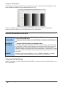
USING THE FLAT FIELD CORRECTION TOOL ...........................................................30
X64 Xcelera-CL PX4 Flat Field Support....................................................30
Set up Dark and Bright Acquisitions with the Histogram Tool .....................30
Verify a Dark Acquisition .................................................................30
Verify a Bright Acquisition ...............................................................31
Flat Field Correction Calibration Procedure ..............................................32
Using Flat Field Correction ....................................................................33
USING THE BAYER FILTER TOOL ........................................................................33
Bayer Filter White Balance Calibration Procedure .....................................34
Using the Bayer Filter ..........................................................................34
SAPERA DEMO APPLICATIONS __________________________________35
GRAB DEMO OVERVIEW .................................................................................35
Using the Grab Demo...........................................................................35
FLAT-FIELD DEMO OVERVIEW ..........................................................................36
Using the Flat Field Demo.....................................................................36
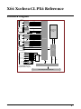
X64 XCELERA-CL PX4 REFERENCE________________________________37
FULL BLOCK DIAGRAM ...................................................................................37
ACQUISITION TIMING ....................................................................................38
LINE TRIGGER SOURCE SELECTION FOR LINESCAN APPLICATIONS .................................39
CORACQ_PRM_EXT_LINE_TRIGGER_SOURCE..........................................39
SHAFT ENCODER INTERFACE TIMING...................................................................40
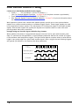
VIRTUAL FRAME TRIGGER FOR LINES SCAN CAMERAS ...............................................42
Synchronization Signals for a Virtual Frame of 10 Lines. ......................42
ACQUISITION METHODS .................................................................................43
TRIGGER TO IMAGE RELIABILITY .......................................................................43
Supported Events and Transfer Methods .................................................44
Trigger Signal Validity .....................................................................45
Supported Transfer Cycling Methods .................................................45
OUTPUT LUT AVAILABILITY .............................................................................46
ii Contents
X64 Xcelera-CL PX4 User's Manual
SUPPORTING NON-STANDARD CAMERA LINK CAMERAS .............................................47
Firmware: Full with Bayer Decoder Method 6...........................................47
X64 XCELERA-CL PX4 SUPPORTED PARAMETERS ...................................................47
Camera Related Capabilities .................................................................47
Camera Related Parameters..................................................................48
VIC Related Parameters .......................................................................51
ACQ Related Parameters ......................................................................55
WINDOWS EMBEDDED 7 INSTALLATION ...............................................................56
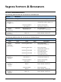
SAPERA SERVERS & RESOURCES ________________________________57
SERVERS AND RESOURCES ..............................................................................57
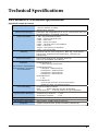
TECHNICAL SPECIFICATIONS ___________________________________58
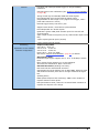
X64 XCELERA-CL PX4 BOARD SPECIFICATIONS .....................................................58
HOST SYSTEM REQUIREMENTS .........................................................................60
EMI CERTIFICATIONS ....................................................................................61
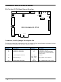
CONNECTOR AND SWITCH LOCATIONS .................................................................62
X64 Xcelera-CL PX4 Board Layout Drawing .............................................62
Connector, Switch, Jumper Description List .............................................62
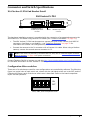
CONNECTOR AND SWITCH SPECIFICATIONS ...........................................................63
X64 Xcelera-CL PX4 End Bracket Detail ..................................................63
Configuration Micro-switches ................................................................63
SW1: General Inputs Signal Switch Point ...........................................64
SW2: Trigger Inputs Signal Switch Point ............................................64
SW3: Normal/Safe Boot Mode & GEN2 Slot Workaround ......................64
SW3-1 Boot Mode Details ................................................................64
SW3-2 GEN2 Slot Workaround Details ...............................................64
Status LEDs Functional Description ........................................................65
J2: Camera Link Connector 1 ................................................................66
J3: Camera Link Connector 2 ................................................................67
Camera Link Camera Control Signal Overview .........................................68
J4: External Signals Connector ..............................................................69
Note 1: General Inputs Specifications................................................69
Note 2: General Outputs Specifications..............................................70
Note 3: External Trigger Input Specifications......................................71
Note 4: Shaft Encoder Input Specifications ........................................72
Note 5: Strobe Output Specifications.................................................73
Note 6: DC Power Details & J7 .........................................................74
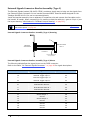
External Signals Connector Bracket Assembly (Type 1) .............................74
External Signals Connector Bracket Assembly (Type 1) Drawing............74
External Signals Connector Bracket Assembly (Type 1) Pinout ..............75
External Signals Connector Bracket Assembly (Type 2) .............................76
External Signals Connector Bracket Assembly (Type 2) Drawing............76
External Signals Connector Bracket Assembly (Type 2) Pinout ..............76
J9: Board Sync ...................................................................................77
CAMERA LINK INTERFACE______________________________________78
CAMERA LINK OVERVIEW ................................................................................78
Rights and Trademarks ........................................................................78
DATA PORT SUMMARY ...................................................................................78
CAMERA SIGNAL SUMMARY .............................................................................79
Video Data ....................................................................................79
Camera Controls ............................................................................79
Communication ..............................................................................79
CAMERA LINK CABLES ...................................................................................79
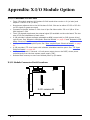
APPENDIX: X-I/O MODULE OPTION ______________________________80
X-I/O MODULE OVERVIEW .............................................................................80
X-I/O Module Connector List & Locations ................................................80
X64 Xcelera-CL PX4 User's Manual
Contents iii
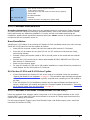
X-I/O MODULE INSTALLATION .........................................................................81
Board Installation................................................................................81
X64 Xcelera-CL PX4 and X-I/O Driver Update ..........................................81
X-I/O MODULE EXTERNAL CONNECTIONS TO THE DB37 ...........................................81
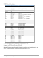
DB37 Pinout Description.......................................................................82
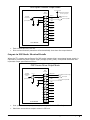
Outputs in NPN Mode: Electrical Details ..................................................82
Outputs in PNP Mode: Electrical Details ..................................................83
Opto-coupled Input: Electrical Details ....................................................84
TTL Input Electrical Details ...................................................................84
X-I/O MODULE SAPERA INTERFACE ...................................................................85
Configuring User Defined Power-up I/O States.........................................85
Using Sapera LT General I/O Demo........................................................86
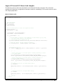
Sapera LT General I/O Demo Code Samples............................................87
Main I/O Demo code .......................................................................87
Function CreateObjects().................................................................88
Output Dialog: CGioOutputDlg class (see Sapera Gui class) ..................88
Input Dialog: CGioInputDlg class. (see Sapera Gui class) .....................89
I/O Event Handling .........................................................................89
CONTACT INFORMATION ______________________________________90
SALES INFORMATION.....................................................................................90
TECHNICAL SUPPORT.....................................................................................91
GLOSSARY OF TERMS _________________________________________92
INDEX _____________________________________________________94
iv Contents
X64 Xcelera-CL PX4 User's Manual
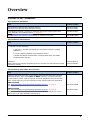
Overview
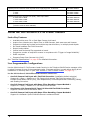
Product Part Numbers
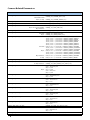
X64 Xcelera-CL PX4 Board
Item
Product Number
X64 Xcelera-CL PX4 Full with 128 MB of memory
X64 Xcelera-CL PX4 Dual with 128 MB of memory
OR-X4C0-XPF00
OR-X4C0-XPD00
X-I/O Module (optional): provides an additional 8 input & 8 output general I/Os
(see "Appendix: X-I/O Module Option" on page 80)
OC-IO01-STD00
For OEM clients, this manual in printed form, is available on request
OC-X4CM-USER0
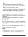
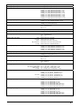
X64 Xcelera-CL PX4 Software
Item
Product Number
Sapera LT version 6.00 or later (7.40 for Windows Vista, Windows 7, or Windows 8)
— required but sold separately
OC-SL00-0000000
1. Sapera LT: Provides everything you will need to build your imaging
application
2. Current Sapera compliant board hardware drivers
3. Board and Sapera documentation (compiled HTML help, and Adobe
Acrobat® (PDF) formats)
(optional)
Sapera Processing Imaging Development Library includes over 600 optimized image
processing routines.
Contact Sales at
Teledyne DALSA
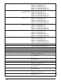
X64 Xcelera-CL PX4 Cables & Accessories
Item
Product Number
(optional) X64 Xcelera-CL PX4 can be shipped with an External Signals Connector
Bracket Assembly, either with a DB37 or DB25 connector (see the two product
numbers below). Either cable, if required, should be specified at the time of order.
Note: clients requiring more I/O connections must add the optional X-I/O Module.
DB37 assembly
see "External Signals Connector Bracket Assembly (Type 1)" on page 74.
This cable assembly connects to J4.
DB25 assembly
see "External Signals Connector Bracket Assembly (Type 2)" on page 76.
Provides direct compatibility with external cables made for products such as the
X64-CL iPro. This cable assembly connects to J4.
X64 Xcelera-CL PX4 User's Manual
OR-X4CC-IOCAB
OR-X4CC-0TIO2
Overview 5
(optional) Power interface cable required when supplying power to cameras
OR-COMC-POW03
(optional) Camera Link Video Input Cable:
1 meter
2 meter
OC-COMC-CLNK0
OC-COMC-CLNK6
(optional) Power Over Camera Link (PoCL) Video Input Cable
2 meter HDR to MDR
1 meter MDR to MDR
2 meter MDR to MDR
OR-COMC-POCLD2
OR-COMC-POCLM1
OR-COMC-POCLM2
(optional) Cable bundle to connect Xcelera-CL PX4 to the X-I/O module
(includes cable OC-IO0C-ANLVDS)
OC-IO0B-ALAM0
About the X64 Xcelera-CL PX4 Frame Grabber
Series Key Features
Available either as a Full or Dual Base Camera Link board
Acquire from Monochrome, Bayer Filter or RGB Cameras, both area scan and linescan
Supports multiple tap formats and multiple tap scan directions, in multiple pixels depths
On board hardware Flat Field Correction
Output lookup tables
Vertical and Horizontal Flip supported on board
Supports a number of acquisition events in compliance with "Trigger to Image Reliability"
RoHS compliant
Supports Power Over Camera Link (PoCL)
See “Technical Specifications” on page 58 for detailed information.
User Programmable Configurations
Use the X64 Xcelera-CL PX4 firmware loader function in the Teledyne DALSA Device manager utility
to select firmware for one of the supported modes. Firmware selection is made either during driver
installation or manually later on (see "X64 Xcelera-CL PX4 Firmware Loader" on page 10).
For the X64 Xcelera-CL PX4 Full board the firmware choices are:
One Full Camera Link Input with Flat Field Correction (installation default selection)
Support for 1 Base, 1 Medium or 1 Full Camera Link camera. Flat Field Correction (FFC)
includes Fixed Pattern Noise (FPN), Pixel Replacement, Photo Response Non Uniformity (PRNU),
and Shading Correction.
One Full Camera Link Input with Bayer Filter Decoding, Sapera Method 1:
Support for 1 Base, 1 Medium or 1 Full Camera Link camera.
One Camera Link Input with 10 Taps @ 8 bits with Flat Field Correction:
Supports camera such as the Basler A504.
One Full Camera Link Input with Bayer Filter Decoding, Sapera Method 6:
Support for the Basler Sprint SPL8192 camera in enhanced mode.
6 Overview
X64 Xcelera-CL PX4 User's Manual
For the X64 Xcelera-CL PX4 Dual board the firmware choices are:
Two independent Base Camera Link Input with Flat Field Correction (installation default
selection)
Support for 1 or 2 Base Camera Link cameras. Flat Field Correction (FFC) includes Fixed Pattern
Noise (FPN), Pixel Replacement, Photo Response Non Uniformity (PRNU), and Shading
Correction.
Two independent Base Camera Link Input with Bayer Filter Decoding, Sapera Method
1:
Support for 1 or 2 Base Camera Link cameras with Hardware Bayer CFA (Color Filter Array)
Decoder. Flat Field Correction is not available in this configuration.
One Medium Camera Link Input with Flat field correction:
Support for 1 Base or 1 Medium Camera Link camera. Flat Field Correction (FFC) includes Fixed
Pattern Noise (FPN), Pixel Replacement, Photo Response Non Uniformity (PRNU), and Shading
Correction.
One Medium Camera Link Input with Bayer Filter Decoding, Sapera Method 1:
Support for 1 Base or 1 Medium Camera Link camera with Hardware Bayer CFA (Color Filter
Array) Decoder. Flat Field Correction is not available in this configuration.
ACUPlus: Acquisition Control Unit
ACUPlus consists of a grab controller, one pixel packer, and one time base generator. ACUPlus
delivers a flexible acquisition front end plus it supports pixel clock rates of up to 85MHz.
ACUPlus acquires variable frame sizes up to 256KB per horizontal line and up to 16 million lines per
frame. ACUPlus can also capture an infinite number of lines from a linescan camera without losing
a single line of data.
ACUPlus supports standard Camera Link multi-tap configurations from 8 to 64-bit/pixels.
Additionally, alternate tap configurations can support up to 8 taps of 8-bits each or optionally 10
tap with alternate firmware.
DTE: Intelligent Data Transfer Engine
The X64 Xcelera-CL PX4 intelligent Data Transfer Engine ensures fast image data transfers
between the board and the host computer with zero CPU usage. The DTE provides a high degree of
data integrity during continuous image acquisition in a non-real time operating system like
Windows. DTE consists of multiple independent DMA units, Tap Descriptor Tables, and Auto-loading
Scatter-Gather tables.
PCI Express x4 Interface
The X64 Xcelera-CL PX4 is a universal PCI Express x4 board, compliant with the PCI Express 1.1
specification. The X64 Xcelera-CL PX4 board achieves transfer rates up to 750 Mbytes/sec. with all
taps used when connected to a corresponding camera or sensor.
The X64 Xcelera-CL PX4 board occupies one PCI Express x4 expansion slot and one chassis
opening (two slots with the optional X-I/O Module Option).
Important:
Older computers may not support the maximum data transfer bandwidth defined for PCI
Express x4.
The X64 Xcelera-CL PX4 board can also be used in an PCI Express x8 slot typically without
issue.
If the computer only has a PCI Express x16 slot, an x4 board must be tested to see if it is
supported. It has been seen that many computer motherboards only support x16 products in
x16 slots (commonly used with graphic video boards).
X64 Xcelera-CL PX4 User's Manual
Overview 7
Advanced Controls Overview
Visual Indicators
X64 Xcelera-CL PX4 features LED indicators to facilitate system installation and setup. These
indicators provide visual feedback on the board status and camera status.
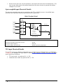
External Event Synchronization
Trigger inputs and strobe signals are provided to precisely synchronize image captures with
external events.
Camera Link Communications ports
One (Full board) or two (Dual board) PC independent communication ports provide Camera Link
camera configurations. These ports do not require addition PC resources like free interrupts or I/O
address space. Accessible via the board device driver, the communication ports present a seamless
interface to Windows-based standard communication applications like HyperTerminal, etc. The
communication ports are accessible directly from the Camera Link connectors.
Quadrature Shaft Encoder
An important feature for web scanning applications, the Quadrature-Shaft-Encoder inputs allow
synchronized line captures from external web encoders.
About the Optional X-I/O Module
The optional X-I/O module adds independent general purpose software controllable I/O signals to
the X64 Xcelera-CL PX4. The X-I/O module provides 2 opto-coupled inputs, 6 logic signal inputs
(5V or 24V), and 8 TTL outputs (NPN or PNP type selectable). The module also makes available 5V
or 12V dc power from the host system.
The X-I/O module can be either purchased with the X64 Xcelera-CL PX4 board or installed into the
computer system at a later time. The module occupies one adjacent PCI slot and connects to the
X64 Xcelera-CL PX4 via a ribbon cable. X-I/O Module external connections are made via the DB37
connector on the module bracket.
X-I/O requires X64 Xcelera-CL PX4 board driver version 1.00 or later and Sapera LT version 6.0 or
later.
See "Appendix: X-I/O Module Option" on page 80 for details and specifications.
Development Software Overview
Sapera++ LT Library
Sapera++ LT is a powerful development library for image acquisition and control. Sapera++ LT
provides a single API across all current and future Teledyne DALSA hardware. Sapera++ LT
delivers a comprehensive feature set including program portability, versatile camera controls,
flexible display functionality and management, plus easy to use application development wizards.
Applications are developed using either C++ or .NET frameworks.
Sapera++ LT comes bundled with CamExpert, an easy to use camera configuration utility to create
new, or modify existing camera configuration files.
Sapera Processing Library
Sapera Processing is a comprehensive set of C++ classes or .NET classes for image processing and
analysis. Sapera Processing offers highly optimized tools for image processing, blob analysis,
search (pattern recognition), OCR and barcode decoding.
8 Overview
X64 Xcelera-CL PX4 User's Manual
Installing X64 Xcelera-CL PX4
Warning! (Grounding Instructions)
Static electricity can damage electronic components. Please discharge any static electrical charge
by touching a grounded surface, such as the metal computer chassis, before performing any
hardware installation.
If you do not feel comfortable performing the installation, please consult a qualified computer
technician.
Important: Never remove or install any hardware component with the computer power on.
Disconnect the power cord from the computer to disable the power standby mode. This prevents
the case where some computers unexpectedly power up when a board is installed.
Installation
Note: To install Sapera LT and the X64 Xcelera-CL PX4 device driver, logon to the workstation as
administrator or with an account that has administrator privileges.
The Sapera LT Development Library (or ‘runtime library’ if application execution without
development is preferred) must be installed before the Xcelera-CL PX4 device driver.
Turn the computer off, disconnect the power cord (disables power standby mode), and open the
computer chassis to allow access to the expansion slot area.
Install the X64 Xcelera-CL PX4 into a free PCI Express x4 expansion slot. Note that some
computer's x16 slot may support x4 board products.
Connect a PC Floppy drive power connector to J7 for PoCL cameras or when DC power is
required on the external signals connector J4.
Close the computer chassis and turn the computer on.
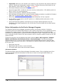
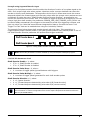
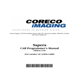
Windows will find the X64 Xcelera-CL PX4 and start its Found New Hardware Wizard. Click
on the Cancel button to close the Wizard.
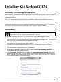
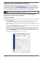
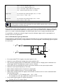
If using Windows Vista, Windows will display its Found New Hardware dialog. Click on the
default "Ask me again later" and continue with the installation. Note that if you select the third
option "Don't show this message again for this device", there will be no prompt if the Teledyne
DALSA board is installed in the same computer.
Figure 1: Found New Hardware
X64 Xcelera-CL PX4 User's Manual
Installing X64 Xcelera-CL PX4 9
Sapera LT Library Installation
Insert the Teledyne DALSA Sapera Essential CD-ROM. If AUTORUN is enabled on your
computer, the installation menu is presented.
If AUTORUN is not enabled, use Windows Explorer and browse to the root directory of the
CD-ROM. Execute launch.exe to start the installation menu and install the required Sapera
components.
Continue with the installation of the board driver as described in the next section.
The installation program will prompt you to reboot the computer.
Refer to Sapera LT User’s Manual for additional details about Sapera LT.
X64 Xcelera-CL PX4 Driver Installation
The X64 Xcelera-CL PX4 board driver supports installation in a Windows XP, Windows Vista,
Windows 7, or Windows 8 system.
After installing Sapera, continue by selecting the X64 Xcelera-CL PX4 driver installation.
Insert the Teledyne DALSA Sapera CD-ROM. If AUTORUN is enabled on your computer, the
installation menu is presented. Install the X64 Xcelera-CL PX4 driver.
If AUTORUN is not enabled, use Windows Explorer and browse to the root directory of the
CD-ROM. Execute launch.exe to start the installation menu and install the X64 Xcelera-CL
PX4 driver. During the late stages of the installation, the X64 Xcelera-CL PX4 firmware
loader application starts. This is described in detail in the following section.
If Windows displays any unexpected message concerning the installed board, power off the
system and verify the X64 Xcelera-CL PX4 is installed in the slot properly.
X64 Xcelera-CL PX4 Firmware Loader
The Device Manager-Firmware Loader program automatically executes at the end of the driver
installation and on every subsequent reboot of the computer. It will determine if the X64 XceleraCL PX4 requires a firmware update. If firmware is required, a dialog displays and it also allows the
user to load firmware for alternate operational modes of the X64 Xcelera-CL PX4.
Important: In the vary rare case of firmware loader errors please see "Recovering from a
Firmware Update Error" on page 23.
Firmware Update: Automatic Mode
Click Automatic to update the X64 Xcelera-CL PX4 firmware. The X64 Xcelera-CL PX4 Full
supports 4 firmware configurations with the default being a Full, Medium, or Base camera with Flat
Field correction.
The X64 Xcelera-CL PX4 Dual board supports 4 firmware configurations with the default being
dual Base cameras with Flat Field correction.
See “Series Key Features” on page 6 and “User Programmable Configurations” on page 6 for details
on all supported modes, which can be selected via a manual firmware update.
If there are multiple X64 Xcelera-CL PX4 boards in the system, all will be updated with new
firmware. If any installed X64 Xcelera-CL PX4 board installed in a system already has the correct
firmware version, an update is not required. In the following screen shot, a single X64 Xcelera-CL
PX4 Full board is installed in the system and the default configuration is ready to be programmed.
10 Installing X64 Xcelera-CL PX4
X64 Xcelera-CL PX4 User's Manual
Firmware Update: Manual Mode
Select Manual mode to load firmware other then the default version or when, in the case of
multiple X64 Xcelera-CL PX4 boards in the same system, each requires different firmware.
The figure below shows the Device Manager manual firmware screen. Information on all installed
X64 Xcelera-CL PX4 boards, their serial numbers, and their firmware components are shown.
A manual firmware update is made as follows:
Select the X64 Xcelera-CL PX4 to update via the board selection box (if there are multiple
boards in the system)
From the Configuration field drop menu select the firmware version required
Click on the Start Update button
Observe the firmware update progress in the message output window
Close the Device manager program when the device reset complete message is shown.
Executing the Firmware Loader from the Start Menu
If required, the X64-Xcelera-CL PX4 Firmware Loader program is executed via the Windows Start
Menu shortcut Start • Programs • Teledyne DALSA • X64 Xcelera-CL PX4 Driver •
Firmware Update. A firmware change after installation would be required to select a different
configuration mode. See "User Programmable Configurations" on page 6.
X64 Xcelera-CL PX4 User's Manual
Installing X64 Xcelera-CL PX4 11
Requirements for a Silent Install
Both Sapera LT and the X64 Xcelera-CL PX4 driver installations share the same installer
technology. When the installations of Teledyne DALSA products are embedded within a third party’s
product installation, the mode can either have user interaction or be completely silent. The
following installation mode descriptions apply to both Sapera and the hardware driver.
Note: You must reboot after the installation of Sapera LT. However, to streamline the installation
process, Sapera LT can be installed without rebooting before installing the board hardware device
drivers. The installations then complete with a single final system reboot.
Perform Teledyne DALSA embedded installations in either of these two ways:
Normal Mode
The default mode is interactive. This is identical to running the setup.exe program manually
from Windows (either run from Windows Explorer or the Windows command line).
Silent Mode
This mode requires no user interaction. A preconfigured “response” file provides the user input.
The installer displays nothing.
Silent Mode Installation
A Silent Mode installation is recommended when integrating Teledyne DALSA products into your
software installation. The silent installation mode allows the device driver installation to proceed
without the need for mouse clicks or other input from a user.
Preparing a Silent Mode Installation requires two steps:
Prepare the response file, which emulates a user.
Invoke the device driver installer with command options to use the prepared response file.
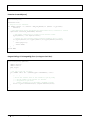
Creating a Response File
Create the installer response file by performing a device driver installation with a command line
switch "-r". The response file is automatically named setup.iss and is saved in the \windows
folder. If a specific directory is desired, the switch –f1 is used.
As an example, to save a response file in the same directory as the installation executable of the
X64 Xcelera-CL PX4, the command line would be:
X64_Xcelera-CL_PX4_1.40.exe –r –f1”.\setup.iss”
Running a Silent Mode Installation
A device driver silent installation, whether done alone or within a larger software installation
requires the device driver executable and the generated response file setup.iss.
Execute the device driver installer with the following command line:
X64_Xcelera-CL_PX4_1.40.exe -s -f1".\setup.iss"
Where the –s switch specifies the silent mode and the –f1 switch specifies the location of the
response file. In this example, the switch –f1".\setup.iss" specifies that the setup.iss file be in the
same folder as the device driver installer.
Note: On Windows Vista, Windows 7 or Windows 8, the Windows Security dialog box will appear
unless one has already notified Windows to ‘Always trust software from “Teledyne DALSA Inc.”
during a previous installation of a driver.
12 Installing X64 Xcelera-CL PX4
X64 Xcelera-CL PX4 User's Manual
Silent Mode Uninstall
Similar to a silent installation, a response file must be prepared first as follows.
Creating a Response File
The installer response file is created by performing a device driver un-installation with a command
line switch "-r". The response file is automatically named setup_uninstall.iss which is saved in
the \windows folder. If a specific directory is desired, the switch “–f1” is used.
As an example, to save a response file in the same directory as the installation executable of the
X64 Xcelera-CL PX4, the command line would be:
X64_Xcelera-CL_PX4_1.40.exe –r –f1”.\setup_uninstall.iss”
Running a Silent Mode Uninstall
Similar to the device driver silent mode installation, the un-installation requires the device driver
executable and the generated response file setup.iss.
Execute the device driver installer with the following command line:
X64_Xcelera-CL_PX4_1.40.exe -s -f1".\setup_uninstall.iss"
Where the –s switch specifies the silent mode and the –f1 switch specifies the location of the
response file. In this example, the switch –f1".\setup_uninstall.iss" specifies that the
setup_uninstall.iss file be in the same folder as the device driver installer.
Silent Mode Installation Return Code
A silent mode installation creates a file “corinstall.ini” in the Windows directory. A section called
[SetupResult] contains the ‘status’ of the installation. A value of 1 indicates that the installation has
started and a value of 2 indicates that the installation has terminated.
A silent mode installation also creates a log file “setup.log” which by default is created in the same
directory and with the same name (except for the extension) as the response file. The /f2 option
enables you to specify an alternative log file location and file name, as in Setup.exe /s
/f2"C:\Setup.log".
The “setup.log” file contains three sections. The first section, [InstallShield Silent], identifies the
version of InstallShield used in the silent installation. It also identifies the file as a log file. The
second section, [Application], identifies the installed application name, version, and the company
name. The third section, [ResponseResult], contains the ‘ResultCode’ indicating whether the silent
installation succeeded. A value of 0 means the installation was successful.
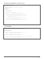
Installation Setup with CorAppLauncher.exe
The installation setup can be run with the CorAppLauncher.exe tool provided with the driver.
Install the board driver and get CorAppLauncher.exe from the \bin directory of the installation.
When running the installation, CorAppLauncher.exe will return only when the installation is
finished.
When run from within a batch file, obtain the installation exit code from the ERRORLEVEL value.
The arguments to CorAppLauncher.exe are
-l: Launch application
-f: Application to launch. Specify a fully qualified path.
As an example:
CorAppLauncher –l –f”c:\driver_install\x64_xcelera-cl_PX4_1.40.exe”
IF %ERRORLEVEL% NEQ 0 goto launch error
X64 Xcelera-CL PX4 User's Manual
Installing X64 Xcelera-CL PX4 13
Note: There is a 32-bit and 64-bit version of CorAppLauncher.exe. When installing the driver,
only the version related to the OS is installed. However, the 32-bit version is usable on either 32bit or 64-bit Windows.
Custom Driver Installation using install.ini
Customize the driver installation by parameters defined in the file “install.ini”. By using this file, the
user can:
Select the user default configuration.
Select different configurations for systems with multiple boards.
Assign a standard Serial COM port to board.
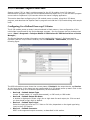
Creating the install.ini File
Install the driver in the target computer. All X64 Xcelera-CL PX4 boards required in the system
must be installed.
Configure each board’s acquisition firmware using the Teledyne DALSA Device Manager tool
(see "Device Manager – Board Viewer" on page 17).
If a standard Serial COM port is required for any board, use the Sapera Configuration tool (see
"COM Port Assignment" on page 16).
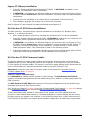
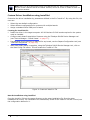
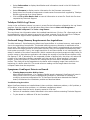
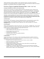
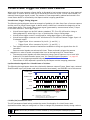
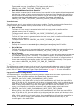
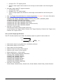
When each board setup is complete, using the Teledyne DALSA Device Manager tool, click on
the Save Config File button. This will create the “install.ini” file.
Figure 2: Create an install.ini File
Run the Installation using install.ini
Copy the install.ini file into the same directory as the setup installation file. Run the setup
installation as normal. The installation will automatically check for an install.ini file and if found, use
the configuration defined in it.
14 Installing X64 Xcelera-CL PX4
X64 Xcelera-CL PX4 User's Manual
Upgrading Sapera or any Board Driver
When installing a new version of Sapera or a Teledyne DALSA acquisition board driver in a
computer with a previous installation, the current version must be un-installed first. Described
below are two upgrade situations. Note that if the board is installed in a different slot, the new
hardware wizard opens. Answer as instructed in section “Installation” on page 9.
Board Driver Upgrade Only
Minor upgrades to acquisition board drivers are typically distributed as ZIP files available in the
Teledyne DALSA web site http://www.teledynedalsa.com/imaging/support/. Board driver revisions
are also available on the next release of the Sapera CD-ROM.
Often minor board driver upgrades do not require a new revision of Sapera. To confirm that the
current Sapera version will work with the new board driver:
Check the new board driver ReadMe file before installing, for information on the minimum
Sapera version required.
If the ReadMe file does not specify the Sapera version, contact Teledyne DALSA Technical
Support (see "Technical Support" on page 91 ).
To upgrade the board driver only:
Logon the computer as an administrator or with an account that has administrator
privileges.
In Windows XP, from the start menu select Start • Settings • Control Panel • Add or
Remove Programs. Select the Teledyne DALSA Xcelera board driver and click Remove.
Windows XP only:
When the driver un-install is complete, reboot the computer.
Logon the computer as an administrator again.
In Windows Vista, Windows 7, from the start menu select Start • Settings • Control
Panel • Programs and Features. Double-click the Teledyne DALSA Xcelera board driver
and click Remove.
Install the new board driver. Run Setup.exe if installing manually from a downloaded driver
file.
If the new driver is on a Sapera CD-ROM follow the installation procedure described in "X64
Xcelera-CL PX4 Driver" on page 10.
Note that you can not install a Teledyne DALSA board driver without Sapera LT installed on
the computer.
Sapera and Board Driver Upgrades
When upgrading both Sapera and the acquisition board driver, follow the procedure described
below.
Logon the computer as an administrator or with an account that has administrator
privileges.
In Windows XP, from the start menu select Start • Settings • Control Panel • Add or
Remove Programs. Select the Teledyne DALSA Xcelera board driver and click Remove.
Follow by also removing the older version of Sapera LT.
In Windows Vista/7, from the start menu select Start • Settings • Control Panel •
Programs and Features. Double-click the Teledyne DALSA Xcelera board driver and click
Remove. Follow by also removing the older version of Sapera LT.
Reboot the computer and logon the computer as an administrator again.
Install the new versions of Sapera and the board driver as if this was a first time
installation. See "Sapera LT Library Installation" on page 10 and "X64 Xcelera-CL PX4
Driver" on page 10 for installation procedures.
X64 Xcelera-CL PX4 User's Manual
Installing X64 Xcelera-CL PX4 15
Using the Camera Link Serial Control Port
The Camera Link cabling specification includes a serial communication port for direct camera
control by the frame grabber (see "J2: Camera Link Connector 1 " on page 66). The X64 XceleraCL PX4 driver supports this serial communication port either directly or by mapping it to a host
computer COM port. Any serial port communication program, such as Windows HyperTerminal, can
connect to the camera in use and modify its function modes via its serial port controls. The X64
Xcelera-CL PX4 serial port supports communication speeds from 9600 to 921600 bps.
Note: If your serial communication program can directly select the X64 Xcelera-CL PX4 serial
port then mapping to a system COM port is not necessary.
The X64 Xcelera-CL PX4 serial port is mapped to an available COM port by using the Sapera
Configuration tool. Run the program from the Windows start menu: Start • Programs •
Teledyne DALSA • Sapera LT • Sapera Configuration.
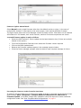
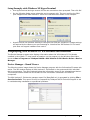
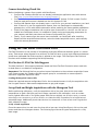
COM Port Assignment
The lower section of the Sapera Configuration program screen contains the serial port configuration
menu. Configure as follows:
Use the Physical Port drop menu to select the Sapera board device from all available
Sapera boards with serial ports (when more then one board is in the system).
Use the Maps to drop menu to assign an available COM number to that Sapera board serial
port.
Click on the Save Settings Now button then the Close button. You are prompted to reboot
your computer to enable the serial port mapping.
The X64 Xcelera-CL PX4 serial port, now mapped to COM3 in this example, is available as a
serial port to any serial port application for camera control. Note that this serial port is not
listed in the Windows Control Panel•System Properties•Device Manager because it is
a logical serial port mapping.
An example setup using Windows HyperTerminal follows.
16 Installing X64 Xcelera-CL PX4
X64 Xcelera-CL PX4 User's Manual
Setup Example with Windows XP HyperTerminal
Run HyperTerminal and type a name for the new connection when prompted. Then click OK.
On the following dialog screen select the port to connect with. The port could be the COM
port mapped to the X64 Xcelera-CL PX4 or the COM device as shown in this example.
HyperTerminal now presents a dialog to configure the COM port properties. Change settings
as required by the camera you are connecting to. Note that the X64 Xcelera-CL PX4 serial
port does not support hardware flow control.
Displaying X64 Xcelera-CL PX4 Board Information
The Device Manager program also displays information about the X64 Xcelera-CL PX4 boards
installed in the system. To view board information run the program via the Windows Start Menu
shortcut Start • Programs • Teledyne DALSA • X64 Xcelera-CL PX4 Device Driver • Device
Manager.
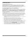
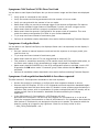
Device Manager – Board Viewer
The following screen image shows the Device Manager program with the Information/Firmware tab
active. The left window displays all X64 Xcelera-CL PX4 boards in the system and their individual
device components. The right window displays the information stored in the selected board device.
This example screen shows the X64 Xcelera-CL PX4 information contained in the EEProm
component.
The X64 Xcelera-CL PX4 device manager report file (BoardInfo.txt) is generated by clicking File •
Save Device Info. This report file may be requested by Teledyne DALSA Technical Support to aid
in troubleshooting installation or operational problems.
X64 Xcelera-CL PX4 User's Manual
Installing X64 Xcelera-CL PX4 17
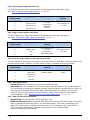
Configuring Sapera
Viewing Installed Sapera Servers
The Sapera configuration program (Start • All Programs • Teledyne DALSA • Sapera LT •
Sapera Configuration) allows the user to see all available Sapera servers for the installed
Sapera-compatible boards. The System entry represents the system server. It corresponds to the
host machine (your computer) and is the only server that should always be present.
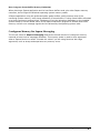
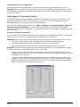
Increasing Contiguous Memory for Sapera Resources
The Contiguous Memory section lets the user specify the total amount of contiguous memory (a
block of physical memory, occupying consecutive addresses) reserved for the resources needed for
Sapera buffers allocation and Sapera messaging. For both items, the Requested value dialog
box shows the driver default memory setting while the Allocated value displays the amount of
contiguous memory that has been allocated successfully. The default values will generally satisfy
the needs of most applications.
The Sapera buffers value determines the total amount of contiguous memory reserved at boot
time for the allocation of dynamic resources used for host frame buffer management such as DMA
descriptor tables plus other kernel needs. Adjust this value higher if your application generates any
out-of-memory error while allocating host frame buffers or when connecting the buffers via a
transfer object. You can approximate the amount of contiguous memory required as follows:
Calculate the total amount of host memory used for frame buffers
[ number of frame buffers • number of pixels per line • number of lines • (2 - if buffer is 10
or 12 bits) ].
Provide 1MB for every 256 MB of host frame buffer memory required.
Add an additional 1 MB if the frame buffers have a short line length, say 1k or less
( the increased number of individual frame buffers requires more resources ).
Add an additional 2 MB for various static and dynamic Sapera resources.
Add the amount of memory needed for DMA tables using the formula (Sapera 7.10 and up):
[number of frame buffers • number of lines • 16 • (line length in bytes / 4kB)].
Test for any memory error when allocating host buffers. Simply use the Buffer menu of the
Sapera Grab demo program (see "Grab Demo Overview" on page 35) to allocate the
number of host buffers required for your acquisition source. Feel free to test the maximum
limit of host buffers possible on your host system – the Sapera Grab demo will not crash
when the requested number of host frame buffers cannot be allocated.
18 Installing X64 Xcelera-CL PX4
X64 Xcelera-CL PX4 User's Manual
Host Computer Frame Buffer Memory Limitations
When planning a Sapera application and its host frame buffers used, plus other Sapera memory
resources, do not forget the Windows operating system memory needs.
A Sapera application using the preferred scatter gather buffers could consume most of the
remaining system memory, with a large allocation of frame buffers. If using frame buffers allocated
as a single contiguous memory block, Windows will limit the allocation dependent on the installed
system memory. Use the Buffer menu of the Sapera Grab demo program to allocate host buffer
memory until an error message signals the limit allowed by the operating system used.
Contiguous Memory for Sapera Messaging
The current value for Sapera messaging determines the total amount of contiguous memory
reserved at boot time for messages allocation. This memory space is used to store arguments
when a Sapera function is called. Increase this value if you are using functions with large
arguments, such as arrays and experience any memory errors.
X64 Xcelera-CL PX4 User's Manual
Installing X64 Xcelera-CL PX4 19
Troubleshooting Problems
Overview
The X64 Xcelera-CL PX4 (and the X64 family of products) is tested by Teledyne DALSA in a variety
of computers. Although unlikely, installation problems may occur due to the constant changing
nature of computer equipment and operating systems. This section describes what the user can
verify to determine the problem or the checks to make before contacting Technical Support.
If you require help and need to contact Technical Support, make detailed notes on your installation
and/or test results for our technical support to review. See "Technical Support" on page 91 for
contact information.
Problem Type Summary
X64 Xcelera-CL PX4 problems are either installation types where the board hardware is not
recognized on the PCIe bus (i.e. trained) or function errors due to camera connections or
bandwidth issues. The following links jump to various topics in this troubleshooting section.
First Step: Check the Status LED
A RED Status LED 1 indicates a camera problem, while various Green states indicate the acquisition
mode.
Status LED 2, if flashing RED, indicates a PCIe bus problem. If you run the PCI Diagnostics tool, the
LX1 is not in the PCI device list. If the board is installed in a computer which supports PCIe GEN2
expansion slots, see section "SW3-2 GEN2 Slot Workaround Details" on page 64.
The complete status LED description is available in the technical reference section (see "Status
LEDs Functional Description" on page 65).
Possible Installation Problems
Hardware PCI bus conflict: When a new installation produces PCI bus error messages or the
board driver doesn't install, it is important to verify that there are no conflicts with other PCI or
system devices already installed. Use the Teledyne DALSA PCI Diagnostic tool as described in
"Checking for PCI Bus Conflicts" on page 21. Also verify the installation via the "Driver
Information via the Device Manager Program" on page 24.
Gen2 slot errors: There is a PCI bus error message from the computer bios. Follow the
instructions "GEN2 PCI Slot Computer Issue" on page 23.
BSOD (blue screen) following a board reset: After programming the board with different
firmware, the computer displays the BSOD when the board is reset (see "BSOD (blue screen)
Following a Board Reset" on page 23).
Verify Sapera and Board drivers: If there are errors when running applications, confirm that
all Sapera and board drivers are running. See "Sapera and Hardware Windows Drivers" on page
23 for details. In addition, Teledyne DALSA technical support will ask for the log file of
messages by board drivers. Follow the instructions describe in "Teledyne DALSA Log Viewer" on
page 25.
Firmware update error: There was an error during the board firmware update procedure.
This usually is easily corrected by the user. Follow the instructions "Recovering from a Firmware
Update Error" on page 23.
Installation went well but the board doesn't work or stopped working. Review theses steps
described in "Symptoms: CamExpert Detects no Boards" on page 25.
X64 Xcelera-CL PX4 User's Manual
Troubleshooting Problems 20
Possible Functional Problems
Driver Information: Use the Teledyne DALSA Device Manager program to view information
about the installed X64 Xcelera-CL PX4 board and driver. See "Driver Information via the
Device Manager Program" on page 24.
On-Board Image Memory Requirements: The X64 Xcelera-CL PX4 on-board memory
provides two frame buffers large enough for most imaging situations. See "On-board Image
Memory Requirements for Acquisitions" on page 25 for details on the on board memory and
possible limitations.
Sometimes the problem symptoms are not the result of an installation issue but due to other
system issues. Review the sections described below for solutions to various X64 Xcelera-CL PX4
functional problems.
"Symptoms: X64 Xcelera-CL PX4 Does Not Grab" on page 26
"Symptoms: Card grabs black" on page 26
"Symptoms: Card acquisition bandwidth is less than expected" on page 26
Troubleshooting Procedures
The following sections provide information and solutions to possible X64 Xcelera-CL PX4 installation
and functional problems. These topics are summarized in the previous section of this manual.
Checking for PCI Bus Conflicts
One of the first items to check when there is a problem with any PCI board is to examine the
system PCI configuration and ensure that there are no conflicts with other PCI or system devices.
The Teledyne DALSA PCI Diagnostic program (cpcidiag.exe) allows examination of the PCI
configuration registers and can save this information to a text file. Run the program via the
Windows Start Menu shortcut Start • All Programs • Teledyne DALSA • Sapera LT • Tools •
PCI Diagnostics.
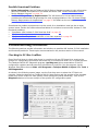
As shown in the following screen image, use the first drop menu to select the PCI device to
examine. Select the device from Teledyne DALSA. Note the bus and slot number of the installed
board (this will be unique for each system unless systems are setup identically). Click on the
Diagnostic button to view an analysis of the system PCI configuration space.
X64 Xcelera-CL PX4 User's Manual
Troubleshooting Problems 21
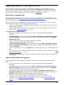
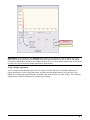
Clicking on the Diagnostic button opens a new window with the diagnostic report. From the PCI
Bus Number drop menu select the bus number that the X64 Xcelera-CL PX4 is installed in—in this
example the slot is bus 2.
The window now shows the I/O and memory ranges used by each device on the selected PCI bus.
The information display box will detail any PCI conflicts. If there is a problem, click on the Save
button. A file named ‘pcidiag.txt’ is created (in the Sapera\bin directory) with a dump of the PCI
configuration registers. Email this file when requested by the Teledyne DALSA Technical Support
group along with a full description of your computer.
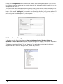
Windows Device Manager
In Windows use the Start Menu shortcut Start • Settings • Control Panel • System •
Hardware • Device Manager. As shown in the following screen images, look for X64 Xcelera-CL
PX4 board under “Imaging Devices”. Double-click and look at the device status. You should see
“This device is working properly.” Go to “Resources” tab and make certain that the device is
mapped and has an interrupt assigned to it, without any conflicts.
22 Troubleshooting Problems
X64 Xcelera-CL PX4 User's Manual
GEN2 PCI Slot Computer Issue
At boot time, the PX4 status LED 2 keeps on flashing red. If you run the PCI Diagnostics tool, the
PX4 is not in the PCI device list. If the board is installed in a computer which supports PCIe GEN2
expansion slots, see section "SW3-2 GEN2 Slot Workaround Details" on page 64.
BSOD (blue screen) Following a Board Reset
Teledyne DALSA engineering has identified cases where a PC will falsely report a hardware
malfunction when the X64 Xcelera-CL PX4 board is reset. The symptoms will be a Windows blue
screen or PC that freezes following a board reset. The solution to this problem is to install the
driver using the switch “/cr”, indicating to the driver that a reset of the board must not be allowed
and that a reboot of the computer is needed instead.
Example: X64_Xcelera-CL_PX4_1.00.00.0000.exe /cr
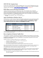
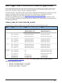
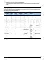
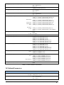
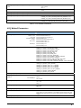
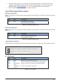
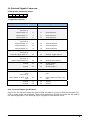
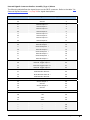
Sapera and Hardware Windows Drivers
The next step is to make certain the appropriate Teledyne DALSA drivers have started successfully
during the boot sequence. Example, click on the Start • Programs • Accessories • System
Tools • System Information • Software Environment. Click on System Drivers. Make
certain the following drivers have started for the X64 Xcelera-CL PX4.
Device
Description
Type
Started
CorX64Expre4x
X64 Xcelera-CL PX4 messaging
Kernel Driver
Yes
CorLog
Sapera Log viewer
Kernel Driver
Yes
CorMem
Sapera Memory manager
Kernel Driver
Yes
CorPci
Sapera PCI configuration
Kernel Driver
Yes
CorSerial
Sapera Serial Port manager
Kernel Driver
Yes
Teledyne DALSA Technical Support may request that you check the status of these drivers as part
of the troubleshooting process.
Recovering from a Firmware Update Error
This procedure is required if any failure occurred while updating the X64 Xcelera-CL PX4 firmware
on installation or during a manual firmware upgrade. On the rare occasion the board has corrupted
firmware, any Sapera application such as CamExpert or the grab demo program will not find an
installed board to control.
Possible reasons for firmware loading errors or corruption are:
Computer system mains power failure or deep brown-out.
PCI bus or checksum errors.
PCI bus timeout conditions due to other devices.
User forcing a partial firmware upload using an invalid firmware source file.
When the X64 Xcelera-CL PX4 firmware is corrupted, executing a manual firmware upload will not
work because the firmware loader can not communicate with the board. In an extreme case,
corrupted firmware may even prevent Windows from booting.
Solution: The user manually forces the board to initialize from write protected firmware designed
only to allow driver firmware uploads. When the firmware upload is complete, the board is then
rebooted to initialize in its normal operational mode.
Note that this procedure may require removing the X64 Xcelera-CL PX4 board several times
from the computer.
X64 Xcelera-CL PX4 User's Manual
Troubleshooting Problems 23
Important: Referring to the board's user manual (in the connectors and jumpers reference
section), identify the configuration switch location. The Boot Recovery Mode switch for the
X64 Xcelera-CL PX4 is SW3-1 (see "SW3: " on page 64).
Shut down Windows and power OFF the computer.
Move the switch SW3-1 to ON, for the boot recovery mode position. (The default position is
SW3-1 to OFF for normal operation).
Power on the computer. Windows will boot normally.
When Windows has started, do a manual firmware update procedure to update the firmware
again (see "Firmware Update: Manual Mode" on page 11).
When the update is complete, shut down Windows and power off the computer.
Set the SW3-1 switch back to the OFF position (i.e. default position) and power on the
computer once again.
Verify that the frame grabber is functioning by running a Sapera application such as
CamExpert. The Sapera application will now be able to communicate with the X64 XceleraCL PX4 board.
Driver Information via the Device Manager Program
The Teledyne DALSA Device Manager program provides a convenient method of collecting
information about the installed X64 Xcelera-CL PX4. System information such as operating system,
computer CPU, system memory, PCI configuration space, plus X64 Xcelera-CL PX4 firmware
information can be displayed or written to a text file (default file name – BoardInfo.txt). Note that
this is a second function mode of the same program used to manually upload firmware to the X64
Xcelera-CL PX4.
Execute the program via the Windows Start Menu shortcut Start • All Programs • Teledyne
DALSA • X64 Xcelera-CL PX4 Device Driver • Device Manager. If the Device Manager
program does not run, it will exit with a message that the board was not found. Since the X64
Xcelera-CL PX4 board must have been in the system to install the board driver, possible reasons
for an error are:
Board was removed
Board driver did not start or was terminated
PCI conflict after some other device was installed
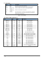
Information Window
The following figure shows the Device Manager information screen. Click to highlight one of the
board components and the information for that item is shown on the right hand window, as
described below.
24 Troubleshooting Problems
X64 Xcelera-CL PX4 User's Manual
Select Information to display identification and information stored in the X64 Xcelera-CL
PX4 firmware.
Select Firmware to display version information for the firmware components.
Select one of the firmware components to load custom firmware when supplied by Teledyne
DALSA engineering for a future feature.
Click on File • Save Device Info to save all information to a text file. Email this file when
requested by Technical Support.
Teledyne DALSA Log Viewer
A step in the verification process is to save in a text file the information collected by the Log Viewer
program. Run the program via the Windows Start Menu shortcut Start • All Programs •
Teledyne DALSA • Sapera LT • Tools • Log Viewer.
The Log Viewer lists information about the installed board drivers. Click on File • Save and you will
be prompted for a text file name to save the Log Viewer contents. Email this text file to Teledyne
DALSA Technical Support when requested or as part of your initial contact email.
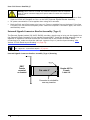
On-board Image Memory Requirements for Acquisitions
The X64 Xcelera-CL PX4 allocates by default two frame buffers in on-board memory, each equal in
size to the acquisition frame buffer. This double buffering memory allocation is automatic at the
driver level. Two buffers will ensure that the acquired video frame is complete and not corrupted in
cases where the image transfer to host system memory may be interrupted and delayed by other
host system processes. That is, the image acquisition to one frame buffer is not interrupted by any
delays in transfer of the other frame buffer (which contains the previously acquired video frame) to
system memory. Note that an application can change the number of on-board frame buffers using
the Sapera LT API. If allocation for the requested number of buffers fails, the driver will reduce the
number of on-board frame buffers requested until they can all fit. When reaching 2 on-board
buffers, if they still cannot fit, the driver will reduce the size such that it allocates two partial
buffers. This mode will write image data to the buffer while wrapping image lines around to the
beginning of a buffer when full. This mode relies on reading out the image data to the host
computer faster than the acquisition.
Symptoms: CamExpert Detects no Boards
If using Sapera version 6.00 or later:
When starting CamExpert, if no Teledyne DALSA board is detected, CamExpert will start in
offline mode. There is no error message and CamExpert is functional for creating or
modifying a camera configuration file. If CamExpert should have detected the installed
board, troubleshoot the installation problem as described below.
Troubleshooting Procedure
When CamExpert detects no installed board, there could be a hardware problem, a PnP problem, a
PCI problem, a kernel driver problem, or a software installation problem.
Make certain that the card is properly seated in PCIe slot.
Perform all installation checks described in this section before contacting Technical Support.
Try the board in a different PCIe slot if available.
X64 Xcelera-CL PX4 User's Manual
Troubleshooting Problems 25
Symptoms: X64 Xcelera-CL PX4 Does Not Grab
You are able to start Sapera CamExpert but you do not see an image and the frame rate displayed
is 0.
Verify power is connected to the camera.
Verify the camera and timing parameters with the camera in free run mode.
Verify you can grab with the camera in free run mode.
Make certain that you provide an external trigger if the camera configuration file requires
one. Use the software trigger feature of CamExpert if you do not have a trigger source.
Make certain that the camera is properly connected to the cable.
Make certain that the camera is configured for the proper mode of operation. This must
match the camera configuration file. Refer to your camera datasheet.
Try to snap one frame instead of continuous grab.
Perform all installation checks described in this section before contacting Technical Support.
Symptoms: Card grabs black
You are able to use Sapera CamExpert, the displayed frame rate is as expected, but the display is
always black.
Set your camera to manual exposure mode and set the exposure to a longer period, plus
open the lens iris.
Try to snap one frame instead of continuous grab.
Make certain that the input LUT is not programmed to output all ‘0’s.
This problem is sometimes caused by a PCIe transfer issue. No PCIe transfer takes place, so
the frame rate is above 0 but nevertheless no image is displayed in CamExpert.
Make certain that BUS MASTER bit in the PCIe configuration space is activated. Look in PCI
Diagnostics for BM button under “Command” group. Make certain that the BM button is
activated.
Perform all installation checks described in this section before contacting Technical Support.
Symptoms: Card acquisition bandwidth is less than expected
The X64 Xcelera-CL PX4 acquisition bandwidth is less than expected.
Review the system for problems or conflicts with other expansion boards or drivers.
Remove other PCI Express, PCI-32 or PCI-64 boards and check acquisition bandwidth again.
engineering has seen this case where other PCI boards in some systems cause limitations in
transfers. Each system, with its combination of system motherboard and PCI boards, will be
unique and will need to be tested for bandwidth limitations affecting the imaging
application.
Is the X64 Xcelera-CL PX4 installed in a PCI Express x16 slot?
Note that some computer's x16 slot may only support non x16 boards at x1 or not at all.
Check the computer documentation or test an X64 Xcelera-CL PX4 installation. Note that the
X64 Xcelera-CL PX4 board is not designed to function at x1 speeds. The speed at which the
board is running at is logged in the LogViewer. Check for an entry similar to this:
“…X64_FPGA_GetPciSpeed = x8…”
26 Troubleshooting Problems
X64 Xcelera-CL PX4 User's Manual
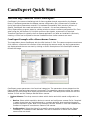
CamExpert Quick Start
Interfacing Cameras with CamExpert
CamExpert is the camera interfacing tool for frame grabber boards supported by the Sapera
library. CamExpert generates the Sapera camera configuration file (yourcamera.ccf) based on
timing and control parameters entered. For backward compatibility with previous versions of
Sapera, CamExpert also reads and writes the *.cca and *.cvi camera parameter files.
Every Sapera demo program starts by a dialog window to select a camera configuration file. Even
when using the X64 Xcelera-CL PX4 with common video signals, a camera file is required.
Therefore CamExpert is typically the first Sapera application run after an installation. Obviously
existing .ccf files can be copied to the new installation when similar cameras are used.
CamExpert Example with a Monochrome Camera
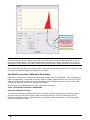
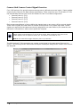
The image below shows CamExpert with the X64 Xcelera-CL PX4. The camera outputs monochrome
8-bit video on a Camera Link interface. After selecting the camera model, the timing parameters
are displayed and the user can test by clicking on Grab. Descriptions of the CamExpert windows
follows the image.
CamExpert groups parameters into functional categories. The parameters shown depend on the
frame grabber used and what camera is connected. The parameter values are either the camera
defaults or the last stored value when the camera was used. The descriptions below are with the
Xcelera-CL PX4 and the Teledyne DALSA Falcon camera.
Device Selector: Two drop menus to select which device and which saved configuration to
use.
Device: Select which acquisition device to control and configure a camera file for. Required
in cases where there are multiple boards in a system and also when one board supports
multiple acquisition types. Note in this example, the X64 Xcelera-CL PX4 was installed with
firmware to support a monochrome Camera Link camera.
Configuration: Select the timing for a specific camera model included with the Sapera
installation or a standard video standard. The User's subsection is where user created
camera files are stored.
X64 Xcelera-CL PX4 User's Manual
CamExpert Quick Start 27
Parameter Groups: Select a function category and change parameter values as required.
Descriptions for the camera parameters change dependent on the camera. The following
information was obtained by using a Teledyne DALSA Falcon camera.
Camera Information: Provides static camera parameters along with a dialog to save a
user setup.
Camera Control: Basic and advanced parameters used to define the timing and pixel type
of the camera. Select the pixel mode, Horizontal active resolution, Vertical Resolution (for
area scan sensors), Pixel Clock frequency, Camera sensor readout type, Binning, etc.
dependent on the camera used. This group is sufficient to configure a free-running camera.
External Trigger: Parameters to configure the external trigger characteristics.
Image Buffer and ROI: Control of the host buffer dimension and format.
Display: An important component of CamExpert is its live acquisition display window which
allows immediate verification of timing or control parameters without the need to run a
separate acquisition program. Grab starts continuous acquisition (button then toggles to
Freeze to stop). Snap is a single frame grab. Trigger is a software trigger to emulate an
external source.
Output Messages and Video Status Bar: Events and errors are logged for review. Camera
connection status is displayed where green indicates signal present.
Camera Link Serial Command: Select this Tab to open a serial command port to the camera.
This allows the user to issue configuration commands if supported by the camera.
For context sensitive help click on the
button then click on a camera configuration parameter.
A short description of the configuration parameter will be shown in a popup. Click on the
button to open the help file for more descriptive information on CamExpert.
CamExpert Demonstration and Test Tools
The CamExpert utility also includes a number of demonstration features which make CamExpert
the primary tool to configure, test and calibrate your camera and imaging setup. Display tools
include, image pixel value readout, image zoom, and line profiler.
Functional tools include hardware Flat Field calibration and operation support (see “Using the Flat
Field Correction Tool” on page 30), plus support for either hardware based or software Bayer filter
camera decoding with auto white balance calibration (see “Using the Bayer Filter Tool” on page
33).
Camera Types & Files Applicable to the X64 Xcelera-CL
PX4
The X64 Xcelera-CL PX4 supports digital area scan or linescan cameras using the Camera Link
interface standard. See "X64 Xcelera-CL PX4 End Bracket Detail" on page 63 for information on
connecting a Camera Link camera.
Contact Teledyne DALSA or browse our web site [http://www.teledynedalsa.com/imaging/support/
] for the latest information and application notes on X64 Xcelera-CL PX4 supported cameras.
Camera Files Distributed with Sapera
The Sapera distribution CDROM includes camera files for a selection of X64 Xcelera-CL PX4
supported cameras. Using the Sapera CamExpert program, you may use the camera files (CCA)
provided to generate a camera configuration file (CCF) that describes the desired camera and
frame grabber configuration..
28 CamExpert Quick Start
X64 Xcelera-CL PX4 User's Manual
Teledyne DALSA continually updates a camera application library composed of application
information and prepared camera files. Camera files are ASCII text and can be read with Windows
Notepad on any computer without having Sapera installed.
Overview of Sapera Acquisition Parameter Files (*.ccf or *.cca/*.cvi)
Concepts and Differences between the Parameter Files
There are two components to the legacy Sapera acquisition parameter file set: CCA files (also
called cam-files) and CVI files (also called VIC files, i.e. video input conditioning). The files store
video-signal parameters (CCA) and video conditioning parameters (CVI), which in turn simplifies
programming the frame-grabber acquisition hardware for the camera in use. Sapera LT 5.0
introduces a new camera configuration file (CCF) that combines the CCA and CVI files into one file.
Typically, a camera application will use a CCF file per camera operating mode (or one CCA file in
conjunction with several CVI files, where each CVI file defines a specific camera operating mode).
An application can also have multiple CCA/CCF files so as to support different image format modes
supported by the camera or sensor (such as image binning or variable ROI).
CCF File Details
Files using the “.CCF” extension, (Camera Configuration files), are essentially the camera (CCA)
and frame grabber (CVI) parameters grouped into one file for easier configuration file
management. This is the default Camera Configuration file used with Sapera LT 5.0 and the
CamExpert utility.
CCA File Details
Teledyne DALSA distributes camera files using the “.CCA” extension, (CAMERA files), which contain
all parameters describing the camera video signal characteristics and operation modes (what the
camera outputs). The Sapera parameter groups within the file are:
Video format and pixel definition.
Video resolution (pixel rate, pixels per line, lines per frame).
Synchronization source and timing.
Channels/Taps configuration.
Supported camera modes and related parameters.
External signal assignment.
CVI File Details
Legacy files using the “.CVI” extension contain all operating parameters related to the frame
grabber board - what the frame grabber can actually do with camera controls or incoming video.
The Sapera parameter groups within the file are:
Activate and set any supported camera control mode or control variable.
Define the integration mode and duration.
Define the strobe output control.
Allocate the frame grabber transfer ROI, the host video buffer size and buffer type
(RGB888, RGB101010, MONO8, MONO16).
Configuration of line/frame trigger parameters such as source (internal via the frame
grabber /external via some outside event), electrical format (TTL, RS-422, OPTO-isolated),
and signal active edge or level characterization.
X64 Xcelera-CL PX4 User's Manual
CamExpert Quick Start 29
Camera Interfacing Check List
Before interfacing a camera from scratch with CamExpert:
Confirm that Teledyne DALSA has not already published an application note with camera
files [http://www.teledynedalsa.com/imaging/support/ ].
Confirm that the correct version or board revision of X64 Xcelera-CL PX4 is used. Confirm
that the required firmware is loaded into the X64 Xcelera-CL PX4 .
Confirm that Sapera does not already have a .cca file for your camera installed on your hard
disk. If there is a .cca file supplied with Sapera, then use CamExpert to automatically
generate the .ccf file with default parameter values matching the frame grabber capabilities.
Check if the Sapera installation has a similar type of camera file. A similar .cca file can be
loaded into CamExpert where it is modified to match timing and operating parameters for
your camera, and lastly save them as Camera Configuration file (.ccf).
Finally, if your camera type has never been interfaced, run CamExpert after installing
Sapera and the acquisition board driver, select the board acquisition server, and manually
enter the camera parameters.
Using the Flat Field Correction Tool
Flat Field Correction is the process of eliminating small gain differences between pixels in a sensor
array. That sensor when exposed to a uniformly lit field will have no gray level differences between
pixels when calibrated flat field correction is applied to the image. The CamExpert Flat Field tool
functions with hardware supporting flat field processing.
X64 Xcelera-CL PX4 Flat Field Support
The X64 Xcelera-CL PX4 supports hardware based real-time Flat Field Correction when used with
its dual Base or one Medium configuration.
Important: Flat field and flat line correction impose limitations to the maximum acquisition frame
rate. Please contact the Teledyne DALSA support group for more details on camera specific
maximum supported acquisition rates.
Loading the Required Camera File
Select the required camera configuration file for the connected camera. Verify the acquisition with
the live grab function. Make camera adjustments to get good images.
Set up Dark and Bright Acquisitions with the Histogram Tool
Before performing calibration, verify the acquisition with a live grab. Also at this time make
preparations to grab a flat light gray level image, required for the calibration, such as a clean
evenly lighted white wall or non-glossy paper with the lens slightly out of focus. Ideally a controlled
diffused light source aimed directly at the lens should be used. Note the lens iris position for a bright but not
saturated image. Additionally check that the lens iris closes well or have a lens cover to grab the
dark calibration image.
Verify a Dark Acquisition
Close the camera lens iris and cover the lens with a lens cap. Using CamExpert, click on the grab
button and then the histogram button. The following figure shows a typical histogram for a very
dark image.
30 CamExpert Quick Start
X64 Xcelera-CL PX4 User's Manual
Indicates one or more
“hot” pixels
Average dark pixel value
Important: In this example, the average pixel value for the frame is close to black. Also note
that most sensors will show a much higher maximum pixel value due to one or more "hot pixels".
The sensor specification accounts for a small number of hot or stuck pixels (pixels that do not react
to light over the full dynamic range specified for that sensor).
Verify a Bright Acquisition
Aim the camera at a diffused light source or evenly lit white wall with no shadows falling on it.
Using CamExpert, click on the grab button and then the histogram button. Use the lens iris to
adjust for a bright gray approximately around a pixel value of 200 (for 8-bit pixels). The following
figure shows a typical histogram for a bright gray image.
X64 Xcelera-CL PX4 User's Manual
CamExpert Quick Start 31
Minimum should not be black
unless there is a “dead” pixel
Maximum should not be
peak white unless there is a
“hot” pixel (i.e. 255 for 8-bit,
1023 for 10-bit)
Average bright pixel value
(bright gray but not white)
Important: In this example, the average pixel value for the frame is bright gray. Also note that
sensors may show a much higher maximum or a much lower minimum pixel value due to one or
more "hot or dead pixels". The sensor specification accounts for a small number of hot, stuck, or
dead pixels (pixels that do not react to light over the full dynamic range specified for that sensor).
Once the bright gray acquisition setup is done, note the camera position and lens iris position so as
to be able to repeat it during the calibration procedure.
Flat Field Correction Calibration Procedure
Calibration is the process of taking two reference images, one of a black field – one of a light gray
field (not saturated), to generate correction data for images captured by the CCD. Each CCD pixel
data is modified by the correction factor generated by the calibration process, so that each pixel
now has an identical response to the same illumination.
Start the Flat Field calibration tool via the CamExpert menu bar:
Tools • Flat Field Correction • Calibration.
Flat Field Calibration Window
The Flat Field calibration window provides a three step process to acquire two reference images
and then save the flat field correction data for the camera used. To aid in determining if the
reference images are valid, a histogram tool is provided so that the user can review the images
used for the correction data.
32 CamExpert Quick Start
X64 Xcelera-CL PX4 User's Manual
Setup the camera to capture a uniform black image. Black paper with no illumination and
the camera lens’ iris closed to minimum can provide such a black image.
Click on Acquire Black Image. The flat field demo will grab a video frame, analyze the
pixel gray level spread, and present the statistics. The desired black reference image should
have pixel values less then 20. If acceptable accept the image as the black reference.
Setup the camera to acquire a uniform white image (but not saturated white). Even
illumination on white paper can be used, with a gray level of 128 minimum. It is preferable
to prepare for the white level calibration before the calibration procedure.
Click on Acquire White Image. The flat field demo will grab a video frame, analyze the
pixel gray level spread, and present the statistics. The captured gray level for all pixels
should be greater than 128. If acceptable accept the image as the white reference.
Click on Save. The flat field correction data is saved as a TIF image with a file name of your
choice (such as camera name and serial number).
Using Flat Field Correction
From the CamExpert menu bar enable Flat Field correction
(Tools • Flat Field Correction • Enable). Now when doing a live grab or snap, the incoming
image is corrected by the current flat field calibration data for each pixel.
Use the menu function Tools • Flat Field Correction • Load to load in a flat field correction
image from a previous saved calibration data. CamExpert allows saving and loading calibration
data for all cameras used with the imaging system.
Using the Bayer Filter Tool
CamExpert supports the use of Bayer Filter cameras by providing a tool to select the Bayer filter
mosaic pattern and to perform an auto white balance. Color calibration can then be manually fine
tuned with RGB gain and gamma adjustments.
X64 Xcelera-CL PX4 User's Manual
CamExpert Quick Start 33
The CamExpert Bayer filter tool supports using both software or hardware based decoding. With
boards that have Bayer filter decoding in hardware such as the X64 Xcelera-CL PX4 (requires
loading the Bayer Decoder firmware), CamExpert directly controls the hardware for high
performance real-time acquisitions from Bayer filter cameras. When standard acquisition boards
are used, CamExpert performs software Bayer filter decoding using the host system processor.
Bayer Filter White Balance Calibration Procedure
The following procedure uses an X64 Xcelera-CL PX4 with hardware Bayer filter support (Bayer
Decoder firmware loaded) and any supported Bayer color camera. It is assumed that CamExpert
was used to generate a camera file with correct camera timing parameters.
On the CamExpert menu bar, click on Tools • Bayer Filter. The following menu should
show Hardware selected by default when the X64 Xcelera-CL PX4 has Bayer support.
Select Setting to access the color calibration window (see following figure).
Click Grab to start live acquisition.
Aim and focus the camera. The camera should see an area of white or place white paper in
front of the object being imaged.
Click on one of the four Bayer pixel alignment patterns to match the camera (best color
before calibration). Typically the CamExpert default is correct for a majority of cameras.
Adjust the lens iris to reduce the exposure brightness so that the white image area is now
darker. Make certain that no pixel in the white area is saturated.
Using the mouse left button, click and drag a ROI enclosing a portion of the white area.
Click on the Auto White Balance button. CamExpert will make RGB gain adjustments.
Open the camera iris to have a correctly exposed image.
Review the image for color balance.
Manually make additional adjustments to the RGB gain values. Fine tune the color balance
to achieve best results. Adjust the gamma factor to additionally improve the display.
Stop the live acquisition and save camera file (which now contains the Bayer RGB
calibration information). Note that the gamma factor is not save because it is not a Sapera
parameter but only a display tool.
Using the Bayer Filter
A Sapera application, when loading the camera file parameters, will have the RGB gain adjustment
values. The application can provide the calibration window to make RGB adjustments as required.
34 CamExpert Quick Start
X64 Xcelera-CL PX4 User's Manual
Sapera Demo Applications
Grab Demo Overview
Program
Start•Programs•Teledyne DALSA •Sapera LT•Demos•Frame
Grabbers•Grab Demo
Program file
…\Sapera\Demos\Classes\vc\GrabDemo\Release\GrabDemo.exe
Workspace
…\Sapera\Demos\Classes\vc\SapDemos.dsw
.NET Solution
…\Sapera\Demos\Classes\vc\SapDemos_2003.sln
…\Sapera\Demos\Classes\vc\SapDemos_2005.sln
…\Sapera\Demos\Classes\vc\SapDemos_2008.sln
Description
This program demonstrates the basic acquisition functions included in the
Sapera library. The program allows you to acquire images, either in continuous
or in one-shot mode, while adjusting the acquisition parameters. The program
code may be extracted for use within your own application.
Remarks
This demo is built using Visual C++ 6.0. It is based on Sapera C++ classes.
See the Sapera User’s and Reference manuals for more information.
Using the Grab Demo
Server Selection
Run the grab demo from the start menu Start•All Programs•Teledyne DALSA•Sapera
LT•Demos•Frame Grabbers•Grab Demo.
The demo program first displays the acquisition configuration menu. The first drop menu displayed
permits selecting from any installed Sapera acquisition servers (installed Teledyne DALSA
acquisition hardware using Sapera drivers). The second drop menu permits selecting from the
available input devices present on the selected server.
CCF File Selection
The acquisition configuration menu is also used to select the required camera configuration file for
the connected camera. Sapera camera files contain timing parameters and video conditioning
parameters. The default folder for camera configuration files is also used by the CamExpert utility
to save user generated or modified camera files.
Use the Sapera CamExpert utility program to generate the camera configuration file based on
timing and control parameters entered. The CamExpert live acquisition window allows immediate
verification of those parameters. CamExpert reads both Sapera *.cca and *.cvi for backward
compatibility with the original Sapera camera files.
X64 Xcelera-CL PX4 User's Manual
Sapera Demo Applications 35
Grab Demo Main Window
The Grab Demo program provides basic acquisition control for the selected frame grabber. Frame
buffer defaults are defined by the loaded camera file (.ccf).
Refer to the Sapera LT User's Manual (OC-SAPM-USER), in section "Demos and Examples –
Acquiring with Grab Demo", for more information on the Grab Demo.
Flat-Field Demo Overview
Program
Start•Programs•Teledyne DALSA•Sapera LT•Demos•Frame
Grabbers•Flat Field Demo
Program file
…\Sapera\Demos\Classes\vc\FlatFieldDemo\Release\FlatfieldDemo.e
xe
Workspace
…\Sapera\Demos\Classes\vc\SapDemos.dsw
Description
This program demonstrates Flat Field or Flat Line processing, either performed
by supporting Teledyne DALSA hardware or performed on the host system via
the Sapera library. The program allows you to acquire a flat field or flat line
reference image, and then do real time correction either in continuous or single
acquisition mode. The program code may be extracted for use within your own
application.
Remarks
This demo is built using Visual C++ 6.0. It is based on Sapera C++ classes.
See the Sapera User’s and Reference manuals for more information.
Using the Flat Field Demo
Refer to the Sapera LT User's Manual (OC-SAPM-USER), in section "Using the Flat Field Demo", for
more information.
36 Sapera Demo Applications
X64 Xcelera-CL PX4 User's Manual
X64 Xcelera-CL PX4 Reference
Full Block Diagram
MDR26 #1
Twisted Pairs
24
Data &
Grab Controls
2
CLK
CameraLink
Receiver
CC1
CC2
CC3
CC4
LVDS
Drivers and
Receiver
TX
RX
UART #1
4
Twisted Pairs
Twisted Pairs
Data &
Grab Controls
Frame Buffer and
DMA table Memory
(128 MB)
TX
RX
Time Base
MDR26 #2
Data &
Grab Controls
Data
FVAL
LVAL
DVAL
SPARE
CLK
4
4
24
Data
FVAL
LVAL
DVAL
SPARE
CLK
24
Data
FVAL
LVAL
DVAL
SPARE
CLK
CameraLink
Receiver
2
CLK
ACU-Plus
4
CLK
2
CameraLink
Receiver
LEDs
Indicators
Data
Status Indicator 1
Camera On/Grab On
Data
Status Indicator 2
Camera On/Grab On
DTE
Data-Transfer-Engine
with OLUT
Aux. Slot
Dual Strobe
TTL
Opto-coupled
Dual Shaft Encoder
Dual Trigger In
Opto-coupled
Quad general Inputs
Opto-coupled
Quad general Outputs
Opto-coupled
I/O Controller
Power Out
1.5A/reset
Data
12V
5V
Control
Control
Power Gnd
X64 Xcelera-CL PX4
Simplified Block Diagram
PCI Express X4 Controller
Host PCI Express X4 (or greater) Slot
X64 Xcelera-CL PX4 User's Manual
X64 Xcelera-CL PX4 Reference 37
Acquisition Timing
DATA
last8
first7
PCLK2
Pixel Clock Range: 20 MHz up to 85 MHz
LVAL/FVAL setup time 1: Minimum 15ns
LVAL3
(Hsync)
Min/Max9
FVAL
(Vsync)
HB5
Min/Max4,9
VB6
1
The setup times for LVAL and FVAL are the same. Both must be high and stable before the rising
edge of the Pixel Clock.
2
Pixel Clock must always be present.
3
LVAL must be active high to acquire camera data.
4
Minimum of 1.
5
HB - Horizontal Blanking:
Minimum:
Maximum:
6
VB - Vertical Blanking:
1 clock cycle
no limits
Minimum:
Maximum:
1 line
no limits
7
First Active Pixel (unless otherwise specified in the CCA file – "Horizontal Back invalid = x" where ‘x’
defines the number of pixels to be skipped).
8
Last Active Pixel – defined in the CCA file under "Horizontal active = y" – where ‘y’ is the total
number of active pixels per tap.
9
Maximum Valid Data:
8-bits/pixel x 256K Pixels/line (LVAL)
16-bits/pixel x 128K Pixels/line (LVAL)
32-bits/pixel x 64K Pixels/line (LVAL)
64-bits/pixel x 32K Pixels/line (LVAL)
16 Millions lines (FVAL)
38 X64 Xcelera-CL PX4 Reference
X64 Xcelera-CL PX4 User's Manual
Line Trigger Source Selection for Linescan Applications
Linescan imaging applications require some form of external event trigger to synchronize linescan camera exposures to the
moving object. This synchronization signal is either an external trigger source (one exposure per trigger event) or a shaft
encoder source composed of a single or dual phase (quadrature) signal.
The X64 Xcelera-CL PX4 shaft encoder inputs provide additional functionality with pulse drop, pulse
multiply, and pulse direction support, along with error trapping event notifications such as
“External Line Trigger Too Fast” (see Supported Events and Transfer Methods).
The following table describes the line trigger source types supported by the X64 Xcelera-CL PX4.
Refer to the Sapera Acquisition Parameters Reference Manual (OC-SAPM-APR00) for descriptions of
the Sapera parameters.
CORACQ_PRM_EXT_LINE_TRIGGER_SOURCE
Full description relative to trigger type and X64 Xcelera-CL PX4 configuration used:
PRM
Value
Configuration & input
used
0
Dual - Camera #1
1
2
3, 5, 6, 7
4
External Line Trigger Signal
used
External Shaft Encoder Signal
used
if
CORACQ_PRM_EXT_LINE_
TRIGGER_ENABLE = true
if
CORACQ_PRM_SHAFT_
ENCODER_ENABLE =true
Shaft Encoder Phase A
Shaft Encoder Phase A
Dual - Camera #2
Shaft Encoder Phase B
Shaft Encoder Phase B
Full - Camera #1
Shaft Encoder Phase A
Shaft Encoder Phase A & B
Dual - Camera #1
Shaft Encoder Phase A
Shaft Encoder Phase A
Dual - Camera #2
Shaft Encoder Phase A
Shaft Encoder Phase A
Full - Camera #1
Shaft Encoder Phase A
Shaft Encoder Phase A
Dual - Camera #1
Shaft Encoder Phase B
Shaft Encoder Phase B
Dual - Camera #2
Shaft Encoder Phase B
Shaft Encoder Phase B
Full - Camera #1
Shaft Encoder Phase B
Shaft Encoder Phase B
Dual - Camera #1
n/a
Shaft Encoder Phase A & B
Dual - Camera #2
n/a
Shaft Encoder Phase A & B
Full - Camera #1
n/a
Shaft Encoder Phase A & B
Dual-Camera #1
Dual-Camera #2
Full-Camera #1
From Board Sync
From Board Sync
From Board Sync
From Board Sync
From Board Sync
From Board Sync
See "J4: External Signals Connector " on page 69 for shaft encoder input connector details.
CVI/CCF File Parameters Used
External Line Trigger Source = prm value
External Line Trigger Enable = true/false
Shaft Encoder Enable = true/false
X64 Xcelera-CL PX4 User's Manual
X64 Xcelera-CL PX4 Reference 39
Shaft Encoder Interface Timing
Connector J4, Dual Balanced Shaft Encoder Inputs:
Input 1:
Pin 23 (Phase A +) & Pin 24 (Phase A -)
(see "J4: External Signals Connector " on page 69 for complete connector signal details)
Input 2:
See “External Signals Connector Bracket Assembly” on page 74 for pinout information about
the DB37 used for external connections.
Pin 25 (Phase B +) & Pin 26 (Phase B -)
Web inspection systems with variable web speeds typically provide one or two synchronization
signals from a web mounted encoder to coordinate trigger signals. These trigger signals are used
by the acquisition linescan camera. The X64 Xcelera-CL PX4 supports single or dual shaft encoder
signals. Dual encoder signals are typically 90 degrees out of phase relative to each other and
provide greater web motion resolution.
Example using any Encoder Input with Pulse-drop Counter
When enabled, the camera is triggered and acquires one scan line for each shaft encoder pulse
edge. To optimize the web application, a second Sapera parameter defines the number of triggers
to skip between valid acquisition triggers. The figure below depicts a system where a valid camera
trigger is any pulse edge from either shaft encoder signal. After a trigger the two following triggers
are ignored (as defined by the Sapera pulse drop parameter).
K = Keep
D = Drop or Skip
K
D
D
K
D
D
K
D
D
K
D
D
K
D
D
Shaft Encoder phase A
Shaft Encoder phase B
Line acquired
Note: in this example, Number of trigger to drop = 2
40 X64 Xcelera-CL PX4 Reference
X64 Xcelera-CL PX4 User's Manual
Example using Sequential Encoder Input
Support of a dual phase encoder should consider the direction of motion of one phase signal to the
other. Such a case might exist where system vibrations and/or conveyor backlash can cause the
encoder to briefly travel backwards. The acquisition device must in those cases count the reverse
steps and subtract the forward steps such that only pulses after the reverse count reaches zero are
considered. By using the event “Shaft Encoder Reverse Counter Overflow”, an application can
monitor an overflow of this counter. Also, if one wants to trigger a camera at its maximum line rate
using a high jitter shaft encoder, the parameter CORACQ_PRM_LINE_TRIGGER_AUTO_DELAY can
be used to delay automatically line triggers to the camera to avoid over-triggering a camera, and
thus not miss a line. Note that some cameras integrate this feature. See also the event “Line
Trigger Too Fast” that can be enabled when using the ‘auto delay’ feature.
The example figure below shows shaft encoder signals with high jitter. If the acquisition is
triggered when phase B follows phase A, with jitter present phase B may precede phase A. Use of
the Shaft Encoder Direction parameter will prevent false trigger conditions.
Figure 3: Using Shaft Encoder Direction Parameter
Note: Camera file parameters are best modified by using the Sapera CamExpert program.
CVI/CCF File Parameters Used
Shaft Encoder Enable = X, where:
If X = 1, Shaft Encoder is enabled
If X = 0, Shaft Encoder is disabled
Shaft Encoder Pulse Drop = X, where:
X = number of trigger pulses ignored between valid triggers
Shaft Encoder Pulse Multiply = X, where:
X = number of trigger pulses generated for each shaft encoder pulses
Shaft Encoder Direction = X, where:
X = 0, Ignore direction
X = 1, Forward steps are detected by pulse order A/B (forward motion)
X = 2, Forward steps are detected by pulse order B/A (reverse motion)
Note: The Multiply operation is done first, followed by the drop operation.
For information on camera configuration files see the Sapera Acquisition Parameters Reference
Manual (OC-SAPM-APR00).
X64 Xcelera-CL PX4 User's Manual
X64 Xcelera-CL PX4 Reference 41
Virtual Frame Trigger for Lines Scan Cameras
When using line scan cameras a frame buffer is allocated in host system memory to store captured
video lines. To control when a video line is stored as the first line in this “virtual” frame buffer, an
external frame trigger signal is used. The number of lines sequentially grabbed and stored in the
virtual frame buffer is controlled by the Sapera vertical cropping parameter.
Virtual Frame Trigger Timing Diagram
The following timing diagram shows an example of grabbing 10 video lines from a line scan camera
and the use of a virtual frame trigger to define when a video line is stored at the beginning of the
virtual frame buffer. The virtual frame trigger signal (generated by some external event) is input
on the X64 Xcelera-CL PX4 trigger input.
Virtual frame trigger can be 24V industry standard, TTL 5V or RS-422 and be rising or
falling edge active, active high or low, or double pulse rising or falling edge.
Virtual frame trigger control is configured for rising edge trigger in this example.
Virtual frame trigger connects to the X64 Xcelera-CL PX4 via the External Trigger Input 1 &
2 balanced inputs:
o
Trigger Input #1 on connector J4 pin 19 (+) and 20 (-).
o
Trigger Input #2 on connector J4 pin 21 (+) and 22 (-).
Two types of external connector brackets are available to bring out signals from the J4
connector.
Camera control signals are active at all times. These continually trigger the camera
acquisition in order to avoid corrupted video lines at the beginning of a virtual frame.
The camera control signals are either based on timing controls input on one or both X64
Xcelera-CL PX4 shaft encoder inputs (see “J4: External Signals Connector ” on page 69
pinout) or line triggers generated internally by the X64 Xcelera-CL PX4.
The number of lines captured is specified by the Sapera vertical cropping parameter.
Synchronization Signals for a Virtual Frame of 10 Lines.
The following timing diagram shows the relationship between external Frame_Reset input, external
Shaft Encoder input (one phase used with the second terminated), and EXSYNC out to the camera.
Virtual Frame
Trigger
In
Shaft Encoder
In
Camera
Control
Out
LVAL
In
Video Line
In
10 Lines
Acquired
n Lines
Ignored
Notes: • In this example -- 10 lines are acquired
• The Maximum frame rate = Max. Line Rate / nb lines (Hz)
• In / Out signal reference is relative to frame grabber
CVI File (VIC) Parameters Used
The VIC parameters listed below provide the control functionality for virtual frame reset.
Applications either load pre-configured .cvi files or change VIC parameters directly during runtime.
Note: Camera file parameters are best modified by using the Sapera CamExpert program.
42 X64 Xcelera-CL PX4 Reference
X64 Xcelera-CL PX4 User's Manual
External Frame Trigger Enable = X, where:
(with Virtual Frame Trigger enabled)
If X = 1, External Frame Trigger is enabled
If X = 0, External Frame Trigger is disabled
External Frame Trigger Detection = Y, where:
(with Virtual Frame Trigger edge select)
If Y= 1, External Frame Trigger is active low
If Y= 2, External Frame Trigger is active high
If Y= 4, External Frame Trigger is active on rising edge
If Y= 8, External Frame Trigger is active on falling edge
If Y= 32, External Frame Trigger is dual-input rising edge
If Y= 64, External Frame Trigger is dual-input falling edge
External Frame Trigger Level = Z, where:
type)
(with Virtual Frame Trigger signal
If Z= 2, External Frame Trigger is a RS-422 signal
Note: For information on camera files see the Sapera Acquisition Parameters Reference Manual
(OC-SAPM-APR00).
Acquisition Methods
Sapera acquisition methods define the control and timing of the camera and frame grabber board.
Various methods are available, grouped as:
Camera Trigger Methods (method 1 and 2supported)
Camera Reset Methods (method 1 supported)
Line Integration Methods (method 1 through 4, 7 supported)
Time Integration Methods (method 1 through 9 supported)
Strobe Methods (method 1 through 4 supported)
Refer to the Sapera LT Acquisition Parameters Reference manual (OC-SAPM-APR00) for detailed
information concerning camera and acquisition control methods.
Trigger to Image Reliability
Trigger-to-image reliability incorporates all stages of image acquisition inside an integrated
controller to increase reliability and simplify error recovery. The trigger-to-image reliability model
brings together all the requirements for image acquisition to a central management unit. These
include signals to control camera timing, on-board frame buffer memory to compensate for PCI bus
latency, and comprehensive error notification. If the X64 Xcelera-CL PX4 detects a problem, the
application can take appropriate action to return to normal operation.
The X64 Xcelera-CL PX4 is designed with a robust ACU (Acquisition and Control Unit). The ACU
monitors in real-time, the acquisition state of the input plus the DTE (Data Transfer Engine) which
transfers image data from on-board memory into PC memory. In general, these management
processes are transparent to end-user applications. With the X64 Xcelera-CL PX4, applications
ensure trigger-to-image reliability by monitoring events and controlling transfer methods as
described below:
X64 Xcelera-CL PX4 User's Manual
X64 Xcelera-CL PX4 Reference 43
Supported Events and Transfer Methods
Listed below are the supported acquisition and transfer events. Event monitoring is a major
component to the Trigger-to-Image Reliability framework.
Acquisition Events
Acquisition events are related to the acquisition module. They provide feedback on the image
capture phase.
External Trigger (Used/Ignored)
Generated when the external trigger pin is asserted, usually indicating the start of the
acquisition process. There are 2 types of external trigger events: ‘Used’ or ‘Ignored’.
Following an external trigger, if the event generates a captured image, an External Trigger
Used event will be generated (CORACQ_VAL_EVENT_TYPE_EXTERNAL_TRIGGER).
If there is no captured image, an External Trigger Ignored event will be generated
(CORACQ_VAL_EVENT_TYPE_EXTERNAL_TRIGGER_IGNORED). An external trigger event
will be ignored if the rate at which the events are received are higher than the possible
frame rate of the camera.
Start of Frame
Event generated, during acquisition, when the connected sensor video frame start is
detected by the board acquisition hardware. The Sapera event value is
CORACQ_VAL_EVENT_TYPE_START_OF_FRAME.
End of Frame
Event generated, during acquisition, when the connected sensor video frame end is
detected by the board acquisition hardware. The Sapera event value is
CORACQ_VAL_EVENT_TYPE_END_OF_FRAME.
Data Overflow
The Data Overflow event indicates that there is not enough bandwidth for the acquired data
to be transferred without loss. This is usually caused by limitations of the acquisition module
and should never occur.
The Sapera event value is CORACQ_VAL_EVENT_TYPE_DATA_OVERFLOW.
Frame Valid
Event generated when the connected sensor video frame start is detected by the board
acquisition hardware. Acquisition does not need to be started, therefore this event can
verify a valid signal is connected. The Sapera event value is
CORACQ_VAL_EVENT_TYPE_VERTICAL_SYNC.
Pixel Clock (Present/Absent)
Event generated on the transition from detecting or not detecting a pixel clock signal. The
Sapera event values are CORACQ_VAL_EVENT_TYPE_NO_PIXEL_CLK and
CORACQ_VAL_EVENT_TYPE_PIXEL_CLK.
Frame Lost
The Frame Lost event indicates that an acquired image could not be transferred to on-board
memory. An example of this case would be if there are no free on-board buffers available
for the new image. This may be the case if the image transfer from onboard buffers to host
PC memory cannot be sustained due to bus bandwidth issues.
The Sapera event value is CORACQ_VAL_EVENT_TYPE_FRAME_LOST.
Vertical Timeout
This event indicates a timeout situation where a camera fails to output a video frame after a
trigger. The Sapera event value is CORACQ_VAL_EVENT_VERTICAL_TIMEOUT.
External Line Trigger Too Slow
Event which indicates that the detected shaft encoder input tick rate is too slow for the
device to take into account the specified shaft encoder multiplier value. The Sapera event
value is CORACQ_VAL_EVENT_TYPE_EXT_LINE_TRIGGER_TOO_SLOW.
Line Trigger Too Fast
Event which indicates a previous line-trigger did not generate a complete video line from
the camera. Note that due to jitter associated with using shaft encoders, the acquisition
device can delay a line trigger if a previous line has not yet completed. This event is
44 X64 Xcelera-CL PX4 Reference
X64 Xcelera-CL PX4 User's Manual
generated if a second line trigger comes in while the previous one is still pending. This event
is generated once per virtual frame. The Sapera event value is
CORACQ_VAL_EVENT_TYPE_LINE_TRIGGER_TOO_FAST.
Shaft Encoder Reverse Count Overflow
Event which indicates that the shaft encoder has travelled in the opposite direction expected
and that the number of pulses encountered during that travel has exceeded the acquisition
device counter. The acquisition device will thus not be able to skip the appropriate number
of pulses when the expected direction is detected. The Sapera event value is
CORACQ_VAL_EVENT_TYPE_SHAFT_ENCODER_REVERSE_COUNT_OVERFLOW
Transfer Events
Transfer events are the ones related to the transfer module. Transfer events provide feedback on
image transfer from onboard memory frame buffers to PC memory frame buffers.
Start of Frame
The Start of Frame event is generated when the first image pixel is transferred from
onboard memory into PC memory.
The Sapera event value is CORXFER_VAL_EVENT_TYPE_START_OF_FRAME.
End of Frame
The End of Frame event is generated when the last image pixel is transferred from onboard
memory into PC memory.
The Sapera event value is CORXFER_VAL_EVENT_TYPE_END_OF_FRAME.
End of Line
The End of Line event is generated after a video line is transferred to a PC buffer.
The Sapera event value is CORXFER_VAL_EVENT_TYPE_END_OF_LINE.
End of N Lines
The End of N Lines event is generated after a set number of video lines are transferred to a
PC buffer. The Sapera event value is CORXFER_VAL_EVENT_TYPE_END_OF_NLINES.
End of Transfer
The End of Transfer event is generated at the completion of the last image being transferred
from onboard memory into PC memory. To complete a transfer, a stop must be issued to
the transfer module (if transfers are already in progress). If a transfer of a fixed number of
frames was requested, the transfer module will stop transfers automatically. The Sapera
event value is CORXFER_VAL_EVENT_TYPE_END_OF_TRANSFER.
Trigger Signal Validity
The ACU ignores external trigger signal noise with its programmable debounce control. Program
the debounce parameter for the minimum pulse duration considered as a valid external trigger
pulse. Refer to “Note 3: External Trigger Input Specifications” on page 71 for more information.
Supported Transfer Cycling Methods
The X64 Xcelera-CL PX4 supports the following transfer modes, which are either synchronous or
asynchronous. These definitions are from the Sapera Basic Reference manual.
CORXFER_VAL_CYCLE_MODE_SYNCHRONOUS_WITH_TRASH
Before cycling to the next buffer in the list, the transfer device will check the next buffer's
state. If its state is full, the transfer will be done in the trash buffer, which is defined as the
last buffer in the list; otherwise, it will occur in the next buffer. After a transfer to the trash
buffer is done, the transfer device will check again the state of the next buffer. If it is
empty, it will transfer to this buffer otherwise it will transfer again to the trash buffer.
CORXFER_VAL_CYCLE_MODE_SYNCHRONOUS_NEXT_EMPTY_WITH_TRASH
Before cycling to the next buffer in the list, the transfer device will check the next buffer's
state. If its state is full, the next buffer will be skipped, and the transfer will be done in the
trash buffer, which is defined as the last buffer in the list; otherwise it will occur in the next
buffer. After a transfer to the trash is done, the transfer device will check the next buffer in
the list, if its state is empty, it will transfer to this buffer otherwise it will skip it, and
transfer again to the trash buffer.
X64 Xcelera-CL PX4 User's Manual
X64 Xcelera-CL PX4 Reference 45
CORXFER_VAL_CYCLE_MODE_ASYNCHRONOUS
The transfer device cycles through all buffers in the list without concern about the buffer
state.
Output LUT Availability
The following table defines the X64 Xcelera-CL PX4 Output LUT (look up tables) availability. Note
that unsupported modes are not listed.
Number of
Digital Bits
Number
of Taps
Full
Number of
Taps
Medium
Number of
Taps Dual
Base
Output Pixel
Format
LUT
Format
8-in, 8-out
Notes
8
8
4
3
MONO 8
8
8
4
3
MONO 16
8
10
-
-
MONO 8
8-in, 8-out
10
4
2
2
MONO 8
10-in,
8-out
10
4
2
2
MONO 16
10-in,
10-out
10 bits in 10 LSBs
of 16-bit
12
4
2
2
MONO 8
12-in,
8-out
8 MSB
12
4
2
2
MONO 16
12-in,
12-out
12 bits in 12 LSBs
of 16-bit
Not Supported
8 x 3 (RGB)
2
1
1
RGB8888
8-in, 8-out
10 x 3 (RGB)
1
1
-
RGB8888
RGB101010
RGB16161616
10-in,
8-out
10-in,
10-out
10-in,
10-out
Medium or Full
12 x 3 (RGB)
1
1
-
RGB8888
RGB101010
RGB16161616
12-in,
8-out
12-in,
10-out
12-in,
12-out
Medium or Full
46 X64 Xcelera-CL PX4 Reference
X64 Xcelera-CL PX4 User's Manual
Supporting Non-Standard Camera Link Cameras
Firmware: Full with Bayer Decoder Method 6
This firmware has been designed to support the Bayer Decoder Method 6. This method is required
to decode the output of the Basler Sprint SPL8192 in enhanced mode. Since this is a line scan
camera, the frame valid signal is used to indicate which 2 consecutive lines go together to convert
the Bayer pixels into RGB pixels. Further more, the parameter CORACQ_PRM_FIELD_ORDER is
used to determine which line will be considered the 1st one out of the 2 lines within a frame valid.
In the specific case of the Basler Sprint SPL8192 camera, the 2 lines within a frame valid must be
considered the 1st one, therefore the parameter CORACQ_PRM_FIELD_ORDER must take the
value CORACQ_VAL_FIELD_ORDER_FVAL_LINE2 (=0x10).
The provided B_Sprint_8192x3600_8Taps_Enhance.ccf provides a starting point to acquire from
this camera, with the following parameters.
Supports up to 8-tap cameras
Bayer Decoder Method 6 used on cameras such as Basler Sprint SPL8192
Frame Valid is used to indicate the beginning of a 2 line sequence from a line scan camera.
X64 Xcelera-CL PX4 Supported Parameters
The tables below describe the Sapera capabilities supported by the X64 Xcelera-CL PX4. Unless
specified, each capability applies to both boards or all mode configurations and all acquisition
modes.
Note: The information here is subject to change. Capabilities should be verified by the application
because new board driver releases may change product specifications.
Specifically the X64 Xcelera-CL PX4 family is described in Sapera as:
Board Server: Xcelera-CL_PX4_1
Acquisition Module: dependent on firmware used
Camera Related Capabilities
Capability
Values
CORACQ_CAP_CONNECTOR_TYPE
CORACQ_VAL_CONNECTOR_TYPE_CAMLINK (0x2)
CORACQ_CAP_CONNECTOR_CAMLINK
(Pin – 01, Pin – 02, Pin – 03)
CORACQ_VAL_SIGNAL_NAME_NO_CONNECT (0x1)
CORACQ_VAL_SIGNAL_NAME_PULSE0 (0x8)
CORACQ_VAL_SIGNAL_NAME_PULSE1 (0x10)
CORACQ_VAL_SIGNAL_NAME_GND (0x4000)
CORACQ_CAP_CONNECTOR_CAMLINK (Pin – 04)
CORACQ_VAL_SIGNAL_NAME_NO_CONNECT (0x1)
Table 1: Camera Related Capabilities
X64 Xcelera-CL PX4 User's Manual
X64 Xcelera-CL PX4 Reference 47
Camera Related Parameters
Parameter
Values
CORACQ_PRM_CHANNEL
Medium/Full Mono
Base/Medium RGB
Bayer/ 10-taps
CORACQ_VAL_CHANNEL_SINGLE (0x1)
CORACQ_VAL_CHANNEL_DUAL (0x2)
CORACQ_VAL_CHANNEL_SINGLE (0x1)
CORACQ_PRM_FRAME
CORACQ_VAL_FRAME_PROGRESSIVE (0x2)
CORACQ_PRM_INTERFACE
CORACQ_VAL_INTERFACE_DIGITAL (0x2)
CORACQ_PRM_SCAN
CORACQ_VAL_SCAN_AREA (0x1)
Bayer not supported EXCEPT
Bayer Method 6
CORACQ_PRM_SIGNAL
CORACQ_PRM_VIDEO
CORACQ_PRM_PIXEL_DEPTH
CORACQ_VAL_SCAN_LINE (0x2)
CORACQ_VAL_SIGNAL_DIFFERENTIAL (0x2)
Mono
color RGB
Bayer
mono
CORACQ_VAL_VIDEO_MONO (0x1)
CORACQ_VAL_VIDEO_RGB (0x8)
CORACQ_VAL_VIDEO_BAYER (0x10)
8 bits, # LUT = 1, LUT format = CORDATA_FORMAT_MONO8
10 bits, # LUT = 1, LUT format = CORDATA_FORMAT_MONO10
10 bits, # LUT = 1, LUT format = CORDATA_FORMAT_MONO8
12 bits, # LUT = 1, LUT format = CORDATA_FORMAT_MONO12
12 bits, # LUT = 1, LUT format = CORDATA_FORMAT_MONO8
14 bits, # LUT = 0, LUT format = CORDATA_FORMAT_MONO14
16 bits, # LUT = 0, LUT format = CORDATA_FORMAT_MONO16
color RGB
8 bits, # LUT = 1, LUT format = CORDATA_FORMAT_COLORNI8
10 bits, # LUT = 1, LUT format = CORDATA_FORMAT_COLORNI10
12 bits, # LUT = 1, LUT format = CORDATA_FORMAT_COLORNI12
Bayer
8 bits, # LUT = 1, LUT format = CORDATA_FORMAT_COLORNI8
10 bits, # LUT = 1, LUT format = CORDATA_FORMAT_COLORNI10
12 bits, # LUT = 0, LUT format = CORDATA_FORMAT_COLORNI10
Bayer Method 6
10-taps
8 bits, # LUT = 1, LUT format = CORDATA_FORMAT_COLORNI8
8 bits, # LUT = 1, LUT format = CORDATA_FORMAT_MONO8
CORACQ_PRM_VIDEO_STD
CORACQ_VAL_VIDEO_STD_NON_STD (0x1)
CORACQ_PRM_FIELD_ORDER
CORACQ_VAL_FIELD_ORDER_NEXT_FIELD (0x4)
for Bayer Method 6
CORACQ_PRM_HACTIVE
mono/color RGB
Bayer
CORACQ_VAL_FIELD_ORDER_FVAL_LINE2 (0x10)
min = 1 pixel
max = 16777215 pixel
step = 1 pixel
min = 1 pixel
max = 8192 pixel
step = 1 pixel
CORACQ_PRM_HSYNC
min = 2 pixel
max = 4294967295 pixel
step = 1 pixel
CORACQ_PRM_VACTIVE
min = 1 line
max = 16777215 line
step = 1 line
CORACQ_PRM_VSYNC
min = 0 line
max = 4294967295 line
step = 1 line
CORACQ_PRM_HFRONT_INVALID
min = 0 pixel
max = 16777215 pixel
step = 1 pixel
CORACQ_PRM_HBACK_INVALID
min = 0 pixel
max = 16777215 pixel
step = 1 pixel
CORACQ_PRM_VFRONT_INVALID
min = 0 line
max = 16777215 line
step = 1 line
CORACQ_PRM_VBACK_INVALID
min = 0 line
max = 16777215 line
step = 1 line
CORACQ_PRM_PIXEL_CLK_SRC
CORACQ_VAL_PIXEL_CLK_SRC_EXT (0x2)
CORACQ_PRM_PIXEL_CLK_EXT
min = 20000000 Hz
max = 85000000 Hz
step = 1 Hz
CORACQ_PRM_SYNC
CORACQ_VAL_SYNC_SEP_SYNC (0x4)
48 X64 Xcelera-CL PX4 Reference
X64 Xcelera-CL PX4 User's Manual
CORACQ_PRM_HSYNC_POLARITY
CORACQ_VAL_ACTIVE_LOW (0x1)
CORACQ_PRM_VSYNC_POLARITY
CORACQ_VAL_ACTIVE_LOW (0x1)
CORACQ_PRM_TIME_INTEGRATE_METHOD
CORACQ_VAL_TIME_INTEGRATE_METHOD_1
CORACQ_VAL_TIME_INTEGRATE_METHOD_2
CORACQ_VAL_TIME_INTEGRATE_METHOD_3
CORACQ_VAL_TIME_INTEGRATE_METHOD_4
CORACQ_VAL_TIME_INTEGRATE_METHOD_5
CORACQ_VAL_TIME_INTEGRATE_METHOD_6
CORACQ_VAL_TIME_INTEGRATE_METHOD_7
CORACQ_VAL_TIME_INTEGRATE_METHOD_8
CORACQ_VAL_TIME_INTEGRATE_METHOD_9
CORACQ_PRM_CAM_TRIGGER_METHOD
CORACQ_VAL_CAM_TRIGGER_METHOD_1 (0x1)
CORACQ_VAL_CAM_TRIGGER_METHOD_2 (0x2)
CORACQ_PRM_CAM_TRIGGER_POLARITY
CORACQ_VAL_ACTIVE_LOW (0x1)
CORACQ_VAL_ACTIVE_HIGH (0x2)
CORACQ_PRM_CAM_TRIGGER_DURATION
min = 1 µs
max = 4294967294 µs
step = 1 µs
CORACQ_PRM_CAM_RESET_METHOD
CORACQ_VAL_CAM_RESET_METHOD_1 (0x1)
CORACQ_PRM_CAM_RESET_POLARITY
CORACQ_VAL_ACTIVE_LOW (0x1)
CORACQ_VAL_ACTIVE_HIGH (0x2)
CORACQ_PRM_CAM_RESET_DURATION
min = 1 µs
max = 4294967294 µs
step = 1 µs
CORACQ_PRM_CAM_NAME
mono
color RGB
Bayer
Bayer Method 6
10-taps
(0x1)
(0x2)
(0x4)
(0x8)
(0x10)
(0x20)
(0x40)
(0x80)
(0x100)
Default Area Scan 1 tap Mono
Default Area Scan 1 tap Color
Default Bayer Area Scan 1 tap Color
Default Bayer Line Scan 8 taps parallel Color
Default Area Scan 10 taps Parallel Mono
CORACQ_PRM_LINE_INTEGRATE_METHOD
CORACQ_VAL_LINE_INTEGRATE_METHOD_1
CORACQ_VAL_LINE_INTEGRATE_METHOD_2
CORACQ_VAL_LINE_INTEGRATE_METHOD_3
CORACQ_VAL_LINE_INTEGRATE_METHOD_4
CORACQ_VAL_LINE_INTEGRATE_METHOD_7
CORACQ_PRM_LINE_TRIGGER_METHOD
CORACQ_VAL_LINE_TRIGGER_METHOD_1 (0x1)
CORACQ_PRM_LINE_TRIGGER_POLARITY
CORACQ_VAL_ACTIVE_LOW (0x1)
CORACQ_VAL_ACTIVE_HIGH (0x2)
CORACQ_PRM_LINE_TRIGGER_DELAY
min = 0 µs
max = 65535 µs
step = 1 µs
CORACQ_PRM_LINE_TRIGGER_DURATION
min = 0 µs
max = 65535 µs
step = 1 µs
CORACQ_PRM_TAPS
CORACQ_PRM_TAP_OUTPUT
Full mono/Bayer
color RGB
Base Bayer/Medium RGB
Medium Bayer
10-taps
min
min
min
min
min
(0x1)
(0x2)
(0x4)
(0x8)
(0x40)
= 1 tap, max = 8 taps, step = 1 tap
= 1 tap, max = 4 taps, step = 1 tap
= 1 tap, max = 3 taps, step = 1 tap
= 1 tap, max = 6 taps, step = 1 tap
= 10 taps, max = 10 taps, step = 1 tap
Medium/Full mono / Bayer
CORACQ_VAL_TAP_OUTPUT_ALTERNATE (0x1)
CORACQ_VAL_TAP_OUTPUT_SEGMENTED (0x2)
CORACQ_VAL_TAP_OUTPUT_PARALLEL (0x4)
color RGB
CORACQ_VAL_TAP_OUTPUT_ALTERNATE (0x1)
CORACQ_VAL_TAP_OUTPUT_SEGMENTED (0x2)
10-taps
CORACQ_VAL_TAP_OUTPUT_PARALLEL (0x4)
CORACQ_PRM_TAP_1_DIRECTION
CORACQ_VAL_TAP_DIRECTION_LR (0x1)
CORACQ_VAL_TAP_DIRECTION_RL (0x2)
CORACQ_VAL_TAP_DIRECTION_UD (0x4)
CORACQ_VAL_TAP_DIRECTION_DU (0x8)
CORACQ_VAL_TAP_DIRECTION_FROM_TOP (0x10)
CORACQ_VAL_TAP_DIRECTION_FROM_MID (0x20)
CORACQ_VAL_TAP_DIRECTION_FROM_BOT (0x40)
CORACQ_PRM_TAP_2_DIRECTION
CORACQ_VAL_TAP_DIRECTION_LR (0x1)
CORACQ_VAL_TAP_DIRECTION_RL (0x2)
CORACQ_VAL_TAP_DIRECTION_UD (0x4)
CORACQ_VAL_TAP_DIRECTION_DU (0x8)
CORACQ_VAL_TAP_DIRECTION_FROM_TOP (0x10)
CORACQ_VAL_TAP_DIRECTION_FROM_MID (0x20)
CORACQ_VAL_TAP_DIRECTION_FROM_BOT (0x40)
X64 Xcelera-CL PX4 User's Manual
X64 Xcelera-CL PX4 Reference 49
CORACQ_PRM_TAP_3_DIRECTION
CORACQ_VAL_TAP_DIRECTION_LR (0x1)
CORACQ_VAL_TAP_DIRECTION_RL (0x2)
CORACQ_VAL_TAP_DIRECTION_UD (0x4)
CORACQ_VAL_TAP_DIRECTION_DU (0x8)
CORACQ_VAL_TAP_DIRECTION_FROM_TOP (0x10)
CORACQ_VAL_TAP_DIRECTION_FROM_MID (0x20)
CORACQ_VAL_TAP_DIRECTION_FROM_BOT (0x40)
CORACQ_PRM_TAP_4_DIRECTION
Full mono
medium color RGB
Full/Medium bayer only
CORACQ_VAL_TAP_DIRECTION_LR (0x1)
CORACQ_VAL_TAP_DIRECTION_RL (0x2)
CORACQ_VAL_TAP_DIRECTION_UD (0x4)
CORACQ_VAL_TAP_DIRECTION_DU (0x8)
CORACQ_VAL_TAP_DIRECTION_FROM_TOP (0x10)
CORACQ_VAL_TAP_DIRECTION_FROM_MID (0x20)
CORACQ_VAL_TAP_DIRECTION_FROM_BOT (0x40)
CORACQ_PRM_TAP_5_DIRECTION
Full mono
Full/Medium bayer only
CORACQ_VAL_TAP_DIRECTION_LR (0x1)
CORACQ_VAL_TAP_DIRECTION_RL (0x2)
CORACQ_VAL_TAP_DIRECTION_UD (0x4)
CORACQ_VAL_TAP_DIRECTION_DU (0x8)
CORACQ_VAL_TAP_DIRECTION_FROM_TOP (0x10)
CORACQ_VAL_TAP_DIRECTION_FROM_MID (0x20)
CORACQ_VAL_TAP_DIRECTION_FROM_BOT (0x40)
CORACQ_PRM_TAP_6_DIRECTION
Full mono
Full/Medium bayer only
CORACQ_VAL_TAP_DIRECTION_LR (0x1)
CORACQ_VAL_TAP_DIRECTION_RL (0x2)
CORACQ_VAL_TAP_DIRECTION_UD (0x4)
CORACQ_VAL_TAP_DIRECTION_DU (0x8)
CORACQ_VAL_TAP_DIRECTION_FROM_TOP (0x10)
CORACQ_VAL_TAP_DIRECTION_FROM_MID (0x20)
CORACQ_VAL_TAP_DIRECTION_FROM_BOT (0x40)
CORACQ_PRM_TAP_7_DIRECTION
Full mono/bayer only
CORACQ_VAL_TAP_DIRECTION_LR (0x1)
CORACQ_VAL_TAP_DIRECTION_RL (0x2)
CORACQ_VAL_TAP_DIRECTION_UD (0x4)
CORACQ_VAL_TAP_DIRECTION_DU (0x8)
CORACQ_VAL_TAP_DIRECTION_FROM_TOP (0x10)
CORACQ_VAL_TAP_DIRECTION_FROM_MID (0x20)
CORACQ_VAL_TAP_DIRECTION_FROM_BOT (0x40)
CORACQ_PRM_TAP_8_DIRECTION
Full mono/bayer only
CORACQ_VAL_TAP_DIRECTION_LR (0x1)
CORACQ_VAL_TAP_DIRECTION_RL (0x2)
CORACQ_VAL_TAP_DIRECTION_UD (0x4)
CORACQ_VAL_TAP_DIRECTION_DU (0x8)
CORACQ_VAL_TAP_DIRECTION_FROM_TOP (0x10)
CORACQ_VAL_TAP_DIRECTION_FROM_MID (0x20)
CORACQ_VAL_TAP_DIRECTION_FROM_BOT (0x40)
CORACQ_PRM_PIXEL_CLK_DETECTION
CORACQ_VAL_RISING_EDGE (0x4)
CORACQ_PRM_CHANNELS_ORDER
CORACQ_VAL_CHANNELS_ORDER_NORMAL (0x1)
CORACQ_VAL_CHANNELS_ORDER_REVERSE (0x2)
CORACQ_PRM_CAM_LINE_TRIGGER_FREQ_MIN
1 Hz
CORACQ_PRM_CAM_LINE_TRIGGER_FREQ_MAX
16777215 Hz
CORACQ_PRM_CAM_TIME_INTEGRATE_DURATION_MIN
1 µs
CORACQ_PRM_CAM_TIME_INTEGRATE_DURATION_MAX
4294967294 µs
CORACQ_PRM_TIME_INTEGRATE_PULSE1_POLARITY
CORACQ_VAL_ACTIVE_LOW (0x1)
CORACQ_VAL_ACTIVE_HIGH (0x2)
CORACQ_PRM_TIME_INTEGRATE_PULSE1_DELAY
min = 0 µs
max = 4294967294 µs
step = 1 µs
CORACQ_PRM_TIME_INTEGRATE_PULSE1_DURATION
min = 0 µs
max = 4294967294 µs
step = 1 µs
CORACQ_PRM_CAM_IO_CONTROL (*)
CORACQ_PRM_TIME_INTEGRATE_PULSE0_POLARITY
CORACQ_VAL_ACTIVE_LOW (0x1)
CORACQ_VAL_ACTIVE_HIGH (0x2)
CORACQ_PRM_TIME_INTEGRATE_PULSE0_DELAY
min = 0 µs
max = 4294967294 µs
step = 1 µs
CORACQ_PRM_TIME_INTEGRATE_PULSE0_DURATION
min = 1 µs
max = 4294967294 µs
step = 1 µs
CORACQ_PRM_LINE_INTEGRATE_PULSE1_POLARITY
CORACQ_VAL_ACTIVE_LOW (0x1)
CORACQ_VAL_ACTIVE_HIGH (0x2)
CORACQ_PRM_LINE_INTEGRATE_PULSE1_DELAY
min = 0 µs
max = 4294967294 µs
step = 1 µs
50 X64 Xcelera-CL PX4 Reference
X64 Xcelera-CL PX4 User's Manual
CORACQ_PRM_LINE_INTEGRATE_PULSE1_DURATION
min = 1 µs
max = 4294967294 µs
step = 1 µs
CORACQ_PRM_LINE_INTEGRATE_PULSE0_POLARITY
CORACQ_VAL_ACTIVE_LOW (0x1)
CORACQ_VAL_ACTIVE_HIGH (0x2)
CORACQ_PRM_LINE_INTEGRATE_PULSE0_DELAY
min = 0 µs
max = 65535 µs
step = 1 µs
CORACQ_PRM_LINE_INTEGRATE_PULSE0_DURATION
min = 1 µs
max = 4294967294 µs
step = 1 µs
CORACQ_PRM_CAMLINK_CONFIGURATION
CORACQ_VAL_CAMLINK_CONFIGURATION_BASE (0x1)
CORACQ_VAL_CAMLINK_CONFIGURATION_MEDIUM (0x2)
CORACQ_VAL_CAMLINK_CONFIGURATION_FULL (0x4)
Full Mono/Full Bayer
Medium Mono
medium color
RGB/medium
Bayer
CORACQ_VAL_CAMLINK_CONFIGURATION_BASE (0x1)
CORACQ_VAL_CAMLINK_CONFIGURATION_MEDIUM (0x2)
CORACQ_VAL_CAMLINK_CONFIGURATION_2BASE (0x8)
CORACQ_VAL_CAMLINK_CONFIGURATION_BASE (0x1)
CORACQ_VAL_CAMLINK_CONFIGURATION_MEDIUM (0x2)
Base Bayer
10-taps
CORACQ_PRM_DATA_VALID_ENABLE
Mono
10 taps
CORACQ_PRM_DATA_VALID_POLARITY
CORACQ_VAL_CAMLINK_CONFIGURATION_BASE (0x1)
CORACQ_VAL_CAMLINK_CONFIGURATION_10TAPS_FORMAT2
(0x40)
TRUE
FALSE
Not available
CORACQ_VAL_ACTIVE_HIGH (0x2)
CORACQ_PRM_TAP_9_DIRECTION
10-taps only
CORACQ_VAL_TAP_DIRECTION_LR (0x1)
CORACQ_VAL_TAP_DIRECTION_RL (0x2)
CORACQ_VAL_TAP_DIRECTION_UD (0x4)
CORACQ_VAL_TAP_DIRECTION_DU (0x8)
CORACQ_VAL_TAP_DIRECTION_FROM_TOP (0x10)
CORACQ_VAL_TAP_DIRECTION_FROM_MID (0x20)
CORACQ_VAL_TAP_DIRECTION_FROM_BOT (0x40)
CORACQ_PRM_TAP_10_DIRECTION
10-taps only
CORACQ_VAL_TAP_DIRECTION_LR (0x1)
CORACQ_VAL_TAP_DIRECTION_RL (0x2)
CORACQ_VAL_TAP_DIRECTION_UD (0x4)
CORACQ_VAL_TAP_DIRECTION_DU (0x8)
CORACQ_VAL_TAP_DIRECTION_FROM_TOP (0x10)
CORACQ_VAL_TAP_DIRECTION_FROM_MID (0x20)
CORACQ_VAL_TAP_DIRECTION_FROM_BOT (0x40)
CORACQ_PRM_TIMESLOT
CORACQ_PRM_BAYER_ALIGNMENT
10-taps
CORACQ_VAL_TIMESLOT_1 (0x1)
Others
CORACQ_VAL_TIMESLOT_1 (0x1)
CORACQ_VAL_TIMESLOT_2 (0x2)
mono, color RGB
Bayer
Bayer Method 6
CORACQ_PRM_CAM_CONTROL_DURING_READOUT
Not available
CORACQ_VAL_BAYER_ALIGNMENT_GB_RG
CORACQ_VAL_BAYER_ALIGNMENT_BG_GR
CORACQ_VAL_BAYER_ALIGNMENT_RG_GB
CORACQ_VAL_BAYER_ALIGNMENT_GR_BG
(0x1)
(0x2)
(0x4)
(0x8)
CORACQ_VAL_BAYER_ALIGNMENT_GB_RG (0x1)
CORACQ_VAL_BAYER_ALIGNMENT_RG_GB (0x4)
TRUE
FALSE
Table 2: Camera Related Parameters
VIC Related Parameters
Parameter
CORACQ_PRM_CAMSEL
Values
Mono/Bayer
color RGB
CORACQ_PRM_CROP_LEFT
X64 Xcelera-CL PX4 User's Manual
CAMSEL_MONO = from 0 to 0
CAMSEL_RGB = from 0 to 0
min = 0 pixel
max = 16777215 pixel
step = 16 pixel
X64 Xcelera-CL PX4 Reference 51
CORACQ_PRM_CROP_TOP
min =
max =
step =
step =
0 line
16777215 line
1 line
2 lines (Bayer)
CORACQ_PRM_CROP_WIDTH
min =
max =
step =
step =
16 pixel
16777215 pixel
16 pixel
2 (color RGB)
CORACQ_PRM_CROP_HEIGHT
min = 1 line
max = 16777215 line
step = 1 line
CORACQ_PRM_DECIMATE_METHOD
CORACQ_VAL_DECIMATE_DISABLE (0x1)
CORACQ_PRM_LUT_ENABLE
TRUE
FALSE
CORACQ_PRM_LUT_NUMBER
Default = 0
CORACQ_PRM_STROBE_ENABLE
TRUE
FALSE
CORACQ_PRM_STROBE_METHOD
CORACQ_VAL_STROBE_METHOD_1
CORACQ_VAL_STROBE_METHOD_2
CORACQ_VAL_STROBE_METHOD_3
CORACQ_VAL_STROBE_METHOD_4
CORACQ_PRM_STROBE_POLARITY
CORACQ_VAL_ACTIVE_LOW (0x1)
CORACQ_VAL_ACTIVE_HIGH (0x2)
CORACQ_PRM_STROBE_DURATION
min = 0 µs
max = 4294967294 µs
step = 1 µs
CORACQ_PRM_STROBE_DELAY
min = 0 µs
max = 4294967294 µs
step = 1 µs
CORACQ_PRM_TIME_INTEGRATE_ENABLE
TRUE
FALSE
CORACQ_PRM_TIME_INTEGRATE_DURATION
min = 1 µs
max = 4294967294 µs
step = 1 µs
CORACQ_PRM_CAM_TRIGGER_ENABLE
TRUE
FALSE
CORACQ_PRM_CAM_RESET_ENABLE
TRUE
FALSE
CORACQ_PRM_OUTPUT_FORMAT
mono
color RGB
Bayer
CORACQ_PRM_EXT_TRIGGER_ENABLE
CORACQ_PRM_VIC_NAME
(0x1)
(0x2)
(0x4)
(0x8)
CORACQ_VAL_OUTPUT_FORMAT_MONO8
CORACQ_VAL_OUTPUT_FORMAT_MONO16
CORACQ_VAL_OUTPUT_FORMAT_RGB8888
CORACQ_VAL_OUTPUT_FORMAT_RGB101010
CORACQ_VAL_OUTPUT_FORMAT_RGB16161616
CORACQ_VAL_OUTPUT_FORMAT_RGB8888
CORACQ_VAL_OUTPUT_FORMAT_RGB101010
CORACQ_VAL_OUTPUT_FORMAT_MONO8
CORACQ_VAL_OUTPUT_FORMAT_MONO16
CORACQ_VAL_EXT_TRIGGER_OFF (0x1)
CORACQ_VAL_EXT_TRIGGER_ON (0x8)
Mono
Default Area Scan 1 tap Mono
Color RGB
Default Area Scan 1 tap Color
Bayer
Bayer Method 6
10-taps
Default Bayer Area Scan 1 tap Color
Default Bayer Line Scan 8 taps Parallel Color
Default Area Scan 10 taps Parallel Mono
CORACQ_PRM_LUT_MAX
1
CORACQ_PRM_EXT_TRIGGER_DETECTION
CORACQ_VAL_ACTIVE_LOW (0x1)
CORACQ_VAL_ACTIVE_HIGH (0x2)
CORACQ_VAL_RISING_EDGE (0x4)
CORACQ_VAL_FALLING_EDGE (0x8)
CORACQ_PRM_LUT_FORMAT
mono
color RGB
bayer
Default = CORACQ_VAL_OUTPUT_FORMAT_MONO8
Default = CORACQ_VAL_OUTPUT_FORMAT_RGB16161616
Default = CORACQ_VAL_OUTPUT_FORMAT_MONO16
CORACQ_PRM_VSYNC_REF
CORACQ_VAL_SYNC_REF_END (0x2)
CORACQ_PRM_HSYNC_REF
CORACQ_VAL_SYNC_REF_END (0x2)
CORACQ_PRM_LINE_INTEGRATE_ENABLE
TRUE
FALSE
52 X64 Xcelera-CL PX4 Reference
X64 Xcelera-CL PX4 User's Manual
CORACQ_PRM_LINE_INTEGRATE_DURATION
min = 1 pixel
max = 16777215 pixel
step = 1 pixel
CORACQ_PRM_LINE_TRIGGER_ENABLE
TRUE
FALSE
CORACQ_PRM_EXT_FRAME_TRIGGER_ENABLE
TRUE
FALSE
CORACQ_PRM_EXT_FRAME_TRIGGER_DETECTION
CORACQ_VAL_ACTIVE_LOW (0x1)
CORACQ_VAL_ACTIVE_HIGH (0x2)
CORACQ_VAL_RISING_EDGE (0x4)
CORACQ_VAL_FALLING_EDGE (0x8)
CORACQ_VAL_DOUBLE_PULSE_RISING_EDGE (0x20)
CORACQ_VAL_DOUBLE_PULSE_FALLING_EDGE (0x40)
CORACQ_PRM_EXT_LINE_TRIGGER_ENABLE
TRUE
FALSE
CORACQ_PRM_EXT_LINE_TRIGGER_DETECTION
CORACQ_VAL_RISING_EDGE (0x4)
CORACQ_PRM_SNAP_COUNT
min = 1 frame
max = 65535 frame
step = 1 frame
CORACQ_PRM_INT_LINE_TRIGGER_ENABLE
TRUE
FALSE
CORACQ_PRM_INT_LINE_TRIGGER_FREQ
Default = 5000 Hz
CORACQ_PRM_BIT_ORDERING
CORACQ_VAL_BIT_ORDERING_STD (0x1)
CORACQ_PRM_EXT_TRIGGER_LEVEL
CORACQ_VAL_LEVEL_TTL (0x1)
CORACQ_VAL_LEVEL_422 (0x2)
CORACQ_PRM_STROBE_LEVEL
CORACQ_VAL_LEVEL_TTL (0x1)
CORACQ_PRM_EXT_FRAME_TRIGGER_LEVEL
CORACQ_VAL_LEVEL_TTL (0x1)
CORACQ_VAL_LEVEL_422 (0x2)
CORACQ_PRM_EXT_LINE_TRIGGER_LEVEL
CORACQ_VAL_LEVEL_422 (0x2)
CORACQ_PRM_INT_LINE_TRIGGER_FREQ_MIN
245 Hz
CORACQ_PRM_INT_LINE_TRIGGER_FREQ_MAX
500000 Hz
CORACQ_PRM_MASTER_MODE
Not available
CORACQ_PRM_SHAFT_ENCODER_DROP
min = 0 tick
max = 255 tick
step = 1 tick
CORACQ_PRM_SHAFT_ENCODER_ENABLE
TRUE
FALSE
CORACQ_PRM_EXT_TRIGGER_FRAME_COUNT
min = 1 frame
max = 65534 frame
step = 1 frame
CORACQ_PRM_INT_FRAME_TRIGGER_ENABLE
TRUE
FALSE
CORACQ_PRM_INT_FRAME_TRIGGER_FREQ
min = 1 milli-Hz
max = 1073741823 milli-Hz
step = 1 milli-Hz
CORACQ_PRM_STROBE_DELAY_2
min = 0 µs
max = 4294967294 µs
step = 1 µs
CORACQ_PRM_FRAME_LENGTH
CORACQ_VAL_FRAME_LENGTH_FIX (0x1)
CORACQ_VAL_FRAME_LENGTH_VARIABLE (0x2)
CORACQ_PRM_FLIP
mono
10 taps/Bayer
CORACQ_VAL_FLIP_OFF (0x00)
CORACQ_VAL_FLIP_HORZ (0x01)
Not Available
CORACQ_PRM_EXT_TRIGGER_DURATION
min = 0 µs
max = 255 µs
step = 1 µs
CORACQ_PRM_TIME_INTEGRATE_DELAY
min = 0 µs
max = 4294967294 µs
step = 1 µs
CORACQ_PRM_CAM_RESET_DELAY
min = 0 µs
max = 0 µs
step = 1 µs
CORACQ_PRM_CAM_TRIGGER_DELAY
min = 0 µs
max = 4294967294 µs
step = 1 µs
CORACQ_PRM_SHAFT_ENCODER_LEVEL
CORACQ_VAL_LEVEL_422 (0x2)
X64 Xcelera-CL PX4 User's Manual
X64 Xcelera-CL PX4 Reference 53
CORACQ_PRM_EXT_FRAME_TRIGGER_SOURCE (*)
min = 0
max = 6
step = 1
CORACQ_PRM_EXT_LINE_TRIGGER_SOURCE (*)
min = 0
max = 7
step = 1
CORACQ_PRM_EXT_TRIGGER_SOURCE (*)
min = 0
max = 6
step = 1
CORACQ_PRM_SHAFT_ENCODER_MULTIPLY
min = 1
max = 32
step = (2**N)
CORACQ_PRM_PLANAR_INPUT_SOURCES
Not available
CORACQ_PRM_EXT_TRIGGER_DELAY
min = 0
max = 4294967294
step = 1
CORACQ_PRM_EXT_TRIGGER_DELAY_TIME_BASE
CORACQ_VAL_TIME_BASE_US (0x1)
CORACQ_VAL_TIME_BASE_LINE (0x4)
CORACQ_VAL_TIME_BASE_LINE_TRIGGER (0x8)
CORACQ_PRM_BAYER_DECODER_ENABLE
Full
Bayer
CORACQ_PRM_BAYER_DECODER_METHOD
Full
Bayer
Bayer Method 6
CORACQ_PRM_BAYER_DECODER_WB_GAIN
Full
Bayer
CORACQ_PRM_BAYER_DECODER_WB_GAIN_RED
Full
Bayer
CORACQ_PRM_BAYER_DECODER_WB_GAIN_GREEN
Full
Bayer
CORACQ_PRM_BAYER_DECODER_WB_GAIN_BLUE
Full
Bayer
Not available (mono or color RGB)
TRUE / FALSE
Not available (mono or color RGB)
CORACQ_VAL_BAYER_DECODER_METHOD_1 (0x1)
CORACQ_VAL_BAYER_DECODER_METHOD_6 (0x20)
Not available (mono or color RGB)
min = 100000
max = 899609
step = 1
Not available (mono or color RGB)
min = 100000
max = 499609
step = 1
Not available (mono or color RGB)
min = 100000
max = 499609
step = 1
Not available (mono or color RGB)
min = 100000
max = 899609
step = 1
CORACQ_PRM_EXT_TRIGGER_IGNORE_DELAY
min = 0
max = 65535000
step = 1
CORACQ_PRM_EXT_TRIGGER_SOURCE_STR
[0]
[1]
[2]
[3]
[4]
[5]
[6]
=
=
=
=
=
=
=
Automatic
From External Trigger #1
From External Trigger #2
From Board Sync
To Board Sync
Pulse to Board Sync
Software Trigger
CORACQ_PRM_EXT_LINE_TRIGGER_SOURCE_STR
[0]
[1]
[2]
[3]
[4]
[5]
[6]
[7]
=
=
=
=
=
=
=
=
Automatic
From Shaft Encoder Phase A
From Shaft Encoder Phase B
From Shaft Encoder Phase A & B
From Board Sync
To Board Sync
Pulse to Board Sync
To Board Sync When Grabbing
CORACQ_PRM_VERTICAL_TIMEOUT_DELAY
min = 0
max = 16383000
step = 1
CORACQ_PRM_BAYER_DECODER_SATURATION_FACTOR
Bayer
min = 0
max = 65535
step = 1
CORACQ_PRM_BAYER_DECODER_SATURATION_WEIGHT
_RED
Bayer
min = 0
max = 65535
step = 1
CORACQ_PRM_BAYER_DECODER_SATURATION_WEIGHT
_GREEN
Bayer
min = 0
max = 65535
step = 1
54 X64 Xcelera-CL PX4 Reference
X64 Xcelera-CL PX4 User's Manual
CORACQ_PRM_BAYER_DECODER_SATURATION_WEIGHT
_BLUE
Bayer
CORACQ_PRM_POCL_ENABLE
min = 0
max = 65535
step = 1
TRUE
FALSE
CORACQ_PRM_SHAFT_ENCODER_SOURCE (*)
Not available
CORACQ_PRM_SHAFT_ENCODER_SOURCE_STR
Not available
CORACQ_PRM_SHAFT_ENCODER_DIRECTION
CORACQ_VAL_SHAFT_ENCODER_DIRECTION_IGNORE (0x00)
CORACQ_VAL_SHAFT_ENCODER_DIRECTION_FORWARD (0x01)
CORACQ_VAL_SHAFT_ENCODER_DIRECTION_REVERSE (0x02)
CORACQ_PRM_LINE_TRIGGER_AUTO_DELAY
CORACQ_VAL_LINE_TRIGGER_AUTO_DELAY_DISABLE
CORACQ_VAL_LINE_TRIGGER_AUTO_DELAY_FREQ_MAX
Table 3: VIC Related Parameters
ACQ Related Parameters
Parameter
Values
CORACQ_PRM_LABEL
Full mono
Medium mono
color RGB
Full/Medium Bayer
10 taps
CameraLink
CameraLink
CameraLink
CameraLink
CameraLink
Full Mono #1
Medium Mono #1
Medium Color RGB #1
Bayer #1
10 Taps Parallel Mono #1
Dual mono
CameraLink Base Mono #1
CameraLink Base Mono #2
Dual Bayer
CameraLink Bayer #1
CameraLink Bayer #2
CORACQ_PRM_EVENT_TYPE
CORACQ_VAL_EVENT_TYPE_START_OF_FRAME
CORACQ_VAL_EVENT_TYPE_END_OF_FRAME
CORACQ_VAL_EVENT_TYPE_EXTERNAL_TRIGGER
CORACQ_VAL_EVENT_TYPE_VERTICAL_SYNC
CORACQ_VAL_EVENT_TYPE_NO_PIXEL_CLK
CORACQ_VAL_EVENT_TYPE_PIXEL_CLK
CORACQ_VAL_EVENT_TYPE_FRAME_LOST
CORACQ_VAL_EVENT_TYPE_DATA_OVERFLOW
CORACQ_VAL_EVENT_TYPE_EXTERNAL_TRIGGER_IGNORED
CORACQ_VAL_EVENT_TYPE_VERTICAL_TIMEOUT
CORACQ_VAL_EVENT_TYPE_EXT_LINE_TRIGGER_TOO_SLOW
CORACQ_VAL_EVENT_TYPE_LINE_TRIGGER_TOO_FAST
CORACQ_VAL_EVENT_TYPE_SHAFT_ENCODER_REVERSE_COUNT_OVERFLOW
CORACQ_PRM_SIGNAL_STATUS
CORACQ_VAL_SIGNAL_HSYNC_PRESENT
CORACQ_VAL_SIGNAL_VSYNC_PRESENT
CORACQ_VAL_SIGNAL_PIXEL_CLK_1_PRESENT
CORACQ_VAL_SIGNAL_PIXEL_CLK_2_PRESENT
CORACQ_VAL_SIGNAL_PIXEL_CLK_3_PRESENT
CORACQ_VAL_SIGNAL_PIXEL_CLK_ALL_PRESENT
CORACQ_VAL_SIGNAL_POWER_PRESENT
CORACQ_VAL_SIGNAL_POCL_ACTIVE
CORACQ_PRM_FLAT_FIELD_SELECT
0
CORACQ_PRM_FLAT_FIELD
_ENABLE
TRUE
FALSE
Medium/Full Mono/10 taps
color RGB/Bayer
Not Available
CORACQ_CAP_FLAT_FIELD_OFFSET
min = 0
max = 255
step = 1
CORACQ_CAP_FLAT_FIELD_GAIN
min = 1
max = 255
step = 1
CORACQ_CAP_FLAT_FIELD_GAIN_DIVISOR
0x80
CORACQ_CAP_FLAT_FIELD_PIXEL_REPLACEMENT
TRUE: *Pixel replacement is usually done by averaging the 2 neighborhood
pixels. When one of the neighbors is not available (border image pixels, and
border internal packet pixels), the pixel is simply replaced with the available
neighbor.
CORACQ_CAP_SERIAL_PORT_INDEX
Supported
X64 Xcelera-CL PX4 User's Manual
X64 Xcelera-CL PX4 Reference 55
Windows Embedded 7 Installation
Windows Embedded 7 is not officially supported by Teledyne DALSA due to the number of possible
configurations. However, Sapera LT and other Teledyne DALSA products should function properly
on the Windows Embedded 7 platform provided that the required components are installed.
Teledyne DALSA provides answer files (.xml) for use during Windows Embedded 7 installation that
install all necessary components for running Sapera LT 32-bit or 64-bit versions (SDK or Runtime),
Sapera Processing 32-bit or 64-bit versions (SDK or Runtime), and Teledyne DALSA
framegrabbers.
For each platform (32 or 64-bit), the answer file provided is:
SaperaFrameGrabbers.xml:
Configuration for Sapera LT, Sapera Processing and Teledyne DALSA framegrabbers
The file is located in the following directory dependent on the platform used:
<Install Directory>\Sapera\Install\Win7_Embedded\Win32
<Install Directory>\Sapera\Install\Win7_Embedded\Win64
The OS footprint for these configurations is less than 1 GB. Alternatively, the Windows Thin Client
configuration template provided by Microsoft in the Windows Embedded 7 installation also provides
the necessary dependencies for Sapera LT, and Teledyne DALSA framegrabbers (with an OS
footprint of approximately 1.5 GB).
If you are installing other applications on the Windows Embedded 7 platform, it is recommended
that you verify which components are required, and if necessary, create a corresponding “Answer
File”.
For more information on performing dependency analysis to enable your application on Windows
Embedded 7, refer to the Microsoft Windows Embedded 7 documentation.
56 X64 Xcelera-CL PX4 Reference
X64 Xcelera-CL PX4 User's Manual
Sapera Servers & Resources
Servers and Resources
The following table describes the X64 Xcelera-CL PX4 Full board
Servers
Resources
Name
Type
Name
Index
XceleraCL_PX4_1
Acquisition
CameraLink Full Mono
0
Full configuration,
monochrome output, Camera #1
CameraLink Medium
Color RGB #1
1
Medium configuration,
RGB output, Camera #1
(default firmware with
FFC)
Description
XceleraCL_PX4_1
Acquisition
CameraLink 10 Tap
Parallel Mono #1
0
Full configuration,
10 Tap Format 2, Camera #1
XceleraCL_PX4_1
Acquisition
CameraLink
Bayer #1
0
Base, Medium or Full configuration,
Bayer Decoder, Camera #1
(10 tap firmware)
(Bayer firmware)
The following table describes the X64 Xcelera-CL PX4 Dual board
Servers
Resources
Name
Type
Name
Index
XceleraCL_PX4_1
Acquisition
CameraLink Base Mono
1
0
Base configuration,
monochrome Camera #1
CameraLink Base Mono
2
1
Base configuration,
monochrome Camera #2
CameraLink Base RGB
1
2
Base configuration,
color RGB Camera #1
CameraLink Base RGB
2
3
Base configuration,
color RGB Camera #2
CameraLink Medium
Monochrome 1
0
Medium configuration,
monochrome Camera #1
CameraLink Medium
Color RGB 1
1
Medium configuration,
RGB Camera #1
CameraLink Base
Bayer 1
0
Base or Medium configuration,
Bayer Decoder, Camera #1
CameraLink Base
Bayer 2
1
Base configuration,
Bayer Decoder, Camera #2
CameraLink Medium
Bayer #1
0
Base or Medium configuration,
Bayer Decoder, Camera #1
(default Base
firmware with FFC)
XceleraCL_PX4_1
Acquisition
(Medium firmware
with FFC)
XceleraCL_PX4_1
Acquisition
(Bayer Base
firmware)
XceleraCL_PX4_1
Acquisition
(Bayer Medium
firmware)
X64 Xcelera-CL PX4 User's Manual
Description
Sapera Servers & Resources 57
Technical Specifications
X64 Xcelera-CL PX4 Board Specifications
Digital Video Input & Controls
Input Type
Common Pixel Formats
Tap Format Details
Scanning
Scanning Directions
Resolution
note: these are X64 Xcelera-CL
PX4 maximums, not Camera
Link specifications
Camera Link Specifications Rev 1.2 compliant;
1 Full or 1 Medium or 2 Base
Supports PoCL cameras
CameraLink tap configuration for 8, 10, 12, 14 and 16-bit mono, 24bit RGB and Bayer, 30-bit RGB, 36-bit RGB.
1 Tap – 8/10/12/14/16-bit mono
2 Taps – 8/10/12/14/16-bit mono
3 Taps – 8-bit mono
4 Taps – 8/10/12-bit mono
4 Taps – 14/16-bit mono (non-standard)
8 taps – 8-bit mono
10 taps – 8-bit mono (non-standard)
3 taps – 8/10/12-bit RGB
Area scan and Line scan: Progressive, Multi-Tap, Multi-Channel,
Tap reversal, Segmented Tap Configuration, Alternate Tap
Configuration
Left to Right, Right to Left, Up-Down, Down-Up
From Top, From Middle, From Bottom
Horizontal Minimum:
8 Pixels per tap (8-bits/pixel)
Horizontal Maximum:
8-bits/pixel x 256K Pixels/line
16-bits/pixel x 128K Pixels/line
32-bits/pixel x 64K Pixels/line
64-bits/pixel x 32K Pixels/line
Vertical Minimum:
1 line
Vertical Maximum:
up to 16,000,000 lines—for area scan sensors
infinite line count—for linescan sensors
Pixel Clock Range
Synchronization Minimums
Image Buffer
Bandwidth to Host System
Serial Port
X64 Xcelera-CL PX4 User's Manual
20 MHz to 85 MHz as follows:
8-bit:
8 taps @ 85 MHz, any tap configuration
10/12/14/16-bit:
4 taps @ 85 MHz, any tap configuration
Horizontal Sync minimum:
1 pixel
Vertical Sync minimum:
1 line
Available with 128 MB
Approximately 750MB/s without frame lost.
Supports communication speeds from 9600 to 921600 bps
Technical Specifications 58
Controls
Compliant with Teledyne DALSA Trigger-to-Image Reliability
framework
Comprehensive event notifications (see "Trigger to Image Reliability"
on page 43)
Timing control logic for EXSYNC, PRIN and strobe signals
Dual independent opto-coupled external trigger inputs
programmable as active high or low (edge or level trigger, where
pulse width minimum is 100ns)
External trigger latency less than 1 μsec.
Supports multi-board / multi-camera synchronization
Dual independent TTL Strobe outputs
Quadrature (phase A &B) shaft-encoder inputs for external web
synchronization
(opto-coupler maximum frequency for any shaft encoder input is 200
KHz)
4 opto-coupled general inputs (5V/24V)
4 opto-coupled general outputs
Processing
Dependant on user loaded
firmware configuration
Output Lookup Table
one 8-bit in – 8-bit out
one 10-bit in – 10-bit out
one 12-bit in – 12-bit out
three 8-bit in – 8-bit out (RGB)
See section “Output LUT Availability” (page 46) for details.
Bayer Mosaic Filter:
Hardware Bayer Engine supports one 8, 10 or 12-bit Bayer camera
input.
Bayer output format supports 8 or 10-bit RGB/pixel.
Zero host CPU utilization for Bayer conversion.
Flat Field Correction (Shading Correction):
Real-time Flat-line and Flat-field correction.
Compensates for sensor defects such as FPN, PRNU, defective pixels
and variations between pixels due to the light refraction through a
lens
(Shading effect).
PRNU (Photo Response Non Uniformity): PRNU is the variation in
response between sensor pixels.
FPN (Fixed Pattern Noise): FPN is the unwanted static variations in
response for all pixels in the image.
X64 Xcelera-CL PX4 User's Manual
Technical Specifications 59
Host System Requirements
X64 Xcelera-CL PX4 Dimensions
Approximately 6.5 in. (16.6 cm) wide by 4 in. (10 cm) high.
General System Requirements for the X64 Xcelera-CL PX4
PCI Express x4 slot or x8 slot compatible
On some computers the X64 Xcelera-CL PX4 may function installed in a x16 slot. The
computer documentation or direct testing is required.
X64 Xcelera-CL PX4 operates correctly when installed in a multi-processor system (including
Hyper-Threading multi-core processors).
Operating System Support
Windows XP, Windows Vista, Windows 7 and Windows 8, either 32-bit or 64-bit
Environment
Ambient Temperature:
Relative Humidity:
10° to 50° C (operation)
-40° to 75° C (storage)
5% to 90% non-condensing (operating)
0% to 95% (storage)
Note: Ensure adequate airflow for proper functioning of the board across the entire temperature
range of 10 – 50°C . We recommend airflow measuring 200 LFM (linear feet per minute) across
the surface of the board when operating above 40°C.
Power Requirements
+3.3V:
1.92A (standby)
2.64A (during acquisition)
+12V:
0.72A (standy)
0.81A (during acquisition)
60 Technical Specifications
X64 Xcelera-CL PX4 User's Manual
EMI Certifications
X64 Xcelera-CL PX4 User's Manual
Technical Specifications 61
Connector and Switch Locations
X64 Xcelera-CL PX4 Board Layout Drawing
J1
J6
J4
J7
J9
D4
SW1
SW2
D5
SW3
J2000
J8
J2
J10
D1
X64 Xcelera-CL PX4
J3
PCIe X4
Connector, Switch, Jumper Description List
The following table lists components on the X64 Xcelera-CL PX4 board. Detailed information follows
for connectors or switches the end user may have need of.
Location
Description
Location
Description
J2
Camera Link Connector
J6
X-I/O Module Interface
J3
Camera Link Connector
J7
PC DC power to external signals
connector and to camera interface
for PoCL usage.
J4
External Signals connector
J1, J8,
J10, J2000
Reserved
J9
Multi Board Sync
SW1, SW2,
SW3
Configuration micro-switches
D1
Camera/PCIe status LEDs
62 Technical Specifications
D4, D5
Boot-up Status LEDs (refer to text)
X64 Xcelera-CL PX4 User's Manual
Connector and Switch Specifications
X64 Xcelera-CL PX4 End Bracket Detail
X64 Xcelera-CL PX4
2
13
1
26
14
1
Camera Link 1
LEDs
3M MDR 26 pin female
connector
13
1
26
14
Camera Link 2
3M MDR 26 pin female
connector
The hardware installation process is completed with the connection of a supported camera to the
X64 Xcelera-CL PX4 board using Camera Link cables (see “Camera Link Cables” on page 79).
The X64 Xcelera-CL PX4 board supports a camera with one or two Camera Link MDR-26
connectors (two Base or one Medium – see “Data Port Summary” on page 78 for
information on Camera Link configurations).
Connect the camera to the J1 connector with a Camera Link cable. When using a Medium
camera, connect the second camera connector to J2.
Note: If the camera is powered by the X64 Xcelera-CL PX4, refer to "External Signals Connector
Bracket Assembly" on page 74 for power connections.
Contact Teledyne DALSA or browse our web site http://www.teledynedalsa.com/imaging/support/
for the latest information on X64 Xcelera-CL PX4 supported cameras.
Configuration Micro-switches
Three sets of 4 switches are used for user configurations not controlled by software. The following
figure is a typical view of each switch set, shown with the individual switch set in the OFF position.
Following the figure, each of the three switch sets is described. Refer to the board component
layout for their positions.
ON
OFF
1
2
3
4
SW1, SW2, SW3 Component View
X64 Xcelera-CL PX4 User's Manual
Technical Specifications 63
SW1: General Inputs Signal Switch Point
For each general input, select the threshold voltage detected as a logic high signal.
See "Note 1: General Inputs Specifications" on page 69.
SW1
Switch Number
Assigned to
OFF Position
1
general input 1
2
general input 2
3
general input 3
4
general input 4
Logic Transition at
~2 volts
(preferred for
differential
signals)
ON Position
(default)
Logic Transition at
~10 volts
SW2: Trigger Inputs Signal Switch Point
For each trigger input, select the threshold voltage detected as a logic high signal.
See "Note 3: External Trigger Input Specifications" on page 71.
SW2
Switch Number
Assigned to
1
trigger input 1
2
trigger input 2
3
NA
4
NA
OFF Position
(default)
Logic Transition at
~2 volts
(preferred for
differential signals)
ON Position
Logic Transition at
~10 volts
SW3: Normal/Safe Boot Mode & GEN2 Slot Workaround
The X64 Xcelera-CL PX4 powers up either in its normal state or a 'Safe Boot' mode required to load
firmware under certain conditions. See the notes for SW3-1 following the table for details.
SW3
Switch Number
Assigned to
OFF Position
(default)
ON Position
1
Boot Mode
Normal
Safe
2
GEN2 Slot
Workaround
Disable (default)
Active
3
reserved
4
reserved
SW3-1 Boot Mode Details
Normal Mode: Board powers up in the normal operating mode.
Safe Mode: With the computer off, move the switch to the ON position. This mode is required
if any problems occurred while updating firmware. With the switch in the ON position, power on
the computer and update the firmware again. When the update is complete, power off the
computer and move the switch to the OFF position. Power on the computer once again for
normal operation. (See "Recovering from a Firmware Update Error" on page 23).
SW3-2 GEN2 Slot Workaround Details
Normal Mode: Normal operation of the Xcelera-CL PX4.
GEN2 Slot Workaround: In computers with GEN2 slots and the Intel 5400 chipset. there have
been circumstances where the board is not detected properly. This issue is identified by the
status LED 2 that keeps on flashing red at boot time. In one example, with a Dell T5400 or
T7400 computer, the following message was displayed by the computer BIOS:
"Alert! Error initializing PCI Express slot”.
64 Technical Specifications
X64 Xcelera-CL PX4 User's Manual
Therefore when using such a computer, with the Xcelera SW3-2 in the ON position, the
computer should boot normally and the Xcelera should function. If this is not the case,
please contact "Technical Support" on page 91 with details about your computer.
Note: ECO 4251 is needed for SW3-2 to be functional.
Status LEDs Functional Description
D4 Boot-up status LED
Note: The LED D4 is mounted near the top edge of the board and is visible only with the computer
cover off.
Color
State
Description
Green
Solid
Safe FPGA firmware loaded
Off
-
Normal FPGA firmware loaded
Table 4: D4 Boot-up Status LED
D5 Boot-up status LED
Note: The LED D5 is mounted near the top edge of the board and is visible only with the computer
cover off.
Color
State
Description
Green
Solid
FPGA firmware loaded successfully
Off
-
FPGA firmware not loaded
Table 5: D5 Boot-up Status LED
Camera & PCIe status LED
Status LEDS are mounted between the camera link connectors—visible from the computer exterior.
Status Led 2: indicates error with pixel clock connection or GEN2 slot error
Status LED 1: Camera Link - full, medium, or base
D1 - LED 1 Status
Color
State
Description
Red
Solid
No Camera #1 pixel clock detected
Green
Solid
Camera #1 pixel clock detected. No line valid detected.
Green
Slow Flashing
~2 Hz
Camera #1 pixel clock and line valid signal detected
Green
Fast Flashing
~16 Hz
Camera #1 acquisition in progress
Table 6: LED 1 Status
X64 Xcelera-CL PX4 User's Manual
Technical Specifications 65
D1 - LED 2 Status
Color
State
Description
Red
Solid
No Camera #2 pixel clock detected
Green
Solid
Camera #2 pixel clock detected. No line valid detected.
Green
Slow Flashing
~2 Hz
Camera #2 pixel clock and line valid signal detected
Green
Fast Flashing
~16 Hz
Camera #2 acquisition in progress
Red
Flashing
PCIe Training Issue – Board is not be detected by computer.
Camera pixel clock incorrectly connected to J3 instead of J2
(Medium/Full configuration)
Table 7: LED 2 Status
J2: Camera Link Connector 1
Name
Pin #
Type
Description
BASE_X0-
25
Input
Neg. Base Data 0
BASE_X0+
12
Input
Pos. Base Data 0
BASE_X1-
24
Input
Neg. Base Data 1
BASE_X1+
11
Input
Pos. Base Data 1
BASE_X2-
23
Input
Neg. Base Data 2
BASE_X2+
10
Input
Pos. Base Data 2
BASE_X3-
21
Input
Neg. Base Data 3
BASE_X3+
8
Input
Pos. Base Data 3
BASE_XCLK-
22
Input
Neg. Base Clock
BASE_XCLK+
9
Input
Pos. Base Clock
SERTC+
20
Output
Pos. Serial Data to Camera
SERTC-
7
Output
Neg. Serial Data to Camera
SERTFG-
19
Input
Neg. Serial Data to Frame Grabber
SERTFG+
6
Input
Pos. Serial Data to Frame Grabber
CC1-
18
Output
Neg. Camera Control 1
CC1+
5
Output
Pos. Camera Control 1
CC2+
17
Output
Pos. Camera Control 2
CC2-
4
Output
Neg. Camera Control 2
CC3-
16
Output
Neg. Camera Control 3
CC3+
3
Output
Pos. Camera Control 3
CC4+
15
Output
Pos. Camera Control 4
CC4-
2
Output
Neg. Camera Control 4
PoCL
1,26
+12 V (see note following this table)
GND
13, 14
Ground
66 Technical Specifications
X64 Xcelera-CL PX4 User's Manual
Notes on PoCL support:
Refer to Sapera’s parameter CORACQ_PRM_POCL_ENABLE to enable PoCL and
CORACQ_PRM_SIGNAL_STATUS/CORACQ_VAL_SIGNAL_POCL_ACTIVE to verify if the POCL is
active. See also Sapera++ reference parameter SapAcquisition::SignalPoCLActive for the
current state.
For board driver 1.30 or later, the PoCL state is maintained after a board reset.
For driver 1.10 or 1.20, PoCL is disabled after every board reset.
Minimum board ECO levels – Full (#1387-1), Dual (#1420).
PoCL state is maintained after a board reset
Requires a PC Floppy drive power connector inserted onto J7 for PoCL cameras
J3: Camera Link Connector 2
For X64 Xcelera-CL PX4, Medium and Full Camera Link sources require cables connected to both J2
and J3.
For X64 Xcelera-CL PX4 Dual boards, J3 pinout is identical to J2.
Name
Pin #
Type
Description
MEDIUM _X0-
25
Input
Neg. Medium Data 0
MEDIUM _X0+
12
Input
Pos. Medium Data 0
MEDIUM _X1-
24
Input
Neg. Medium Data 1
MEDIUM _X1+
11
Input
Pos. Medium Data 1
MEDIUM _X2-
23
Input
Neg. Medium Data 2
MEDIUM _X2+
10
Input
Pos. Medium Data 2
MEDIUM _X3-
21
Input
Neg. Medium Data 3
MEDIUM _X3+
8
Input
Pos. Medium Data 3
MEDIUM _XCLK-
22
Input
Neg. Medium Clock
MEDIUM _XCLK+
9
Input
Pos. Medium Clock
TERM
20
Term Resistor
TERM
7
FULL_X0-
19
Input
Neg. Full Data 0
Term Resistor
FULL _X0+
6
Input
Pos. Full Data 0
FULL _X1-
18
Input
Neg. Full Data 1
FULL _X1+
5
Input
Pos. Full Data 1
FULL _X2-
17
Input
Neg. Full Data 2
FULL _X2+
4
Input
Pos. Full Data 2
FULL _X3-
15
Input
Neg. Full Data 3
FULL _X3+
2
Input
Pos. Full Data 3
FULL _XCLK-
16
Input
Neg. Full Clock
FULL _XCLK+
3
Input
Pos. Full Clock
GND
1, 13, 14, 26
X64 Xcelera-CL PX4 User's Manual
Ground
Technical Specifications 67
Camera Link Camera Control Signal Overview
Four LVDS pairs are for general-purpose camera control, defined as camera inputs / frame grabber
outputs by the Camera Link Base camera specification. These controls are on J2 and also on J3 for
the second Base camera input of the X64 Xcelera-CL PX4 in two Base configuration.
Camera Control 1 (CC1)
Camera Control 2 (CC2)
Camera Control 3 (CC3)
Camera Control 4 (CC4)
Each camera manufacture is free to define the signals input on any one or all four control signals.
These control signals are used either as camera control pulses or as a static logic state. Control
signals not required by the camera are simply assigned as not used. Refer to your camera's user
manual for information on what control signals are required.
Note 1: The X64 Xcelera-CL PX4 pulse controller has a minimum resolution of 100ns us for line
trigger signals, and resolution of 1s for all other signal. When configuring the Camera Link
control signals, such as exposure control, etc. use values in increments of 1 us.
Note 2: The internal line trigger frequency has a 1s resolution.
The X64 Xcelera-CL PX4 can assign any camera control signal to the appropriate Camera Link
control. The following screen shot shows the Sapera CamExpert dialog where Camera Link controls
are assigned.
68 Technical Specifications
X64 Xcelera-CL PX4 User's Manual
J4: External Signals Connector
J4 Pin Header Numbering Detail
2
1
4
3
...
...
38
37
40
39
J4 Signal Descriptions
Description
Pin #
Pin #
Description
Ground
1
2
Ground
General Input 1 +
(see note 1)
3
4
General Input 1 -
General Input 2 +
5
6
General Input 2 -
General Input 3 +
7
8
General Input 3 -
General Input 4 +
9
10
General Input 4 -
General Output 1 +
(see note 2)
11
12
General Output 1 -
General Output 2 +
13
14
General Output 2 -
General Output 3 +
15
16
General Output 3 -
General Output 4 +
17
18
General Output 4 -
External Trigger Input 1 +
(see note 3)
19
20
External Trigger Input 1 -
External Trigger Input 2 +
21
22
External Trigger Input 2 -
Shaft Encoder Phase A +
(see note 4)
23
24
Shaft Encoder Phase A -
Shaft Encoder Phase B +
25
26
Shaft Encoder Phase B -
Ground
27
28
Strobe Output 1
(see note 5)
Ground
29
30
Strobe Output 2
Ground
31
32
Ground
Power Output 5 Volts, 1.5A
max
(see note 6)
33
34
Power Output 5 Volts, 1.5A
max
Power Output 12 Volts, 1.5A
max
35
36
Power Output 12 Volts, 1.5A
max
Ground
37
38
Ground
Ground
39
40
Ground
Note 1: General Inputs Specifications
Each of the four General Inputs are opto-coupled and able to connect to differential signals (RS422) or single ended source signals. These inputs generate individual interrupts and are read by
the Sapera application. The following figure is typical for each Genera Input.
X64 Xcelera-CL PX4 User's Manual
Technical Specifications 69
3v3
FB
650
4.7K
Gin +
nGin
110
FB
1K
0.01uF
SW1
Gin -
Input Details:
For single ended signals, the Gin- pin is connected to ground. The switch point is ~10V by
default and can be changed to ~2V with SW1.
Each input has a ferrite bead plus a 650 ohm series resistor on the opto-coupler anode.
The 1K resistor and 0.01uF capacitor provide high frequency noise filtering.
Maximum input voltage that can be applied is 26V.
Maximum input signal frequency is 25 KHz.
Opto-coupler response time is 10s for the rising edge signal.
Opto-coupler response time is 27s for the falling edge signal.
Note 2: General Outputs Specifications
Each of the four General Outputs are opto-coupled. Each output is an isolated open-collector NPN
transistor switch. The following figure is typical for each General Output.
680
FB
Gout
Gout +
0.01uF
FB
Gout -
Output Details:
Each output has ferrite beads plus a 680 ohm series resistor on the cathode (+) connection.
The diode and capacitor provide reverse voltage protection and noise filter
Maximum output device differential voltage is 25V.
Maximum output device sink current is 35mA with 25V output differential.
Maximum reverse voltage is 25V.
Maximum output switching frequency is limited by driver and register access on the PCIe bus.
70 Technical Specifications
X64 Xcelera-CL PX4 User's Manual
Note 3: External Trigger Input Specifications
The two Trigger Inputs are opto-coupled and compatible to differential signals (RS422) or single
ended source signals. The following figure is typical for each External Trigger Input.
3v3
External
Trigger+
FB
650
13.3K
110
External
Trigger-
FB
nTrig In
SW2
For single ended signals, the External Trigger - pin is connected to ground. The switch point is
~2V by default to support TTL 5V signals and can be changed to ~10V with SW2 to support
24V industry standard signals.
For RS422 differential signals, switch point must be selected to ~2V.
Maximum external signal input voltage is 26V, irrelevant of the selected switch point.
The incoming trigger pulse is “debounced” to ensure that no voltage glitch is detected as a valid
trigger pulse. This debounce circuit time constant can be programmed from 1s to 255s . Any
pulse smaller than the programmed value is blocked and therefore not seen by the acquisition
circuitry. If no debouncing value is specified (value of 0s), the minimum value of 1s will be
used.
Each input has a ferrite bead plus a 650 ohm series resistor on the opto-coupler anode.
Maximum input signal frequency is 100 KHz.
Opto-coupler response time is 1.95s for a rising signal.
Opto-coupler response time is 2.9s for a falling signal.
Refer to Sapera parameters:
CORACQ_PRM_EXT_TRIGGER_SOURCE
CORACQ_PRM_EXT_TRIGGER_ENABLE
CORACQ_PRM_EXT_TRIGGER_LEVEL
CORACQ_PRM_EXT_FRAME_TRIGGER_LEVEL
CORACQ_PRM_EXT_TRIGGER_DETECTION
CORACQ_PRM_EXT_TRIGGER_DURATION
See also *.cvi file entries:
External Trigger Level, External Frame Trigger Level, External Trigger Enable, External Trigger
Detection.
External Trigger Input 2 used for two pulse external trigger with variable frame length linescan
acquisition.
External Trigger
t(et)
Opto-Coupler
t(oc)
Debouncer
1..255 us
t(d)
Validated Trigger
t(vt) = t(et) + t(oc) + t(d)
Figure 4: External Trigger Input Validation & Delay
X64 Xcelera-CL PX4 User's Manual
Technical Specifications 71
Let
t(et) = time of external trigger in s
t(vt) = time of validated trigger in s
t(oc) = time opto-coupler takes to change state
t(d) = debouncing duration from 1 to 255s
trigger high
For an active high external trigger, t(oc) = 1.95s:
t(vt) = t(et) + 1.95s + t(d)
trigger low
For an active low external trigger, t(oc) = 2.9s:
t(vt) = t(et) + 2.9s + t(d)
Note: DALSA recommends using an active high external trigger to minimize the time it takes for
the opto-coupler to change state. Specifically, the opto-coupler response time is 1.95s for active
high compared to 2.9s for active low.
If the duration of the external trigger is > t(oc) + t(d), then a valid acquisition trigger is detected.
Therefore, the external pulse with active high polarity must be at least 2.95s (if debounce time is
set to 1) in order to be acknowledged. Any pulse larger than 3.9s is always considered valid.
It is possible to emulate an external trigger using the software trigger which is generated by a
function call from an application.
Note 4: Shaft Encoder Input Specifications
Dual Quadrature Shaft Encoder Inputs (phase A and phase B) are opto-coupled and able to connect
to differential signals (RS-422) or single ended TTL 5V source signals. The following figure is typical
for each input.
3v3
FB
220
SE +
4.7K
FB
nSE
SE -
For single ended TTL 5V signals, the switch point is ~2V.
Maximum input differential voltage that can be applied is 6V.
The incoming trigger pulses are “debounced” to ensure that no voltage glitch is detected as a
valid trigger pulse. The debouncer circuit is set to 100nsec.
Each input has a ferrite bead plus a 220 ohm series resistor on the opto-coupler anode.
Maximum input signal frequency is 200 KHz.
Opto-coupler response time is 0.8s for a rising signal.
Opto-coupler response time is 1.7s for a falling signal.
When using a single ended TTL signal, the minimum current to drive or sink is calculated with
the following formula:
current required = ( TTV Voltage Level – 1.5V ) / 220
For example, for a 5V TTL signal the minimum current is 16mA
For a typical single ended TTL signal connection:
Connect SE+ to TTL output signal
72 Technical Specifications
X64 Xcelera-CL PX4 User's Manual
Connect SE- to TTL signal ground
The TTL output signal must be able to drive enough current based on the formula given
above
Alternate single ended TTL signal connection:
Connect SE+ to VCC
Connect SE- to TTL output signal
The TTL output signal must be able to sink enough current based on the formula given
above
See "Line Trigger Source Selection for Linescan Applications" on page 39 for more information.
Refer to Sapera parameters:
CORACQ_PRM_SHAFT_ENCODER_ENABLE CORACQ_PRM_SHAFT_ENCODER_DROP
CORACQ_PRM_SHAFT_ENCODER_MULTIPLY
or refer to CORACQ_PRM_EXT_LINE_TRIGGER_ENABLE
CORACQ_PRM_EXT_LINE_TRIGGER_DETECTION
CORACQ_PRM_EXT_LINE_TRIGGER_LEVEL (fixed at RS-422)
CORACQ_PRM_EXT_LINE_TRIGGER_SOURCE
See also *.cvi file entries:
Shaft Encoder Enable, Shaft Encoder Pulse Drop
or see External Line Trigger Enable, External Line Trigger Detection, External Line Trigger Level,
External Line Trigger Source.
Note 5: Strobe Output Specifications
Dual TTL Strobe outputs are provided. The following figure is typical for each strobe out.
Strobe EN
Strobe
FB
Strobe +
Each strobe output is a tri-state driver, enabled by software.
Each strobe output is 5V TTL level.
Each output has a ferrite bead.
Maximum source current is 32mA typical.
Maximum sink current is 32mA typical.
Output switching is < 4.2ns typical.
Refer to Sapera Strobe Methods parameters:
CORACQ_PRM_STROBE_ENABLE
CORACQ_PRM_STROBE_POLARITY
CORACQ_PRM_STROBE_LEVEL
CORACQ_PRM_STROBE_METHOD
CORACQ_PRM_STROBE_DELAY
CORACQ_PRM_STROBE_DURATION
See also *.cvi file entries:
Strobe Enable, Strobe Polarity, Strobe Level, Strobe Method, Strobe Delay, Strobe Duration.
X64 Xcelera-CL PX4 User's Manual
Technical Specifications 73
Note 6: DC Power Details & J7
Warning: Never remove or install any hardware component with the computer
power on. Never connect a floppy drive power cable to J7 when the computer is
powered on.
Connect the PC floppy drive power connector to J7 so as to supply DC power to a camera. Both
5Vdc and 12Vdc are available on J4 or on the DB37 External Signals Bracket Assembly.
DC power connected to J7 also applies when using PoCL cameras.
Both the 5Volt and 12Volt power pins have a 1.5 amp re-settable fuse on the board. If the fuse
is tripped, turn off the host computer power. When the computer is turned on again, the fuse is
automatically reset.
External Signals Connector Bracket Assembly (Type 1)
The External Signals bracket (OC-X4CC-IOCAB) provides a simple way to bring out the signals from
the External Signals Connector J4 to a bracket mounted DB37. Install the bracket assembly into an
adjacent PC expansion slot and connect the free cable end to the board's J4 header. When
connecting to J4, make sure that the cable pin 1 goes to J4 pin 1 (see the layout drawing "X64
Xcelera-CL PX4 Board Layout Drawing" on page 62).
Note: For additional independent I/O signals use the optional X-I/O module.
See "Appendix: X-I/O Module Option" on page 80.
External Signals Connector Bracket Assembly (Type 1) Drawing
Pin 1
DB37
Female
mounted
on bracket
Flat cable 8"
Header 40 Pin
Female
Label: J4
Connector is notched for
one way insertion
74 Technical Specifications
X64 Xcelera-CL PX4 User's Manual
External Signals Connector Bracket Assembly (Type 1) Pinout
The following table defines the signal pinout on the DB37 connector. Refer to the table "J4:
External Signals Connector " on page 69 for signal descriptions.
DB37 Pin Number
Signal
J4 Connector Pin Number
1
Ground
1
20
Ground
2
2
General Input 1 +
3
21
General Input 1 -
4
3
General Input 2 +
5
22
General Input 2 -
6
4
General Input 3 +
7
23
General Input 3 -
8
5
General Input 4 +
9
24
General Input 4 -
10
6
General Output 1 +
11
25
General Output 1 -
12
7
General Output 2 +
13
26
General Output 2 -
14
8
General Output 3 +
15
27
General Output 3 -
16
9
General Output 4 +
17
28
General Output 4 -
18
10
External Trigger Input 1 +
19
29
External Trigger Input 1 -
20
11
External Trigger Input 2 +
21
30
External Trigger Input 2 -
22
12
Shaft Encoder Phase A +
23
31
Shaft Encoder Phase A -
24
13
Shaft Encoder Phase B +
25
32
Shaft Encoder Phase B -
26
14
Ground
27
33
Strobe Output 1
28
15
Ground
29
34
Strobe Output 2
30
16
Ground
31
35
Ground
32
17
+5V
33
36
+5V
34
18
+12V
35
37
+12V
36
19
Ground
37
—
—
38
—
—
39
—
—
40
X64 Xcelera-CL PX4 User's Manual
Technical Specifications 75
External Signals Connector Bracket Assembly (Type 2)
The External Signals bracket (OR-X4CC-0TIO2) provides a simple way to bring out the signals from
the External Signals Connector J4 to a bracket mounted DB25. External cables designed for the
Teledyne DALSA X64-CL iPro can be connected directly.
Install the bracket assembly into an adjacent PC expansion slot and connect the free cable end to
the board's J4 header. When connecting to J4, make sure that the cable pin 1 goes to J4 pin 1 (see
the layout drawing "X64 Xcelera-CL PX4 Board Layout Drawing" on page 62).
Note: For additional independent I/O signals use the optional X-I/O module. See "Appendix: XI/O Module Option" on page 80.
External Signals Connector Bracket Assembly (Type 2) Drawing
Pin 1
Header 40-Pin Female
Label: J4
DB25 Female
mounted bracket
Flat cable 12"
Connector is notched for
one way insertion
External Signals Connector Bracket Assembly (Type 2) Pinout
The following table defines the signal pinout on the DB25 connector.
Refer to the table "J4: External Signals Connector " on page 69 for signal descriptions.
DB25 Pin Number
Signal
J4 Connector Pin Number
6
External Trigger Input 1 +
19
19
External Trigger Input 1 -
20
7
External Trigger Input 2 +
21
20
External Trigger Input 2 -
22
8
Shaft Encoder Phase A +
23
21
Shaft Encoder Phase A -
24
9
Shaft Encoder Phase B +
25
22
Shaft Encoder Phase B -
26
11
Strobe Output 1
28
24
Ground
29
10
Strobe Output 2
30
14
Ground
31
15
Ground
38
16
Ground
39
25
Ground
40
76 Technical Specifications
X64 Xcelera-CL PX4 User's Manual
J9: Board Sync
Interconnects multiple X64 Xcelera boards to synchronize acquisitions to one trigger or event. The
trigger source can be either an external signal or internal software trigger. The board receiving the
trigger is the Master board. while the boards receiving the control signal from the Master board are
Slaves.
Setup of the master and slave boards is either by setting parameters via a Sapera application or by
using CamExpert to configure two camera files (.ccf). For testing purposes, two instances of
CamExpert can be run on the system with the frame grabbers installed.
Hardware Connection: Interconnect two, three, or four X64 Xcelera boards via their J9
connector. The 4 pin cable is wired one to one — i.e. no crossed wires. The cable must be as
short as possible and the boards must be in the same system.
Master Board Software Setup: Choose one X64 Xcelera as master. The Sapera parameter
CORACQ_PRM_EXT_TRIGGER_SOURCE is set to either Mode 1–Output to Board Sync or Mode
2–Control pulse to Board Sync. Other parameters are set as for any external trigger application,
such as External Trigger enable, detection, and level. See Sapera documentation for more
details.
Mode 1 – Output to Board Sync:
In this mode, the external trigger signal received by the board is sent to Board Sync
without any qualification by the Master. The signal output on Board Sync will have a
fixed polarity and duration. The time between the reception of the external trigger signal
on the Master (after the opto-coupler) and the signal sent to Board Sync will be less
than 25 nsec.
Mode 2 – Control pulse to Board Sync:
In this mode, the external trigger signal received is first processed by the Master. If the
decision is made to use the trigger (ie. not ignored), the CC1 signal output by the
Master will also be replicated to the Board Sync with the same polarity and duration. The
time between the reception of the external trigger signal on the Master (after the optocoupler) and the decision to use or ignore the external trigger signal is < 1usec. The
time between the CC1 output and the Board Sync signal is < 25 nsec.
Slave Board Software Setup: The Sapera parameter CORACQ_PRM_EXT_TRIGGER_SOURCE
is set to From Board Sync. Other parameters are ignored, such as External Trigger detection
and level.
Test Setup: The control application starts the acquisition on all slave boards. The acquisition
process is now waiting for the control signal from the master board. The master board
acquisition is triggered and the acquisition start signal is sent to each slave board (with ~0.8μs
delay max).
Contact Technical Support for additional information.
X64 Xcelera-CL PX4 User's Manual
Technical Specifications 77
Camera Link Interface
Camera Link Overview
Camera Link is a communication interface for vision applications developed as an extension of
National Semiconductor's Channel Link technology. The advantages of the Camera Link interface
are that it provides a standard digital camera connection specification, a standard data
communication protocol, and simpler cabling between camera and frame grabber.
The Camera Link interface simplifies the usage of increasingly diverse cameras and high signal
speeds without complex custom cabling. For additional information concerning Camera Link, see
http://en.wikipedia.org/wiki/Camera_Link.
Rights and Trademarks
Note: The following text is extracted from the Camera Link Specification 1.1 (January 2004).
The Automated Imaging Association (AIA), as sponsor of the Camera Link committee, owns the U.S. trademark
registration for the Camera Link logo as a certification mark for the mutual benefit of the industry. The AIA will
issue a license to any company, member or non-member, to use the Camera Link logo with any products that the
company will self-certify to be compliant with the Camera Link standard. Licensed users of the Camera Link logo
will not be required to credit the AIA with ownership of the registered mark.
3M™ is a trademark of the 3M Company.
Channel Link™ is a trademark of National Semiconductor.
Flatlink™ is a trademark of Texas Instruments.
Panel Link™ is a trademark of Silicon Image.
Data Port Summary
The Camera Link interface has three configurations. A single Camera Link connection is limited to
28 bits requiring some cameras to have multiple connections or channels. The naming conventions
for the three configurations are:
Base:
Medium:
Full:
Single Channel Link interface, single cable connector.
Two Channel Link interface, two cable connectors.
Three Channel Link interface, two cable connectors.
A single Camera Link port is defined as having an 8-bit data word. The "Full" specification supports
8 ports labeled as A to H.
78 Camera Link Interface
X64 Xcelera-CL PX4 User's Manual
Camera Signal Summary
Video Data
Four enable signals are defined as:
FVAL
LVAL
DVAL
Spare
Frame Valid (FVAL) is defined HIGH for valid lines.
Line Valid (LVAL) is defined HIGH for valid pixels.
Data Valid (DVAL) is defined HIGH when data is valid.
A spare has been defined for future use.
All four enables must be provided by the camera on each Channel Link. All unused data bits must
be tied to a known value by the camera.
Camera Controls
Four LVDS pairs are reserved for general-purpose camera control, defined as camera inputs and
frame grabber outputs.
Camera
Camera
Camera
Camera
Control
Control
Control
Control
1
2
3
4
(CC1)
(CC2)
(CC3)
(CC4)
Note: the X64 Xcelera-CL PX4 by default implements the control lines as follows
(using Teledyne DALSA Corporation terminology).
(CC1) EXYNC
(CC2) PRIN
(CC3) FORWARD
(CC4) HIGH
Communication
Two LVDS pairs have been allocated for asynchronous serial communication to and from the
camera and frame grabber. Cameras and frame grabbers should support at least 9600 baud.
SerTFG
Differential pair with serial communications to the frame grabber.
SerTC Differential pair with serial communications to the camera.
The serial interface protocol is one start bit, one stop bit, no parity, and no handshaking.
Camera Link Cables
For additional information on Camera Link cables and their specifications, visit the following web
sites:
3M
Nortech Systems
http://www.3m.com/interconnects /
(enter Camera Link as the search keyword)
http://www.nortechsys.com/intercon/CameraLinkMain.htm
X64 Xcelera-CL PX4 User's Manual
Camera Link Interface 79
Appendix: X-I/O Module Option
X-I/O Module Overview
The X-I/O module requires X64 Xcelera-CL PX4 board driver version 1.00 (or later) and
Sapera LT version 5.30 (or later).
Occupies an adjacent slot to the X64 Xcelera-CL PX4. Slot can be either PCI-32 or PCI-64—
no PCI signals or power are used.
Connects to the X64 Xcelera-CL PX4 via a 16 pin flat ribbon cable. J23 on X-I/O to J6 on
X64 Xcelera-CL PX4.
The X-I/O signals supplement the external signal I/O available on the main board. The two
sets of I/O are independent of each other.
X-I/O provides 8 outputs software selectable as NPN (current sink) or PNP (source driver)
type drivers. See "Outputs in NPN Mode: Electrical Details" on page 82 and "Outputs in PNP
Mode: Electrical Details" on page 83.
X-I/O provides 2 opto-coupled inputs. See "Opto-coupled Input: Electrical Details" on page
84.
X-I/O provides 6 TTL level inputs with software selectable transition point. See "TTL Input
Electrical Details" on page 84.
X-I/O provides both +5 volt and +12 volt power output pins on the DB37, where power
comes directly from the host system power supply (J26).
Onboard flash memory to store user defined power up I/O states.
X-I/O Module Connector List & Locations
J21
J26
J23
DB37 female
J22
J24
J20
J28
X-I/O revision A2
80 Appendix: X-I/O Module Option
X64 Xcelera-CL PX4 User's Manual
J20
DB37 female external signals connector.
J23
16 pin header connector
(interconnect to the X64 Xcelera-CL PX4 via the supplied
ribbon cable
OC-IO0C-ANLVDS).
J21, J22, J24, J28
Reserved.
J26
Connect PC power via floppy drive power cable.
X-I/O Module Installation
Grounding Instructions: Static electricity can damage electronic components. Please discharge
any static electrical charge by touching a grounded surface, such as the metal computer chassis,
before performing any hardware installation. If you do not feel comfortable performing the
installation, please consult a qualified computer technician. Never remove or install any hardware
component with the computer power on.
Board Installation
Installing an X-I/O Module to an existing X64 Xcelera-CL PX4 installation takes only a few minutes.
Install the X-I/O board into the host system as follows:
Power off the computer system that has the installed X64 Xcelera-CL PX4 board.
Insert the X-I/O module into any free PCI slot (no PCI electrical connections are used),
securing the bracket.
Connect a floppy drive power cable to J26 to provide power to the board and the external
connector.
Connect the X-I/O module 16 pin ribbon cable labeled OC-IO0C-ANLVDS from J23 to the
X64 Xcelera-CL PX4 board J6.
Power on the computer again.
For new X64 Xcelera-CL PX4 and X-I/O module installations, simply follow the procedure to
install Sapera and the X64 Xcelera-CL PX4 driver.
X64 Xcelera-CL PX4 and X-I/O Driver Update
If both Sapera and X64 Xcelera-CL PX4 driver need to be installed, follow the procedure
"Sapera and Board Driver Upgrades" on page 15. This procedure steps through the upgrade
of both Sapera and the board driver—typically required when installing the X-I/O module in
the field.
If the X64 Xcelera-CL PX4 installation already has the required Sapera and board driver
version, install the X-I/O module and perform a firmware update as described in "Executing
the Firmware Loader from the Start Menu" on page 11.
X-I/O Module External Connections to the DB37
Users can assemble their interface cable, using some or all of the signals available on the X-I/O
module DB37. Use a male DB37 with thumb screws for a secure fit. Wiring type should meet the
needs of the imaging environment.
For the external signals Trigger Input, Shaft Encoder Input, and Strobe output (note: cannot be
used with X64 Xcelera-CL PX8).
X64 Xcelera-CL PX4 User's Manual
Appendix: X-I/O Module Option 81
DB37 Pinout Description
Pin #
Signal
Description
1
IN_OPTO_1+
Input #1 ( Opto-coupled )
20
IN_OPTO_1-
2
IN_OPTO_2+
21
IN_OPTO_2-
3, 23, 24
Gnd
22
OUT_TTL_1
Input #2 ( Opto-coupled )
Output #1
4
OUT_TTL_2
Output #2
5
USER_PWR
Power for the TTL Outputs in PNP mode
6*
TrigIn 1+
Trigger Input 1 +
25 *
TrigIn 1-
Trigger Input 1 - (TTL trigger GND)
7*
TrigIn 2+
Trigger Input 2 +
26 *
TrigIn 2-
Trigger Input 2 - (TTL trigger GND)
8*
Phase A+
Shaft Encoder Phase A+
27 *
Phase A-
Shaft Encoder Phase A-
9*
Phase B+
Shaft Encoder Phase B+
28 *
Phase B-
Shaft Encoder Phase B-
10 *
Strobe 2
TTL Strobe 2 output
11 *
Strobe 1
TTL Strobe 1 output
16, 29, 30
Gnd
12
Power
PC +5V (1A max)
31
Power
PC +12V (1A max)
13
IN_TTL_3
Input #3 ( TTL )
32
IN_TTL_4
Input #4 ( TTL )
14
IN_TTL_5
Input #5 ( TTL )
33
IN_TTL_6
Input #6 ( TTL )
15
IN_TTL_7
Input #7 ( TTL )
34
IN_TTL_8
Input #8 ( TTL )
35
OUT_TTL_3
Output 3
17
OUT_TTL_4
Output 4
36
OUT_TTL_5
Output 5
18
OUT_TTL_6
Output 6
37
OUT_TTL_7
Output 7
19
OUT_TTL_8
Output 8
*: Note, these signals are not available with the X64 Xcelera-CL PX4.
Outputs in NPN Mode: Electrical Details
When the TTL outputs are configured for NPN mode (open collector - sink mode) the user is
required to provide an external input pull-up resistor on the signal being controlled by the X-I/O
output. A simplified schematic and important output specifications follow:
82 Appendix: X-I/O Module Option
X64 Xcelera-CL PX4 User's Manual
NPN Open Collector Output Mode
5V or 24V typical
External Pull-up Resistor
DB37
Connector
Simplified
Output Driver
22
typical 8 places
( 220 ohm @ 5V typical )
Output 1
3, 23, 24
GND
16, 29, 30
GND
4
35
17
36
18
37
19
Device Input
Device Input GND
Output 2
Output 3
Output 4
Output 5
Output 6
Output 7
Output 8
X-I/O Module
Each output can sink 700 mA.
Over-current thermal protection will automatically shut down the output device.
Outputs in PNP Mode: Electrical Details
When the TTL outputs are configured for PNP mode (source driver) an external power supply is
required to provide the buffer output supply voltage (USER_PWR). A simplified schematic and
important output specifications follow:
PNP Source Driver Output Mode
DB37
Connector
Simplified
Output Buffer
Driver
Buffer Vcc
5
22
typical 8 places
Output 1
3, 23, 24
GND
16, 29, 30
GND
4
35
17
36
18
37
X-I/O Module
USER_PWR
19
Device Power Supply
Device Input
Device Input GND
Output 2
Output 3
Output 4
Output 5
Output 6
Output 7
Output 8
User provides the output power supply voltage ( 7 volts to 35 volts ).
Maximum source driver output current is 350 mA.
X64 Xcelera-CL PX4 User's Manual
Appendix: X-I/O Module Option 83
Source driver with over-current protection (all outputs will shut down simultaneously). The
over-current fault circuit will protect the device from short-circuits to ground with supply
voltages of up to 35V.
Opto-coupled Input: Electrical Details
The two opto-coupled inputs can be used either with TTL or RS422 sources. A simplified input
schematic and important electrical specifications are listed below.
Opto-Coupled Input
DB37
Connector
In_Opto_1+
1
X-I/O Input
In_Opto_120
In_Opto_2+
2
In_Opto_221
Simplified
Opto-coupled
Input
GND
typical 2 places
X-I/O Module
Input reverse breakdown voltage
5 volts minimum
Maximum average forward input current
25 mA
Maximum input frequency
200 kHz
Maximum Sapera call-back rate
System processing dependent
TTL Input Electrical Details
The six TTL inputs are software configurable (see "Configuring User Defined Power-up I/O States"
on page 85) for standard TTL logic levels or industrial logic systems (typically 24 volts). The design
switch points are as follows:
TTL level mode : trip point at 2V +/- 5%
Industrial level mode: trip point at 16V +/- 5%
84 Appendix: X-I/O Module Option
X64 Xcelera-CL PX4 User's Manual
X-I/O Module Sapera Interface
Sapera version 5.30 (or later) provides support for the X-I/O module via an I/O class and
demonstration program. Users can use the demonstration program as is, or use the demo program
source code to implement X-I/O controls within the custom imaging application.
This section describes configuring the X-I/O module power up state, using the X-I/O demo
program, and describes the Sapera Class to program and read the X-I/O module along with sample
code.
Configuring User Defined Power-up I/O States
The X-I/O module power up state is stored onboard in flash memory. User configuration of this
initial state is performed by the Device Manager program. Run the program via the windows start
menu: (Start • Programs • Teledyne DALSA • X64 Xcelera-CL PX4 Device Driver • Device
Manager).
The Device Manager provides information on the installed X64 Xcelera-CL PX4 board and its
firmware. With an X-I/O module installed, click on XIO Board – Information, as shown in the
following figure.
The XIO information screen shows the current status of Device 0—the output device, and Device
1—the input device. A few items are user configurable for X-I/O board power up state. Click on the
item to display a drop list of available capabilities, as described below.
Device 0 – Default Output Type
choose Tristate mode (i.e. output disconnected), or PNP mode, or NPN mode.
Device 0 – Default Output Pin State
A window is displayed to select a logic low or high state for each output pin. Click on each
pin that should be logic high by default.
Device 1 – Default Input Level
Select the input logic level as TTL 5 Volts or 24 Volts, dependent on the signal type being
input to the X-I/O module.
Device 1 – Default Connector
DB37 is the supported output connector, as described in this section.
X64 Xcelera-CL PX4 User's Manual
Appendix: X-I/O Module Option 85
Programming the User Configuration
After changing any user configurable X-I/O mode from the factory default state, click on the
Program button (located on the upper left), to write the new default state to flash memory. The
Device Manager message output window will display "Successfully updated EEProm". The program
can now be closed.
Using Sapera LT General I/O Demo
The Sapera General I/O demo program controls the I/O capabilities of the X-I/O module on the
Sapera board product. The demo will present to the user only the controls pertaining to the
selected hardware (in the case of multiple installed boards).
Run the demo via the windows start menu: (Start • Programs • Teledyne DALSA • Sapera LT
• Demos • General I/O Demo). The first menu presents a drop list of all installed Sapera
Acquisition Devices with I/O capabilities. Select the X64 Xcelera-CL PX4 board is selected and click
OK to continue.
General I/O Module Control Panel
The I/O module control demo presents the I/O capabilities of the installed hardware. The following
figure shows the X-I/O module connected to the X64 Xcelera-CL PX4 board.
Output Pins: The first column displays the current state of the eight output pins (I/O Device #0).
The startup default state is user configured using the Device Manager program.
The state of each output can be changed by clicking on its status button.
Use the Signal Output drop menu to select the output mode (Tristate, PNP, NPN).
Input Pins: The second section provides input pin status (I/O device #1). Note that this program
is a demo, therefore no action takes place on an input event.
The first column reads the logic level present on each input. The Input Level drop menu
changes the logic level from 5V TTL to 24V logic. Use the Device Manager program to select
the default logic level type.
The second column demonstrates activating interrupts on individual inputs. In this demo
program, use the Enable box to activate the interrupt on an input. The Count box will tally
detected input events. Use the Signal Event drop menu to select which input signal edge to
detect. The Reset button clears all event counts.
86 Appendix: X-I/O Module Option
X64 Xcelera-CL PX4 User's Manual
Sapera LT General I/O Demo Code Samples
The following source code was extracted from the General I/O demo program. The comments
highlight the areas that an application developer needs for embedding X-I/O module controls within
the imaging application.
Main I/O Demo code
BOOL CGioMainDlg::OnInitDialog()
{
[ . . . ]
// some declarations
UINT32 m_gioCount;
int m_ServerIndex;
int m_ResourceIndex;
// Show the Server Dialog to select the acquisition device
CGioServer dlg(this);
if (dlg.DoModal() == IDOK)
{
m_ServerIndex = dlg.GetServerIndex();
m_ServerName = dlg.GetServerName();
if ( m_ServerIndex != -1)
{
// Get the number of resources from SapManager for ResourceGio type by using
// - the server index chosen in the dialog box
// - the resource type to enquire for Gio
m_gioCount=SapManager::GetResourceCount(m_ServerIndex,SapManager::ResourceGio);
// Create all objects [see the function following]
if (!CreateObjects()) { EndDialog(TRUE); return FALSE; }
[ . . . ]
//Loop for all resources
for (UINT32 iDevice = 0; (iDevice < MAX_GIO_DEVICE) && (iDevice < m_gioCount);
iDevice++)
{
[ . . . ]
// direct read access to low-level Sapera C library capability to check
// I/O Output module
if (m_pGio[iDevice]->IsCapabilityValid(CORGIO_CAP_DIR_OUTPUT))
status = m_pGio[iDevice]->GetCapability(CORGIO_CAP_DIR_OUTPUT,&capOutput);
// direct read access to low-level Sapera C library capability to
// check I/O Input module
if (m_pGio[iDevice]->IsCapabilityValid(CORGIO_CAP_DIR_INPUT))
status = m_pGio[iDevice]->GetCapability(CORGIO_CAP_DIR_INPUT,&capInput);
[ . . . ]
// Constructor used for I/O Output module dialog.
if (capOutput)
{
m_pDlgOutput[iDevice] = new CGioOutputDlg(this, iDevice, m_pGio[iDevice]);
}
[ . . . ]
}
// Constructor used for I/O Input module dialog.
if (capInput)
{
m_pDlgInput[iDevice] = new CGioInputDlg(this, iDevice, m_pGio[iDevice]);
}
}
//end for
// end if
X64 Xcelera-CL PX4 User's Manual
Appendix: X-I/O Module Option 87
[ . . . ]
}
Function CreateObjects()
BOOL CreateObjects()
{
CWaitCursor wait;
// Loop for all I/O resources
for (UINT32 iDevice = 0; (iDevice < MAX_GIO_DEVICE) && (iDevice < m_gioCount);
iDevice++)
{
// The SapLocation object specifying the server where the I/O resource is located
SapLocation location(m_ServerIndex, iDevice);
// The SapGio constructor is called for each resource found.
m_pGio[iDevice] = new SapGio(location);
// Creates all the low-level Sapera resources needed by the I/O object
if (m_pGio[iDevice] && !*m_pGio[iDevice] && !m_pGio[iDevice]->Create())
{
DestroyObjects();
return FALSE;
}
}
return TRUE;
}
Output Dialog: CGioOutputDlg class (see Sapera Gui class)
void CGioOutputDlg::UpdateIO()
{
UINT32 output=0;
UINT32 state=0;
BOOL status;
[ . . . ]
// We loop to get all I/O pins.
for (UINT32 iIO=0; iIO < (UINT32)m_pGio->GetNumPins(); iIO++)
{
[ . . . ]
// We set the current state of the current I/O pin by using
// - the pin number on the current I/O resource
// - the pointer to pin state
// ( SapGio ::PinLow if low and SapGio ::PinHigh if high)
status = m_pGio->SetPinState(iIO, (SapGio::PinState)state);
}
}
88 Appendix: X-I/O Module Option
X64 Xcelera-CL PX4 User's Manual
Input Dialog: CGioInputDlg class. (see Sapera Gui class)
BOOL CGioInputDlg::Update()
{
SapGio::PinState state = SapGio::PinState::PinLow;
BOOL status = true;
UINT32 iIO;
UINT32 jIO;
if (m_pGio == NULL)
return FALSE;
// We loop to get all I/O pins.
for (iIO=0; iIO < (UINT32)m_pGio->GetNumPins(); iIO++)
{
m_pGio->SetDisplayStatusMode(SapManager::StatusLog, NULL);
// We get the current state of the current I/O pin by using
// the pin number on the current I/O resource
// the pointer to pin state
// ( SapGio ::PinLow if low and SapGio ::PinHigh if high)
status = m_pGio->GetPinState(iIO, &state);
m_pGio->SetDisplayStatusMode(SapManager::StatusNotify, NULL);
[ . . . ]
}
[ . . . ]
}
I/O Event Handling
void CGioInputDlg::GioCallbackInfo(SapGioCallbackInfo *pInfo)
{
CGioInputDlg* pInputDlg;
CString strEventCount;
// We get the application context associated with I/O events
pInputDlg = (CGioInputDlg*)pInfo->GetContext();
// We get the current count of I/O events
strEventCount.Format("%d", pInfo->GetEventCount());
// We get the I/O pin number that generated an I/O event and apply the changes.
pInputDlg->m_GioEventCount[pInfo->GetPinNumber()]++;
}
X64 Xcelera-CL PX4 User's Manual
Appendix: X-I/O Module Option 89
Contact Information
Sales Information
Visit our web site:
http://www.teledynedalsa.com/imaging/
Email:
mailto:[email protected]
Canadian Sales
Teledyne DALSA — Head office
605 McMurray Road
Waterloo, Ontario, Canada, N2V 2E9
Tel: 519 886 6000
Fax: 519 886 8023
Teledyne DALSA — Montreal office
7075 Place Robert-Joncas, Suite #142
St. Laurent, Quebec, Canada, H4M 2Z2
Tel:
Fax:
(514) 333-1301
(514) 333-1388
USA Sales
European Sales
Teledyne DALSA — Billerica office
700 Technology Park Drive
Billerica, Ma. 01821
Teledyne DALSA GMBH
Felix-Wankel-Str. 1
82152 Krailling, Germany
Tel:
Fax:
Tel: +49 – 89 89 – 54 57 3-80
Fax: +49 – 89 89 – 54 57 3-46
(978) 670-2000
(978) 670-2010
Asian Sales
Teledyne DALSA Asia Pacific
Ikebukuro East 13F
3-4-3 Higashi Ikebukuro,
Toshima-ku, Tokyo, Japan
Tel:
Fax:
+81 3 5960 6353
+81 3 5960 6354
90 Contact Information
Shanghai Industrial Investment Building
Room G, 20F, 18 North Cao Xi Road,
Shanghai, China 200030
Tel: +86-21-64279081
Fax: +86-21-64699430
X64 Xcelera-CL PX4 User's Manual
Technical Support
Any support question or request can be submitted via our web site:
Technical support form via our web page:
Support requests for imaging product
installations,
Support requests for imaging applications
http://www.teledynedalsa.com/imaging/support/
Camera support information
Product literature and driver updates
X64 Xcelera-CL PX4 User's Manual
Contact Information 91
Glossary of Terms
Bandwidth
Describes the measure of data transfer capacity. PCI devices must share the maximum PCI bus
bandwidth when transferring data to and from system memory or other devices.
CAM
Sapera camera file that uses the file extension CCA by default. Files using the CCA extension, also
called CAM files (CAMERA files), contain all parameters which describe the camera video signal
characteristics and operation modes (i.e. what the camera outputs).
Channel
Camera data path that includes all parts of a video line.
Checksum
A value used to ensure data is stored without error. It is created by calculating the binary values
in a block of data using some algorithm and storing the results with the data.
CMI
Client Modification Instruction. A client requested engineering change applied to a Teledyne
DALSA board product to support either a non-standard function or custom camera.
Contiguous memory
A block of physical memory, occupying consecutive addresses.
CRC
Proprietary Sapera raw image data file format that supports any Sapera buffer type and utilizes an
informative file header. Refer to the Sapera Basic Modules Reference Manual “Buffer File Formats”
section.
Firmware
Software such as a board driver that is stored in nonvolatile memory mounted on that board.
Frame buffer
An area of memory used to hold a frame of image data. A frame buffer may exist on the acquisition
hardware or be allocated by the acquisition hardware device driver in host system memory.
Grab
Acquiring an image frame by means of a frame grabber.
Host
Refers to the computer system that supports the installed frame grabber.
Host buffer
Refers to a frame buffer allocated in the physical memory of the host computer system.
LSB
Least Significant Bit in a binary data word.
MSB
Most Significant Bit in a binary data word.
92 Glossary of Terms
X64 Xcelera-CL PX4 User's Manual
PCI 32
Peripheral Component Interconnect. The PCI local bus is a 32-bit high-performance expansion bus
intended for interconnecting add-in boards, controllers, and processor/memory systems.
PCI 64
A superset of the PCI specification providing a 64 bit data path and a 66 MHz clock.
Pixel
Picture Element. The number of pixels describes the number of digital samples taken of the analog
video signal. The number of pixels per video line by the number of active video lines describes the
acquisition image resolution. The binary size of each pixel (i.e., 8-bits, 15-bits, 24-bits) defines the
number of gray levels or colors possible for each pixel.
RAW
A Sapera data file format where there is no header information and that supports any Sapera
buffer type. Refer to the Sapera Basic Modules Reference Manual “Buffer File Formats” section.
RISC
(Reduced Instruction Set Computer) A computer architecture that reduces chip complexity by
using simpler instructions.
Scatter Gather
Host system memory allocated for frame buffers that is virtually contiguous but physically
scattered throughout all available memory.
Tap
Data path from a camera that includes a part of or whole video line. When a camera tap outputs a
partial video line, the multiple camera tap data must be constructed by combining the data in the
correct order.
VIC
Sapera camera parameter definition file that uses the file extension CVI by default. Files using the
CVI extension, also know as VIC files, contain all operating parameters related to the frame
grabber board (i.e. what the frame grabber can actually do with camera controls or incoming
video).
X64 Xcelera-CL PX4 User's Manual
Glossary of Terms 93
D
Index
1
Data Overflow event 46
Data Transfer Engine 7
Device Manager 10, 17, 25, 88
device report 17
double buffering memory 26
driver upgrade 15
10 tap format 49
E
A
Acquisition and Control Unit 45
acquisition bandwidth 27
Acquisition events 46
acquisition module 46
acquisition parameters 37
ACUPlus 7
administrator 15
AUTORUN 10
B
Bayer Filter Decoding 6, 7
Bayer Mosaic Filter 35
Block Diagram 39
BoardInfo.txt 17, 25
boot recovery mode 25
buffer output supply voltage 86
Embedded Windows answer files 58
End of Frame event 47
End of Transfer event 47
External Signals Connector 41, 42, 44, 72, 78, 79
External Signals Connector Bracket Assembly 42,
77, 79
F
failure - firmware upgrade 24
Firmware Loader 10
firmware revision 17
firmware selection 6
Flat Field Correction 32
Found New Hardware Wizard 9
frame buffer 18, 44
Frame Lost event 46
Frame Sync 44
FRAME_RESET 44
C
cables 66
calibration information 26
camera configuration file 29
camera control 16, 71
Camera file 32, 37, 43, 44
Camera Link 8, 66, 71, 81
Camera Link cabling 16
Camera Link control 71
camera power 66
camera timing 29
CamExpert 37, 43, 44
CamExpert parameters 29
communication ports 8
computer administrator 9
connector location 84
Contiguous Memory 18
CORACQ_PRM_EXT_LINE_TRIGGER_DETECTION 76
CORACQ_PRM_EXT_LINE_TRIGGER_ENABLE 76
CORACQ_PRM_EXT_LINE_TRIGGER_LEVEL 76
CORACQ_PRM_EXT_LINE_TRIGGER_SOURCE 76
CORACQ_PRM_EXT_TRIGGER_DETECTION 74
CORACQ_PRM_EXT_TRIGGER_ENABLE 74
CORACQ_PRM_EXT_TRIGGER_LEVEL 74
CORACQ_PRM_SHAFT_ENCODER_DROP 76
CORACQ_PRM_SHAFT_ENCODER_ENABLE 76
CORACQ_PRM_SHAFT_ENCODER_LEVEL 76
CORACQ_PRM_STROBE_DELAY 76
CORACQ_PRM_STROBE_DURATION 76
CORACQ_PRM_STROBE_ENABLE 76
CORACQ_PRM_STROBE_LEVEL 76
CORACQ_PRM_STROBE_METHOD 76
CORACQ_PRM_STROBE_POLARITY 76
94 Index
H
HyperTerminal 8, 16
I
I/O available capabilities 88
I/O Device 0 88
I/O Device 1 88
I/O flash memory 88
I/O input event 89
I/O input trip points 87
I/O interface cable 84
I/O interrupts 89
I/O NPN output mode 88
I/O output modes 83
I/O PNP output mode 88
I/O power up state 88
I/O sample code 88
I/O source code 90
I/O Tristate output mode 88
image processing 5
Imaging drivers 24
Industrial level mode 87
input logic level 88
input pin status 89
input pull-up resistor 85
installer response file 12, 13
L
launch.exe 10
Line Scan 7, 42
Log Viewer program 26
X64 Xcelera-CL PX4 User's Manual
transfer module 47
trigger 8, 42, 44
LUT availability 48
LVDS pairs 71
M
MDR-26 66
Micro-switches 66
multi-board sync 80
U
user defined I/O state 83
USER_PWR 86
N
National Semiconductor 81
NPN mode 85
O
opto-coupled input specs 87
out-of-memory error 18
output sink current 86
output source current 87
P
PCI bus latency 45
PCI Bus Number 23
PCI configuration registers 22
PCI configuration space 22, 25, 27
PCI conflict 25
Phase A 42
Phase B 42
physical dimensions 63
PNP mode 86
programming I/O flash 89
V
viewer program 26
virtual frame buffer 44
visual LED indicators 8
W
Web inspection 42
Windows Embedded 7 58
Windows HyperTerminal 16
Windows operating system memory 19
workstation 15
X
X64-CL serial port 16
X-I/O field installation 84
X-I/O module driver update 84
X-I/O module overview 83
Q
Quadrature-Shaft-Encoder 8
S
Sapera Acquisition Devices 89
Sapera buffers allocation 18
Sapera CamExpert 27
Sapera CD-ROM 10, 15
Sapera configuration program 16, 17, 18
Sapera LT Development Library 9
Sapera LT User’s manual 10
Sapera messaging 18
scatter gather buffers 19
Scatter-Gather 7
serial communication port 16
serial port speeds 16
Shading Correction 6, 7
shaft encoder 8, 42
software trigger 27, 75
Static electricity 9, 84
SW1-General Inputs signal level 67
SW2-Trigger signal level 67
SW3-GEN2 Slot Workaround 67
SW3-Safe Boot Mode 67
system COM port 16
T
technical support 15, 17, 24, 26
X64 Xcelera-CL PX4 User's Manual
Index 95