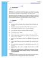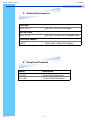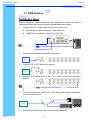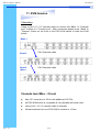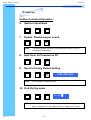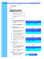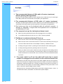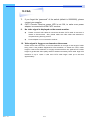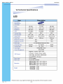
1
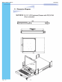
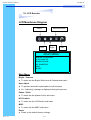
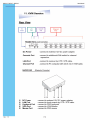
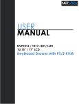
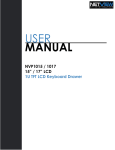
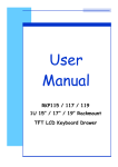
RKP215 / RKP217 / RKP219
User Manual
4. Package Contents
LCD Monitor Drawer with PS/2 KVM Switch (Two Consoles)
1 Piece
User Manual
1 Piece
DC Power Adapter
1 Piece
Power Cord
1 Piece
Mounting Bracket
1 Pair
Fasteners
4 Pieces
CD-6 3-in-1 KVM cable
8 Pieces
Before Unpacking
It is very important to locate the LCD Keyboard Drawer in a suitable environment.
●
The surface for placing and fixing the LCD Keyboard Drawer should be stable and level
or mounted into a suitable cabinet.
●
Make sure the place has good ventilation, is out of direct sunlight, away from sources of
excessive dust, dirt, heat, water, moisture and vibration.
●
Convenience for connecting the LCD Keyboard Drawer to the related facilities should be
well considers too.
Unpacking
The LCD Keyboard Drawer comes with the standard parts shown as above. Check and make
sure they are included and in good condition. If anything is missing, or damage, contact the
supplier immediately.
Rev. : 1.0
P.3
RKP215 / RKP217 / RKP219
User Manual
5. Optional Accessories
KVM Cable
CD-6 / 10 / 15
6ft / 10ft / 15ft 3-in-1 KVM cable
Cascade Cable
CA-6 / 10 / 15
6ft / 10ft / 15ft PS/2 3-to-3 Cascade cable
Conversion Adapter
SUN-31
SUN / iMAC USB to PS/2 adapter
6. Peripheral Products
Rev. : 1.0
Model
Description
CV-801
8-Port PS/2 KVM switch
CV-1601
16-Port PS/2 KVM switch
P.4
RKP215 / RKP217 / RKP219
User Manual
7. Important Safeguards
Please read all of these instructions carefully before you use the device.
Save this manual for future reference.
●
Unplug the LCD Keyboard Drawer from the power outlet before cleaning.
●
Do not spray liquid cleaners or aerosol directly on the device. Wet a cloth with
a neutral detergent (e.g. clean water) and squeeze it tight, then clean the
screen slightly with it.
●
Do not expose the LCD Keyboard Drawer directly to rain, water, moisture or
sunlight.
●
Do not attempt to service the device yourself. Improper operation may void
your warranty. Refer all servicing to qualified service personnel.
●
●
Safe storage environment of the LCD Keyboard Drawer is ranging between –
20oC and 60oC. Permanent damage could occur if the LCD Keyboard Drawer
is stored outside the safe range.
Unplug the keyboard drawer with LCD Keyboard Drawer immediately and call
a qualified service personnel under the following conditions:
1.
If the LCD Keyboard Drawer has been exposed to rain, liquid or water.
2.
If the LCD Keyboard Drawer has been dropped or the casing has been
damaged.
What the warranty does not cover
1.
Any product, on which the serial number has been defaced, modified or
removed.
2.
Damage, deterioration or malfunction resulting from:
a) Accident, misuse, neglect, fire, water, lightning, or other acts of nature,
unauthorized product modification, or failure to follow instructions supplied
with the product.
b) Repair or attempted repair by anyone not authorized by us.
c) Any damage of the product due to shipment.
d) Removal or installation of the product.
e) Causes external to the product, such as electric power fluctuation or failure.
f)
Use of supplies or parts not meeting our specifications.
g) Normal wear and tear.
h) Any other causes which does not relate to a product defect.
3. Removal, installation, and set-up service charges.
Rev. : 1.0
P.5
RKP215 / RKP217 / RKP219
User Manual
8. Structure Diagram
1.
Keyboard
2.
Aluminium front panel
3.
Class A active matrix TFT LCD panel
4.
Analog to digital signal converter board
5.
Rear metal case
6.
LCD inverter
7.
LCD membrane
8.
Ball bearing telescopic slides with stopper
9.
Adjustable mounting bracket
10. KVM membrane & KVM board
•‚
ƒ „… †
Š ‡
Rev. : 1.0
P.6
ˆ
Š
‰
RKP215 / RKP217 / RKP219
User Manual
LCD
Session
Rev. : 1.0
P.10
RKP215 / RKP217 / RKP219
User Manual
10. LCD Session
LCD Membrane Diagram
Power
Menu/Selection
Right
Left
Exit
MAIN MENU
BRIGHT/CONTRAST
AUTO ADJUST
PHASE/CLOCK
H/V POSITION
MISC
RESET
Main Menu
Bright / Contrast
●
To enter into the Bright, Black level & Contrast sub-menu
Auto Adjust
●
To perform automatic optimisations of all functions
●
An “ Adjusting” message is displayed during the process
Phase / Clock
●
To enter into the phase & clock sub menu
H/V Position
●
To enter into the H/VPosition sub-menu
MISC
●
To enter into the MISC sub-menu
Reset
● Reset to the default factory settings
Rev. : 1.0
P.11
RKP215 / RKP217 / RKP219
User Manual
10. LCD Session
Bright / Contrast
1. Brightness
●
To perform brightness adjustment of the input RGB signal
●
Use the Left & Right button to adjust and button
to “Brightness”
2. Contrast
●
To adjust the contrast level of the input signal
●
Use the Left & Right button to adjust and button
to “Contrast”
Phase / Clock
1. Phase
●
To adjust input video sampling clock’s phase
●
Use the Left & Right button to adjust and button
to “Phase”
2. Clock
●
To adjust input video sampling clock
●
Use the Left & Right button to adjust and button
to “Clock”
H/V Position
1. H.Position
●
To adjust the horizontal size of the frame
●
Use the Left & Right button to adjust and button
to “H.position”.
2. V.Position
Rev. : 1.0
●
To adjust the vertical position of the frame
●
Use the Left & Right button to adjust and button
P.12
to “V.position”.
RKP215 / RKP217 / RKP219
User Manual
10. LCD Session
MISC
1. Information
●
●
●
The first header row shows the current resolution setup
The second header row shows the horizontal frequency of the current
input signal
The third header row shows the vertical frequency of the current input
signal
2. OSD Timer
●
To modify the duration of the OSD time-out
3. Color
a) 5500K
●
Select Colour Temp at 5500K
b) 6500K
●
Select Colour Temp at 6500K
c) 9500K
●
Select Colour Temp at 9500K
d) User
●
Change Colour Temp by manual
4. Language
● To select the language of OSD menu 7 Languages :
(1) English
(2) Japanese (日本語)
(3) Chinese (中文)
(4) German
(5) Francais
(6) Espanol
(7) Italiano
Rev. : 1.0
P.13
RKP215 / RKP217 / RKP219
User Manual
10. LCD Session
Resolution Settings
For Microsoft Windows
Step 1 – Press right click on the desktop
Step 2 – Choose “Properties”
Step 3 – Change the “Screen Resolution”
Step 4 – Change the “Screen refresh rate”
Rev. : 1.0
P.14
RKP215 / RKP217 / RKP219
User Manual
10. LCD Session
Resolution Settings
For SUN Servers
●
●
●
●
●
●
●
●
Resolution configuration procedures should be run by qualified SUN
server administrator
Sun Servers are using resolution at 1152 x 900 x 76Hz.
Supported resolution mode for 15” LCD:
1024 x 768 x 70/75Hz
Supported resolution mode for 17” LCD:
1280 x 1024 x 75Hz
You need to change the Sun Server resolution before you connect to
LCD Display.
Please do the following procedures to change the resolution settings :
1. As root:
You may find the following comment “/user/sbin/m64config”.
2. To view current resolution:
Type “/user/sbin/m64config – prconf”.
3. To change to 1024x768 @ 70MHz:
Type “/user/sbin/m64config – res 1024x768x70 now”.
4. The screen will be rubbish.
5. Then type “pkill Xsun”.
And Type “pkill Xsession” to restart the Xsession.
Note :
Remember to RESTART the server after these
processes.
●
Under Common Desktop Environment (CDE).
●
To change the OpenBoot resolution, you can type the following
command in OK prompt.
1. In OK prompt, type “setenv output-device screen:r1024x768x70”.
2. Type “printenv” to confirm the resolution has been changed
to 1024x768x70Hz.
3. Then type, “reset” to restart the system.
Note : Remember to RESTART the server after these processes.
Rev. : 1.0
P.15
RKP215 / RKP217 / RKP219
User Manual
KVM
Session
Rev. : 1.0
P.16
RKP215 / RKP217 / RKP219
User Manual
11. KVM Session
Front View
Bank No.
Selected Channel
Online Channel
Channel Select Button
Bank Button
Shift Button
LED Indication
Selected Channel
- Displayed channel on monitor & red in LED.
Channel select button - Press to select channel from 1 – 8.
Rev. : 1.0
Shift button
- Press & Hold follow with a channel button
to select channel from 9 – 16.
Online Channel
- Green LED state the PC has connected
and power on.
Bank no.
- Display the Bank no. from 1 – 8.
Bank button
- Select the bank from 1 – 8 (for cascade only).
P.17
RKP215 / RKP217 / RKP219
User Manual
11. KVM Session
Installation Steps
Before installation, please make sure all computers are turned on and its
operating system are running properly with keyboard and mouse.
1.
2.
Connect the 3-in-1 KVM cable to the one of your server.
●
Mini Din 6-pin Male connector to the USB Port
●
HDDB 15-pin Male connector to the VGA Port
Plug the power adapter included to the switch.
DC
Power
3.
Connect STP / UTP cable to the switch.
Remote
Console
4.
Connect the another end of the 3-in-1 cable to the LCD Keyboard
Drawer
. . . . . . . . . . . . .
5.
Connect another end of the STP / UTP cable and mouse, keyboard &
monitor to the receiver.
Local
Console
6.
Rev. : 1.0
Reset PS/2 KVM Switch (Two Consoles) by membrane
P.19
RKP215 / RKP217 / RKP219
User Manual
11. KVM Session
Cascading
Using a CA-6 / 10 / 15 cascade cable to connect from Bank 1’s “Cascade
port” to Bank 2’s “Console port”. After connected please press “Bank” &
“Channel” button on the front of the PS/2 KVM switch to reset the KVM
switch.
Bank 1
Bank 2
Bank 8
(Max.)
CA-6 Cascade cable
CA-6 Cascade cable
Cascade level Max. : 8 level
Rev. : 1.0
●
Max. PC connection is 128 or with additional 122 PCs.
●
All PS/2 KVM switch is compatible & can cascade with each other.
●
Using CA-6 / 10 / 15 cascade cable to cascade.
●
Normal distance from one PS/2 KVM to another is 15 feet.
P.20
RKP215 / RKP217 / RKP219
User Manual
12. Start Up
1.
The channels that have PC connected and it is switch on will have a
green LED on that channel.
2.
The red LED will indicate the selected channel.
3.
7 segments LED will display the bank number.
4.
Press channel button to select the channel.
5.
Enter the password, default is “00000000” eight zeros.
6.
Otherwise the keyboard & mouse will be locked.
7.
If you forget your password, send back to Manufacturer.
HotKey Command
Rev. : 1.0
●
Simple key sequence.
●
Press “ Scroll Lock” twice within 2 seconds.
●
Follow with a beep sound, going into the hot key mode.
●
Need to key in the hot key within 2 seconds.
●
Go back to Operation System Control state.
P.21
RKP215 / RKP217 / RKP219
User Manual
12. Start Up
Hot-key Command Operation
1.
Calling OSD Menu
Scroll
2.
£
+
Scroll
+
¤
+
Switch to Previous Bank
Scroll
5.
Scroll
+
Switch to Next Power On Port (powered on PC only)
Scroll
4.
Space Bar
+
Switch to Previous Port (powered on PC only)
Scroll
3.
Scroll
+
Scroll
+
First digit of Port Number:
0 for Port 0-9
1 for Port 10-16
Pg
Up
+
Second digit of
port Number
Switch to Specific Port
Scroll
Scroll
+
Bank
1~8
+
No.
0 or 1
+
No.
0-9
+
Example :
a)
Bank 1 Port 4
Scroll
b)
Scroll
+
1
+
0
+
2
+
1
+
4
Bank 2 Port 16
Scroll
Rev. : 1.0
+
+
Scroll
+
P.22
6
RKP215 / RKP217 / RKP219
User Manual
12. Start Up
HotKey Command Operation
6.
Switch to Next Bank
Scroll
7.
+
+
Note:
PgDn
Scroll
B
+
The default Beeper function is ON and beeper control is only for
available for Scan Mode.
Auto Scan for Powered on PC
Scroll
9.
+
Enable / Disable beeper sound
Scroll
8.
Scroll
+
Scroll
S
+
Reset to factory Default Setting
Scroll
+
Note:
Scroll
R
+
ROM REFLASH
Not available for password reset.
10. Find Port by name
Scroll
Note:
Rev. : 1.0
+
Scroll
+
F
FIND:█
When the above dialogue appear, type the PC name and the OSD
Menu will search PC name starting from 1st powered on PC port.
P.23
RKP215 / RKP217 / RKP219
User Manual
12. Start Up
OSD Structure Diagram
Bank Session
BANK : 1
BANK : 1 SYSTEM 01
01
01
03
SYSTEM
01 03
®
SYSTEM
03
05
03
® SYSTEM 05
05
07
® SYSTEM 05
07
02
® SYSTEM 02
E
SYSTEM0204
02 ®®SYSTEM
04
06
06
08
® SYSTEM
SYSTEM0406
PC Session
SYSTEM
06 08
®
SYSTEM
07
® SYSTEM 08
OSD SYSTEM
: 1 0 SEC. 07
CHANGE08PASSWORD
OSD : 1 0 SEC. CHANGE
SCAN:
CONSOLEPASSWORD
ON/OFF
KVM Settings
Session
SCAN:
1 0 SEC. ENTER
CONSOLE
ON/OFF
ESC
: QUIT
:COMPLETE
ESC :: QUIT
TAB
NEXT
ENTER
:COMPLETE
INSERT
:EDIT
Menu
Information
TABSELECT
: NEXT PORT
INSERT :EDIT
á/â:
á/â: SELECTBANK
PORTSELECT
PgDn/PgUp:
PgDn/PgUp: BANK SELECT
OSD Menu Operation
Use “Tab” key to select session like Bank, PC, OSD, SCAN, CHANGE
PASSWORD, CONSOLE ON/OFF, etc…
Bank Session
Use Page Up & Page Down to switch previous or next bank
PC Session
1.
“®” next to the PC name represents the PC system is powered on
2.
Use up arrow key “á” or down arrow key “â” to select port for destination PC name and press “Enter” to select
3.
Edit PC name - Press “Ins” key for editing PC name
Note: PC name should not be more than 8 characters.
4.
Rev. : 1.0
When editing is finished press “Enter”.
P.24
RKP215 / RKP217 / RKP219
User Manual
12. Start Up
KVM Settings Session
1.
OSD
●
●
2.
●
It can be modified to 99
seconds for maximum.
Choose “Change Password” in
KVM Setting Session.
●
Key-in the existing password.
●
Enter the New Password.
●
Re-Enter the New Password.
●
Changing Password complete.
●
The steps are shown as next
picture:
Console On/OFF
●
ON – any user can use the
console
●
●
5.
Scan interval from one PC port
to next PC port when applying
auto scan, its default is 10
seconds.
Change Password
●
Default password “00000000”
8 zeros
●
4.
It can be modified from 05 – 99
seconds.
Scan
●
3.
OSD Menu on screen time
default is 10 seconds.
OFF – user is not allowed to
use the console port, unless
password is entered.
Default – OFF, you need to
key-in password.
Escape
When the following screen is
appeared, you can press
”ESC” key to escape.
ENTER PASSWORD : █
ESC : QUIT
ENTER :
ENTER NEW PASSWORD : █
ESC : QUIT ENTER : COMPLETE
RETYPE NEW PASSWORD : █
ESC : QUIT ENTER :
COMPLETE
NEW PASSWORD COMPLETE
ESC : QUIT ENTER :
COMPLETE
●
Rev. : 1.0
P.25
102
?SYSTEM 02
RKP215 / RKP217 / RKP219
User Manual
13. FAQ
1. The recommended distance of VGA cable is 5 meters (maximum)
without ghosting and degradation.
Normally, the cable length is based on driver capacity of your VGA card. If you need longer
VGA cable, please use VGA extender to accomplish your applications.
2. The recommended distance of PS/2 cable is 5 meters (maximum).
Normally, the cable length is based on driver capacity of your motherboard PS/2 port. If you
need longer PS/2 cable, please use PS/2 extender to accomplish your applications.
3. Don’t press any keys on the keyboard while the selected computer is
booting up. Otherwise, it might cause the keyboard error or keyboard is
not detected at PC side.
4. The computer boot up fine, but keyboard doesn’t work
●
Make sure the keyboard works when directly plugged into the computer.
●
Try a different keyboard, but use only 101, 102 or 104-key keyboard.
5. The Mouse is not detected during PC boot up.
6.
●
Make sure the mouse works when directly plugged into the computer.
●
Make sure the mouse is a true PS/2 mouse. A combo mouse will work just as long as
it is set for PS/2 mode with the correct adapter. Please try a different mouse.
●
Avoiding moving the mouse or pressing the mouse buttons when switching ports.
●
Avoiding switching ports during shutting down the PC process.
●
When you switch one PC port to another PC port, the best scan time setting need to
be set to 5 sec. or more. Normally, the VGA monitor change one resolution mode to
another will take one or two seconds. So, the scan time is not recommended to below
5 seconds.
The power switch is off, but the switch still works fine or power
adapter is unplugged from the switch, but the switch still works fine.
KVM Switch unit draws the power source from power adapter and all PC’s PS/2 port.
Some PC’s PS/2 port can support enough power for the switch, but some PC’s PS/2 port
(like laptop, notebook computer etc.) is unable to supply enough power for the switch. In
order to make sure the system can work steadily, please do not set power switch to off
state or remove the power adapter from the switch.
Although the PCs connected to KVM Switch unit are able to support enough power to
the stand alone switch, KVM Switch unit still needs a power adapter
Rev. : 1.0
P.26
13. FAQ
7.
If you forget the “password” of the switch (default is 00000000), please
contact your supplier.
8.
CAT.5 Console Receiver power LED is not ON, to make sure power
adapter is connected to KVM CAT.5 receiver.
9.
No video signal is displayed on the remote monitor.
●
Please check all VGA cables & connecters whether CAT.5 cable & connector is
loosed or disconnected. Also, please make sure VGA cable was attached to
computer during boot up process.
●
Power adapter is not connected to receiver.
10. Video signal is foggy or un-cleared on the screen.
Please check VGA connector, or the VGA resolution is too high for the length of cable
being used. If the problem happened at VGA resolution, to shorten the CAT.5 cable
length or reduce VGA resolution. It is highly recommended to use “optimal CAT.5 cable
length “to get the best video quality and don’t waste unnecessary CAT5 cable. High VGA
resolution is up to 1,280 x 1,024 and CAT.5 cable length could up to 500 feet
approximately.
Rev. : 1.0
P.27
RKP215 / RKP217 / RKP219
User Manual
14. Technical Specifications
KVM
Specification
Item
Local Console
CAT.5 Remote Console
PC port
16
N/A
PC Port interface
HDDB 15 pin
N/A
PS/2 Keyboard: Mini Din 6 pin Female
PC Computer
Interface
PS/2 Mouse: Mini Din 6 pin Female
N/A
VGA : HDDB 15pin Female
PS/2 Keyboard: Mini Din 6 pin Female
Cascade Port
Connector
PS/2 Mouse: Mini Din 6 pin Female
N/A
VGA: HDDB 15pin Female
KVM Cable
Connection
3-in-one HDDB 15-pin KVM Cable
(CD-6/ 10/ 15)
PC Selection
LED
N/A
On screen display menu, Hot key, Push button
1 Bank LED
1 Power LED
16 Online LED (Green)
1 Status LED (Red)
16 Selected LED (Green)
On screen display
control
Yes
Scan intervals
Keyboard and mouse
emulation
VGA resolution (Max.)
5-99 seconds
PS/2
1920 x 1440
1600 x 1200
CAT.5 cable length
(Max.)
N/A
500 feet
Bandwidth
200MHz
160MHz
Cascade Level (Max.)
8 Levels
Housing
Power Adapter
Metal
DC 12V 1A
Operation
Temperature
0~40 ℃
0~80%, Non-Condensing
Humidity
Rev. : 1.0
DC 9V 500mA
P.28