1
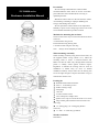
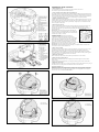
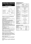
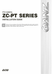
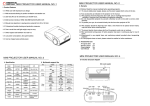
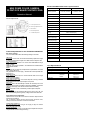
MINI DOME COLOR CAMERA
ZC-DNT4312 NHA/ZC-DNT4312 PHA
Operation Manual
ZC-DNT4312NHA/PHA camera specifications
Type / Format
Scanning Element
ZC-DNT4312NHA
ZC-DNT4312PHA
NTSC 2:1 Interlace
H:15734Hz, V:59.9Hz
PAL 2:1 Interlace
H:15625Hz, V:50Hz
Image Picture Element
1/3” Interline CCD sensor
Resolution (TV lines)
Camera adjustments
540 TVL (normal)
Minimum illumination
0.08lx @ F1.4
Exposure Control
DC Auto IRIS Lens
Flickerless
A.: Focus adjustment lever
B.: View angle adjustment lever
BLC
Central Area for DC Auto IRIS Lens
Day/Night
Burst ON/OFF & IR cut filter IN/OUT
C.: DIP switches
White Balance
D.: DC-IRIS adjustment
Auto White Balance
Range
E.: V-PHASE adjustment
MES 1/100sec (1/120)
Auto White Balance
2700°K~11000°K (normal)
2000°K~18000°K (EX.)
Sync System
Internal / Line Lock
Line Lock
(Phase Adj. Range)
Line Lock
(Frequency Range)
Video Output
Camera adjustments for the ZC-DNT4312NHA/PHA
DIP switch settings
The row of DIP switches allow the following settings to be made:
TDN mode
If this switch is set to “ON”, the camera automatically captures the image
in color when the subject is bright and in B/W when the subject is dark.
Auto White Balance
AWB: The camera operates in the normal Auto White Balance range
2700K~11000K
AWB EX: The camera operates in the extended Auto White Balance
range 2000K~18000K
SYNC
In LL mode, the V-Phase may be adjusted to compensate for connected
supply phase differences.
Only applicable for 24 VAC supply - otherwise the camera operates with
INTernal sync.
Flickerless mode
If this switch is set to “ON”, the camera reduces flicker in the image
under fluorescent lighting.
Black Light Compensation
If this switch is set to “ON”, the camera response to strong unwanted
lighting effects behind the required subject is improved.
AGC mode
Setting to “AGC” will automatically increases the sensitivity even if the
brightness of the subject is insufficient. Selecting “NORMAL” will remove
noise from the image, but it will also limit the camera’s sensitivity.
SHARP
Setting this switch to “ON” automatically creates subject sharpness.
Day and Night
The D&N mode can be activated if TDN is set to “ON”. If set to “HI”, the
time of automatically switching to Day or Night mode will be extended.
Focus & field of view adjustment
Twist the levers on the side of the vari-focal camera to adjust the focus
and field of view settings.
TIP: If necessary, perform the final focus through the dome cover,
holding it to the lens reversed to confirm the final results.
Vertical phase adjustment
Use this adjustment when using an AC supply to align the camera
phase with that of the supply.
DC-IRIS adjustment
This is factory set and should not normally require adjustment except to
compensate for excessive image blooming.
0°~270°K
60Hz ± 1Hz
50Hz ± 1Hz
1.0 Vpp 75 Ohm BNC unbalance
S/N Ratio
50dB
White Clip
120IRE
Gamma Compensation
0.45
Operation Temperature
-10°C ~ +50°C (-30°C ~ +50°C with Heater)
Storage Temperature
-20°C ~ +60°C (-35°C ~ +50°C with Heater)
Power Range
Power Consumption
DC 10.6V ~ 30V & AC 24V +/- 20%
4.2W
External Dimension
140(φ)mm x 100(H)mm
Weight
600g
Lens Specifications
Focal Length
F-No.
Iris Range
Minimum Object Distance
Angle Of View
Diagonal
Horizontal
Vertical
Lens Type
3.3~12 mm
F1.4
F1.4~F360
0.5 m
125.7°~29.9°
89.8°~23.9°
63.6°~17.9°
Aspherical
Português/Portuguese
Eliminação do seu antigo aparelho
1. Quando este símbolo de latão cruzado estiver afixado a um produto,
significa que o produto é abrangido pela Directiva Europeia 2002/96/EC.
2. Todos os produtos eléctricos e electrónicos devem ser eliminados
separadamente da coleta de lixo municipal através de pontos de recolha
designados, facilitados pelo governo ou autoridades locais.
3. A eliminação correcta do seu aparelho antigo ajuda a evitar potenciais
consequências negativas para o ambiente e para a saúde humana.
4. Para obter informaçõs mais detalhadas acerca da eliminação do seu
aparelho antigo, contacte as autoridades locais, um serviço de eliminação
de resíduos ou a loja onde comprou o produto.
English
Disposal of your old appliance
1. When this crossed-out wheeled bin symbol is attached to a product it
means the product is covered by the European Directive 2002/96/EC.
2. All electrical and electronic products should be disposed of separately from
the municipal waste stream via designated collection facilities appointed by
the government or the local authorities.
3. The correct disposal of your old appliance will help prevent potential
negative consequences for the environment and human health.
4. For more detailed information about disposal of your old appliance, please
contact your city office, waste disposal service or the shop where you
purchased the product.
Français/French
Élimination de votre ancien appareil
1. Ce symbole, représentant une poubelle sur roulettes barrée d'une croix,
signifie que le produit est couvert par la directive européenne 2002/96/EC.
2. Tous les produits électriques et électroniques doivent être éliminés
séparément de la chaîne de collecte municipale des ordures, par
l’intermédiaire des installations de collecte prescrites et désignées par le
gouvernement ou les autorités locales.
3. Une élimination conforme aux instructions aidera à réduire les
conséquences négatives et risqueséventuelspour l'environnement et la
santé humaine.
4. Pour plus d'informations concernant l'élimination de votre ancien appareil,
veuillez contacter votre mairie, le service des ordures ménagères ou encore
le magasin où vous avez acheté ce produit.
Deutsch/German
Entsorgung von Altgeräten
1. Wenn dieses Symbol eines durchgestrichenen Abfalleimers auf einem
Produkt angebracht ist, unterliegt dieses Produkt der europäischen
Richtlinie 2002/96/EC.
2. Alle Elektro- und Elektronik-Altgeräte müssen getrennt vom Hausmüll über
die dafür staatlich vorgesehenen Stellen entsorgt werden.
3. Mit der ordnungsgemäßen Entsorgung des alten Geräts vermeiden Sie
Umweltschäden und eine Gefährdung der persönlichen Gesundheit.
4. Weitere Informationen zur Entsorgung des alten Geräts erhalten Sie bei der
Stadtverwaltung, beim Entsorgungsamt oder in dem Geschäft, wo Sie das
Produkt erworben haben.
Italiano/Italian
INFORMAZIONE AGLI UTENTI
Ai sensi dell’art. 13 del Decreto Legislativo 25 luglio 2005, n. 151"Attuazione
delle direttive 2002/95/CE, 2002/96/CE e 2003/108/CE, relative alla riduzione
dell'uso di sostanze pericolose nelle apparecchiature elettriche ed elettroniche,
nonché allo smaltimento dei rifiuti"
Il simbolo del cassonetto barrato riportato sull’apparecchiatura o sulla sua
confezione indica che il prodotto alla fine della propria vita utile deve essere
raccolto separatamente dagli altri rifiuti.
La raccolta differenziata della presente apparecchiatura giunta a fine vita è
organizzata e gestita dal produttore. L’utente che vorrà disfarsi della presente
apparecchiatura dovrà quindi contattare il produttore e seguire il sistema che
questo ha adottato per consentire la raccolta separata dell'apparecchiatura
giunta a fine vita.
L’adeguata raccolta differenziata per l’avvio successivo dell’apparecchiatura
dismessa al riciclaggio, al trattamento e allo smaltimento ambientalmente
compatibile contribuisce ad evitare possibili effetti negativi sull’ambiente e sulla
salute e favorisce il reimpiego e/o il riciclo dei materiali di cui è composta
l’apparecchiatura. Lo smaltimento abusivo del prodotto da parte del detentore
comporta l’applicazione delle sanzioni amministrative previste dalla normativa
vigente.
Polski/Polish
Utylizacja starych urządzeń
1. Kiedy do produktu dołączony jest niniejszy przekreślony symbol kołowego
pojemnika na śmieci, oznacza to, że produkt jest objęty europejską
dyrektywą 2002/96/EC.
2. Wszystkie elektryczne i elektroniczne produkty powinny być utylizowane
niezależnie od odpadów miejskich, z wykorzystaniem przeznaczonych do
tego miejsc składowania wskazanych przez rząd lub miejscowe władze.
3. Właściwy sposób utylizacji starego urządzenia pomoże zapobiec
potencjalnie negatywnemu wpływowi na zdrowie i środowisko.
4. Aby uzyskać więcej informacji o sposobach utylizacji starych urządzeń,
należy skontaktować się z władzami lokalnymi, przedsiębiorstwem
zajmującym się utylizacją odpadów lub sklepem, w którym produkt został
kupiony.
Español/Spanish
Cómo deshacerse de aparatos eléctricos y electrónicos viejos
1. Si en un producto aparece el símbolo de un contenedor de basura tachado,
significa que éste se acoge a la Directiva 2002/96/EC.
2. Todos los aparatos eléctricos o electrónicos se deben desechar de forma
distinta del servicio municipal de recogida de basura, a través de puntos de
recogida designados por el gobierno o las autoridades locales.
3. La correcta recogida y tratamiento de los dispositivos inservibles contribuye
a evitar riesgos potenciales para el medio ambiente y la salud pública.
4. Para obtener más información sobre cómo deshacerse de sus aparatos
eléctricos y electrónicos viejos, póngase en contacto con su ayuntamiento,
el servicio de recogida de basuras o el establecimiento donde adquirió el
producto.
FCC INFORMATION
WARNING: This equipment has been tested and found to comply with the
limits for a Class B digital device, pursuant to Part 15 of the FCC Rules. These
limits are designed to provide reasonable protection against harmful
interference in a residential installation. This equipment generates, uses, and
can radiate radio frequency energy and, if not installed and used in
accordance with the instructions, may cause harmful interference to radio
communications. However, there is no guarantee that interference will not
occur in a particular installation. If this equipment does cause harmful
interference to radio or television reception, which can be determined by
turning the equipment off and on, the user is encouraged to try to correct the
interference by one or more of the following measures:
- Reorient or relocate the receiving antenna.
- Increase the separation between the equipment and receiver.
- Connect the equipment into an outlet on a circuit different from that to
which the receiver is connected.
- Consult the dealer or an experienced radio/television technician for help.
Any changes or modifications not expressly approved by the party responsible
for compliance could void the user's authority to operate the equipment.
This device complies with Part 15 of the FCC Rules. Operation is
subject to the following two conditions: (1) this device may not cause
harmful interference, and (2) this device must accept any interference
received, including interference that may cause undesired operation.
This Class B digital apparatus complies with Canadian ICES-003.
The CE Marking is a Directive Conformity mark of the European Union (EU).
VANDAL RESISTANT DOME CAMERA
ZC-D4000 series
Enclosure Installation Manual
Precautions
・Do not attempt to dismantle the camera module
mounted within the dome. There are no user serviceable
parts within the camera module. Refer servicing to
qualified personnel.
・Handle the camera with care. Do not abuse the camera.
Avoid striking or shaking it. Improper handling and
storage could damage the camera.
・Do not operate the camera outside of its temperature,
humidity or power source rating range. Please refer to the
environmental information provided overleaf.
Methods for mounting the enclosure
There are three main ways to mount and attach the dome
enclosure:
A: Flush mount using screws
B: Flush mount using locking arms
C: Surface mount using the outer ring
Note: Always use the template provided
When mounting externally
When mounting externally using the four base holes, use
the supplied rubber o-rings (shown in C) within the
mounting holes to ensure a moisture-resistant seal.
Make sure that the cable entry through either knockout
panels is suitably sealed against moisture ingress.
Regardless of whether the locking arms are used for
installation or folded away (in favor of another
installation method), always make sure the locking arm
screws are tight enough to compress the rubber o-rings to
maintain the moisture seal.
Packing list
Vandal Resistant Dome Enclosure
4 #12 x 1 1/2 mounting screws
4 rubber sealing o-rings
4 wall plugs
1 Torx bit
1 Camera chassis & liner
1 wire ended power adaptor lead
4 plastic screw caps to conceal the dome cover screws
1 large rubber gasket (fitted between enclosure and
outer ring)
1 ¾” sealing plug (1/2” sealing plug fitted to
enclosure)
1 ½” and 1 ¾” cable entry grommets
Weather resistance
IP66 Rated
Installing the dome enclosure
1. Remove the dome cover
Use the supplied Torx driver to loosen (but not remove) the four cover screws.
The screws are captive and will be retained in the lid.
2. Use the template to mark and prepare the mounting area
The vandal resistant dome was designed to maintain their IP and NEMA ratings independent of the
install method chosen. Therefore, all mounting access positions are sealed until they are ready to be
used. For example when surface-mounting the housing, first knock out the screw access holes that
correspond to the template marks “T1”. This can be done using a crosshead screwdriver.
3. Open the required knock-out panel
Carefully drill (or tap out) either the base knock-out (E1) or internal side knock-out (E3) to the size
required to allow cable entry. When surface mounting and using the side knock-out (E3), open the
cut out (E4) within the outer ring to the required size by cutting away excess material with a hole
cutter, sharp knife or side cutters.
4. Mount the dome enclosure
Using one of the mounting schemes discussed overleaf (methods for mounting the enclosure), fix
the dome enclosure (and outer ring, if necessary) in place. When flush mounting or surface
mounting using the outer ring, ensure that the large rubber gasket (E6) is in place under the lip of
the dome enclosure.
IMPORTANT: If the dome is being mounted externally using
the four base holes, use the supplied rubber o-rings within each
of the four mounting holes of the dome base to ensure moisture
resistant seals (see Fig. C overleaf).
5. Connect the wiring
Feed the preconnected main lead (that terminates in
connections F1 and F2) through the knock-out hole and
connect it to your video out and power in cables. A wire-ended
adaptor lead (F8) is supplied for use with power supply cables
that are not terminated with an appropriate power connector
(For 12 VDC operation: Connect the red lead to +ve and the
black lead to -ve. For 24 VAC connection, polarity is not important).
IMPORTANT: The power supply must be Class 2 certified.
IMPORTANT: If the dome is being mounted externally, use a suitable sealant around the cable
access hole to ensure a moisture resistant seal.
6. Fit the camera assembly
Connect the camera to the fly-connector (F4). For ZC-DWT4312 series camera only: also connect
the OSD lead (F6) between the camera and the middle socket of the smaller circuit board.
Place the complete camera assembly (G1) onto the three mounting pillars within the enclosure.
Note: Gimbal screws are supplied with both the housing and the camera assembly (when supplied
separately), therefore, you should have three screws left over.
7. Remove the camera liner
Lift the camera liner (H1) from the chassis (H2) to provide full access to the camera.
8. Adjust the camera position and test
Rotate and pan the camera chassis to the required position and then tighten the camera chassis
locking screws.
Note: For specific camera adjustments (i.e. focusing and settings), please see the Camera Sheet.
9. Replace the camera liner
Carefully fit the camera liner (J1) over the focused camera so that it is fully seated on the top ring of
the camera chassis (J2) and provides an unobstructed view for the camera lens.
10. Replace the dome cover
Replace the dome cover (four small internal ribs within the cover locate within four corresponding
index slots (E6) within the enclosure body; these restrict the lid to only four possible orientations
and ensure that the cover screw holes are correctly aligned). Use the supplied Torx bit to tighten
the four cover screws - DO NOT OVERTIGHTEN.