1
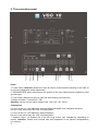
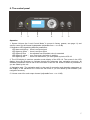
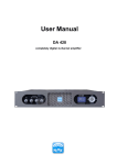
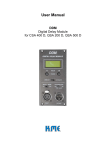
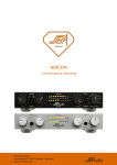
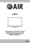
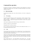
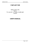
User Manual
VSS 18
SD 7
SD 8
1. Introduction
Thank you for choosing a K.M.E. product!
VERSIO has been consequently developed to portable requirements. With these compact
and ergonomic loudspeaker systems you will be able to master your reinforcement
situations in a very flexible manner (main-PA, monitoring, fill-system).
In this User Manual you will find some hints and warning notes for your new product with
which a save use of the VSS 18 is allowed. Please read this instructions before you switch
on the VSS 18 for the first time, to get in touch with particular features of your new product.
If you have questions about this product please contact the K.M.E. support.
Within our extensive production processes we only use exclusive materials and
components of best quality. Share with us the enthusiasm for good sound. The K.M.E.
team wishes you fun and success with your new PA-system!
2. Contents
1. Introduction
2. Contents ………………..…..............................................................
3. The digital system unit VSS 18
4. The delivery status ….……………………………………………........
5. The connection panel ..........……...................................….........….
6. The control panel ............…….......................................….............
7. Navigation structure on the hardware unit ....…………….………....
8. Operation ..................................................................…..................
9. Choose your factory preset - play! ...........……........…....................
10. The most important menu functions - 10.1 powering up ........…...
10.2 selecting presets ……
10.3 switching input of
channel A between
analog / digital / digital X ..
10.4 muting PA .................
10.5 entering password ....
10.6 locking your VSS 18
11. Specifications VSS 18 ..................................................................
12. Preset overview - 12.1 factory presets ..............….………….……
12.2 user presets ..............…………….............
13. Specifications SD 7 and SD 8 ...............……................................
14. PA-systems active - 14.1 Set-up PA systems ..............................
14.2 Connection shemes .............................
14.3 System versatility .................................
15. Notes ............................................................................................
16. EC-declaration of conformity ........................................................
17. Disposal of your old appliance .....................................................
2
2
3
4
5
6-8
9-11
12
12
12
13
13
14
15
16
17-20
21-22
23
24
25-29
30-31
32
35
36
3. The digital system unit VSS 18
The fully digital system unit VSS 18 with integrated 18“ subwoofer has been
consequently developed to portable requirements. With a powerful bass base and very
compact dimensions as well as the lightweight of 34 kg, the VSS 18 is also the core and
control center within the self-powered PA-systems SD 7, SD 8 and also in directional
radiating active bass arrays.
Inside work a digital 24 Bit signal processor and three powerful class D amplifiers with an
unsophisticated, crystal-clear sound quality (without conversion losses due to full digital
preamping). The analogue input signal is digitalized directly inside the input amplifier
using an intelligent 24 Bit AD-converter and remains consequently digital to the class D
amplifiers` output. The audio-DSP enables an optimal processing and controlling of the
audio signal through adjustable parameters like gain, digital cross-over, subsonic filter,
parametric EQs, peak/RMS-limiter, phase (180°) and delays. It serves also for a flexible
signal routing of the loudspeaker outputs (e.g. for top units / monitors / subwoofer).
Factory presets and user presets can be choosen, loaded and adjusted through a
navigation pad with a clear controlling sheme.
The integrated 18“ subwoofer provides a low-frequent radiation starting from 40 Hz to
160 Hz. The special tunnel geometry enables a high sound pressure with extra low
power compression and a low flow noise. The digital controlling enables a directional
(cardioid) dispersion (depending on preset) with a front-to-back damping of more than
20 dB in a wide frequency range. The subwoofer can be used in bigger production
surroundings (e.g. big indoor events) and also smaller installations.
The high-quality scratch- and impact-resistant black polyurethane coating offers optimal
road suitability. As an option you can choose a detachable and lockable roller base or
protective cover for protection. An additional protection of the loudspeaker offers the
comb-grid with acoustic foam and the special impregnation of the loudspeaker
membrane against moisture impacts.
4. The delivery status
The scope of delivery includes: 1x VSS 18, 1x PowerCon-mains cable & user manual
When you power up the VSS 18 for the very first time the following default parameters in
the main menu are pre-set:
-
preset 1 „SD 7 OMNI“ is loaded
Sig. LED threshold is adjusted to -50 dB
User LED threshold is adjusted to 0 dB (0 dB = deactivated)
output levels are shown on the LCD display
inputs switched to analogue
a password is not entered
This User Manual corresponds to the software version V1.0 r87.
It is obvious in the menu item „Diagnostics“!
3
5. The connection panel
1.
2. 3.
4.
5. 7.
7. 6.
Power
1. Power switch, Attention: please turn down all volume controls before switching on the VSS 18
to avoid an undesirable sound reproduction.
2. GROUND/FREE switch (disconnects the ground of the input channels from chassis to avoid
ground loops)
3. Fuse holder (replace fuse only by type 10A slow blowing fuse 5x20 mm)
4. Mains connector - PowerCon in / link,
Attention: use the correct mains voltage of 90 - 250 V AC / 50 - 60 Hz
Connections
5. Line in & link out - XLR balanced, analogue/digital switchable (see navigation structure);
link out is only active when the VSS 18 is powered on
6. Line in & link out - XLR balanced, always analogue;
link out is only active when the VSS 18 is powered on
7. Speaker output - 2x Speakon NL 4 (2x 500 W @ 4 Ohm (min. impedance), depending on
preset), Attention: Please mind nominal load and impedance of the passive loudspeaker(s)
you connect.
4
6. The control panel
TOP A
TOP B
← MUTE
MENU
↑Select Preset
Press 2s OK for LOCK
→
Pr 1 Versio SD7
1.
2.
3.
4.
5.
5.
Operation
1. System Volume (the “Level Control Mode” is pre-set in factory presets, see page 11) and
volume control for the internal loudspeaker (adjustable from -∞ to +6 dB)
2. Multicolour LED signalising different parameters:
LED does not light up - there is no input signal
LED lights up green - there is an input signal
LED lights up blue
- the adjusted user threshold value is exceeded
LED lights up yellow - max. input level, the limiter is working
LED lights up red
- there is a malfunction, you must power cycle the VSS 18
3. The LCD display is used as operation mode display of the VSS 18. The arrows in the LCD
display show the directions to navigate through the submenus (see navigation structure). All
software parameters must be set on the unit itself. Press the ‘OK’ button to select a parameter if
you are asked by the unit.
4. Navigation pad - The navigation pad is to be used for accessing and changing parameters on
the display of the hardware unit. Press the OK button if you are asked by the software (see
navigation structure).
5. Volume control for each output channel (adjustable from -∞ to +6 dB)
5
7. The navigation structure (menu navigation)
by means of the information on the LCD display
6
7
8
XX dB (-60 dB ... -10 dB)
XX dB (-50 dB ... 0 dB)
Sig LED Threshold
User LED Threshold
DIAG Screen
Device Settings only
All (incl. Presets)
Input 1 AD
Diagnostic
Factory Reset
System Menu
Analog
Digital
Digital X
Password
XXXXXXXX
LCD Brightness
XXX (0 ... 127)
LCD Contrast
XX (6 ... 20)
Output Levels
Operation Parameters
Display Mode
User Presets
All channels locked
Top units locked
Channel A locked
Channel B locked
Pot Lock Mode
Parts which marked by “X ” must resp. can be set with
a value. The numbers of values of the letters and
numerical value are limited. You can read out the
quantity from this sheet.
Main Menu
see Bass
see Bass
Reset Preset
XXXXX Hz (25 ... 16000 Hz)
XX dB (-12 dB ... +12 dB)
XX (0,7 ... 12,5)
XXX ms (0 ... 127 ms)
XXXX ms (0 ... 1270 ms)
XX dB (-99 dB ... 0 dB )
independent
A relative, B independent
relative
rel., lock A @ 0dB
rel., lock A+B @ 0dB
Attack Time
Release Time
Threshold
In Phase (0°)
Out of Phase (180°)
XX dB (-99 dB ... +6 dB)
Frequency
Gain
Q
Are you sure?
Level Control Mode
Out B
Out A
Limiter
Output Level
Output Phase
Equalizer 5
Type
XXX .X m (0 ... 400)
Crossover Low Cut
Subsonic 12 dB, Q =1,2
2nd Order (12 dB)
4th Order (24 dB)
Frequency
XXXX Hz (25 ... 8000 Hz)
Crossover High Cut
Type
Off
2nd Order (12 dB)
4th Order (24 dB)
Frequency
XXXX Hz (25 ... 8000 Hz)
Frequency
XXXXX Hz (25 ... 16000 Hz)
Equalizer 1
Gain
XX dB (-12 dB ... +12 dB)
Q
XX (0,7 ... 12,5)
Delay
Routing
Bass
A(a)/L(d)/R(dx)
B(a)/L(d)/R(dx)
A+B(a)/L+R(dx)
B (analog) always
Preset Name XXXXXXXXXXXX
Out A Name XXXXXX
Out B Name XXXXXX
Names
by means of the information of the menu list
8. Operation
All these components must be set directly on the hardware device.
The adjustable parameters in the submenu “user presets” for Bass / Out A / Out B are
identical.
The names of the menu points refer to the user navigation on the device.
Main Menu
•
Pot Lock Mode [to be activated by using “lock function”, see page 15]
All Channels locked [all volume pots locked]
Tops only [just lock the volume pots for Out A and Out B]
Channel A [just lock volume pot for out A]
Channel B [just lock volume pot for out B]
In this menu you can set four different „lock - functions“ for the three volume pots of the
VSS 18.
•
Sig LED Threshold
Here you set the Threshold value where the LED starts to light green when the set value is
reached by the audio signal.
•
User LED Threshold
Here you set the Threshold value where the LED starts to light blue when the set value is
reached by the audio signal.
•
Display Mode
Output Levels [output level display]
Operation Parameters [input level display and operation display]
You can chose between two layouts of the LCD graphic display. The first one shows the output
levels and the other one gives an overview about input levels and temperature of the amplifier
and PSU (PowerSupplyUnit). If the unit is muted, the operation parameter screen is displayed
automatically.
•
Diagnostics
In this menu you can read out the current software version.
•
Factory Reset
Device Settings only [Restore all adjustable parameters in the main menu]
All (incl.Presets) [Reset all changes made, incl. all user presets]
To reset the unit to the programmed initial state there are two “levels”, just to restore only the
parameters adjustable in the main menu or all menu items (incl. all user presets). After resetting
all changed settings are turned to the programmed initial state!
•
System Menu
Input 1 AD (see page 13)
Analog [switch input of channel A to analogue]
Digital [switch input of channel A to digital]
Digital X [switch input of channel A to digital X]
In this menu item you switch the input of channel A to analogue or digital or digital X. Digital X
causes a swaping of the left resp. right “audio-channel” of the digital signal on the input of
VSS 18, e.g. for the digital controlling of SD 7 and SD 8 (for the left and right side).
Password (see page 14)
In this menu item you can enter an 8-digit password. If you have enterd a password and
activate the “lock function” you must enter the password again to unlock the unit.
LCD Brightness [adjust brightness of the LCD graphic display]
LCD Contrast [adjust contrast of the LCD graphic display]
9
•
User Presets [appears only from preset no. 9 to 12]
Names
Preset Name [enter preset name, max. 12 digits]
Out A Name [enter name of output A, max. 6 digits]
Out B Name [enter name of output A, max. 6 digits]
Bass
Routing [routing of the input channels]
A(a)/L(d)/R(dx)
B(a)/R(d)/L(dx)
A+B(a)/L+R(dx)
B (analog) always
The routing of channel A and B offers four possibilities:
1. analogue (left) or digital (left) or digital crossed (right)
2. analogue (right) or digital (right) or digital crossed (left)
3. analogue (left + right) or digital (left + right)
4. input B always analogue
Delay [adjust delay, in 10 cm steps]
Crossover Low Cut (high pass) [crossover function]
Type (Subsonic-Filter 12 dB Q=1,2 or 12 dB/Oktave or 24 dB/Oktave)
Frequency
This digital filter (crossover) limits the frequency range above the adjustable crossover
frequency with a selectable slope of 12db/octave or 24 dB/octave. You can not deactivate this
digital filter. When you need a full-range audio signal on the outputs A + B you should set the
frequency to 25 Hz and choose a type of the low cut filter.
Crossover High Cut (low-pass) [crossover function]
Type (Off or 12 dB/Oktave or 24 dB/Oktave)
Frequency
This digital filter (crossover) limits the frequency range below the adjustable crossover
frequency with a selectable slope of 12db/octave or 24 dB/octave.
This filter can be deactivated (Off).
Equalizer 1 [adjust equalizer]
Frequency
Gain
Q (bandwidth)
With this digital filter (parametr. EQ) you can affect the frequency range by making adjustments
of filter frequency (center frequency), the Gain (boost resp. cut) and the Q-factor (bandwidth).
If you adjust the sensitivity (Gain) to 0 dB you deactivate this filter.
Equalizer 5 [adjust equalizer]
Frequency
Gain
Q (bandwidth)
See adjustable parameters Equalizer 1.
Output Phase [adjust output phase, you can choose between „in phase” or „out of
phase 180°”]
Output Level [adjust output level, it is independent to the adjustment of the
volume pots]
10
Limiter [adjust limiter]
Attack Time
Release Time
Threshold
This dynamic processor is working when the audio signal exceeds the entered threshold-value.
The two time constants attack and release time draw the speed of the gain regulation
mechanism and are dependent to the program material.
Out A (see adjustable parameter bass)
Out B (see adjustable parameter bass)
Level Control Mode [adjustment resp. control of output level]
independent
A relative, B independent
relative
rel., lock A @ 0dB
rel., lock A+B @ 0dB
In level control mode you define the pre-settings (dependence) of the single potentiometers
(volume controls) in relation to the output level of the different channels (Bass / Out A / Out B).
Consequently you have three possibilities:
1. All volume controls are independently adjustable from each other. (independent)
2. The volume control for Out A depends on system volume control (master), Out A is
adjustable from -∞ to +6 dB; the adjustment of Out B is independent. (A relative, B indep.)
3. The volume controls for Out A and Out B are depending on the system volume control
(master), they are adjustable from -∞ to +6 dB. (relative)
4. The volume control for Out A is pre-set by 0 dB and depends on system volume control
(master), but it is not adjustable. The volume control for Out B depends on system volume
control (master), it is adjustable from -∞ to +6 dB. (rel., lock A @ 0dB)
5. The volume control for Out A and Out B is pre-set by 0 dB and depends on system volume
control (master), but they are not adjustable. (rel., lock A+B @ 0dB)
Reset Preset
Are you sure?
Here you can reset the preset to the programmed initial state, that means you re-activate the
factory-made user preset on this memory cell and delete your preset. If you want to change one
or more menu items in a user preset, choose this topic and overwrite it with a new value and
press the OK button. Hence the new value is saved in the preset without entering all set
parameters again.
11
9. Choose your factory preset - play!
In this part of the user manual you will find a structured digest about the procedure for the
necessary settings with the main menu and its functions. If you pay attention to that
a riskless use of the VSS 18 is ensured.
10. The most important menu functions
10.1 Powering up
Switch on the VSS 18 when all volume pots are are turned fully anti-clockwise / left stop
and all connected components are switched on and muted previously to avoid an
unwanted sound reproduction.
Because the VSS 18 can be in „lock-function“ for rental purposes that means the VSS 18
may not (depending on adjustment) react on changes on the control panel and this can
cause an immediate reproduction when switching it on. Therefore it is necessary to mute
all connected devices previously.
After switching on the VSS 18 all volume pots should be turned to 0 dB (center click) with
deactivated „lock-function“ to keep a defined signal level and an optimal controlling
(this adjustment is a recommendation)
Note! During power on for the very first time Preset 1 „SD 7 OMNI“ is loaded! More
information about the initial state you can find on page 3.
10.2 Choosing presets
To control the respective system optimally the valid preset has to be load. You must
select it and load your latest PA-setup as preset on the control panel of the VSS 18.
Follow the instructions (e.g. select SD 8)!
After power on the VSS 18 for the very first time the left graphic appears on the LCD display. You
have to press the marked arrow key of the navigation pad once to select preset 2 „SD8 OMNI“
and confirm with the OK-key. In this case this procedure has to be done once again on the
second VSS 18 of the SD8.
If you control your PA system with an analogue audio signal, you can start now!
12
10.3 Switching input of channel A between analog / digital / digital X
If you want to control your PA system with a digital signal you have to switch the input of
channel A to „digital“ resp. “digital X” (see page 9). In the programmed initial state all
inputs are switched to „analogue“.
1.
2.
3.
4.
5.
6.
7.
8.
9.
10.
Press the marked arrow keys of the navigation-pad one after another (like shown in the scheme),
to switch the input of channel A to „analogue“ / „digital“ resp. „digital X” (the selection can be
looked up from the LCD display from the respective direction of arrow). After the correct selection
of the input of channel A press the OK-button and leave the menu with the left arrow key.
10.4 The „Mute- function”
This function enables to mute the PA system with just one touch of a button.
Press for 1 second the marked arrow key of the navigation pad to mute the PA system.
A repeated pressing of this arrow key causes the deactivation of the mute-function (see display).
13
10.5 Entering password
You can lock the VSS 18 with or without a password. To lock the VSS 18 with a
password (max. 8 digits) you have to enter it first. This password can be changed
every time.
Note! Keep in mind resp. note down the entered password because if you want to
„unlock“ your VSS 18 you have to enter the password again (see next page). Should you
have forgotten the password, you have no possibility to re-activate the VSS 18. Please
contact the K.M.E. support! Should the entered password had been cleared, e.g. after a
rental, you have to assume a manipulation. Follow now the instructions to activate the
menu point!
1.
2.
3.
4.
5.
6.
7.
8.
9.
10.
11.
Press the marked arrow keys of the navigation pad one after another (like shown in the scheme)
to open the sub menu „password“. Now you can enter your password with the arrow keys and
confirm with OK. You can leave the menu by pressing the left arrow key.
14
10.6 The „Lock-function“
To lock your VSS 18 (with or without password) please do the following instructions:
Set all required parameters (also the volume controls) and press, like shown in the
graphics, the OK button for 2 seconds and your system is locked (now your VSS 18 is
ready for a rental, for example). When switching it off and on again the “lock-function” is
re-activated. That means you can not change any settings (depending on settings before)
while the “lock-function” is activated. To deactivate the “lock-function” you have to press
the OK button again for 2 seconds and, if entered before, enter your password by using
the arrow keys and confirm with OK.
Attention! If you have changed the position of the volume controls during the VSS 18
was locked you will be informed on the LCD display. Now you have two possibilities to
unlock the VSS 18: after entering your password (if entered before) you can press the
OK button for two times and the VSS 18 is playing in the current adjustment of the
volume controls or you press the OK button only once and turn the volume control(s) to
the previous position(s).
←
←
15
11. Specifications VSS 18
Speaker:
Components
18“ Neodymium
Dispersion
omnidirectional / directional, depending on preset
Frequency range
38 Hz – 160 Hz (fx), depending on preset
SPL nominal
102 dB
SPL maximal
129 dB
Electronic:
Amplifiers
three fully digital amplifiers with high efficiency, about 90 %
Power output RMS
750 W bass + 2 x 500 @ 4 Ohm
Features
ground-free, navigation pad, LCD- display, adjustable digital
crossovers (80 Hz - 160 Hz), subsonic- filter, parametrical EQ’s,
peak/RMS- limiter, phase (180°), delays (0 - 1000 ms), signal-router
Protective circuits
short circuit, overload, temperature, DC on output
Connectors
analogue: line-in 2 x XLR, line-out 2 x XLR,
digital: AES/EBU input & output (XLR),
speaker out 2 x Speakon NL 4 Neutrik
Power requirements
90 - 250 Volt / 50 - 60 Hz PowerCon in /-link
Power consumption
max. 1750 W
Control panel
navigation pad, LCD display, multicolor LED, 3 potentiometer
Processor:
DSP
24 bit, 48 MHz clock
Unit delay
< 1,5 ms
Sampling
24 bit
Digital input & output
AES/EBU / S/PDIF with format/sample rate converter
(max. 192 KHz)
Preset memory
8 factory presets, 4 user presets
Finish
PU coating black
Special features
2 side-mounted handles, M20 fixing plate, stacking elements
Dimensions in mm
(B x H x T)
520 x 610 x 615
Weight
34 kg
Recommended units
top units / monitors: VL 8, VL 12, VL 15, passive subwoofer: VB 18
Optional accessory
protective cover (no. 2-311-058),
roller base (no. 1-915-004)
16
12. General view about presets
Currently the VSS 18 includes eight factory presets and four useful adjusted user
presets. When switching on for the first time preset 1 “SD 7 OMNI” is loaded (a factory
preset). You can load factory presets and change them. How it can be made you will find
on page 9 – 11 in this manual. The menu item „Userpresets“ appears only from preset
no. 9 to 12, where you can set and adjust the parameters like limiter, EQs, delays for the
outputs.
The names of the presets (listed below) refer to the menu navigation of the device.
Factorypresets:
Userpresets:
Preset 01 „SD7 OMNI“
Preset 02 „SD8 OMNI”
Preset 03 „CARDIOID 1”
Preset 04 „CARDIOID 2”
Preset 05 „CARDIOID 3”
Preset 06 „SINGLE BASS”
Preset 07 „TOPS ONLY”
Preset 08 „BASS ARRAY”
Preset 09 „USER SMALLPA”
Preset 10 „USER PA+DLY”
Preset 11 „USER BSM 1”
Preset 12 „USER BSM 2”
12.1 Factory presets - are not adjustable and erasable
Preset 1: SD7 OMNI
omnidirectional
dispersion of
the subwoofers:
90°
120°
60°
150°
180°
for
passive
top units
for
top units
30°
back
front
0°
330°
210°
300°
240°
270°
2x VSS 18 + 2x VB 18 + 2x VL 750:
analogue or digital audio signal each to input A of the VSS 18 & link it through the top units
(e.g. with a dual-cable from K.M.E., includes audio signal & power supply);
Out A is the speaker output for the passive subwoofer VB 18, Out B can be chosen as speaker
output for a passive top unit (crossover frequency 120 Hz)
17
Preset 2: SD8 OMNI
omnidirectional
dispersion of
the subwoofers:
90°
120°
60°
150°
30°
back
180°
front
0°
330°
210°
300°
240°
270°
2x VSS 18 + 4x VB 18 + 2x VL 760:
analogue or digital audio signal each to input A of the VSS 18 & link it through the top units
(e.g. with a dual-cable from K.M.E., includes audio signal & power supply);
Out A + Out B are the speaker outputs for the passive subwoofers VB 18
Preset 3: CARDIOID 1
directional
dispersion of
the subwoofers:
90°
120°
60°
150°
180°
for
passive
top unit
for
passive
top unit
30°
back
front
0°
330°
210°
300°
240°
270°
2x VSS 18 + 2x VB 18 + 2x VL 750 or VL 760:
analogue or digital audio signal each to input A of the VSS 18 & link it through the top units
(e.g. with a dual-cable from K.M.E., includes audio signal & power supply);
Out A is the speaker output for the rear channel (passive subwoofer VB 18), Out B can be chosen
as speaker output for a passive top unit (crossover frequency 120 Hz)
18
Preset 4: CARDIOID 2
directional
dispersion of
the subwoofers:
90°
120°
60°
150°
30°
back
180°
front
0°
330°
210°
300°
240°
270°
2x VSS 18 + 4x VB 18 + 2x VL 750 or VL 760:
analogue or digital audio signal each to input A of the VSS 18 & link it through the top units
(e.g. with a dual-cable from K.M.E., includes audio signal & power supply);
Out A is the speaker output for the rear channel (passive subwoofer VB 18), Out B is the speaker
output for the front channel (passive subwoofer VB 18)
Preset 5: CARDIOID 3
directional
dispersion of
the subwoofers:
90°
120°
60°
150°
180°
30°
back
front
0°
330°
210°
300°
240°
270°
2x VSS 18 + 4x VB 18 + 2x VL 750 or VL 760:
analogue or digital audio signal each to input A of the VSS 18 & link it through the top units
(e.g. with a dual-cable from K.M.E., includes audio signal & power supply);
Out A is the speaker output for the rear channel (passive subwoofer VB 18), Out B is the speaker
output for the front channel (passive subwoofer VB 18)
19
Preset 6: SINGLE BASS
1x VSS 18 (speaker outputs are inactive):
analogue audio signal to input A + B or digital audio signal to input A, only the system volume
control is active
Preset 7: TOPS ONLY
2x top units full-range (bass is inactive):
analogue audio signal to input A + B or digital audio signal to input A, the volume control for
„Out A“ + „Out B“ depending on system volume control, speaker outputs „Out A“ + „Out B“ are for
passive top units (min. 4 ohm @ 500 Watt)
Preset 8: BASS ARRAY
1x VSS 18 + 2x VB 18:
analogue audio signal to input A + B or digital audio signal to input A, the volume control for
„Out A“ + „Out B“ depending on system volume control, speaker outputs „Out A“ + „Out B“ are for
passive subwoofers VB 18 (min. 4 ohm @ 500 Watt)
20
12.2 User presets - are adjustable and programmable
These user presets are always saved in the background. So you can set your own
presets or adjust the presets 9 -12 and save in the respective presets. Your presets you
can delete separately (by the command “Reset Preset”, see menu navigation) to restore
the initial state resp. to overwrite it. When you will use those presets like shown the
graphics, please make sure that the presets are not changed! Otherwise choose the
command “Reset Preset”.
Preset 9: USER SMALLPA
Preset 10: USER PA+DLY
e.g.
monitor,
delay line,
bass
1x VSS 18 + 2x VL 12
you can set-up your audio inputs &
speaker outputs
e.g.
monitor,
delay line,
bass
2x VSS 18 + 2x VL 12
you can set-up your audio inputs &
speaker outputs
Preset 11: USER BMS 1
LS L
C LFE
R RS
21
3x VSS 18 + 1x VB 18 + 5x top units (audio inputs & speaker outputs are free configurable).
Bass management system for smaller surround systems (5.1). The VSS 18 for the center channel
and LFE-channel (low frequency enhancement) is used with this preset. You can connect an
additional bass VB 18 on the speaker output B. The VSS 18 for the L/LS and R/RS are used with
the presets no. 9.
Preset 12: USER BMS 2
L
LS LFE
C
R
RS
5 x VSS 18 + max. 14x top units (audio inputs & speaker outputs are free configurable).
Bass management system for larger surround systems (5.1, extendable) using several
loudspeakers for all channels, for example like cinemas and multimedia installations. All VSS 18
are used with this preset.
22
13. Specifications SD 7 and SD 8
The active 3-way full-range PA-systems SD 7 and SD 8 are professional and powerful
PA-systems with extraordinarily compact design and a brilliant sound. The different
formats / combinations of the VERSIO PA systems are the functional answer to a
multiplicity of tasks in mobile use as well as in the area of installation. Simple speech
reproduction, fill or delay-systems, presentations, music reinforcement with or without
subwoofers as main PA, supported by a versatile accessory assortment enable an
accurately to the respective requirements adapted solution. Due to the audio-DSP
extensive solutions are available for various using possibilities. The extension of these
PA-systems is always possible.
SD 7
SD 8
Components
2 x VL 750 (12“+1“),
2 x VSS 18 (18“),
2 x VB 18 (18”) 4 Ohm
2 x VL 760 (15“+1“),
2 x VSS 18 (18“),
4 x VB 18 (18”) 4 Ohm
Power output
total: 4000 W RMS
(2 x 500 W RMS @
4 Ohm free configurable)
total: 5000 W RMS
Frequency range
38 Hz – 19 KHz
38 Hz – 19 KHz
Connectors
audio signal:
2x line-in XLR & line-out XLR
(analogue and / or digital),
power requirements:
PowerCon 90 - 250 Volt / 50 - 60 Hz,
speaker outputs on VSS 18:
each 2x Speakon NL 4 (1+/1-)
audio signal:
2x line-in XLR & line-out XLR
(analogue or digital),
power requirements:
PowerCon 90 - 250 Volt / 50 - 60 Hz,
speaker outputs on VSS 18:
each 2x Speakon NL 4 (1+/1-)
Weight of
components
top active:
2x 21,5 kg
bass active: 2x 34 kg
bass passive: 2x 27 kg
top active:
2x 25,5 kg
bass active: 2x 34 kg
bass passive: 2x 27 kg
Recommended for
professional bands, DJs, renters
professional bands, DJs, renters
Optional
accessories
Plug & Play Pack
(no. 2-521-011),
Cover Pack
(no. 2-312-019)
Plug & Play Pack
(no.2-521-012),
Cover Pack
(no.2-312-020)
23
14. PA systems active: Set-up, connection shemes & system versatility
14.1 Set-up PA systems
Note!
Please note specific and useful set-up of a first-class loudspeaker system. A universal
statement about the correct (standard)-adjustment and set-up of PA systems is
impossible, because each reinforcement is bound to a different place and has always
different features.
When using high stands or distance rods for top parts the user has to guarantee the
stability. Please use just certified mounting material when installing the systems to
guarantee the safety. Depending on the features of the area/room to be reinforced the
top unit(s) can also be swiveled a bit horizontally and tilted vertically to reduce reflections
(on walls + ceilings) and interferences and therefore achieving a better utilization of the
sound energy.
If covers are opened or sections of casing are removed, except where this can be done
manually, live parts can become exposed. If it is necessary to open the unit this must be
insulated from all power sources.
Please mind that it is not coming to a ground loop during cabling of the system. If it
comes to deep-frequent hum switch the Ground-Free to „Free“. Always use balanced
signal cables if possible. Do not mask or detach the conducter connection on the mains
plug! Danger!
High loudspeaker levels can cause permanent hearing damage. You should therefore
avoid the direct vicinity of loudspeakers operating at high levels. Wear hearing protection
if continuously exposed to high levels.
When should I choose a directional or omnidirectional dispersion in the low-frequency
range?
Each direct radiating subwoofer has a omnidirectional dispersion in the low-frequency range.
Depending on local conditions it can comes to spatial interferences. The cardioid dispersion
pattern resulting from this approach avoids unwanted energy behind the system that greatly
reduces the reverberant field at low frequencies and provides the greatest accuracy of low
frequency reproduction.
The directional (cardioid) dispersion offers a lot of significant advantages in the all-day
reinforcement work. The highest sound energy will be radiated just in the front very
homogeneously, on the side the damping increases and achieves on the rear side a very widerange excellent damping quality at all frequency range of more than 20 dB. For the first time the
whole frequency band from bass to mid/high can be adjusted to the audiences’ area. Especially
in an acoustical different location like marquees, glas buildings, open airs with level restriction or
in halls with large reverberation time the cardioid technology is an advantage. Even at very high
volume levels develop considerably less wall- and ceiling-reflection. The complete bass
reproduction explicitly gains in pressure and precision.
24
14.2 Connection shemes
SD7 OMNI (VSS 18 preset no. 1 & VL 750 preset no. 1)
dual
cable
Out A
for passive
sub
dual
cable
Out B
audio input
right
Out A
for passive
sub
Out B
audio input
left
SD 7 consists of: 2x VSS 18 + 2x VB 18 + 2x VL 750
1. Set-up PA: - place a VSS 18 to the left and right side in front of the audience
(on solid underground)
- place a VB 18 each on a VSS 18 or directly next to a VSS 18 (front in line)
- place the top units each on a distance rod on the VSS 18 or each on a high
stand (front in line)
2. Connection: - apply power supply connection always with the supplied PowerCon cable on
VSS 18 + VL 750 on one 16A fused electric circuit
- plug in the left + right audio signal (XLR cable) each on channel A on the
VSS 18, after this you have to link each audio signal with a XLR cable to the
top units (e.g. with a dual-cable from K.M.E., which includes the audio signal
and the power supply)
- connect the speaker output „Out A“ of VSS 18 each with a passive subwoofer
VB 18 with a Speakon cable (in this preset the speaker output „Out B“ is
configured for a passive top unit – crossover frequency 120 Hz)
- switch on the system components successively, Note! please turn down all
volume controls before switching on the system components to avoid an
undesirable sound reproduction, because the system components can start
in the “lock-function” (depending on adjustment), that means it may not react on
changes on the control panel
- after switching on the system components it is advisable to set the volume knobs
to „central click“ (=0dB) to have a defined volume level
- the volume controls for „Out A” and „Out B” are depending on the system volume
control (master), they are adjustable from -∞ to +6 dB
25
SD8 OMNI (VSS 18 preset no. 2 & VL 760 preset no. 1)
Out B
for passive
sub
dual
cable
Out A
for passive
sub
Out B
for passive
sub
dual
cable
Out A
for passive
sub
audio input
right
SD 8 consists of: 2x VSS 18 + 4x VB 18 + 2x VL 760
1. Set-up PA: - place a VSS 18 to the left and right side in front of the audience
(on solid underground)
- place two VB 18 each on a VSS 18 or place all subwoofers in front of the
audience in a constantly distance (front in line)
- place the top units each on a distance rod on the VSS 18 or each on a high
stand (front in line)
2. Connection: - apply power supply connection always with the supplied PowerCon cable on
VSS 18 + VL 760 on one 16A fused electric circuit
- plug in the left + right audio signal (XLR cable) each on channel A on the
VSS 18, after this you have to link each audio signal with a XLR cable to the
top units (e.g. with a dual-cable from K.M.E., which includes the audio signal
and the power supply)
- connect the speaker outputs „Out A & Out B“ of VSS 18 each with a passive
subwoofer VB 18 with a Speakon cable
- switch on the system components successively, Note! please turn down all
volume controls before switching on the system components to avoid an
undesirable sound reproduction, because the system components can start
in the “lock-function” (depending on adjustment), that means it may not react on
changes on the control panel
- after switching on the system components it is advisable to set the volume knobs
to „central click“ (=0dB) to have a defined volume level
- the volume controls for „Out A” and „Out B” are depending on the system volume
control (master), they are adjustable from -∞ to +6 dB
26
CARDIOID 1 (VSS 18 preset no. 3 & VL 750 / VL 760 preset no. 1)
dual
cable
dual
cable
Out A
for rear sub
VB 18
Out A
for rear sub
VB 18
Setup consists of: 2x VSS 18 + 2x VB 18 + 2x VL 750 or VL 760
1. Set-up PA: - place a VSS 18 to the left and right side in front of the audience
(on solid underground)
- place a VB 18 each behind of the VSS 18 in a distance of 24 cm; Note! please
mind the distance of 60 cm to the systems among each other and the distance to
the periphery (e.g. front of stage, walls)
- place the top units each on a distance rod on the VSS 18 or each on a high
stand (front in line)
2. Connection: - apply power supply connection always with the supplied PowerCon cable on
VSS 18 + VL 750 or VL 760 on one 16A fused electric circuit
- plug in the left + right audio signal (XLR cable) each on channel A on the
VSS 18, after this you have to link each audio signal with a XLR cable to the
top units (e.g. with a dual-cable from K.M.E., which includes the audio signal
and the power supply)
- connect the speaker output „Out A“ of VSS 18 each with a passive subwoofer
VB 18 with a Speakon cable (in this preset the speaker output „Out B“ is
configured for a passive top unit – crossover frequency 120 Hz)
- switch on the system components successively, Note! please turn down all
volume controls before switching on the system components to avoid an
undesirable sound reproduction, because the system components can start
in the “lock-function” (depending on adjustment), that means it may not react on
changes on the control panel
- after switching on the system components it is advisable to set the volume knobs
to „central click“ (=0dB) to have a defined volume level
- the volume control for „Out A“ is pre-set by 0 dB and and depends on system
volume control (master), but it is not adjustable; the volume control for „Out B”
depends on system volume control (master), it is adjustable from -∞ to +6 dB
27
CARDIOID 2 (VSS 18 preset no. 4 & VL 750 / VL 760 preset no. 1)
Out A
for rear
sub VB 18
Out B for front sub VB 18
dual
cable
Out A
for rear
sub VB 18
dual
cable
Out B for front sub VB 18
Setup consists of: 2x VSS 18 + 4x VB 18 + 2x VL 750 or VL 760
1. Set-up PA: - place a VSS 18 to the left and right side in front of the audience
(on solid underground)
- place one VB 18 to the front and one backwards next to VSS 18 (side by side
and front in line, see drawing); Note! Please mind the distance of 60 cm to the
systems among each other and the distance to the periphery (e.g. front of stage,
walls)
- place the top units each on a distance rod on the VB 18 in the mid-position or
each on a high stand (front in line)
2. Connection: - apply power supply connection always with the supplied PowerCon cable on
VSS 18 + VL 750 or VL 760 on one 16A fused electric circuit
- plug in the left + right audio signal (XLR cable) each on channel A on the
VSS 18, after this you have to link each audio signal with a XLR cable to the
top units (e.g. with a dual-cable from K.M.E., which includes the audio signal
and the power supply)
- connect the speaker output „Out A“ of VSS 18 each with a passive subwoofer
VB 18 with a Speakon cable for the rear channel and speaker output „Out B“
each with a passive subwoofer VB 18 for the front channel
- switch on the system components successively, Note! please turn down all
volume controls before switching on the system components to avoid an
undesirable sound reproduction, because the system components can start
in the “lock-function” (depending on adjustment), that means it may not react on
changes on the control panel
- after switching on the system components it is advisable to set the volume knobs
to „central click“ (=0dB) to have a defined volume level
- The volume control for „Out A” and „Out B” is pre-set by 0 dB and depends on
system volume control (master), but they are not adjustable
28
CARDIOID 3 (VSS 18 preset no. 5 & VL 750 / VL 760 preset no. 1)
dual
cable
Out A
for rear
sub VB 18
dual
cable
Out B
for front
sub VB 18
Out A
for rear
sub VB 18
Out B
for front
sub VB 18
Setup consists of: 2x VSS 18 + 4x VB 18 + 2x VL 750 or VL 760
1. Set-up PA: - place a VSS 18 to the left and right side in front of the audience
(on solid underground)
- place one VB 18 to the front and one backwards on each VSS 18 (see drawing);
Note! Please mind the distance of 60 cm to the systems among each other and
the distance to the periphery (e.g. front of stage, walls)
- place the top units each on top on VB 18 or on a high stand (front in line)
2. Connection: - apply power supply connection always with the supplied PowerCon cable on
VSS 18 + VL 750 or VL 760 on one 16A fused electric circuit
- plug in the left + right audio signal (XLR cable) each on channel A on the
VSS 18, after this you have to link each audio signal with a XLR cable to the
top units (e.g. with a dual-cable from K.M.E., which includes the audio signal
and the power supply)
- connect the speaker output „Out A“ of VSS 18 each with a passive subwoofer
VB 18 with a Speakon cable for the rear channel and speaker output „Out B“
each with a passive subwoofer VB 18 for the front channel
- switch on the system components successively, Note! please turn down all
volume controls before switching on the system components to avoid an
undesirable sound reproduction, because the system components can start
in the “lock-function” (depending on adjustment), that means it may not react on
changes on the control panel
- after switching on the system components it is advisable to set the volume knobs
to „central click“ (=0dB) to have a defined volume level
- The volume control for „Out A” and „Out B” is pre-set by 0 dB and depends on
system volume control (master), but they are not adjustable
29
14.3 System versatility
This overview shows you examples of using, combination and extension of the active
system components (with passive system components) to adapt your reinforcement
optimally on your audience.
full-range setup
basis setup
2x VL 750 or VL 760
2x VL 750 or VL 760 + 2x VSS 18 + 4x 500 watts
speaker outputs (e.g. free routable as top
extension, delay line, monitoring, subwoofer)
monitor Setup
standard setup
2x VL 750 or VL 760 + 2x VSS 18 +
max. 8 monitors (VL 8 / VL 12 / VL 15)
2x VL 750 or VL 760 + 2x VSS 18 + 2x VB 18 +
max. 4 monitors (VL 8 / VL 12 / VL 15)
extended setup
2x VL 750 or VL 760 + 2x VSS 18 + 4x VB 18
30
cardioid setup 1
cardioid setup 2
2x VL 750 or VL 760 + 2x VSS 18 +
2x VB 18 + 2x 500 watts speaker
outputs ((e.g. free routable as top
extension, delay line, monitoring,
subwoofer)
2x VL 750 or VL 760 + 2x VSS 18 + 4x VB 18
cardioid setup 3
2x VL 750 or VL 760 + 2x VSS 18 + 4x VB 18
31
For your notes
32
33
34
Warranty claims please learn from the warranty card included.
You will find the User Manual of the VERSIO-Series in an other manual or on K.M.E.`s
website at www.kme-sound.com.
35
Deutsch
Entsorgung von Altgeräten
1. Wenn dieses Symbol eines durchgestrichenen Abfalleimers auf einem
Produkt angebracht ist, unterliegt dieses Produkt der europäischen Richtlinie
2002/96/EC.
Klingenthaler
Musikelektronik GmbH
Auerbacher Straße 268
08248 Klingenthal Germany
phone +49(0)37467 558-0
www.kme-sound.com
2. Alle Elektronik-Altgeräte müssen getrennt vom Hausmüll über dafür
staatlich vorgesehene Stellen entsorgt werden.
3. Mit der ordnungsgemäßen Entsorgung des alten Gerätes vermeiden Sie
Umweltschäden und eine Gefährdung der persönlichen Gesundheit.
4. Weitere Informationen zur Entsorgung des alten Gerätes erhalten Sie bei
der Stadtverwaltung, beim Entsorgungsamt oder in dem Geschäft, wo Sie das
Produkt erworben haben.
English
Disposal of your old appliance
1. When this crossed-out wheeled bin symbol is attached to a product it
means the product is covered by the European Directive 2002/96/EC.
2. All electrical and electronic products should be disposed of a separately
from the municipal waste stream via designated collection facilities appointed
by the government of the local authorities.
3. The correct disposal of your old appliance will help prevent potential
negative consequences for the environment and human health.
4. For more detailed information about disposal of your old appliance, please
contact your city office, waste disposal service or shop where you purchased
the product.
Klingenthaler Musikelektronik GmbH
Auerbacher Straße 268
08248 Klingenthal
Germany
phone +49 (0) 37467-558-0
fax +49 (0) 37467-558-33
[email protected]
www.kme-sound.com
Technical State April 2009.
The content corresponds to the state at printing. Subject to technical alterations. Misprints and errors expected.
36