1
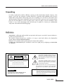
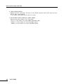
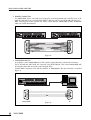
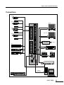
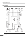
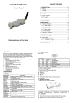
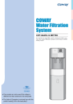
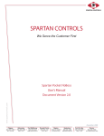
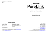
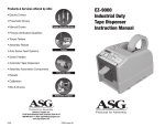
VAMS-0808 Video Audio Matrix Switcher
VAMS 0808 VIDEO AUDIO MATRIX SWITCHER
VIDEO INPUT
OUTPUT
POWER
1
OUTPUT
1
2
3
4
5
6
7
8
2
3
4
5
6
7
8
ON
INPUT
OFF
AUDIO INPUT
ALL
OFF
A/V
VIDEO
AUDIO
LOCK
Contents
1. Unpacking ............................................................................................................................1
2. Definition ..............................................................................................................................1
3. Features ................................................................................................................................2
4. Front Panel Controls...............................................................................................................3
5. Rear Panel Controls ...............................................................................................................5
6. RS-232C Operation................................................................................................................7
7. Installation ............................................................................................................................7
8. Using the Matrix ....................................................................................................................8
9. Connections.........................................................................................................................11
10. Block Diagram...................................................................................................................12
11. Specifications.....................................................................................................................13
OFFICE :
226-9 DUGJUNG - LI, HOE CHUN - EUB,
YANGJU - KUN, KYUNGKI - DO, KOREA
TEL : 82-31-860-7041~8, FAX : 82-31-858-1907
Home Page : http://www.inter-m.com
E-mail : [email protected]
VIDEO AUDIO MATRIX SWITCHER
Unpacking
ItIt isis neither
neither complicated
complicated to
to install
install nor
nor difficult
difficult to
to operate
operate your
your Video
Video Audio
Audio Matrix
Matrix Switcher.
Switcher. However,
However, aa few
few
minutes
minutes of
of your
your time
time are
are required
required to
to read
read this
this manual
manual for
for aa properly
properly wired
wired installation
installation and
and to
to become
become
familiar
familiar with
with its
its many
many features.
features. Please
Please take
take great
great care
care in
in unpacking
unpacking your
your set
set and
and do
do not
not discard
discard the
the carton
carton
and
and other
other packing.
packing. They
They may
may be
be needed
needed ifif itit ever
ever becomes
becomes necessary
necessary to
to return
return your
your set
set for
for servicing.
servicing. Never
Never
place
the
unit
near
radiators,
in
front
of
heating
vents,
in
direct
sun
light,
in
excessive
humidity
or
place the unit near radiators, in front of heating vents, in direct sun light, in excessive humidity or dusty
dusty
locations
locations so
so as
as to
to avoid
avoid early
early damage
damage and
and to
to provide
provide years
years of
of quality
quality use.
use. Connect
Connect your
your complimentary
complimentary
components
components as
as illustrated
illustrated in
in the
the following
following pages.
pages.
Definition
VAMS-0808 is a full matrix switcher which can represent 8 A/V inputs to any 8 A/V outputs simultaneously without any A/V thermal noise.
This machine includes microprocessor controller, so it’s easy to control and it allows to be displayed the
present setting at STATUS WINDOW DISPLAY.
Besides PC can control the matrix system by RS-232 communication interface.
In addition two VAMS-0808 may be cascaded for control via a signal port by configuring one VAMS-0808
as a MASTER.
CAUTION
RISK OF ELECTRIC SHOCK
DO NOT OPEN
CAUTION: TO REDUCE THE RISK OF ELECTRIC SHOCK.
DO NOT REMOVE COVER (OR BACK).
This symbol is intended to alert the user to the
presence of uninsulated “dangerous voltage”
within the product’s enclosure that may be of sufficient magnitude to constitute a risk of electric
shock to persons.
This symbol is intended to alert the user to the
presence of important operation and maintenance (servicing) instructions in the literature
accompanying the appliance.
NO USER-SERVICEABLE PARTS INSIDE.
REFER SERVICING TO QUALIFIED SERVICE PERSONNEL.
WARNING
To prevent fire or shock hazard, do not
expose the unit to rain or moisture.
Caution: To prevent electric shock do not use this (polarized) plug
with an extension cord, receptacle or other outlet unless
the blades can be fully inserted to prevent blade exposure.
Attentions: Pour prévenir les chocs électriques ne pas utiliser cette
fiche polarisée avec un prolongateur, une prise de
courant on une autre sortie de courant, sauf si les
lames peuvent étre insérées à fond sans en laisser
aucune partie à découvert.
VAMS-0808
1
VIDEO AUDIO MATRIX SWITCHER
Features
- 8 8 A/V matrix switcher.
- Simple and simultaneous output and disconnection function.
- Audio/Video random control function.
- Low crosstalk and wideband frequency response.
- Parallel connection.
- RS-232C interface.
- Restore to the first setup mode in case of power failure.
- Vertical interval switching function with GENLOCK in channel changing.
- Lock function for protecting a configuration from user’s mishanding.
2
VAMS-0808
VIDEO AUDIO MATRIX SWITCHER
Front Panel Controls
1
VAMS 0808 VIDEO AUDIO MATRIX SWITCHER
VIDEO INPUT
OUTPUT
POWER
1
OUTPUT
1
2
3
4
5
6
7
2
3
4
5
6
7
8
ON
8
INPUT
OFF
AUDIO INPUT
7
8
ALL
4
5
OFF
A/V
VIDEO
9
AUDIO
LOCK
6
3
2
1. POWER SWITCH
Power ON/OFF switch.
2. OUTPUT SELECT SWITCH
Selects output channel. When this button is pressed, the status of the selected channel is blinked. During
the blinking select any input channels, then the status of display is changed as the selected input channel
and the blinking is stopped. If the selection doesn’t exist for 10 seconds approximately, the selection is
cancelled.
3. INPUT SELECT SWITCH
Represents the selected input channel to each output channel.
4. ALL SWITCH
Selects all output channels. Press this button, and the status display of all channels are blinked. If the
selection doesn’t exist for 10 seconds approximately, the selection is cancelled. This function is very
useful when one input is displayed to all outputs or when user wants to disconnect all outputs.
5. OFF SWITCH
This button disconnects an output channel. If user press this button after select the OUTPUT SELECTING
BUTTON, the selected status display indicate “0” and the output is nothing.
6. LOCK SWITCH
Switch for protecting a configuration from mishanding. After the setting is completed, press this button 5
times then the light of this switch is blinked and all buttons can’t be controlled.
If user want to cancel this function, just press this button 5 times then the light is off.
Lock function isn’t cancelled even if this machine is on and off.
7. STATUS DISPLAY (VIDEO)
Displays the video configuration. The figure of status display represents which video inputs are transferred to video output terminals.
“1~8” indicate each channel and “0” means non output.
VAMS-0808
3
VIDEO AUDIO MATRIX SWITCHER
8. STATUS DISPLAY (AUDIO)
Displays the audio configuration. The figure of status display represents which audio inputs are transferred to audio output terminals.
“1~8” indicate each channel and “0” means non output.
9. IN/OUT SELECT SWITCH MODE (A/V, VIDEO, AUDIO)
Represents the setting condition of 2, 3 select switch.
- A/V: 2, 3 select switches can control VIDEO and AUDIO signals.
- VIDEO: 2, 3 select switches can control only VIDEO signals.
- AUDIO: 2, 3 select switches can control only AUDIO signals.
4
VAMS-0808
VIDEO AUDIO MATRIX SWITCHER
Rear Panel Controls
4
5
7
3
AUDIO OUTPUT
L
~AC INPUT
SELECT
INPUT/OUTPUT
L
76
8
R
AUDIO INPUT
L
R
L
L
32
54
R
L
76
8
1
R
R
L
L
32
54
R
1
R
R
GND
VIDEO OUTPUT
( )
8
7
6
5
4
VIDEO INPUT
3
2
1
8
7
6
5
4
3
2
1
RS-232
S N
www.inter-m.com
6
2
1
1. VIDEO INPUT
Input 1~8 video signals.
2. VIDEO OUTPUT
Output the selected video signals in the control board of the front panel.
3. AUDIO INPUT
Input 1~8 L,R audio signals.
4. AUDIO INPUT
Output the selected audio signals in the control board of the front panel.
5. SELECT IN/OUT JACK
Allows to be connected as parallel mode.
PIN NO.
1
2
3
4
5
6
7
8
9
10
11
12
13
14
15
SIGNAL
SEL A INPUT
SEL B INPUT
SEL C INPUT
SEL D INPUT
SEL E INPUT
GND
GND
V-SYNC OUTPUT
SEL A OUTPUT
SEL B OUTPUT
SEL C OUTPUT
SEL D OUTPUT
SEL E OUTPUT
GND
GND
FUNCTION
* Binary input for external control
GND
GND
Vertical sync output
* Binary output for external control
GND
GND
VAMS-0808
5
VIDEO AUDIO MATRIX SWITCHER
6. RS-232C JACK
It allows to be connected PC with VAMS-0808 by RS-232 communication port.
It’s possible to control VAMS-0808 by PC.
RS-232C output terminal
PIN NO.
1
2
3
4
5
6
7
8
9
SIGNAL
NC
RXD
TXD
GND
GND
NC
NC
NC
NC
7. ~AC INPUT
Power source input.
6
VAMS-0808
FUNCTION
RS-232C TERMINAL
RS-232C TERMINAL
GND
GND
VIDEO AUDIO MATRIX SWITCHER
RS-232C Operation
-- PROTOCOL
PROTOCOL
RS-232C-STANDARD
RS-232C-STANDARD
START
START BIT:
BIT: 11 BIT
BIT
STOP
STOP BIT:
BIT: 11 BIT
BIT
DATA
DATA BIT:
BIT: 88 BIT
BIT
PARITY
PARITY BIT:
BIT: NONE
NONE
DATA
DATA RATE:
RATE: 9600
9600 BPS
BPS
CODE:
CODE: ASCII
ASCII
TERMINATE
TERMINATE
Installation
1. CONNECTION OF VIDEO DEVICES
Video inputs and outputs may be connected to the BNC type connectors located on the rear panel of
VAMS-0808.
2
AUDIO OUTPUT
L
~AC INPUT
SELECT
INPUT/OUTPUT
8
L
76
R
AUDIO INPUT
L
32
R
L
L
54
8
1
R
L
76
R
R
L
L
54
32
R
1
R
R
GND
VIDEO OUTPUT
( )
8
7
6
5
4
VIDEO INPUT
3
2
1
8
7
6
5
4
3
2
1
RS-232
S N
www.inter-m.com
1
2. CONNECTION OIF AUDIO DEVICES
Audio inputs and outputs may be connected to the RCA type connectors located on the rear panel of
VAMS-0808.
L and R of the RCA type connectors need to be connected exactly.
VAMS-0808
7
VIDEO AUDIO MATRIX SWITCHER
Using the Matrix
- POWERING THE MACHINE
Connect the AC CORD which is involved in the carton box with the “~AC INPUT” located on the rear of the
machine.
Plug the AC CORD to the power source (220V/60Hz or 230V/50Hz), then turn on the power switch
located on the front panel of VAMS-0808.
If the connection is correct, the green light of power switch will be turned on.
- USING THE CONTROL SWITCH OF THE FRONT PANEL
1
2
OUTPUT
6
7
1
2
ALL
OFF
3
4
5
6
A/V
VIDEO
AUDIO
7
8
INPUT
5
3
8
LOCK
4
1. SELECTING AN OUTPUT
To select an output, press one of the number of OUTPUT switch button.
For example, to select output NO1, press output switch button NO1 of the front panel.
At this time, status display NO1 located on left of the front panel is blinked for 10 seconds approximately.
Like this, any outputs can be selected.
These buttons correspond to output connectors as marked on the rear panel of VAMS-0808.
2. SELECTING AN INPUT
To select an input, press one of the number of INPUT switch button.
For example, to indicate input NO1 to output NO1, press output switch button NO1 and select input
switch button NO1 when status display NO1 is blinked. Then the blinking of the status display is
stopped and input NO1 is selected.
These buttons correspond to input connectors as marked on the rear panel of the machine.
3. SELECTING A VIDEO
Only to control a video, press VIDEO switch button. Confirm that the green light of the video switch
button is turned on.
4. SELECTING A AUDIO
Only to control a audio, press AUDIO switch button. Confirm that the green light of the audio switch
button is turned on.
5. SELECTING A VIDEO/AUDIO
To control a video and audio simultaneously, press A/V switch button. Confirm that the green light of
the A/V switch button is turned on.
8
VAMS-0808
VIDEO AUDIO MATRIX SWITCHER
6. USING THE ALL FUNCTION
To control all outputs simultaneously, press the ALL switch button.
For example, to display all output to input NO1, press the ALL switch button. Confirm that all status
display are blinked. After that, press input NO1. Then the blinking is stopped and all status display
indicate NO1.
7. USING THE OFF FUNCTION
VAMS-0808 has a function that disconnects each output or all outputs.
For example, To disconnect output NO1, Press the OUTPUT switch button NO1 and press the OFF
switch button when the status display NO1 is blinked.
Like this, to disconnect all outputs, press the ALL switch button. Then press the OFF switch button when all
status displays are blinked.
8. USING THE LOCK FUNCTION
VAMS-0808 has a LOCK function to preserve a configuration from user’s mishanding. To lock this
machine, press the LOCK switch button 5 times repeatedly, confirm that the green light of the LOCK
switch button is turned on. To recall the unit, press the LOCK switch button 5 times, confirm that the
green light of the LOCK switch button is turned off.
- USING THE CONTROL TERMINAL OF THE REAR PANEL
1. CONNECTING PARALLELLY WITH OTHER VAMS-0808 (MASTER AND SLAVE)
It allows to be controlled slave VAMS-0808 which is connected parallelly with master by external connection jack. The operations of master affects them of slave equally.
First of all, Make the cable which can connect IN/OUT SELECT of the rear panel using 15P D-SUB jack
(figure 1).
After connecting two matrix systems with cable, confirm that the operation of MASTER and the operation
of SLAVE is the same when master is controlled.
MASTER
SLAVE
AUDIO OUTPUT
L
~AC INPUT
SELECT
INPUT/OUTPUT
L
76
8
R
AUDIO INPUT
L
L
L
32
54
R
L
L
AUDIO OUTPUT
L
L
~AC INPUT
76
8
1
R
R
R
32
54
R
SELECT
INPUT/OUTPUT
1
R
L
76
8
R
R
AUDIO INPUT
L
L
L
32
54
R
L
76
8
1
R
R
R
L
L
32
54
R
1
R
R
GND
GND
VIDEO OUTPUT
( )
8
7
6
5
4
VIDEO INPUT
3
2
1
8
7
6
5
4
VIDEO OUTPUT
3
2
1
( )
RS-232
S N
8
7
6
5
4
VIDEO INPUT
3
2
1
8
7
6
5
4
3
2
1
RS-232
S N
www.inter-m.com
www.inter-m.com
(Figure 1)
VAMS-0808
9
VIDEO AUDIO MATRIX SWITCHER
2. PARALLEL CONNECTION
Two VAMS-0808 can be connected as two masters by connecting external jack each other. First of all,
Make the cable which can connect IN/OUT SELECT of the rear panel using 15P D-SUB jack (figure 2)
After connecting two matrix systems with cable, confirm that two VAMS-0808 operate as MASTER
which can control other machine.
AUDIO OUTPUT
L
~AC INPUT
SELECT
INPUT/OUTPUT
8
L
AUDIO INPUT
L
76
L
L
54
R
32
R
L
8
1
R
L
AUDIO OUTPUT
L
54
76
R
R
L
~AC INPUT
32
R
SELECT
INPUT/OUTPUT
1
R
8
L
76
R
R
GND
AUDIO INPUT
L
L
L
54
32
R
8
1
R
L
L
L
54
76
R
R
32
R
1
R
R
GND
VIDEO OUTPUT
( )
8
7
6
5
VIDEO INPUT
4
3
2
1
8
7
6
5
VIDEO OUTPUT
4
3
2
1
( )
RS-232
S N
8
7
6
5
4
VIDEO INPUT
3
2
1
8
7
6
5
4
3
2
1
RS-232
S N
www.inter-m.com
www.inter-m.com
(Figure 2)
3. CONNECTING WITH PC
It’s possible to control VAMS-0808 by PC with control program (RS-232C communication interface)
First of all, make the cable which can connect PC using 9P D-SUB jack. Then connect VAMS-0808 with
PC using the cable. And execute the control program in PC.
Confirm that the operation of PC and the operation of VAMS-0808 is the same when PC is controlled
(figure 3)
AUDIO OUTPUT
L
~AC INPUT
SELECT
INPUT/OUTPUT
L
76
8
R
AUDIO INPUT
L
L
L
32
54
R
L
76
8
1
R
R
R
L
L
32
54
R
1
R
R
GND
VIDEO OUTPUT
( )
8
7
6
5
4
VIDEO INPUT
3
2
1
8
7
6
5
4
3
2
1
RS-232
S N
www.inter-m.com
VAMS-0808
10
VAMS-0808
(Figure 3)
PC
VIDEO AUDIO MATRIX SWITCHER
Connections
Camera
3.6mm 1:1.6
1/2"
PULL
CS
LOCK
CCD DIGITAL
COLOR CAMERA
VDC 413
MIC
Camera
3.6mm 1:1.6
1/2"
Monitor
PULL
CS
LOCK
CCD DIGITAL
COLOR CAMERA
VDC 413
www.inter-m.com
1
Video IN
2
1
MIC
L
3
L
54
MIC
TINT
SHARP
COLOR
BRIGHT
CONT.
VOLUME
POWER
4
VCM-14SH
Monitor
5
Audio IN
VDC 413
VIDEO INPUT
CCD DIGITAL
COLOR CAMERA
R
LOCK
32
PULL
CS
AUDIO INPUT
3.6mm 1:1.6
1/2"
R
Camera
Video OUT 1
L
R
6
Camera
3.6mm 1:1.6
1/2"
PULL
CS
LOCK
CCD DIGITAL
COLOR CAMERA
TINT
SHARP
COLOR
BRIGHT
CONT.
VOLUME
POWER
8
L
R
7
76
VDC 413
MIC
2
1
1
8
VCM-14SH
OUTPUT
3
L
R
A/V Mixer
R
L
4
VCR
VIDED CASSETTE RECORDER
VHS
6
54
R
DVD
L
AUDIO OUTPUT
VHS
5
VIDED CASSETTE RECORDER
VIDEO OUTPUT
32
VCR
DISC CLEAR REPT RAND PLAY STOP
SEARCH
SCAN
7
76
MODE MEMO TIME
LDP
8
L
R
Audio Mixer
PROG
1
2
3
4
TRACK
5
1
2
3
4
5
6
7
8
9
10 11 12
13 14
RANDOM REPEAT ALL 1 DISCS
INDEX
INTRO
PROG / REV
RANDOM
TIMER
STOP/CLEAR
DISC INTRO
PLAY/PAUSE
S N
~AC INPUT
GND
( )
RS-232
SELECT
INPUT/OUTPUT
-SKIP-SEARCH
REPEAT
Speaker
8
HIGH DENSITY 1-BIT D/A CONVERTER
VQD 1204 QUAD SWITCHER
VCR
1
AUTO
2
3
POWER
4
ON
MENU
RESET
ENTER
OFF
VQD-1204
RS-232
Comunication
AUDIO OUTPUT
L
~AC INPUT
SELECT
INPUT/OUTPUT
8
L
76
R
AUDIO INPUT
L
54
32
R
L
L
8
1
R
L
L
54
76
R
R
L
32
R
1
R
R
GND
VIDEO OUTPUT
( )
8
7
6
5
4
VIDEO INPUT
3
2
1
8
7
6
5
4
3
2
1
RS-232
S N
www.inter-m.com
VAMS-0808
11
VIDEO AUDIO MATRIX SWITCHER
Block Diagram
12
VAMS-0808
VIDEO AUDIO MATRIX SWITCHER
Specifications
- ELECTRICAL
VIDEO
Input/Output Signal Level ..............................................................................................1Vp-p 140 IRE
Input/Output Impedance ..............................................................................................................75Ω
Input/Output Connector .....................................................................................Composite Video BNC
Frequency Response (7 MHz) ..........................................................................................Below ±0.5dB
S/N..........................................................................................................................................-60dB
Crosstalk ...................................................................................................................................-60dB
AUDIO
Input/Output Signal Level/Impedance ..................................................2.2Vp-p/High Impedance Unbal
Input/Output Connector................................................................................................................RCA
T.H.D+N (20Hz~20kHz) ....................................................................................................Below 0.1%
Frequency Response (20Hz~20kHz) ...................................................................................Below ±3dB
S/N ................................................................................................................................Above 90dB
Crosstalk .........................................................................................................................Below -90dB
CONTROL
CPU.................................................................................................................................KS88C4632
Interface ...............................................................................................................................RS-232C
Data Bit .......................................................................................................................................8 bit
Stop Bit .......................................................................................................................................1 bit
Parity................................................................................................................................None Parity
- GENERAL
Power Source ................................................................................................AC 110V–240V, 50/60Hz
Dimensions .................................................................................................482(W) 88(H) 220(D)mm
* Specifications and design subject to change without notice for improvements.
VAMS-0808
13
MADE IN KOREA
9007979710