1
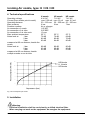
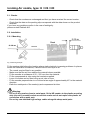
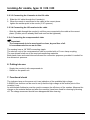
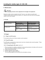
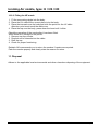
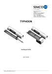
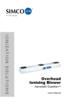
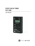
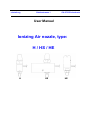
relstatic ag
Gublenstrasse 1
CH-8733 Eschenbach
User Manual
Ionizing Air nozzle, type:
H / HS / HE
H
HS
HE
Ionizing Air nozzle, type: H / HS / HE
CONTENTS
Page
1. Introduction
3
2. Safety
3
3. Use and operation
3
4. Technical specifications
4
5. Installation
4
6. Putting into use
7
7. Functional check
7
8. Maintenance
8
9. Faults
8
10. Repair
8
11. Disposal
9
12. Spare parts
www.relstatic.ch
10
Page 2
Ionizing Air nozzle, type: H / HS / HE
1. Introduction
Read this manual completely before you install and/or put this product into use.
Follow the instructions set out in this manual to ensure proper operation of the product and to
be able to invoke guarantee.
The guarantee terms are stated in the General Conditions for the Sale and Delivery of Products
and/or Performance of Activities by Relstatic AG.
2. Safety
− The Simco ionizing air nozzles are only designed to simultaneously clean and neutralize
electrostatically charged surfaces.
− Do not use the ionizing air nozzles in fire and/or explosion hazardous environments.
− Make sure that the equipment is properly earthed. (Not for separate HE nozzle(s))
Earthing is needed to ensure proper operation and to avoid electrical shocks upon contact.
− When carrying out work on the equipment: de-energize the equipment.
− Electrical installation and repairs shall be performed by a skilled electrical engineer.
− If changes, adjustments, etc. have been made without prior consent in writing, or if nonoriginal parts have been used for repairs, guarantee can no longer be invoked for the
equipment.
3. Use and operation
The Simco ionizing air nozzles are used to clean and neutralize electrostatically charged
surfaces. The use of compressed air allows awkward places to be neutralized and cleaned as
well.
Connected to a Simco power unit, the ionizing air nozzles produce an air flow which is rich in
positive and negative ions. When this air flow is pointed to an electrostatically charged area,
electrons are exchanged until the area is neutralized. This makes that the material is neutralized
during the blow-off process and prevents the blown-off particles from being re-attracted. The
current of type HE and HS nozzles is limited, so that the emitter points of the HS nozzles are
safe to touch (type HE to a limited extent only).
www.relstatic.ch
Page 3
Ionizing Air nozzle, type: H / HS / HE
4. Technical specifications
H nozzle
4 kV AC
max. 2.50 mA
50 – 250 mm
6 bar
Air or nitrogen
1/8” NPT
3/8” BSP
10 mm
55° C
78 dB
86 dB
89 dB
Air consumption (Nm3/h)
Operating voltage
Current (from emitter point to earth)
Operating distance
Max. pressure
Pressure medium
Air connection of nozzle
Air connection of air tube
Air connection of air tube cock
Max. ambient temperature
Noise level at:
1 bar
2 bar
3 bar
measured at 60 cm distance, beside the
nozzle
88 dB
Noise level at:
1 bar
2 bar
93 dB
96 dB
3 bar
measured at 60 cm distance, beside
multiple nozzles on an air tube
12
HS nozzle
7 kV AC
max. 20 μA
50 – 250 mm
6 bar
HE nozzle
7 kV AC
max. 0.5 mA
50 – 250 mm
7 bar
55° C
76 dB
82 dB
84 dB
55° C
68 dB
76 dB
80 dB
86 dB
90 dB
93 dB
80 dB
86 dB
91 dB
HS-Nozzle
H -Nozzle
HE-Nozzle
10
8
6
4
2
0
0
1
2
3
4
5
6
Airpressure (bar)
Fig.1 Air Consumption per nozzle.
5. Installation
Warning:
− Electrical installation shall be carried out by a skilled electrical fitter.
− When carrying out work on the equipment: de-energise the equipment.
www.relstatic.ch
Page 4
Ionizing Air nozzle, type: H / HS / HE
5.1. Checks
− Check that the nozzles are undamaged and that you have received the correct version.
− Check that the data on the packing slip corresponds with the data shown on the product
received.
If you have any problems and/or in the case of ambiguity:
please contact Relstatic AG.
5.2. Installation
5.2.1. Mounting
Material
Fig. 2 Mounting example
Fit the nozzles right before the location where static electricity is causing problems. In places
where the material is neutralized, it should have a free layer of air.
− The nozzle may be fitted in any position.
− Make sure that the air flow reaches the material where possible.
− Fit the nozzles at a distance of 50 – 250 mm from the material.
− Fit the compressed air tube using the brackets supplied.
− Loose H nozzles can be fitted using an air tube or hose.
− Fit the nozzles perpendicular to or inclined at an angle of approximately 45° to the material
direction.
− Earth the metal parts of the nozzle(s) and compressed air tube.
Warning:
− Do not fit the nozzles close to metal parts, fit the HE nozzles to the plastic mounting
strip (do not fit a metal bracket around the nozzle and do not replace the plastic air
connection with a metal one).
− Do not lay non-shielded high-voltage cables alongside sharp metal parts.
www.relstatic.ch
Page 5
Ionizing Air nozzle, type: H / HS / HE
5.2.2. Connection to the power unit
− Using the assembly clamps supplied, fix the HV cable alongside the machine frame.
− Connect the HV cable to the power unit,
see the power unit manual.
Check that the output voltage of the power unit is correct.
5.2.3. Loose nozzles connected to HV cable
5.2.3.1 Overview
If 2 or more nozzles are supplied for being connected to one HV cable, the “DE” (dead end)
nozzle is already connected to the cable. The other nozzles are supplied as loose items and can
be connected to the cable by client.
Fit the nozzles in the position you like, with the “DE” sprayer located farthest from the power unit
being removed. Then lay the HV cable via the nozzles to the power unit.
5.2.3.2. Connecting the HE nozzles to the HV cable
Warning:
− Do not lay non-shielded high-voltage cables alongside sharp metal parts.
− Do not kink the high voltage cables and do not lay them in sharp curves.
1.
2.
3.
4.
5.
Remove the top.
Slide the internals to the top of the body.
Lay the cable in the curvature of the body.
Press the internals onto the cable so that the point sticks into the cable core.
Place the top over the body and internals so that it clicks onto the body.
Fig. 3 Configuration of HE nozzle
www.relstatic.ch
Page 6
Ionizing Air nozzle, type: H / HS / HE
5.2.3.3 Connecting the H nozzles to the HV cable
1. Slide the HV cable through the H nozzle(s).
2. When the nozzle is connected to the cable at the correct place:
tighten the emitter point in the nozzle (3/16” spanner).
5.2.3.4 Connecting the HS nozzles to the cable
− Slide the cable through the nozzle(s) until they are connected to the cable at the correct
place. (Emitter point is already fitted and need not be tightened.)
5.2.4. Connecting the compressed air tube
Important:
− The compressed air to be used must be clean, dry and free of oil.
It is recommended to use an air filter.
The nozzles have a 1/8” BSP connecting nipple.
The shut-off cock of the compressed air tube is provided with a 10 mm clamp coupling.
The user himself shall see to the required connecting materials.
Both plastic hose and metal tube are allowed for connection purposes, provided it is suited for
the relevant air pressure.
6. Putting into use
− Supply the nozzle(s) with compressed air.
− Switch on the power unit.
7. Functional check
The indicator lamp on the power unit is an indication of the available high voltage.
A SIMCO bar checker can be used to verify that the high voltage at the emitter point of the
nozzle(s) is on.
An electrostatic fieldmeter must be used to measure the efficiency of the nozzles. Measure the
charge on the material before and after the nozzle(s) have been used for cleaning by blowing
off. The charge measured should have disappeared after cleaning.
www.relstatic.ch
Page 7
Ionizing Air nozzle, type: H / HS / HE
8. Maintenance
Warning:
− When carrying out work on the equipment: de-energise the equipment.
Clean the emitter points at regular intervals. To do so, use a hard non-metal brush.
If heavily fouled: remove the points (using a 3/16” spanner) and clean them with isopropyl
alcohol (not for HE nozzles).
9. Faults
Problem
No/poor ionization
No high voltage on the
emitter points
Cause
No high voltage
Emitter point fouled
Emitter point damaged
High voltage power unit
defective
Short circuit in the HV
cable or nozzle
Remedy
Restore high voltage
Clean emitter point
Replace emitter point
Repair the high voltage
power unit
Eliminate short circuit
and/or return nozzle for
repair
Table 1: faults
10. Repair
10.1. Type H and HS nozzles
The top and emitter point of these nozzles can be replaced.
10.2. Type HE nozzles
The HE nozzle comprises four components: top, body, internals and connecting nipple. These
components can be replaced.
10.2.1. Dismantling the HE nozzle (see fig. 3)
1. Place the blade of a suitable screwdriver into the opening between the body and the top and
force up the top by turning the screwdriver a little.
2. Take the top from the body.
3. Take the internals from the body.
4. The HV cable can now be removed.
The connecting nipple can be removed from the body by turning.
www.relstatic.ch
Page 8
Ionizing Air nozzle, type: H / HS / HE
10.2.2. Fitting the HE nozzle
1. Fit the connecting nipple into the body.
2. Place the HV cable at the correct place in/on the body.
3. Place the internals over the body and stick the point into the HV cable.
Attention: point must touch the cable core.
4. Place the top over the body, press down the hood until it clicks.
Check the operation of the nozzle after it has been fitted.
When there is no voltage on the points:
1. Remove top from nozzle.
2. Re-stick end of internals into the cable.
3. Refit the top.
4. Check for proper functioning.
Relstatic AG recommends you to return the nozzles if repairs are required.
Pack the nozzles properly and clearly state the reason for return.
11. Disposal
Adhere to the applicable local environmental and other rules when disposing of the equipment.
www.relstatic.ch
Page 9
Ionizing Air nozzle, type: H / HS / HE
12. Spare parts
H nozzle
Item No.
Description
64.99.34.4040
34.99.34.3150
34.99.34.3160
64.99.40.0011
64.99.34.4053
20.00.46.0001
Chrome top
Body (through-going)
End nozzle body
Emitter point
Connecting nipple
3/16” spanner
HS nozzle
Item No.
Description
64.99.34.4040
34.99.00.0002
34.99.00.0011
Chrome top
Body (through-going)
Body (through-going), for
screened cable
End nozzle body
Emitter point
Connecting nipple
3/16” spanner
34.99.00.0001
64.99.40.0008
64.99.34.4053
20.00.46.0001
HE nozzle
Item No.
Description
34.07.50.2000
34.07.50.2020
34.07.50.2100
64.07.90.4000
34.07.90.0000
64.99.34.4054
Top (through-going)
Top (end nozzle)
Internals
Body (through-going nozzle)
Mounting strip
Air connecting nipple (plastic)
www.relstatic.ch
Page 10