1
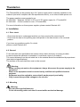
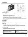
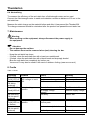
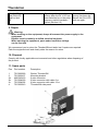
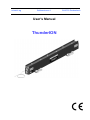
relstatic ag
Gublenstrasse 1
User's Manual
ThunderION
CH-8733 Eschenbach
Thunderion
CONTENTS
Page
1. Introduction
3
2. Safety
3
3. Technical specifications
4
4. Installation
5
5. Commissioning
7
6. Functional check
8
7. Maintenance
9
8. Faults
9
9. Repair
10
10. Disposal
10
11. Spare parts
10
Appendix 1: Wiring diagrams
11
www.relstatic.ch
Page 2
Thunderion
Preface
Read the whole manual before you install and commission the product.
Follow the instructions set out in this manual to ensure proper operation of the product and to
retain your entitlement under the guarantee.
Where the word 'bar' is used in this manual, it refers in all cases to the ThunderION.
The terms of guarantee are set out in the Relstatic AG General Terms and
Conditions of Sale.
1. Introduction
The ThunderION is designed to neutralise the static charge of sheets, webs and other flat
materials. The bars may be used in combination with a 24 V DC power supply.
The 24 V is converted in the bar into a positive and negative high voltage.
The high voltage generates an electrical field at the emitters of the anti-static bar, which causes
the air molecules around the emitters to be converted to positive and negative ions.
When an electrostatically-charged material comes close to the bar, electrons are exchanged
until the material is neutral.
By default, the bar operates with a pulse frequency of 5 Hz. This pulse frequency is used to produce positive and negative ions alternately. The pulse frequency is adjustable and depends on
the application.
The ThunderION incorporates functions for remote switching on and off as well as for remote
functional checking (not wireless).
2. Safety
− Work on the equipment must be carried out by a skilled and qualified electrical engineer.
− When working on the equipment, always disconnect the power supply to the equipment.
− Make sure that the equipment is properly earthed (see installation).
Earthing is needed to ensure safe and proper operation.
The high-voltage emitters (30 kV) are current limited, making them "touchable". If overloading or
a short circuit occurs, the equipment will switch off for 2 seconds and then attempt to switch the
voltage on again.
If a repeated or continuous overload or short circuit occurs, the high voltage will remain
switched off. The high voltage can then be switched on again by switching off the supply voltage
for a few seconds.
− Despite the protection, touching the emitters can cause a shock reaction
(maintain a distance of at least 30 cm from the bar).
− The emitters have sharp edges.
− High voltages are hazardous for people who have a pacemaker.
− The concentration of ozone generated varies per application and must be checked.
− If changes or modifications, etc. have been made without prior consent in writing, or if original
parts have not been used for repairs, CE/UL approval for the equipment will be withdrawn
and the equipment will no longer be under guarantee.
www.relstatic.ch
Page 3
Thunderion
3. Technical specifications
Power supply
Supply voltage
21 – 27 V DC stabilised *
Max. current consumption 0.7 A DC
Connection
Hirschmann GO6WF connector
Output
Output voltage
Short-circuit protection
Max. current from emitter
to earth
Emitter material
<0.7 mA
Special alloy
Environment
Operating environment
Ambient temperature
Cooling
Operating distance
Industrial
0 – 55°C
convection
300 – 1000 mm
Local functions
Frequency setting
Indication of pulse
frequency setting
[On] signalling
[Fault] signalling
Remote functions
Remote On/Off
Bar operating OK
Mechanical
Effective bar length
Dimensions (WxHxL)
Weight
Housing
Mounting material
Max. 30 kV positive and negative
Output electronically protected at max. output current
1…10 Hz in 1 Hz increments; can be adjusted using the
rotary switch behind the PG-7 stopper.
Flashing red and yellow LEDs during start-up of the bar
and after adjustment of the pulse frequency.
Yellow LED
- Red LED lights up in the case of an overload or
short circuit.
- Red LED flashes when a repeated or
continuous overload or short circuit has occurred.
Switching high voltage on and off
Control voltage specifications:
10 V DC, 10 mA min.
30 V DC, 25 mA max.
Indicates that the bar is operating correctly
(when high voltage is switched on).
Max. load: 30 V DC, 50 mA.
250 mm to 4000 mm
47 mm x 93 mm x total length (Eff. Length + 205 mm)
0.8 kg + 1.5 kg/m
Glass-fibre strengthened plastic
Sliding nuts, screws, brackets and connector
* The power supply must be a Limited Power Supply or NEC Class 2 power supply.
The output of the power supply must be properly grounded! (See para. 4.4.1.)
An LPS certified power supply has a limited output power, as a result of which it
always generates a safe output voltage.
www.relstatic.ch
Page 4
Thunderion
The ThunderION can be powered by a 24 V power supply which is already available on the
machine (and which complies with the requirements above), or an other suitable power unit.
The power supplies recommended by us:
4510001000 Separate 100-240 V AC to 24 V DC power supply for 1 ThunderION
4510001400 Control module for max. 4 ThunderIONs
For more information on these power supplies, please contact Relstatic AG.
4. Installation
4.1. Prior check
- Check that the bar is undamaged and that you have received the correct model.
- Check that the data on the packing slip corresponds to the data shown on the received
product.
If you have any problems and/or if in doubt:
please contact Relstatic AG.
4.2. General
Fit the anti-static bar right before the location where static electricity is causing troubles.
In places where the material is neutralised, it must have a layer of air under it.
The correct distance from the anti-static bar to the material should be established by experiment
(see technical specifications).
The emitters of the anti-static bar must not be covered.
-
Warning:
When carrying out work on the equipment, always disconnect the power supply to the
equipment.
Work on the equipment must be carried out by a skilled and qualified electrical
engineer.
Equipment must be earthed to ensure that it works properly and safely.
Only connect the specified voltages to the circuits.
4.3. Mounting
-
Warning:
Use only the supplied fasteners.
Fit the connecting cable such that it cannot suffer mechanical damage.
www.relstatic.ch
Page 5
Thunderion
Figure 1
− Fit the anti-static bar with the emitters towards the material to be discharged.
Use the supplied mounting materials, see fig. 1.
− Mount the bar such that the emitters are at a distance of at least 50 mm from electrically conductive machine parts. This prevents spark-over.
If this distance cannot be achieved, an optional side panel can be placed,
item number: 7510900010.
Only use the side panel if absolutely necessary, as the bar operates less effectively when the
side panel is fitted.
4.4 Connection
4.4.1. Earthing
For personal protection and to ensure proper functioning, the following earth connections must
both be made:
− the fitted (yellow/green) earth wire to an earthed part of the machine.
− the 0 V of the power cable on the supply side to earth.
In the power units supplied by us, the internal 0 V is connected to the safety earth. Make
sure that the power cable of the power units is earthed correctly.
4.4.2. Supply voltage
− Ensure that the supply mains voltage is correct.
− Connect the connector to the bar according to one of the diagrams (see Appendix 1).
Without remote On/Off
Position two jumpers on the connector and
connect the supply voltage here:
Pins 1 and 2 (+24 V)
Pins 5 and 6 (0 V)
www.relstatic.ch
With remote On/Off
Connect the supply voltage to pin 1 (24 V)
and pin 6 (0 V)
Connect the control voltage to:
Pin 2 (+24 V DC) and pin 5 (0 V)
Page 6
Thunderion
4.4.3. External Bar operating OK signalling
It is possible to check the bar's functioning remotely with a PLC, for instance. For this purpose,
an optocoupler output is available on the connector (max. load 30 V DC, 50 mA).
Connect the external signalling to pins 3 and 4 of the connector according to the diagram
(Bar operating OK: see Appendix 1).
5. Commissioning
-
Warning:
High voltage can be dangerous to people with a pacemaker.
Check that the bar is earthed correctly (see para. 4.4.1).
Touching live emitters causes an unpleasant electric shock.
Without remote On/Off
With remote On/Off
Switch on the 24 V DC supply voltage
(the bar is not yet activated).
Switching on
Switching on (first time after switching on
24 V DC supply voltage)
Connect the control voltage to the remote
On/Off contacts (pins 2 and 5).
The yellow [On] LED lights up briefly, the red
[Fault]-LED will then flash 10 times quickly,
the yellow [On]-LED then flashes a number of
times slowly (this indicates the position of the
pulse frequency switch); the [Fault]-LED
flashes 10 times quickly and then the [On]LED lights up.
Switching on
Connect the control voltage to the remote
On/Off contacts (pins 2 and 5)
The yellow [On] LED lights up.
Switch on the 24 V DC supply voltage.
The yellow [On] LED lights up briefly, the red
[Fault] LED will then flash 10 times quickly,
the yellow [On] LED then flashes a number of
times slowly (this indicates the position of the
pulse frequency switch); the [Fault] LED
flashes 10 times quickly and then the [On]
LED lights up.
Switching off
Switch the 24 V DC supply voltage off.
The yellow [On] LED goes out.
Switching off
Switch the control voltage off.
The yellow [On]-LED goes out, the supply
voltage remains on the bar, but the bar is not
active.
To de-energise the bar, switch off the
24 V DC supply voltage.
Behind the screw cap is a 10-position switch, which can be used to set the pulse frequency.
At the factory, this is set to a default value which will provide good results for most applications.
www.relstatic.ch
Page 7
Thunderion
6. Functional check
6.1. Internal
6.1.1. [On]-LED
The [On] LED lights up if the remote On/Off input is activated.
6.1.2. [Fault]-LED
The [Fault]-LED lights up (the [On]-LED also lights up):
- if the bar is overloaded,
- in case of spark-over.
The [Fault]-LED flashes quickly (the [On]-LED also lights up):
- if the bar is overloaded repeatedly or continuously,
- in the event of repeated spark-over.
In the event of overloading or a spark-over, the bar will be switched off briefly.
Overloading can be caused by fouling or because the bar is mounted in the wrong place.
(See para. 4.3.) The bar remains switched off if it is repeatedly or continuously overloaded or if
repeated spark-over has occurred. The bar can be switched on again by switching off the supply
voltage for a few seconds.
6.2. Indication of pulse frequency switch position with [Fault]-LED and [ON]-LED
After the 24 V DC supply voltage is switched on, the [Fault] LED and [On] LED are used to
indicate the position of the pulse frequency switch. This works as follows:
- the red [Fault]-LED flashes 10 times quickly.
- the yellow [On]-LED flashes slowly. The number of flashes corresponds to the position
of the switch (0 to 9 flashes).
- the red [Fault]-LED flashes 10 times quickly.
After the pulse frequency has been displayed, the [On]-LED lights up again (Remote = ON).
If the switch for the pulse frequency is turned during operation, the pulse frequency will also be
indicated as described above.
During indication of the pulse frequency using the [Fault]-LED and [On]-LED, a high voltage is
present on the emitters. If a fault occurs during indication of the pulse frequency, the [Fault]-LED
lights up and the pulse frequency indication is turned off.
6.3. External: Bar operating OK function
The external Bar operating OK output is active if the following three conditions are met:
− the supply voltage is present on pins 1 and 6,
− the bar is activated via pins 2 and 5 (remote On/Off contact),
− there is no fault (see para. 6.1.2.).
www.relstatic.ch
Page 8
Thunderion
6.4. Neutralising
To measure the efficiency of the anti-static bar, a field-strength meter can be used.
Connect the field-strength meter to earth and maintain a minimum distance of 30 cm to the
anti-static bar.
Measure the static charge on the material before and after it has passed the ThunderION.
The charge measured should be minimized after the product has passed the anti-static bar.
7. Maintenance
Warning:
− When working on the equipment, always disconnect the power supply to
the equipment.
Attention:
− Do not damage the emitters.
− The emitters must not be removed when (wet) cleaning the bar.
− Keep the anti-static bar clean.
− If fouled: clean the anti-static bar with a hard non-metal brush.
− If fouled: clean the anti-static bar with a block brush and isopropyl alcohol.
Blow the anti-static bar completely dry before use.
Veconova 10 may also be used in the event of stubborn fouling (www.eco-nova.nl)
8. Faults
Table 1: Faults
Signalling
[On]-LED on
[Fault]-LED off
Bar operating
OK active
(external)
[On]-LED off
[Fault]-LED off
Problem
No/poor ionisation
High voltage on emitters.
Cause
Bar is fouled.
Emitters are damaged.
Emitters are covered.
Remedy
Clean bar.
Replace emitters.
Remove the cover.
No high voltage on
emitters.
Remote function set to Off.
No supply voltage
present.
Bar faulty.
Set Remote to On.
Restore supply voltage.
Bar placed too close to conductive parts.
Move bar.
Bar is extremely fouled.
Clean bar.
Bar faulty.
Return bar.
Bar operating
OK not active
(external)
No high voltage on
[On]-LED on
[Fault]-LED on emitters.
or flashes
Bar operating
OK not active
(external)
www.relstatic.ch
Return bar.
Page 9
Thunderion
[Fault]-LED
and [ON]-LED
flash on and
off
None
Signalling of the pulse frequency after the 24 V DC has
been switched on or the pulse
frequency switch has been
turned (Section 6.2)
After the pulse frequency has been displayed, the [On] LED
turns on again.
9. Repair
-
Warning:
When working on the equipment, always disconnect the power supply to the
equipment.
Repairs must be made by a skilled electrical engineer.
When opening the equipment, parts under hazardous voltage
can be touched.
We recommend you to return the ThunderION anti-static bar if repairs are required.
Pack the equipment well and clearly state the reason for return.
10. Disposal
Comply with locally applicable environmental and other regulations when disposing of
the product.
11. Spare parts
Pos. Part number
Description
1
2
3a
3b
3c
4
Emitter ThunderION
Mounting bracket
6-pole connector
6-pole connector with cable 6 m
6-pole connector with cable 12 m
ThunderION side panel
7510990000
7510900157
6603060120
7510004600
7510004602
7510900010
www.relstatic.ch
Page 10
Thunderion
Appendix 1: Wiring diagrams
www.relstatic.ch
Page 11