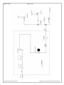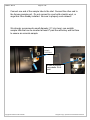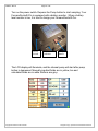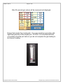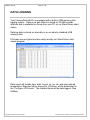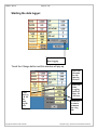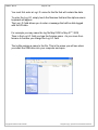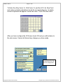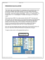
1
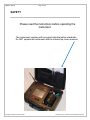
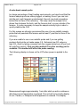
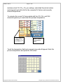
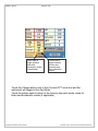
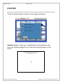
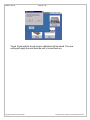
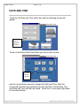
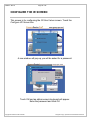
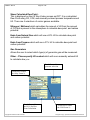
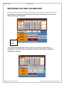
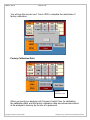
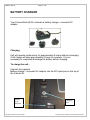
FurnaceDoctor®-Pro USER MANUAL Version Number 18 FDPRO –Rev.18 Page 2 of 55 Manual #: 006 Rev No: 018 COPYRIGHT(C) No part of this publication may be reproduced, transmitted, transcribed, stored in a retrieval system, or translated into any language or computer language, in any form or by any means, electronic, mechanical, magnetic, optical, chemical, manual, or otherwise, without prior written permission of United Process Controls Inc.. DISCLAIMER: The FurnaceDoctor®-Pro is to be used by the industrial operator under his/her direction. United Process Controls Inc.is not responsible or liable for any product, process, damage or injury incurred while using the FurnaceDoctor®-Pro. United Process Controls Inc. makes no representations or warranties with respect to the contents hereof and specifically disclaims any implied warranties or merchantability or fitness for any particular purpose. For assistance please contact: United Process Controls Inc. TEL: +1 513 772 1000 • FAX: +1 513 326 7090 Toll-Free North America +1-800-547-1055 [email protected] www.group-upc.com ****CAUTION**** DO NOT CLOSE CHARGER IN LID SCREEN CAN BE DAMAGED NOT COVERED BY WARRANTY Copyright © United Process Controls. All rights to copy, reproduce and transmit are reserved. FDPRO –Rev.18 Page 3 of 55 TABLE OF CONTENTS SAFETY ........................................................................................................................................................... 4 EQUIPMENT RATINGS .................................................................................................................................. 5 THEORY .......................................................................................................................................................... 6 OPERATIONS ................................................................................................................................................ 13 DATA LOGGING ............................................................................................................................................ 23 THE MENU SYSTEM ..................................................................................................................................... 31 UTILITIES ....................................................................................................................................................... 34 DATE AND TIME ............................................................................................................................................ 37 CONFIGURE THE IR SCREEN ..................................................................................................................... 37 PROCESS CALCULATOR ............................................................................................................................ 41 CALIBRATION ............................................................................................................................................... 44 RESTORING FACTORY CALIBRATION ..................................................................................................... 48 BATTERY CHARGER .................................................................................................................................... 50 ETHERNET OPTION ...................................................................................................................................... 52 WI-FI OPTION ................................................................................................................................................. 54 Copyright © United Process Controls. All rights to copy, reproduce and transmit are reserved. FDPRO –Rev.18 Page 4 of 55 SAFETY Please read the instructions before operating the instrument. This instrument complies with accepted industrial safety standards. Do NOT operate this instrument with the internal top cover removed. Copyright © United Process Controls. All rights to copy, reproduce and transmit are reserved. FDPRO –Rev.18 Page 5 of 55 EQUIPMENT RATINGS Supply Voltage Supply Frequency Power Consumption 110-240 VAC 50/60 Hz 3.2/1.8 Amps Certifications/Compliance Range CO 0-30 % CO2 0-2% CH4 0-10% Operating Temperature Relative Humidity Resolution Accuracy 0.02 % 20 ppm 0.02 % 2% of range 1% of range 2% of range 40°F - 120°F 5% - 90% non-condensing Atmospheres: Suitable for: Carburizing Carbonitriding Carbon Correction Neutral Hardening Austempering Martempering Precipitation Hardening Annealing Normalizing Stress – Relieving *call FCC if your process is not listed* **NH3 (ammonia) is strictly prohibited in the sample** Copyright © United Process Controls. All rights to copy, reproduce and transmit are reserved. FDPRO –Rev.18 Page 6 of 55 THEORY Why Infrared? By purchasing your new FurnaceDoctor®-Pro, you have obviously made the decision that your current process measurement methods require some enhancement. This may be due to customer requirements for back-up process verification to your existing oxygen probe based system or simply a matter of answering the question “is that probe really working?” You might be looking for more complete information of what is happening with respect to your furnace atmosphere. Whatever your reasons, the use of I/R analysis, and the FurnaceDoctor®Pro will satisfy these requirements. Since most FurnaceDoctor®-Pro owners are either performing gas carburizing, or neutral hardening in an endothermic atmosphere, the following discussion will help to understand the meaning of the measured values: Endothermic atmospheres in use for these applications have this basic composition: CO 20% H2 40% CO2 Trace CH4 Trace O2 Trace H2O Trace N2 .Balance (carbon monoxide) (Hydrogen) (carbon dioxide) (methane, usually from natural gas) (oxygen) (water vapor) (nitrogen) These ratios are typical whether you are producing gas by means of an endothermic generator, or using prepared gasses such as nitrogen and methanol. Ratios are slightly different if propane is used rather than methane for the production of carrier gas. Obviously any increase in volume in one of the gasses means a decrease in one or more of the other gasses. We often get asked the question “Why is my generator producing 20% CO, but I am only measuring 17% at my furnace?” “It is even lower when I add ammonia!” One part of the answer to Copyright © United Process Controls. All rights to copy, reproduce and transmit are reserved. FDPRO –Rev.18 Page 7 of 55 this question is simple volumetric displacement. There is only room in the furnace for 100% of the atmosphere! How can the FurnaceDoctor®-Pro help me with my generator? The basic chemical reaction taking place in an endothermic generator is as follows: 2CH4 + O2 2 CO + 4 H2 Ignoring the nitrogen Remember you are mixing gas and air together and heating it up to produce the above described gas composition. The reaction takes place in two stages: First some of the methane burns with air and makes heat. The by-products of this combustion are H2O (water vapor), and CO2. In the second stage, the remaining methane reacts with the CO2, and H2O. It becomes obvious that we want this reaction to be as complete as possible! This is the reason for the nickel catalyst in the generator. Assuming that the main air gas ratio is set somewhere between 2.7 and 2.85 parts air to 1 part gas, there are two considerations: 1. The catalyst must be clean, and free from soot. If soot is present, the efficiency of the above reactions goes down. 2. You must have adequate temperature to keep the rate of the reactions high enough. So how can the FurnaceDoctor®-Pro help? First by measuring the generator’s methane content you can determine whether or not the catalyst is operating efficiently. .8% CH4 is about the upper limit. Above this level it is possible that the catalyst is laden with soot, or the catalyst is simply spent. Another indication of this condition would be a high CO2, or dew point. The FurnaceDoctor®-Pro provides a convenient way to obtain dew point, CO, CO2, and CH4. Copyright © United Process Controls. All rights to copy, reproduce and transmit are reserved. FDPRO –Rev.18 Page 8 of 55 Check to see that the basic gas composition is as expected. CO should be around 20%. Check the CH4 level and be sure that it is less than .8%, observe the CO2, and the dew point readings. Note the relationship between dew point, and CO2. 1.60 1.40 1.20 1.00 0.80 0.60 0.40 0.20 0.00 0 20 40 60 Dewpoint 80 %Carbon Dioxide Carbon Dioxide VS Dewpoint 100 Make adjustments to either your oxygen probe control system, or the generator carburetor to obtain the desired dew point. How will the FurnaceDoctor®-Pro help me with my Furnace atmosphere? If you are using oxygen probes the FurnaceDoctor®-Pro can supply independent, traceable verification of your probes accuracy. It will also give you a much more complete picture of what is happening in your furnace atmosphere. The primary reactions involved in carbon transfer are well understood as: 2CO C +CO2 H2 + CO C + H2O Copyright © United Process Controls. All rights to copy, reproduce and transmit are reserved. FDPRO –Rev.18 Page 9 of 55 These reactions are assumed to be close to equilibrium. The theory behind this is that a reaction sometimes called the water-gas reaction, is busy keeping the H2 and O2 in balance: CO + H2O CO2 +H2 The measurement of %Carbon in your atmosphere with an oxygen probe is based on the assumption that the above is true: CO C + ½ O2 Note that it is assumed that the primary mechanism of carbon transfer is CO dependant. What is really happening is that the ratio of CO to CO2 is much more accurate means of determining equilibrium carbon. One problem is that we use CH4 as enriching gas. What happens to the CH4 once it enters the furnace? It decomposes - mostly near the hot catalytic surfaces in your furnace. It may be replenishing depleted CO, based on equilibrium “rules” it may be making soot crumbs on your hearth, or it may be reacting directly with the surface of the material: CH4C + 2H2 How much of the above reaction is happening is dependent on how much methane is present in your furnace. The reaction also happens faster at higher temperatures, but is still slow compared to the equilibrium reactions. For example at 1600 with an equilibrium carbon potential of .4%, and methane content of .5 the theoretical carbon potential is actually .44%. In reality the effect is usually about 6/10 of what the theoretical calculations deliver making the carbon potential closer to .42%. By contrast if we were to up the methane content to 5%, the actual carbon potential might be closer to .6%, a significant difference! Whether the work really ends up seeing this is dependent on a number of issues - temperature – governing the rate of reaction, the surface area of the work and the level of saturation at the surface, atmosphere circulation, etc. Copyright © United Process Controls. All rights to copy, reproduce and transmit are reserved. FDPRO –Rev.18 Page 10 of 55 Using the FurnaceDoctor®-Pro to analyze furnace atmosphere Probe condition: Carbon is computed using actual gas values, so it is more accurate than the assumptions made by the probe. Compare the %C calculated by the FurnaceDoctor®-Pro to %C displayed on the Carbon Control instrument. Your carbon controller is set up with some assumptions about the content of the furnace atmosphere. Most controllers assume a CO to be 20% “out of the box” you may use the FurnaceDoctor®-Pro to correct this situation by adjusting this “factor” to the correct %CO. Observe the probe millivolts as computed by the FurnaceDoctor®-Pro, and displayed by the carbon controller. These should be within 1-2 % of each other. If not, and you have entered the process temperature into the FurnaceDoctor®-Pro correctly, you probably have a problem with the probe or the controller. First check the millivolt reading at the back of the probe with a meter to eliminate any possible instrument problems. Next be sure that the probe is free of soot by burning the probe off. If the numbers still do not agree, perform an impedance test on the probe to help determine the electrode condition. You will also want to check to see how fast the probe recovers after this test. Recovery time should be in seconds, not minutes. Finally disconnect the probes reference air tube, and see if the millivolts reading on the controller changes, if it does you have a leak in the probe substrate. If you change the probe or if you are sure that the probe is ok, check to be sure you are obtaining a good sample at the FurnaceDoctor®-Pro. Many times sample ports are the cause of the problem. A good non-metallic sample probe helps solve this. One trick is to use the probe burnoff port to obtain a sample. This has a few problems associated with it in furnaces running high methane contents. The methane will crack near the alloy surface of the probe creating a local reaction not representative of the overall furnace atmosphere. Copyright © United Process Controls. All rights to copy, reproduce and transmit are reserved. FDPRO –Rev.18 Page 11 of 55 Interpreting the gas value readings: CO: For most atmospheres in use this number should be around 18-20%. If it is lower than 18% then observe the following: Check generator for proper operation. If you are using nitrogen methanol, check the ratio of nitrogen to methanol. Also be sure that the atmosphere sparger is in good condition. If you are using nitrogen to “push” the methanol into the furnace be sure that the methanol is not getting nitrogen bubbles in it. If you are using ammonia, the ammonia additions will dilute the %CO in the furnace. Remember there is only room for 100% of the gas in the furnace Check for leaks. This can be confirmed by a high CO2. If you are asking for a high carbon potential, high methane content, may also dilute atmosphere mix. Check for leaks. Air leaks typically cause the control system to add more natural gas to the furnace. High surface area loads will be able to draw more carbon out of the atmosphere. Typically the methane content will go up because of this. CO2: This number can be anywhere between .05% to 1% and is dependent on temperature, and gas composition. It tracks inversely to carbon potential. At 1600F a .4%C will be about 0.62% CO2 (assuming 20% CO). To achieve a .4% carbon at 1750 CO2 will be around .25 If the carbon potential is lower than expected the CO2 should be higher than expected. Check for air leaks. Check for burner tube leaks. Check for furnace fan water jacket leaks. Check generator or nitrogen methanol system. If the probe system is in agreement with the FurnaceDoctor®-Pro, be sure there is adequate carrier gas flow, and adequate enriching gas flow. Is carbon controller turning on the natural gas when it should? Copyright © United Process Controls. All rights to copy, reproduce and transmit are reserved. FDPRO –Rev.18 Page 12 of 55 CH4: Most batch furnaces will operate with a CH4 content ranging from .1% to 4-5%. At the start of the cycle this number is higher than when the atmosphere and the work approach equilibrium with each other. Continuous furnaces performing carburizing will usually operate at higher methane levels. In fact in some belt furnace applications this is necessary for the process to work! High free methane content is usually a product of the control system calling for too much natural gas due to an air leak, unusually high surface are in the load. Check for air leaks. Check for burner tube leaks. Check for furnace fan water jacket leaks. Check generator or nitrogen methanol system Be sure that the probe control system is working properly Copyright © United Process Controls. All rights to copy, reproduce and transmit are reserved. FDPRO –Rev.18 Page 13 of 55 OPERATIONS Precautions before operations: 1) Dew point of sampling gas must be lower than the ambient temperature to avoid occurrence of drain in the gas analyzer. If vapor is contained in the sampling gas, dew point should be lowered to 0°C by using a dehumidifier 2) Temperature of sampling gas should be within 0 to 50°C. Provide a means that prevents entry of hot gas directly into the instrument 3) Absolute pressure of sampling gas should be 926 – 1024 mb. Avoid flow or pressure fluctuation during measurement. Observe the flow reading by a flowmeter provided as shown 4) Avoid installing this instrument near an electrical unit (high frequency furnace or electric welder) that generates much electrical noise 5) Allow 20 minutes warm-up for stabilized readings. SAMPLE GAS The condition of the sample must conform to the following requirements to ensure that the performance of the product meets the stated technical specification. Contamination in the sample cell, particularly on the windows, will cause an error in the output reading Avoid degradation of the sample gas between sample point and the sensor by the introduction of unnecessary volumes or restrictions. Eliminate transients which can cause pressure variations. Maintain constant flow conditions. Avoid the use of rubber compounds for the sample tubing (adsorption effects). Copyright © United Process Controls. All rights to copy, reproduce and transmit are reserved. FDPRO –Rev.18 Page 14 of 55 Particles: The gas to be measured must be well filtered. 100 % of 3 m particles must be retained. Humidity: Prior to entry in the FDPRO, the moisture in the gas must be adequately reduced. This means that the dew point of the gas must be brought below the operating temperature of the FDPRO by some means. No moisture can then condense in the ACCUBENCH. Liquids The sample gas must be free of any liquid Entrained oil The sample gas must be free of any contamination. Copyright © United Process Controls. All rights to copy, reproduce and transmit are reserved. FDPRO –Rev.18 Copyright © United Process Controls. Page 15 of 55 All rights to copy, reproduce and transmit are reserved. FDPRO –Rev.18 Page 16 of 55 Connect one end of the sample tube to the inlet. Connect the other end to the furnace sample port. Do not connect to a port with a lamb’s wool, or angel hair filter already installed. Be sure to properly vent exhaust! We strongly recommend a small diameter (½” id or less), non-metallic sample tube that can be inserted at least 2” past the refractory wall hot face to ensure an accurate sample. Connect Sample Tube Here Be sure to properly vent exhaust. CO is toxic! Copyright © United Process Controls. All rights to copy, reproduce and transmit are reserved. FDPRO –Rev.18 Page 17 of 55 Rotate Handel CCW and remove cover. Lift Filter to upright position Be sure that the filter is clean, and free from moisture! Soot build-up or discoloration in the sample element requires the element to be replaced. * Caution * - re-insert the filter element with the same orientation or risk damaging the FDPRO by introducing contaminants into the gas stream Copyright © United Process Controls. All rights to copy, reproduce and transmit are reserved. FDPRO –Rev.18 Page 18 of 55 Turn on the power switch. Depress the Pump button to start sampling. Your FurnaceDoctor®-Pro is equipped with a battery monitor. When a battery level monitor is low, it is time to charge your FurnaceDoctor®-Pro. Power Switch Battery Level Indicator Pump Button The LCD display will illuminate, and the internal pump will start after pump button is depressed. Manually inputted fields are in yellow, live and calculated fields are in white. Buttons are grey. Copyright © United Process Controls. All rights to copy, reproduce and transmit are reserved. FDPRO –Rev.18 Page 19 of 55 After 30 seconds gas values will be measured and displayed. Ensure that sample flow is adequate. If you are sampling a generator with significant pressure at the sample port, 10 SCFH, it is recommended that you partially close the port valve so you do not compress the gas leading to an incorrect reading. Copyright © United Process Controls. All rights to copy, reproduce and transmit are reserved. FDPRO –Rev.18 Page 20 of 55 A note about sample ports: In a large percentage of heat treating environments, we have found that the furnace sample ports are either plugged, or leaking. Even if you can look into the port, and it appears unobstructed, the port may leak somewhere behind the hot face of the refractory. This may cause the sample to be drawn from between the brick, and the furnace shell, or even outside of the furnace. It is also necessary to keep the sample velocity high in order to quickly stabilize the CO2 For this reason we strongly recommend the use of a non-metallic sample probe that will penetrate the furnace wall at least 2” past the hot face of the refractory. If you are unable to use a non-metallic probe and if you are getting numbers that just do not make sense (I.E. Extremely low CO values or high CO2) then try taking a sample from the oxygen probe burn-off port (not the reference airport). Only use this method if no other working port is available. This method will affect the probe reading. The following display is shown on the LCD when power is applied to the unit. Measurement begins approximately 1 min after start up and is continuous after the process temperature is entered. The unit will not correctly display O2 mV, Carbon, or Dewpoint until temperature is entered. The display Copyright © United Process Controls. All rights to copy, reproduce and transmit are reserved. FDPRO –Rev.18 Page 21 of 55 includes actual CO, CO2, CH4 as readings, calculated theoretical carbon and dewpoint and milli-volts for the computed %Carbon and manually entered temperature To compute the correct %C associated with the CO, CO2, and CH4 measured gasses you must enter the process temperature. Touch here to change to oC and back to oF Enter Process Temperature Here Touch the temperature field and a numeric key pad will appear. Enter the process temperature and press the OK button. Copyright © United Process Controls. All rights to copy, reproduce and transmit are reserved. FDPRO –Rev.18 Page 22 of 55 The instrument displays the carbon, dewpoint for the measured CO, CO2, CH4 gasses and entered probe temperature. Additionally, it displays calculated probe millivolts. Calculated prove mV uses an algorithm that assumes CH4 is equal to zero. The instrument will take at least 60 seconds from cold start to display any meaningful information. Ensure that sample flow is adequate! It’s always a good idea to allow at least 3 minutes of operation to obtain a meaningful reading. The FurnaceDoctor®-Pro can be switched between Deg F and Deg C by touching the oF / oC box Selecting the Dew point, Calculation Modes: The instrument will compute dew point using either a temperature based calculation, used when measuring furnace atmospheres where you can identify the process temperature or a simplified table look up method based on CO2 to be used when measuring the dew point of endothermic generators. If you use the furnace calculation when measuring your endothermic generator, and enter a process temperature of 1900F or so, you will get meaningless values for dew point. If you have the generator calculation selected, it is not necessary to enter a process temperature. You must select the correct carrier gas from the Configure I/R Screen. From this screen you can select the correct carrier gas for you process. Copyright © United Process Controls. All rights to copy, reproduce and transmit are reserved. FDPRO –Rev.18 Page 23 of 55 Touch here to toggle between endo and exothermic modes. (If applicable) Touch here to toggle between furnace and generator dew point calculation modes. Touch the Change button next to the Furnace DPT mode text and the instrument will toggle to Gen Dpt Mode. Touch the button again to return to the furnace dew point mode, same for Endo and Exothermic modes (if applicable) Copyright © United Process Controls. All rights to copy, reproduce and transmit are reserved. FDPRO –Rev.18 Page 24 of 55 DATA LOGGING Your FurnaceDoctor®-Pro is equipped with a built in USB memory data logging system. Data on all gas values is stored on 30-999 seconds intervals and is available for review from your PC on our Stand Alone chart viewer. Data log data is stored on internally or on an industry standard USB memory stick. File types are encrypted and are easily read by our Stand Alone chart viewer program. Data saved will include time, date, Log Id, co, co2, ch4, and user entered temperature. Expected o2mv, dew point, %Carbon, will be determined in the “Configure I/R Screen”. The checked items will be data logged. (See Utilities) Copyright © United Process Controls. All rights to copy, reproduce and transmit are reserved. FDPRO –Rev.18 Page 25 of 55 Starting the data logger: Touch here to start Data Logging Touch the Change button and this window will pop up Enter the file name for the data log file here Enter the Log I.D. for the data log file here Copyright © United Process Controls. Enter the Data Logging Interval Here. 30 -999 secs Click here to enter a comment for a log file. All rights to copy, reproduce and transmit are reserved. FDPRO –Rev.18 Page 26 of 55 You must first enter a Log I.D. name for the file that will contain the data. To enter the Log I.D. simply touch the filename field and the alpha numeric keyboard will appear. The Log I.D. field allows you to enter a message that will be data logged with the I/R data. For example you may name the log file May2109 for May 21st, 2009 Then in the Log I.D. field you type the furnace name. As you move from furnace to furnace you change the Log I.D. field. The logfile assigns a name to the file. This is the name you will see when you insert the USB drive into your computer and open. Copyright © United Process Controls. All rights to copy, reproduce and transmit are reserved. FDPRO –Rev.18 Page 27 of 55 Starting and Stopping Data logging: To start data logging insert the USB flash drive in to the top of the FurnaceDoctor®-Pro. Insert USB flash drive here Compatible USB FLASH Memory Sticks: - Dane Electric (DA-ZMP-02G-CA-W1-R) PQI Mr. Flash U172 ( Model # BB55-B1G3-0221) Corsair ( Model # CMFUSBSF2.0-128) Viking Interworks ( Model # USB00256L2) Kingston DataTravler ( Model # DTI/1GBKR) PNY Technologies ( Attache 256 or 512) Lexar JumpDrive Viking ( Model # USB0032L) Sony ( Model # Microvalt) Dell ( Model # Memory Key) Copyright © United Process Controls. All rights to copy, reproduce and transmit are reserved. FDPRO –Rev.18 Page 28 of 55 Touch the Change button next to the LOGGING: OFF text. Touch here to start and stop data logging A window will pop up. Enter the Log I.D., log file name and Data Log Interval by touching the appropriate area. Touch the Start Logging button and touch OK. Copyright © United Process Controls. All rights to copy, reproduce and transmit are reserved. FDPRO –Rev.18 Page 29 of 55 A window pops up stating Please insert an USB memory stick. Insert the USB stick and touch OK to start data logging. After Touching OK the text next to the Change button will state Logging: ON and will display the logfile name in green. Log file Name in Green To stop Data Logging push the Change button. Copyright © United Process Controls. All rights to copy, reproduce and transmit are reserved. FDPRO –Rev.18 Page 30 of 55 Touch the Change button to stop Data Logging You will see this screen. Touch on the StopLogging and then touch OK. A window will pop up stating Data Logging Stopped Copyright © United Process Controls. All rights to copy, reproduce and transmit are reserved. FDPRO –Rev.18 Page 31 of 55 Touch OK and another window will pop up stating ‘It is now safe to remove your USB memory stick’. Press OK to acknowledge. Remove the USB drive and insert into your PC to read the data of the encrypted file on the standalone chart viewer. Copyright © United Process Controls. All rights to copy, reproduce and transmit are reserved. FDPRO –Rev.18 Page 32 of 55 THE MENU SYSTEM Main Menu Button Touching the Main Menu button will take you to the system main menu. Copyright © United Process Controls. All rights to copy, reproduce and transmit are reserved. FDPRO –Rev.18 Page 33 of 55 The following options are available on the main menu: I/R Gas values – This is the display that you see when the instrument is first powered up. Data includes CO, CO2, CH4, and user entered temperature. Expected O2mv, dew point, %Carbon, will be determined in the “Configure I/R Screen” page 45. The checked items will be displayed and logged. Utilities - This allows you to calibrate the touch screen, set the date and time, View internally stored data on a chart and configure the I/R Gas Values screen. Proc Calc – Allows you to enter temperature, oxygen probe millivolts or CO, CO2, CH4, H2, Alloy Factor, and CH4 Factor to compute carbon potential and dew point. You can also enter the dew point and temperature to compute the above. Calibration – This option allows you to calibrate the instrument to certified grade gasses About—tells about software version, customer support and the members of United Process Controls. View chart – Allows the user to view internally stored data on a graphical chart. Copyright © United Process Controls. All rights to copy, reproduce and transmit are reserved. FDPRO –Rev.18 Page 34 of 55 UTILITIES Touch the desired option to select. A new window will pop up. Calibrate Touch – Allows you to calibrate the touch positions on the screen by locating a target for you to touch at various positions on the screen. Copyright © United Process Controls. All rights to copy, reproduce and transmit are reserved. FDPRO –Rev.18 Page 35 of 55 Follow the instructions to calibrate the touch screen. After completion of touch screen calibration the cross will disappear. It may take several tries. You will see this screen. Touch anywhere on the screen to finish the touch screen calibration. You will then be prompted to save Calibration Settings. Touch Save. You will then see this screen Copyright © United Process Controls. All rights to copy, reproduce and transmit are reserved. FDPRO –Rev.18 Page 36 of 55 Touch Close and the touch screen calibration will be saved. The new setting will apply the next time the unit is turned back on. Copyright © United Process Controls. All rights to copy, reproduce and transmit are reserved. FDPRO –Rev.18 Page 37 of 55 DATE AND TIME Touch the Set Date and Time check box and the following screen will appear. Touch Here to Close the Window Touch on the Enter Date/Time button you will see this screen Up and Down Arrows Use the up and down arrows to change the Date and Time. After the correct date and time are entered touch the Set Date / Time button. The new Date and Time will then be saved. Touch the x in the upper right hand to close the window. Copyright © United Process Controls. All rights to copy, reproduce and transmit are reserved. FDPRO –Rev.18 Page 38 of 55 CONFIGURE THE IR SCREEN This screen is for configuring the I/R Gas Values screen. Touch the Configure I/R Screen box. A new window will pop up you will be asked for a password. Touch OK and an alpha numeric keyboard will appear. Enter the password and click OK. Copyright © United Process Controls. All rights to copy, reproduce and transmit are reserved. FDPRO –Rev.18 Page 39 of 55 Options include: Show Atmosphere Carbon Potential This is displayed on the I/R Gas Values screen as CP. It is a carbon calculation that displays the carbon potential of the atmosphere using CO, CO2, and manually entered process temperature. Show Steel Surface Carbon This is displayed on the I/R Gas Values screen as %C. It is a carbon calculation that displays the carbon potential of the steel surface using CO, CO2, and manually entered process temperature with the option of an Alloy Factor. The Alloy Factor is a process factor that can be determined by a shim stock test. The FurnaceDoctor®-Pro can then be adjusted to match you shim stock tests. 100 is nominal. Unchecking this option will invalidate the C+CH4 calculation. Show CH4 Corrected Carbon Potential. -This is displayed on the I/R Gas Values screen as %C + CH4. It is a carbon calculation that displays the carbon potential of the atmosphere using CO, CO2, CH4, and manually entered process temperature with the option of a CH4 Corrected Carbon Potential. The CH4 Corrected Carbon Potential is a process factor that corrects for the catalytic effect that is happening in the furnace from free CH4. The %c + CH4 box that will be displayed on the I/R Gas Values page will turn red if the furnace is not in equilibrium. 65 is the recommended default setting if you choose to use this feature. Show O2 Probe Calculated Signal This is displayed on the I/R Gas Values screen as O2MV. It is a calculated O2 Probe millivolt using CO, CO2, and manually entered process temperature. Copyright © United Process Controls. All rights to copy, reproduce and transmit are reserved. FDPRO –Rev.18 Page 40 of 55 Show Calculated Dew Point This is displayed on the I/R Gas Values screen as DPT. It is a calculated Dew Point using CO, CO2, and manually entered process temperature and H2. There are 4 selections of carrier gasses available. Nitrogen / Methanol which calculates the amount of H2 from the amount of CO that is present in the atmosphere to calculate dew point, and carbon potential. Endo from Natural Gas which will use a 40% H2 to calculate dew point and carbon potential. Endo from Propane which will use a 31% H2 to calculate dew point and carbon potential. Gas Generators Allows the user to select which type(s) of generator gas will be measured. Other – Please specify H2 content which will use a manually entered H2 to calculate dew point. Touch Here to Enter generator selection Touch Here to Enter the Alloy Factor % Touch Here to Enter the H2 % for Dew Point Calculation Copyright © United Process Controls. Touch Here to Enter the CH4 Factor % All rights to copy, reproduce and transmit are reserved. FDPRO –Rev.18 Page 41 of 55 To Enter the Alloy Factor %, CH4 Factor %, and the H2 % for Dew Point and carbon potential calculations touch the corresponding box. An alpha numeric keyboard will appear to enter the value. Touch OK when done. After you have configure the I/R Screen touch OK and you will be taken to the main menu. Cancel will discard any changes you have made. Touch Here after completion of the I/R Screen configuration. Copyright © United Process Controls. All rights to copy, reproduce and transmit are reserved. FDPRO –Rev.18 Page 42 of 55 PROCESS CALCULATOR This feature has several options for computing carbon potential, dew point, and probe millivolts. Input fields include %CO, the carbon monoxide percentage, %CO2, the carbon dioxide percentage, %CH4, the methane percentage, %H2, the hydrogen percentage, and oF or oC temperature. To change from oF to oC touching the oF button will change it to oC and vice versa. Other inputs are O2MV, the carbon probe millivolts, DPT, the dew point, Alloy Factor [%], the Alloy Factor is a process factor that can be determined by a shim stock test. The FurnaceDoctor®-Pro can then be adjusted to match you shim stock tests. 100 is nominal, CH4 Factor [%], the CH4 Factor is a process factor that corrects for the catalytic effect that is happening in the furnace from free CH4. 0 turns this feature off. Once an input percentage has been changed the CALCULATE button will turn red. Touch the CALCULATE button to calculate the changes. To input a value touch on the appropriate input box. Touch the yellow boxes to input values. Copyright © United Process Controls. All rights to copy, reproduce and transmit are reserved. FDPRO –Rev.18 Page 43 of 55 Options: Use Gas Input By entering the CO, CO2, CH4, Alloy Factor [%], CH4 Factor [%] and process temperature, the O2MV, DPT, CP atm, %C, %C+ch4, Sat. %C, and % Oxygen will be computed. Touch the CALCULATE button to calculate. Use mV Input By entering the oxygen probe millivolts, Alloy Factor [%], CH4 Factor [%] and process temperature, the DPT, CP atm, %C, %C+ch4, Sat. %C, and % Oxygen will be computed. CO2 is also calculated. Changing the % CO will calculate the %H2. This will change the calculated DPT, CP atm, %C, and % C+ ch4. Touch the CALCULATE button to calculate. Use DPT Input By entering the dew point (DPT), Alloy Factor [%], CH4 Factor [%] and process temperature the O2MV, CP atm, %C, %C+ch4, Sat. %C, and % Oxygen will be computed. CO2 is also calculated. Changing the %CO will calculate the %H2. This will change the calculated, O2MV, CP atm, %C, %C+ch4. Touch the CALCULATE button to calculate. Copyright © United Process Controls. All rights to copy, reproduce and transmit are reserved. FDPRO –Rev.18 Page 44 of 55 CALIBRATION You may calibrate your unit with certified grade span gas, and nitrogen. If you have plant nitrogen available be sure to regulate it to approximately 1 PSI. Span bottle gas must have a bottle top regulator that will be capable or regulation at 1 PSI. Be sure that your gas supplier provides you with a certified analysis of the gas in the bottle! You may purchase span gas bottles from Furnace Control Corp. Please contact your local Furnace Control Corp representative. Values for span gas should be 20- 25.0%CO .7-1.0%CO2, and 8-15.0% CH4 and 40% H2 with the balance of nitrogen. It is recommended that you select span gas with values approximately 20% higher than typical observed process value. Span gas values may be higher, or lower, but should not exceed the ranges of the measuring cells of 30%CO, 2%CO2, and 15% CH4. Be sure to keep the second stage regulator pressure around 1-2 PSI. Your FurnaceDoctor®-Pro is equipped with good internal pressure regulation, but too much pressure may override the regulator’s ability to control the pressure in the cells. It is important to understand the I/R cells are very pressure sensitive by nature. Realize that for a given species of gas there are more molecules of that gas present in a cell with a pressure of 1.5 PSI., than in a cell with a cell pressure of .5 PSI. This will lead to measurement error if the unit is calibrated at a high pressure, and then applied to low pressure measurements. You may observe this phenomenon by closing of the exhaust of the instrument while measuring a furnace. Note the quick rise in the CO value. Calibration: Furnace Control Corp recommends the following procedure: Connect the span bottle to the instrument and measure it on a weekly basis. If the instrument measures the span bottle within 2% of the analyzed values on the bottle it is not necessary to calibrate the instrument. If calibration is required do it in the environment that the instrument will be used in. If you calibrate the instrument in an office that is 70 degrees, and Copyright © United Process Controls. All rights to copy, reproduce and transmit are reserved. FDPRO –Rev.18 Page 45 of 55 then go use the instrument in a 110 degree heat treat, you will probably experience some error in measurement. To begin calibration: The procedure for Span gas values only needs to be performed when a new span bottle is to be used. Touch the Main Menu button from the main screen then the Calibration button to get to the calibration page. Be sure that the span gas values on the calibration page match the certified gas values provided with the span gas bottle. Be sure these values match the values supplied by the certification with your gas cylinder. If these values need to be changed touch the appropriate field and enter the new value from the cylinder certification. The offset and span values will be computed automatically during calibration. The Reading fields are the actual measured values. Starting Calibration: Copyright © United Process Controls. All rights to copy, reproduce and transmit are reserved. FDPRO –Rev.18 Page 46 of 55 Connect and turn on the nitrogen gas. Be sure that you have adequate flow, and touch the Zero button. The following screen will appear: Touch Yes on the dialog box or touch CANCLE or NO to cancel the calibration. After YES is pressed you will see this screen Copyright © United Process Controls. All rights to copy, reproduce and transmit are reserved. FDPRO –Rev.18 Page 47 of 55 After nitrogen has been connected and there is adequate flow press OK to start the calibration. Calibration count will show here. The FurnaceDoctor®-Pro will count up to 120. When it has reached 120, connect and turn on the span gas. Be sure that you have adequate flow, and touch the Span. button. The following screen will appear: Copyright © United Process Controls. All rights to copy, reproduce and transmit are reserved. FDPRO –Rev.18 Page 48 of 55 Connect and turn on the span gas, be sure that you have adequate flow, and touch OK on the dialog box. Follow the same procedure as Zero calibration. Once the unit has counted up to 120 the calibration is complete. You can now return to the I/R Gas Values screen. The instrument should read the values in the bottle within 2% of the cell range. (I.e. 30% CO should be +/.6% CO.) Annual Factory Calibration is suggested. Retain original box and custom packing foam for return shipment to FCC. Annual factory calibration will ensure your analyzer performs at a high degree of accuracy throughout its life. Copyright © United Process Controls. All rights to copy, reproduce and transmit are reserved. FDPRO –Rev.18 Page 49 of 55 RESTORING FACTORY CALIBRATION If you wish to restore the calibration performed at the factory then touch the Restore Factory Cal. button. Touch here to restore factory calibration. You will be prompted with Are You Sure you want to restore factory calibration? Touch OK on the dialog box and the last factory calibration data will be restored Copyright © United Process Controls. All rights to copy, reproduce and transmit are reserved. FDPRO –Rev.18 Page 50 of 55 You will see this screen next. Touch YES to complete the restoration of factory calibration. Factory Calibration Data: Factory Calibration date When you send your analyzer into Furnace Control Corp. for calibration, the calibration data, and the factory calibration date are entered and stored in the analyzer’s memory by the use of a password. Copyright © United Process Controls. All rights to copy, reproduce and transmit are reserved. FDPRO –Rev.18 Page 51 of 55 BATTERY CHARGER Your FurnaceDoctor®-Pro includes a battery charger - universal A/C adaptor. Charging Unit will operate continuously for approximately 6 hours without recharging. A full charge will take approximately 2 hours to complete. It is not necessary to completely discharge the battery before charging. To charge the unit Connect the supplied Battery charger - universal A/C adaptor into the D/C input port on the top of the Furnace Dr. Battery level indicator Copyright © United Process Controls. Charging Port All rights to copy, reproduce and transmit are reserved. FDPRO –Rev.18 Page 52 of 55 Note: Unit is designed to operate with a charged battery or with the A/C adaptor. Using the charger as an AC adapter will not allow the battery to charge as quickly as it would otherwise. It is a best practice to connect the charger with the unit’s power off and fully charge the battery. The unit will not operate with the battery removed. Copyright © United Process Controls. All rights to copy, reproduce and transmit are reserved. FDPRO –Rev.18 Page 53 of 55 ETHERNET OPTION Internally stored LOG files can be retrieved using the ethernet port – model FurnaceDoctor®-Pro–E and FurnaceDoctor®-Pro-WE only. See FurnaceDoctor®-Pro ethernet manual for more info. Copyright © United Process Controls. All rights to copy, reproduce and transmit are reserved. FDPRO –Rev.18 Page 54 of 55 WI-FI OPTION Internally stored LOG files can be retrieved using the Wi-Fi module – model FurnaceDoctor®-Pro-W and FurnaceDoctor®-Pro-WE only. See FurnaceDoctor®-Pro Wi-Fi manual for more info. Copyright © United Process Controls. All rights to copy, reproduce and transmit are reserved. FDPRO –Rev.18 Page 55 of 55 Reach us at www.group-upc.com United Process Controls brings together leading brands to the heat treating industry including Waukee Engineering, Furnace Control, Marathon Monitors and Process-Electronic. We provide prime control solutions through our worldwide sales and services network with easy-toaccess local support. UNITED PROCESS CONTROLS INC. MARATHON MONITPORS PLANT 8904 Beckett Rd., West Chester, OH 45069 USA Copyright © United Process Controls. All rights to copy, reproduce and transmit are reserved.