1
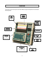
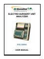
ELECTRO-SURGERY UNIT
ANALYZER
ESU-2000A
USER MANUAL
BC BIOMEDICAL
ESU-2000A
TABLE OF CONTENTS
DESCRIPTION.............................................................................................................
3
OVERVIEW..................................................................................................................
4
SAFETY PRECAUTIONS ............................................................................................
5
OPERATING INSTRUCTIONS ....................................................................................
6
MANUAL REVISIONS..................................................................................................
9
WARRANTY.................................................................................................................
9
SPECIFICATIONS ....................................................................................................... 10
NOTES......................................................................................................................... 12
1
WARNING
All connections to patients must be removed before
connecting the Device Under Test (DUT) to the
Analyzer. A serious hazard may occur if the patient
is connected when testing with the Simulator.
Do not connect any leads from the patient directly to
the Analyzer or DUT.
CAUTION
Always turn the ESU under test off before making or
removing connections. Never touch exposed
metal surfaces on test leads or other current
carrying parts while ESU is activated. Never open
the ESU-2000A when connected to an ESU.
Electro-Surgery units generate
high frequency/RF voltages at high levels.
NOTICE
BC GROUP INTERNATIONAL, INC. RESERVES THE RIGHT
TO MAKE CHANGES TO ITS PRODUCTS OR
SPECIFICATIONS AT ANY TIME, WITHOUT NOTICE, IN
ORDER TO IMPROVE THE DESIGN OR PERFORMANCE AND
TO SUPPLY THE BEST POSSIBLE PRODUCT. THE
INFORMATION IN THIS MANUAL HAS BEEN CAREFULLY
CHECKED AND IS BELIEVED TO BE ACCURATE. HOWEVER,
NO RESPONSIBILITY IS ASSUMED FOR INACCURACIES.
Manual ESU-2000A
www.bcgroupintl.com
10/05
Copyright © 2005
Made in the USA
Rev 02
2
BC GROUP
ESU-2000A
ELECTRO-SURGERY UNIT ANALYZER
The Model ESU-2000A is a precision Electro-Surgery Unit Analyzer (ESU). It tests the RF
power output of Electro-Surgery Units. The power reading is taken from a large 4 ½ inch
analog display. It offers six resistive loads for RF power testing from 50 to 500 ohms, along
with a 200 ohm load for RF leakage current testing. The patient return electrode resistance
simulation is adjustable in one ohm increments from 0 to 999 ohms.
The following are highlights of some of the main features:
•
•
•
•
•
•
•
•
•
•
LARGE 4 ½ INCH ANALOG DISPLAY
+/- 5% OF FULL SCALE ACCURACY
RETURN CONTACT MONITOR TEST
RF LEAKAGE TEST
PORTABLE
OSCILLOSCOPE ISOLATED OUTPUT
0-10 MHz BANDWIDTH
EASY OPERATION
ACCESSORY KIT INCLUDED
HIGH IMPLACT PLASTIC ENCLOSURE
3
OVERVIEW
This section looks at the layout of the ESU-2000A and gives descriptions of the elements
that are present.
FWH
0.5 AMP
Fast Blow
Fuse
4 ½ INCH
ANALOG
DISPLAY
Patient Plate
Return
Electrode
Monitor Test
Oscilloscope
Isolated Output
Potentiometer
Ohms
RF Leakage
Input
ESU Power
Ohms/Load
&
Watts Full Scale
Carrying
Handle
Switching Module
ESM-1
RF Leakage Testing
&
ESU Power Testing
4
ESU
Ground
SAFETY PRECAUTIONS
CAUTION
Electro-Surgery Units (ESUs) produce high frequency/RF output
voltages up to 500 volts.
CAUTION
Always turn the ESU under test Off before making
or removing connections.
CAUTION
Never touch exposed metal surfaces on test leads or other currentcarrying parts while the ESU is activated.
CAUTION
Refer to ESU manufacturer’s manuals and specifications for safety and
testing information.
CAUTION
Only replace the ESU-2000A fuse with the specified rating and type.
CAUTION
Never open the ESU-2000A case when it is connected to an ESU.
5
OPERATING INSTRUCTIONS
ESU RF Power Measurements
1. Consult the ESU manufacturer’s manual for load specifications.
2. Turn off ESU under test. Remove all connections between the ESU under test and the
ESU-2000A.
3. Install the BC Biomedical Switching Module on the ESU-2000A front panel so that the
words “ESU Power Testing” are right-side-up. When installed correctly, the Active Electrode
connectors should be exposed, and the RF Leakage connectors should be inaccessible.
4. Connect the ESU’s Patient Plate to the ESU-2000A’s black Patient Plate connector using
a black test lead.
5. Connect the ESU’s Active Electrode to the ESU-2000A’s desired load range connector in
the Active Electrode area, on the left side of the front panel. The Active Electrode input
connectors are color coded, and each corresponds to a color-coded range on the analog
meter. The full-scale watts range for each range equals the input resistance. For example,
the 50 ohms input resistance range has a full-scale watts range of 50 watts, etc.
6. Turn the controls on the ESU under test to minimum power, and then activate the CUT
or COAG modes. Turn the ESU power to the desired levels, being careful to not exceed the
full-scale wattage range selected on the ESU-2000A. Note the reading on the ESU-2000A
on the proper color-coded wattage range, and record it if desired. If the milliamp output,
rather than watts, is required, that reading may be obtained by reading the lower 0-1000
milliamp scale.
7. Turn the ESU power to minimum and deactivate the output before disconnecting from
ESU-2000A, or before moving the Active Electrode test lead to a different input range
connector.
6
ESU RF Leakage Current Measurements
1. Turn off ESU under test. Remove all connections between the ESU under test and the
ESU-2000A.
2. Install the BC Biomedical Switching Module on the ESU-2000A front panel so that the
words “RF Leakage Testing” are right side up. When installed correctly, the Active
Electrode connectors should be inaccessible, and the RF Leakage connectors should be
exposed.
3. Connect the ESU’s Active Electrode to the ESU-2000A’s red RF Leakage connector
using a red test lead. DO NOT MEASURE ACTIVE ELECTRODE LEAKAGE ON NONISOLATED ESUs with the ESU-2000A. Damage may occur to the ESU-2000A.
4. Connect the ESU’s case ground to the ESU-2000A’s green ESU Ground connector using
a green test lead.
5. Turn the controls on the ESU under test to minimum power, then activate the CUT or
COAG modes. Turn the ESU power to the desired level. Note the Active Electrode RF
Leakage current reading on the ESU-2000A’s red 0-500 milliamps RF Leakage scale, and
record it if desired.
6. Turn the ESU power to minimum and deactivate the output.
7. Move the red test lead to the Patient Plate connection on the ESU under test. Leave the
ground connection in place.
8. Turn the controls on the ESU under test to minimum power, then activate the CUT or
COAG modes. Turn the ESU power to the desired level. Note the Patient Plate RF leakage
current reading on the ESU-2000A’s red 0-500 milliamps RF Leakage scale, and record it
if desired.
9. Turn the ESU power to minimum and deactivate the output. Disconnect all test leads.
7
Patient Plate Return Electrode Monitor Test
1. Turn off ESU under test. Remove all connections between the ESU under test and the
ESU-2000A.
2. Use an actual return electrode monitor patient plate connected to the ESU under test.
Cut off the plate and expose the two wires.
3. Connect both wires to the two ESU-2000A Patient Plate Return Electrode Monitor Test
jacks in the upper right corner via test leads of any color with alligator clips.
4. Apply power to the ESU under test, and verify operation of its return electrode monitor
mode, as specified by the ESU manufacturer, using various “Ohms” settings on the ESU2000A.
5. Turn off power to the ESU under test, and remove all connections.
8
MANUAL REVISIONS
Revision #
Engineering #
Revisions Made
Rev 01
DT7375
New Manual Format
Rev 02
DT7375
Accessory Fuse Updated
LIMITED WARRANTY
WARRANTY: BC GROUP INTERNATIONAL, INC. WARRANTS ITS NEW PRODUCTS TO BE FREE
FROM DEFECTS IN MATERIALS AND WORKMANSHIP UNDER THE SERVICE FOR WHICH THEY
ARE INTENDED. THIS WARRANTY IS EFFECTIVE FOR TWELVE MONTHS FROM THE DATE OF
SHIPMENT.
EXCLUSIONS: THIS WARRANTY IS IN LIEU OF ANY OTHER WARRANTY EXPRESSED OR
IMPLIED, INCLUDING, BUT NOT LIMITED TO ANY IMPLIED WARRANTY OF MERCHANTABILITY
OR FITNESS FOR A PARTICULAR PURPOSE.
BC GROUP INTERNATIONAL, INC. IS NOT LIABLE FOR ANY INCIDENTAL OR CONSEQUENTIAL
DAMAGES.
NO PERSON OTHER THAN AN OFFICER IS AUTHORIZED TO GIVE ANY OTHER WARRANTY OR
ASSUME ANY LIABILITY.
REMEDIES: THE PURCHASER'S SOLE AND EXCLUSIVE REMEDY SHALL BE: (1) THE REPAIR OR
REPLACEMENT OF DEFECTIVE PARTS OR PRODUCTS, WITHOUT CHARGE. (2) AT THE OPTION
OF BC GROUP INTERNATIONAL, INC., THE REFUND OF THE PURCHASE PRICE.
9
SPECIFICATIONS
ESU-2000A
Display
4-1/2” analog meter
Meter accuracy is +/- 2.0 % of full scale
Color-coded scales in Watts and Milliamps
Selectable Loads & Ranges
50, 100, 200, 300, 400, & 500 ohms, non-inductive
Each range’s ohms load value corresponds to its
full-scale watts value
(Example: 50 ohms => 50 watts)
Load accuracy is +/- 2.0 %
Watts Measurement Accuracy
+/- 5% of full scale
Frequency Response
0-10MHz
ESU Output Current Range
0-1000 mA for all ranges
RF Leakage Test
500 mA maximum into 200 ohm load,
non-inductive
Return Contact Monitor Test
Digital display
0-999 ohms
1 ohm resolution
Minimum resistance at
“zero” setting
3 ohms
3% accuracy
Oscilloscope Output
Isolated & uncalibrated
Fuse
FWH-1/2 0.5 amp fast blow
Case, Size, & Weight
High impact plastic enclosure
4.125” H x 8.4” W x 9.1” D
4 pounds net weight
10
Accessories Included
Qty.
1
1
1
4
2
1
1
1
1
Optional Accessories
Carrying Case
Accessory
Red test lead
Black test lead
Green test lead
Alligator clips
Red clip insulators
Black clip insulators
Spare fuses
User manual
ESM-1 Switching Module
P:\MANUALS\BCGroup\…\ESU-2000A\ESU-2000A_UM_Rev02.doc
11
NOTES
12