1
SHORT DESCRIOPTION ICP 100
TABLE OF CONTENTS
ICP 100
KB_ICP 100_E_V300.doc
Gantner Instruments Test & Measurement GmbH
Vers.-Nr. 300
0
SHORT DESCRIOPTION ICP 100
KB_ICP 100_E_V300.doc
Gantner Instruments Test & Measurement GmbH
1
SHORT DESCRIOPTION ICP 100
Copyright 2004 by Gantner Instruments Test & Measurement GMBH, Schruns (Austria).
Copyrights: Operating instructions, manuals and software are protected by copyright ©. All rights are reserved.
Copying, duplication, translation, installation in any electronic medium or machine-readable form in whole or in part is
prohibited. The sole exception is represented by creation of a back-up copy of software for own use as a safeguard, so
far as this is technically possible and recommended by us. Any infringement will render the party committing such
infringement liable to compensation payment.
Liability: Any claims against the manufacturer based on the hardware or software products described in this manual
shall depend exclusively on the conditions of the guarantee. Any further-reaching claims are excluded, and in
particular the manufacturer accepts no liability for the completeness or accuracy of the contents of this manual. The
right is reserved to make alterations, and alterations may be made at any time without prior notice being given.
Trade marks: Attention is drawn at this point to markings and registered trade marks used in this manual, in
particular to those of Microsoft Corporation, International Business Machines Corporation and Intel Corporation.
!
Important: Before commencing installation, commissioning, putting into service and before any
maintenance work is carried out, it is essential that the relevant warning and safety instructions in this
manual are read!
KB_ICP 100_E_V300.doc
Gantner Instruments Test & Measurement GmbH
2
SHORT DESCRIOPTION ICP 100
TABLE OF CONTENTS
CONTENTS:
1.
CONTENTS OF THE DEMO KIT.........................................................................................................................4
2.
INSTALLING THE HARDWARE ........................................................................................................................4
3.
INSTALLING THE CONFIGURATION SOFTWARE ...........................................................................................5
4.
4.1.
4.2.
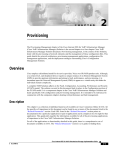
FIRST STEPS ....................................................................................................................................................5
Starting the DEMO-Version: ................................................................................................................................. 6
Starting of the licensed version: ........................................................................................................................... 8
5.
DESCRIPTION OF THE USER INTERFACE .....................................................................................................10
6.
6.1.
6.2.
6.3.
CONFIGURATION OF THE MODULES ............................................................................................................13
Creating a new configuration: ............................................................................................................................ 13
Configuration handling: ..................................................................................................................................... 16
Saving the configuration:................................................................................................................................... 16
7.
CONNECTING SEVERAL MODULES ...............................................................................................................17
8.
8.1.
8.2.
8.3.
ERRORS AND CAUTIONS...............................................................................................................................19
No modules are found: ...................................................................................................................................... 19
Flashing of the red ERR-LED: ............................................................................................................................. 19
Loss of the configuration / program:................................................................................................................... 19
9.
9.1.
9.2.
9.3.
EXAMPLES......................................................................................................................................................21
Measurement of the temperature: ...................................................................................................................... 21
Measurement of the weight: .............................................................................................................................. 23
Measurement of flow:........................................................................................................................................ 25
KB_ICP 100_E_V300.doc
Gantner Instruments Test & Measurement GmbH
3
SHORT DESCRIOPTION ICP 100
CONTENTS OF THE KIT / HARDWARE
1.
CONTENTS OF THE DEMO KIT
□
□
□
□
□
□
2.
ISM 111 Intelligent Sensormodul
ISK 200 Interface converter
ICP 100 Configuration software
ISM SSB Sensor-Simulations-Board
interconnecting cables
Software manual
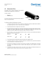
INSTALLING THE HARDWARE
The bus interface of the Sensor Module is based on the RS-485-Standard. As the master computer usually is equipped with a
RS-232-Interface an interface converter has to be used, the ISK 200, which is a desktop model. This ISK 200 needs a 220V
power-supply.
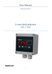
Safeguarding
at the back side
Power: green LED
Receive: yellow LED
Transmit: yellow LED
Switch for the bus termination
The ISK100 is connected to the master computer via a serial interface. As soon as the ISK 200 is power-supplied the PowerLED is shining.
If the LED is still dark, it could be caused by the following reasons:
□
□
□
The power-supply is interrupted.
The safeguarding is damaged and has to be replaced.
If point 1 and 2 are not true, the ISK 200 is damaged and has to be replaced.
Afterwards the ISK 200 has to be connected to the ISM 111 / e.bloxx A1-1 with an interface-cable (4 contacts), fixed on the
upper side of the module. Now the green LED (RUN) of the ISM111 is lighted and the red LED (ERR) could be flashing.
Last but not least the Sensor-Simulations-Board has to be connected to the ISM 111 / e.bloxx A1-1 at the lower side of the
module.
KB_ICP 100_E_V300.doc
Gantner Instruments Test & Measurement GmbH
4
SHORT DESCRIOPTION ICP 100
INSTALLING THE SOFTWARE
3.
INSTALLING THE CONFIGURATION SOFTWARE
The ICP 100 is the required software to configure all the modules of the series ISM 100, IDL 100, e.bloxx and Q.bloxx.
Now the installation of the software ICP 100 is being
described step by step:
Start the installation by typing a:\setup.exe
The further steps for the installation of the software are being described online.
The configuration software is available as DEMO-version and as licenced version.
ICP 100 - DEMO:
With the DEMO-Version you can create configurations but it is not possible to write data into the module. You only can read
data out of the module.
ICP 100 - Advanced:
The Configuration Software ICP100 as a licenced version provides full functionality. For data loggers the modem
communication is supported and the Profibus-DP protocol is supported as well for all the modules which are capable of this
protocol (all except data loggers). It also contains the required GSD-Files and Type-files for the connection with Profibussystems.
KB_ICP 100_E_V300.doc
Gantner Instruments Test & Measurement GmbH
5
SHORT DESCRIOPTION ICP 100
FIRST STEPS
4.
FIRST STEPS
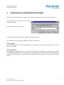
After hardware and software have been installed, you have to start the program. The first time you do this, several settings
have to be done. The next time you start you will get to the working platform automatically.
At the beginning you will be asked to choose the
language you want to work with. 3 languages (English,
French and German) are available. Mark the right one
and confirm with "OK".
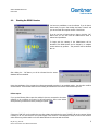
The following interfaces are available:
□ RS232 - Direct
□ RS232 - Standard modem
□ RS232 - RF-Modem
□ TCP-IP Socket
To work with the DEMO-Kit select "RS232 - Direct".
As ComPort select an interface, which has not, been used yet.
Remark: The mouse is already connected to one of these
interfaces!
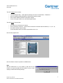
After all the communication settings have been done - you can change them afterwards, too ("Communication" and "
Parameters..." in the menu bar) - a window appears, where you are asked about the license.
KB_ICP 100_E_V300.doc
Gantner Instruments Test & Measurement GmbH
5
SHORT DESCRIOPTION ICP 100
FIRST STEPS
4.1.
Starting the DEMO-Version:
You have two possibilities to use the software. If you do have a
license-code you type it after clicking the button "License" and
you can work with the complete version of the ICP100.
If you do not have a license-code you have to click the "OK"button and you can work with the DEMO-Version which is
reduced in its possibilities.
To begin with the starting of the DEMO-Version will be
described. This DEMO-Version can be changed to a complete
version without any problem. - This procedure will be described
later on.
After clicking the "OK"-button you will be informed that the sensordatabase has been installed:
During the initialization of the program the software automatically searches for an available module - but there also could be
several modules. These modules will be shown including the transmission rate and the communications protocol.
Failure report:
If you get the following failure report the module/s is/are not connected to the master
computer or the connection is incorrect. In this case watch the LEDs at the ISK100
when performing a manual bus-scan by clicking the symbol:
If the green "RUN"-LED on the module does not shine, please check whether the green "POWER"-LED at the converter ISK100
is shining or not. If it does not there is no power supply of the converter or the safeguard is faulty. As soon as the converter
works without any problem watch out for the cables between the converter and the module.
KB_ICP 100_E_V300.doc
Gantner Instruments Test & Measurement GmbH
6
SHORT DESCRIOPTION ICP 100
FIRST STEPS
The LED "Transmit" does not shine:
□
□
□
□
The COM-setting is faulty → check again the settings in the menu "Communication", "Parameters..."
there are interface problems between the ISK100 and the master computer
there could be hardware problems at the master computer
if none of the upper causes is true, the ISK100 might be defect
The LED "Receive" does not shine:
□
□
□
the module is not connected to the system
the bus connection is incorrect → check the bus connection at the module and at the ISK100 ( A → A; B → B)
the module's interface might be faulty.
In this case please contact your Gantner-representative next to you.
Now the main program starts:
Now the software is ready for operation as a DEMO-Version.
Hint:
With the DEMO-Version it is not possible to write data into the
module. You only can read data from the module. If you try to write
anyway you will find the following message:
KB_ICP 100_E_V300.doc
Gantner Instruments Test & Measurement GmbH
7
SHORT DESCRIOPTION ICP 100
FIRST STEPS
4.2.
Starting of the licensed version:
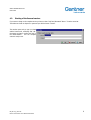
If you want to change to the complete version you have to select "Help" and afterwards "About..." from the menu bar.
The window as shown in chapter 4.1 opens and you click the button "License".
The window opens and you type your data
and the license-code, confirming with "OK".
Once again you have to confirm with "OK" in
the license-window - now the complete
version is ready to use!
KB_ICP 100_E_V300.doc
Gantner Instruments Test & Measurement GmbH
8
SHORT DESCRIOPTION ICP 100
DESCRIPTION OF THE USER INTERFACE
5.
DESCRIPTION OF THE USER INTERFACE
Before describing all the different settings the most important buttons of the menu bar should be mentioned:
Open a new file
Printing the proper settings
Open an existing file
Software controlled changing of the instrument
from the configuration mode to the operating mode
(Profibus-DP) after finishing the con-figuration
Save the configuration
Manual bus scan
Send the configuration to the module
As soon as a module is detected the following possibilities of configuration are shown in 4 different menus. But the ISM101 is
an exception, the menus "Info" and "Measure" are shown as a common menu.
The menu "Infos" contains information about the
□
□
□
□
□
□
□
□
□
Module Type
Serial number
Vendor
HW-Revision
SW-Revision
Address
Protocol
Baudrate
Character Format
of the connected module.
KB_ICP 100_E_V300.doc
Gantner Instruments Test & Measurement GmbH
10
SHORT DESCRIOPTION ICP 100
DESCRIPTION OF THE USER INTERFACE
In the menu "Measure" you can find the current
values and in the setpoint-channel the proper values
can be entered.
But before you can do this all the variables have to be
defined and sent to the module.
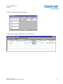
In the menu "Variable Settings" all the individual channels are configured. The module configurations are listed in a table
channel by channel. The input and output channels can be defined and named, the type of measurement and the range can be
defined, too.
KB_ICP 100_E_V300.doc
Gantner Instruments Test & Measurement GmbH
11
SHORT DESCRIOPTION ICP 100
DESCRIPTION OF THE USER INTERFACE
In the menu "Module Settings" several settings can be
done concerning the whole module, e.g. address of the
module, the character format, the Baudrate, the Loggerfunctions of the Data Logger, the Update Time, and so
on...
KB_ICP 100_E_V300.doc
Gantner Instruments Test & Measurement GmbH
12
SHORT DESCRIOPTION ICP 100
CONFIGURATION OF THE MODULES
6.
CONFIGURATION OF THE MODULES
6.1.
Creating a new configuration:
To create a new configuration select "File" and "New File" from the menu or click the following button:
On the screen you will find the window:
As a default setting the e.bloxx A1-1 is being
shown on the screen. To define a configuration
for the required module type you have to select
the module type which fits best to your
application in the “Module Settings”.
Refer to the following picture:
The inputs in these fields are independent from
the selected interface!
KB_ICP 100_E_V300.doc
Gantner Instruments Test & Measurement GmbH
13
SHORT DESCRIOPTION ICP 100
CONFIGURATION OF THE MODULES
Now you can configure the selected module in the menu "Variable Settings". The following picture shows you an example
together with further information about the different fields:
To start configuration click the corresponding field and you can choose from several proposals.
Channel-Type: Each row in this table is corresponding with one channel. There are different kinds of channel-types:
□
□
□
Analog Input
Analog Output
Digital Input
□
□
□
Digital Output
Arithmetic
Alarm
□
□
PID Controller
Setpoint
In the field Variable Name for each channel a designation with max. 20 characters can be given.
In the column Sensor appears the designation of the connected sensor for the analog and digital sensor variables. The sensor
can be selected from a list concerning the measurand and the principle of measurement. Also customized sensors can be
defined in this field. The field remains empty when no sensor is connected to the channel.
In the column Type of Measurement the kind of measurement is selected: resistant measurement in 2-, 3- or 4-wire
technology, voltage measurement "single ended" or "differential", etc.
The columns Connection and Terminals display how the selected sensor has to be connected to the sensor module. This
might be important for documentation purposes.
In the column Format the format for the data-transmission via the bus is indicated. For the transmission and representation
as an ASCII-string the unit, section length and number of decimals are indicated. For the transmission in binary format the
indications Boolean, Integer or Real are indicated in addition to these. The data format is shown in the column as a formatstring with decimal point and unit.
In the column Range/Error the range limits for the test value recordings are entered. Depending on the range an optimum
amplification of the signal is selected automatically. In addition the error handling of the Analog Input Variable and the Digital
Output Variable can be defined. The sensor modules recognize violations of limiting values, communication time-outs and
breakages of the sensor as errors. For Controller Variables the P-, I- and D-parts and for Analog Output Variables the output
ranges can be defined.
In the column Additionals various functions for the individual sensor variables can be defined. With the Analog Sensor
Variables you can choose between two types of filters, a digital low-pass for the suppression of higher-frequency photoelectric
noise levels and an arithmetic signal averager for increasing the measuring accuracy. With the Digital Sensor Variables an
indication of the time base is required with time-controlled inputs/outputs (frequency measurements and PWM). For the digital
counter inputs a conversion factor can be indicated to multiply the counted measurand if necessary. For the Digital Output
KB_ICP 100_E_V300.doc
Gantner Instruments Test & Measurement GmbH
14
SHORT DESCRIOPTION ICP 100
CONFIGURATION OF THE MODULES
Variables and the Alarm Variables threshold values can be indicated to trigger the output. Furthermore the setup of a
Controller Variable can be defined here and a variable can be related to an Analog Output Variable.
The column Profibus-DP Configuration appears, if the Profibus-DP Protocol is used. Different formats for data transmission
can be selected to realize the connection to a higher-ranking system (no matter whether PC or SPC) as easily as possible.
This new configuration has to be saved, clicking "File" and "Save to File" in the menu bar. Now this configuration has to be
sent to the module, too. Select "File" and "Send to Module as" from the menu bar.
The window shown next appears and you have to select the module to
which the configuration has to be sent.
Important: The module-type of the new configuration has to be equal to
the module-type it has to be sent to!!!
After confirming with "OK" you will be asked once again if you really want
to replace the current configuration in the module:
Now you will find the window where you have the possibility to select between Info / Measure / Variable Settings / Module
Settings.
KB_ICP 100_E_V300.doc
Gantner Instruments Test & Measurement GmbH
15
SHORT DESCRIOPTION ICP 100
CONFIGURATION OF THE MODULES
6.2.
Configuration handling:
As soon as you change to the register card "Variable Settings" you can redefine the configuration as being described before.
After having finished the variable settings the data have to be sent into the
module. This happens by opening the menu "Measure" and confirming the
shown box on the right side or by clicking the download button
.
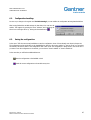
6.3.
Saving the configuration:
In the menu "File" there are several possibilities to save the configuration. Some of these already were shown in chapter 6.1.
The configuration can be saved either to the harddisk/disk or directly to the sensor module. In "Save to File as" you can select
the directory and the file name of the configuration. With "Save to file" the configuration is being saved to the current file. If
you want to save the configuration to the module, you can choose "Send to Module" or "Send to Module as".
In the menu bar you will find two additional buttons:
Save the configuration to the harddisk or disk.
Send the current configuration to the module at any time.
KB_ICP 100_E_V300.doc
Gantner Instruments Test & Measurement GmbH
16
SHORT DESCRIOPTION ICP 100
CONFIGURATION OF THE MODULES
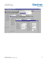
7.
CONNECTING SEVERAL MODULES
If several modules are connected at the same time, only the module with the lowest address is shown in the menu-window.
menu bar
Notice that all modules have the same default-address (001) at the beginning. Therefore all the modules have to get a new
address not equal to the default one and different from each other.
The necessary steps therefore are described now:
1.
2.
3.
Connect only one module
Execute a bus scan by clicking the button
Select "Module Settings"
4.
5.
Select a new address (e.g. 2) in the "Address-field
The new configuration has to be sent to the module by clicking the button
in the menu bar.
After each module has got its own address e.g. all of them can be connected with the connector ICM 100 to work on a
common field-bus (refer to the user's manual).
To complete this procedure a bus scan has to be performed. →
Now the software should detect all of the modules and on clicking the respective window or selecting one module from the
menu window all the modules can be configured in any sequence.
You can search for new modules by clicking the "bus scan"-Symbol at any time!
KB_ICP 100_E_V300.doc
Gantner Instruments Test & Measurement GmbH
17
SHORT DESCRIOPTION ICP 100
CONFIGURATION OF THE MODULES
KB_ICP 100_E_V300.doc
Gantner Instruments Test & Measurement GmbH
18
SHORT DESCRIOPTION ICP 100
ERRORS AND CAUTIONS
8.
ERRORS AND CAUTIONS
As not all of the errors and cautions could have been mentioned before, some of them are described in the following parts:
8.1.
No modules are found:
Refer to chapter 4.1
8.2.
Flashing of the red ERR-LED:
The ERR-LED at the front side of the module has several functions and not all of them are error-functions. For detailed
informations refer to the user manual.
ERR-LED is shining continuously:
□ There is an error of the sensor which could be caused by:
□ a faulty configuration
□ a breakage of a sensor or a short-circuit of the line
□ an exceeding of the range
ERR-LED is blinking:
□ the module has not been inquired for a certain period of time, the communication-timeout is active. This one can be
defined in "Module Settings" at the Timeout-field.
8.3.
Loss of the configuration / program:
The software of the sensor module can be destroyed due to incorrect operation or extreme EMC load, higher than the
permitted limit. In this case the configuration program cannot find the module despite correct connections and signal or
power-lines.
In this case - but also in case of a firmware-update - a new download to the module has to follow. Therefore click "Utilities" in
the menu bar and then "Download" - "Firmware".
On the screen you will find the following message:
Confirm with „OK".
KB_ICP 100_E_V300.doc
Gantner Instruments Test & Measurement GmbH
19
SHORT DESCRIOPTION ICP 100
ERRORS AND CAUTIONS
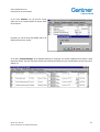
In the following window all of the installed modems are listed. Select the module
for the download. If no module is listed or the module you are looking for is not
available, click the button "NEW".
Now a new module can be defined.
Usually you will find the following message on the screen. Please confirm.
Now you have to switch on and off the selected module.
As soon as all of these things are done a new window appears which shows you different download-files.
Select the file that corresponds to the desired protocol
and the module will be loaded automatically. This
takes about 1 to 2 minutes.
Now the module can be configured once again.
KB_ICP 100_E_V300.doc
Gantner Instruments Test & Measurement GmbH
20
SHORT DESCRIOPTION ICP 100
EXAMPLES
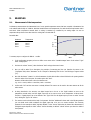
9.
EXAMPLES
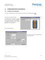
9.1.
Measurement of the temperature:
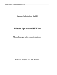
In laboratory measurements the characteristic line of a very special temperature-sensor has been recorded. A linearization has
to be realized with the help of a ISM111. With this linearized sensor the temperature of a tank should be kept between 160°C
and 180°C. When temperature exceeds 180°C a cooling is switched on, controlled by an analog output. As soon as
temperature drops down to less than 160°C the cooling has to be switched off.
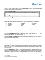
Recorded data:
Temperature
145 °C
180 °C
200 °C
210 °C
200
Grad °C
Resistance
1100 Ω
2300 Ω
2900 Ω
3700 Ω
250
150
100
50
0
110
7 necessary steps to configure the ISM111 - module:
230
290
370
Ohm
1.
In the configuration-program you have to define a new sensor in the "Variable Settings"-menu. In the column "Type"
select "Analog Input".
2.
Click into the column "Sensor", select the button "New" and type the sensor's name.
3.
Now you will be asked for a description, the principle of measuring and the unit. Describe the sensor in the
"Description"-field, select "Resistance" in the "Principle of Measuring"-field. In the "Unit"-field type "Degree Celsius
[°C]".
4.
Now click the button "Lineariz." to do the linearization. Double-click the blue-colored field and in the opening window
enter the values of the first point. For another point click "New".
Attention: All the values have to be in the absolute unit!
e.g.: 1mV = 0.001V; 1kOhm = 1000 Ohm; 1mA = 0.001A etc.
5.
Confirm with "OK" and the new sensor is already defined. The sensor can be used in the same manner as all the
other sensors.
6.
As being described in the exercise, one digital output has to be set to the "High"-condition as soon as the
temperature exceeds 180°C and the digital output has to be reset as soon as the temperature is below 160°C.
Therefor a "Digital Output" has to be defined in the "Type"-field. For the digital output you have to select "Process
Out", clicking the "Type of M." column.
7.
The exercise can be solved with the help of a hysteresis. Click the "Additionals"-column and in the following window
you can decide under which conditions the digital output has to be set to a certain condition. The necessary
hysteresis for this example is called "High Non Failsafe". In the "Source"-field select the channel the characteristic of
the digital output depends on. With "Value1" the first boundary is defined. "Value2" informs you about the width of
the hysteresis.
KB_ICP 100_E_V300.doc
Gantner Instruments Test & Measurement GmbH
21
SHORT DESCRIOPTION ICP 100
EXAMPLES
The window for the hysteresis should look like this:
The main-window "Variable Settings" shows the whole configuration:
KB_ICP 100_E_V300.doc
Gantner Instruments Test & Measurement GmbH
22
SHORT DESCRIOPTION ICP 100
EXAMPLES
9.2.
Measurement of the weight:
A weighing machine for a lorry should be equipped. When
the lorry does not move the weight should be set equal to
zero. Now the lorry may be loaded and this weight should
be read from a special place.
The application needs 2 weighing-sensors with a bridge in
4-wire-technic. The addition of these two sensors is equal
to the total weight of the load. The zero adjustment should
be possible by pressing a button near the weighingmachine.
Technical data for the weighing-sensors:
0V
1V
0 kg
10.000 kg
To configure the module the followings steps are necessary:
1.
To measure the weight two "Analog Input"-channels have to be defined in the "Variable Settings"-menu. Therefore
click into the "Type"-column. Select "Bridge" in the "Sensor"-column.
2.
The maximum weight to be measured is 20000kg. Therefore you have to define five-digit numbers before the comma
as an output-format in the "Format"-field. The output unit should be kg which you define in the "Unit"-field.
3.
The zero adjustment for the measuring-bridges has to be done in the "Range/Error"-field. In the upper part of the
window the range can be defined, in the lower part you have to define how the "Zero Calibration" should be done.
Host
Dig. IO1
Dig. IO2
On Variable result
KB_ICP 100_E_V300.doc
Gantner Instruments Test & Measurement GmbH
23
SHORT DESCRIOPTION ICP 100
EXAMPLES
4.
With "Host" the computer does the zero adjustment. In this example select the first digital input to do the zero
adjustment with a push-button. With "On variable result" the zero adjustment can be done by anyone of the defined
channels.
5.
To calculate the total weight an "Arithmetic"-channel has to be defined in the "Type"-field. The formula for this
addition has to be written in the "Additionals"-field. The output-format does not change.
The main-window "Variable Settings" shows the whole configuration:
KB_ICP 100_E_V300.doc
Gantner Instruments Test & Measurement GmbH
24
SHORT DESCRIOPTION ICP 100
EXAMPLES
9.3.
Measurement of flow:
The quantity of flow in a pipe with a diameter of 20cm should be
calculated with an intelligent sensor module ISM 111.
You have to measure:
□
□
filling level
velocity of the flow
filling level
The module should calculate the flow-surface and the quantity of
flow out of the measured values.
velocity of the flow
To configure the module the following steps are necessary:
1.
To measure the filling level and the velocity of the flow two analog input channels are needed which are defined in
the "Variable Settings"-menu. Click the "Type"-field and select "Analog Input".
2.
For both measurements select "Voltage" in the "Sensor"-field.
3.
The output-format has to be defined in the "Format"-field. "Field Length" is the number of digits inclusive the comma.
"Precision" is the number of digits right of the comma. The output-format is defined in the "Unit"-field. In this
example we only need two digits left and one right of the comma. The units are cm and m/s.
4.
Now the conversion of Volt to the necessary format has to be done. You have to enter the minimum and maximum
values in the "Conversion"-field. These are:
Filling level:
0%
0V
at
0cm
100%
10V
at
20cm
velocity of flow:
0%
100%
0V
10V
at
at
0m/s
10m/s
5.
To get a better precision the measurement-range can be limited in the "Range/Error"-field.
6.
To calculate the width of the surface an "Arithmetic"-channel has to be defined in the "Type"-field. The format and
the unit are defined in the "Format"-field. The unit is cm.
7.
The formula for the calculation of the width of the surface has to be added to the "Additionals"-field. The channels
and functions for the calculation are shown as buttons. When clicking them, they are placed to the formula
automatically.
8.
To calculate the flow-surface continue as shown in step 6 and 7. At the end the two arithmetic values have to be
multiplied in another "Arithmetic"-channel to get the result of the quantity of the flow.
KB_ICP 100_E_V300.doc
Gantner Instruments Test & Measurement GmbH
25
SHORT DESCRIOPTION ICP 100
EXAMPLES
Here is the formula for the calculation of the surface:
A = h/(6s) x (3h2 + 2s2)
r
h
s = 2 x √(h x(2r-h))
r = 10 cm
s
The main-window "Variable Settings" shows the whole configuration:
KB_ICP 100_E_V300.doc
Gantner Instruments Test & Measurement GmbH
26
SHORT DESCRIOPTION ICP 100
EXAMPLES
KB_ICP 100_E_V300.doc
Gantner Instruments Test & Measurement GmbH
27
www.gantner-instruments.com
GANTNER Instruments Test & Measurement GmbH
Montafonerstraße 8 • A-6780 Schruns/Austria
Tel.: +43 (0)5556-73784-410 • Fax: +43 (0)5556-73784-419
E-Mail: [email protected]