1
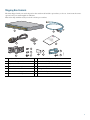
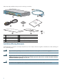
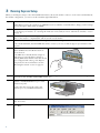
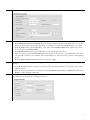
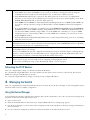
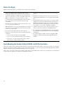
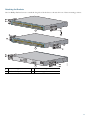
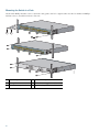
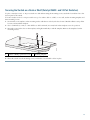
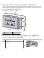
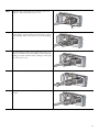
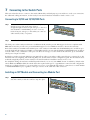
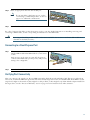
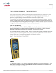
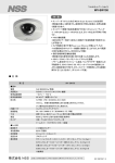
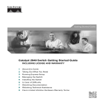
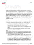
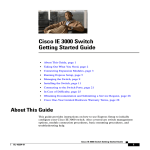
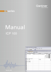
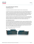
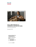
GETTING STARTED GUIDE
Catalyst 3560 Switch Getting Started Guide
1
About this Guide, page 2
2
Taking Out What You Need, page 2
3
Running Express Setup, page 6
4
Managing the Switch, page 8
5
Installing the Switch, page 9
6
Securing the AC Power Cord (Catalyst 3560 8- and 12-Port Switches), page 14
7
Connecting to the Switch Ports, page 16
8
In Case of Difficulty, page 18
9
Obtaining Documentation and Submitting a Service Request, page 19
10 Cisco Warranty Information, page 20
1 About this Guide
This guide provides instructions on how to use Express Setup to configure your switch. It also includes information about switch
management options, basic rack-mounting procedures, port and module connections, power connection procedures, and
troubleshooting help.
For additional installation and configuration information for Catalyst 3560 switches, see the Catalyst 3560 documentation on
Cisco.com. For system requirements, important notes, limitations, open and resolved bugs, and last-minute documentation
updates, see the release notes, also on Cisco.com.
When you use the online publications, refer to the documents that match the Cisco IOS software version running on the switch.
The software version is on the Cisco IOS label on the switch rear panel.
For translations of the warnings that appear in this publication, see the Regulatory Compliance and Safety Information for the
Catalyst 3560 Switch guide.
2 Taking Out What You Need
1. Unpack and remove the switch and the accessory kit from the shipping box.
2. Return the packing material to the shipping container, and save it for future use.
3. Verify that you have received the items shown on page 3. If any item is missing or damaged, contact your Cisco
representative or reseller for instructions. Some switch models might include additional items, and you might need to supply
or to order some optional items.
Equipment That You Supply to Run Express Setup
You need to supply this equipment:
• PC
• Ethernet (Category 5) straight-through cable (as shown)
2
Shipping Box Contents
The items shipped with your switch depend on the switch model and the options that you choose. Some items shown are
optional, and your switch might look different.
These items ship with the Catalyst 3560 24- and 48-port switches:
1
SYST
RPS
1X
STAT
DUPLX
SPEED
PoE
MODE
2
3
4
5
6
7
8
9
10
11
12
13
14
15
16
17
15X 17X
18
19
20
21
22
2X
23
24
25
26
27
28
29
30
31
32
33
31X 33X
34
35
36
37
38
16X 18X
39
40
41
42
43
44
45
46
47
Catalyst 3560G
48
SERIES
PoE-48
47X
32X 34X
49
51
48X
50
52
1
2
ct ion
du tat ce
ro n n
P e plia
um m
oc o
D dC
an
3
4
5
8
6
9
10
12
11
13
207384
7
1
Catalyst 3560 switch
8
Four number-8 Phillips truss-head screws
2
Console cable (optional)
9
Six number-8 Phillips flat-head screws
3
AC power cord
10 Connector cover for redundant power system (RPS)
4
Four rubber mounting feet
11 Two number-4 pan-head screws
5
Documentation
12 Cable guide
6
Two 19-inch mounting brackets
13 One black Phillips machine screw
7
Four number-12 Phillips machine screws
3
These items ship with the Catalyst 3560 8- and 12-port switches:
SYST
STAT
DPLX
SPD
PoE
CONSO
LE
1x
2x
3x
4x
5x
6x
MODE
7x
8x
Catalyst 35
60 SERIES Po
E-8
1
2
1
ct ion
du tat ce
ro n n
P e plia
um m
oc o
D dC
an
4
6
5
7
1
Catalyst 3560 switch
5
Documentation
2
Console cable (optional)
6
Mounting magnet
3
AC power cord
7
Screw template
4
Four rubber mounting feet 8
8
207410
3
Three number-8 Phillips pan-head screws
Installation Warning Statements
See the Regulatory Compliance and Safety Information for the Catalyst 3560 Switch guide for translations of these warnings in
the required languages.
Warning
Only trained and qualified personnel should be allowed to install, replace, or service this equipment. Statement 148
Warning
To prevent the switch from overheating, do not operate it in an area that exceeds the maximum recommended
ambient temperature of 113°F (45°C). To prevent airflow restriction, allow at least 3 inches (7.6 cm) of clearance
around the ventilation openings. Statement 17B
Warning
Installation of the equipment must comply with local and national electrical codes. Statement 1074
4
Warning
To prevent bodily injury when mounting or servicing this unit in a rack, you must take special precautions to
ensure that the system remains stable. The following guidelines are provided to ensure your safety:
• This unit should be mounted at the bottom of the rack if it is the only unit in the rack.
• When mounting this unit in a partially filled rack, load the rack from the bottom to the top with the heaviest component
at the bottom of the rack.
• If the rack is provided with stabilizing devices, install the stabilizers before mounting or servicing the unit in the rack.
Statement 1006
Warning
This equipment is intended to be grounded. Ensure that the host is connected to earth ground during normal use.
Statement 39
Warning
If a redundant power system (RPS) is not connected to the switch, install an RPS connector cover on the back of
the switch. Statement 265
Warning
Class 1 laser product. Statement 1008
Warning
For connections outside the building where the equipment is installed, the following ports must be connected
through an approved network termination unit with integral circuit protection: 10/100/1000 Ethernet. Statement 1044
Warning
Voltages that present a shock hazard may exist on Power over Ethernet (PoE) circuits if interconnections are made
using uninsulated exposed metal contacts, conductors, or terminals. Avoid using such interconnection methods,
unless the exposed metal parts are located within a restricted access location and users and service people who
are authorized within the restricted access location are made aware of the hazard. A restricted access area can
be accessed only through the use of a special tool, lock and key or other means of security. Statement 1072
5
3 Running Express Setup
When you use Express Setup to enter the initial IP information, the switch can then connect to local routers and the Internet.
For further configuration, you can access the switch through its IP address.
Step 1
Make sure that nothing is connected to the switch.
During Express Setup, the switch acts as a DHCP server. If your PC has a static IP address, change your PC settings
before you begin to temporarily use DHCP.
Step 2
Power the switch by connecting the AC power cord to the switch power connector and to a grounded AC outlet.
For 8- and 12-port switches, see “Securing the AC Power Cord (Catalyst 3560 8- and 12-Port Switches)” section
on page 14.
Step 3
When the switch powers on, it begins the power-on self-test (POST), and the LEDs blink.
Wait for the switch to complete POST, which can take several minutes.
Step 4
Verify that POST has completed by confirming that the SYST LED is green.
If the switch fails POST, the SYST LED turns amber. Contact your Cisco technical support representative if this
happens.
Step 5
Press and hold the Mode button for 3 seconds.
When all LEDs above the Mode button are
green, release it.
1
SYST
RPS
If the LEDs above the Mode button begin to
blink after you press the button, release it.
Blinking LEDs mean that the switch has already
been configured and cannot go into Express
Setup mode. For more information, see the
“Resetting the Switch” section on page 18.
2
3
4
1X
5
STAT
DUPLX
SPEED
PoE
6
7
8
9
10
11
12
13
14
15
16
15X
MODE
2X
250509
16X
Step 6
Verify that the switch is in Express Setup mode by confirming that all LEDs above the Mode button are green.
(On some models, the RPS and PoE LEDs remain off.)
Step 7
Connect a Category 5 Ethernet cable to any
10/100 or 10/100/1000 Ethernet port on the
switch front panel.
1
SYST
RPS
1X
STAT
DUPLX
SPEED
PoE
MODE
2
3
4
5
6
7
8
9
10
11
12
13
14
15
16
17
15X 17X
2X
19
20
21
22
23
24
25
26
27
28
29
30
31
32
33
31X 33X
34
35
36
37
38
39
40
41
42
43
44
45
46
47
Catalyst 3560G
48
SERIES
PoE-48
47X
32X 34X
49
51
48X
50
52
250510
Connect the other end of the cable to the
Ethernet port on your DHCP-enabled PC.
18
16X 18X
Step 8
Verify that the LEDs on both Ethernet ports are green.
Wait 30 seconds.
Step 9
6
Open a web browser, enter 10.0.0.1, and then
press Enter.
The Express Setup page appears. If it does not appear, see the “In Case of Difficulty” section on page 18 for help.
Step 10
Enter this information in the Network Settings fields:
• In the Management Interface (VLAN ID) field, the default is 1. Enter a different VLAN ID only if you want to
change the management interface through which you manage the switch. The VLAN ID range is 1 to 1001.
• In the IP Address field, enter the IP address of the switch. In the IP Subnet Mask field, click the drop-down
arrow, and select an IP Subnet Mask.
• In the Default Gateway field, enter the IP address for the default gateway (router).
• Enter your password in the Switch Password field. The password can be from 1 to 25 alphanumeric characters,
can start with a number, is case sensitive, allows embedded spaces, but does not allow spaces at the beginning
or end.
• In the Confirm Switch Password field, enter your password again.
Step 11
(Optional) You can enter the Optional Settings information now or enter it later by using the device manager
interface:
• In the Host Name field, enter a name for the switch. The host name is limited to 31 characters. Do not use
embedded spaces.
• Enter the date, time, and time zone information in the System Date, System Time, and Time Zone fields. Click
Enable to enable daylight saving time.
Step 12
(Optional) Click the Advanced Settings tab on the Express Setup window, and enter the advanced settings now or
enter them later by using the device manager interface.
7
Step 13
(Optional) Enter this information in the Advanced Setting fields:
• In the Telnet Access field, click Enable if you are going to use Telnet to manage the switch by using the
command-line interface (CLI). If you enable Telnet access, you must enter a Telnet password.
• In the Telnet Password field, enter a password. The Telnet password can be from 1 to 25 alphanumeric
characters, is case sensitive, allows embedded spaces, but does not allow spaces at the beginning or end. In the
Confirm Telnet Password field, re-enter the Telnet password.
• In the SNMP field, click Enable to enable Simple Network Management Protocol (SNMP). Enable SNMP only
if you plan to manage switches by using CiscoWorks 2000 or another SNMP-based network-management
system.
• If you enable SNMP, you must enter a community string in the SNMP Read Community field, the SNMP Write
Community field, or both. SNMP community strings authenticate access to MIB objects. Embedded spaces are
not allowed in SNMP community strings. When you set the SNMP read community, you can access SNMP
information, but you cannot modify it. When you set the SNMP write community, you can both access and
modify SNMP information.
• In the System Contact and System Location fields, enter a contact name and the wiring closet, floor, or building
where the switch is located.
Step 14
(Optional) You can enable Internet Protocol version 6 (IPv6) on the switch, which requires that your switch is
running IP advanced services software. From the Advanced Settings tab, check the Enable IPv6 check box. Enabling
IPv6 restarts the switch after you complete Express Setup.
Step 15
To complete Express Setup, click Submit from the Basic Settings or the Advanced Settings tab to save your settings
(clicking Cancel clears your settings).
When you click Submit, the switch is configured and exits Express Setup mode. The PC displays a warning message
and tries to connect with the new switch IP address. If you configured the switch with an IP address that is in a
different subnet from the PC, connectivity between the PC and the switch is lost.
Step 16
Disconnect the switch from the PC, and install the switch in your production network. See the “Managing the
Switch” section on page 8 for information about configuring and managing the switch.
If you need to rerun Express Setup, see the “Resetting the Switch” section on page 18.
Refreshing the PC IP Address
After you complete Express Setup, you should refresh the PC IP address.
For a dynamically assigned IP address, disconnect the PC from the switch, and reconnect it to the network. The network
DHCP server assigns a new IP address to the PC.
For a statically assigned IP address, change it to the previously configured IP address.
4 Managing the Switch
After you complete Express Setup and install the switch in your network, use the device manager or other management options
described in this section for further configuration.
Using the Device Manager
You can manage the switch by using the device manager that is in the switch memory. You can access the device manager from
anywhere in your network through a web browser.
1. Open a web browser.
2. Enter the switch IP address in the web browser, and press Enter. The device manager page appears.
3. Use the device manager to perform basic switch configuration and monitoring. Refer to the device manager online help for
more information.
4. For more advanced configuration, install Cisco Network Assistant as described in the next section.
8
Downloading Cisco Network Assistant
You can download Cisco Network Assistant from Cisco.com to run on your PC. It offers advanced options for configuring and
monitoring multiple devices, including switches, switch clusters, switch stacks, routers, and access points. There is no charge to
download, install, or use Cisco Network Assistant.
1. You must be a registered Cisco.com user, but you need no other access privileges.
http://www.cisco.com/go/NetworkAssistant
2. Find the Network Assistant installer.
3. Download the Network Assistant installer, and run it. (You can run it directly from the Web if your browser offers this
choice.)
4. When you run the installer, follow the instructions. In the final panel, click Finish to complete the Network Assistant
installation.
Refer to the Network Assistant online help and the getting started guide for more information.
Command-Line Interface
You can enter Cisco IOS commands and parameters through the CLI. Access the CLI either by connecting your PC directly to
the switch console port or through a Telnet session from a remote PC or workstation.
1. Connect the adapter cable to the standard 9-pin serial port on the PC. Connect the other end of the cable to the console
port on the switch.
2. Start a terminal-emulation program on the PC.
3. Configure the PC terminal emulation software for 9600 baud, 8 data bits, no parity, 1 stop bit, and no flow control.
4. Use the CLI to enter commands to configure the switch. See the software configuration guide and the command reference
for more information.
Other Management Options
You can use SNMP management applications such as CiscoWorks Small Network Management Solution (SNMS) and
HP OpenView to configure and manage the switch. You also can manage it from an SNMP-compatible workstation that is
running platforms such as HP OpenView or SunNet Manager.
The Cisco IE2100 Series Configuration Registrar is a network management device that works with embedded CNS agents in
the switch software. You can use IE2100 to automate initial configurations and configuration updates on the switch.
See the “Accessing Troubleshooting Information on Cisco.com” section on page 19 for a list of supporting documentation.
5 Installing the Switch
Depending on the model, you can install the switch in a rack, on a wall, on or under a desk or shelf, and with a magnet or
rack-mount brackets. For other mounting procedures, see the Catalyst 3560 Switch Hardware Installation Guide on Cisco.com.
Equipment That You Supply
You need this equipment to install the switch:
• Number-2 Phillips screwdriver
• Drill with a #27 drill bit (0.144-inch [3.7 mm]). A drill is required for securing the Catalyst 3560 8- or 12-port switch to a
desk or a wall.
9
Before You Begin
When you determine where to install the switch, follow these guidelines:
• Airflow around the switch and through the vents is
unrestricted. Allow at least 3 inches (7.6 cm) of clearance
around the ventilation openings. Do not stack switches,
and do not place the 8- or 12-port switches side-by-side.
• When you place the 8- or 12-port switch on a flat
horizontal surface without the magnet, attach the rubber
feet to the switch to prevent airflow restriction and
overheating.
• Allow at least 1.75 inches (4 cm) of clearance above each
8- or 12-port switch in the rack.
• Wall-mount the 8- or 12-port switch with its front panel
facing down to prevent airflow restriction and to provide
easier access to the cables.
• Do not place any items on the top of the switch.
• Clearance to the switch front and rear panels meets these
conditions:
– You can easily read the front-panel LEDs.
– Access to ports is sufficient for unrestricted cabling.
• Temperature around the switch does not exceed 113°F
(45°C).
• Humidity around the switch does not exceed 85 percent.
• Altitude at the installation site is not greater than 10,000
feet.
• The heatsinks and the bottom of the 8- or 12-port switch
might be hot to the touch if the switch is operating at its
maximum temperature 113°F (45°C) in an environment
that exceeds normal room temperature (such as in a closet,
in a cabinet, or in a closed or multirack assembly).
• Cabling is away from sources of electrical noise, such as
radios, power lines, and fluorescent lighting fixtures.
• For 10/100 ports and 10/100/1000 ports, the cable length
from a switch to an attached device cannot exceed 328 feet
(100 meters).
• For cable lengths for small form-factor pluggable (SFP)
modules, see the documentation that shipped with the
module.
– The power cord can reach from the power outlet to
the connector on the switch rear panel.
Rack-Mounting the Switch (Catalyst 3560 24- and 48-Port Switches)
This section applies to the Catalyst 3560 24- and 48-port switches. For the Catalyst 3560 8- and 12-port switches, see “Securing
the Switch on a Desk or Shelf (Catalyst 3560 8- and 12-Port Switches)” section on page 13 and “Mounting the Switch with a
Magnet (Catalyst 3560 8- and 12-Port Switches)” section on page 14.
This section covers basic 19-inch rack-mounting. The Catalyst 3560G-48PS switch is shown as an example. You can install and
connect other 24- and 48-port Catalyst 3560 switches as shown.
10
Attaching the Brackets
Use four Phillips flat-head screws to attach the long side of the brackets to the switch in one of these mounting positions:
1
SYST
RPS
2
3
4
1X
5
6
7
8
9
10
11
STAT
DUPLX
SPEED
PoE
12
13
14
15
16
17
18
19
20
15X 17X
MODE
21
22
23
24
25
26
2X
27
28
29
30
31
32
33
34
35
36
31X 33X
37
38
39
40
16X 18X
41
42
43
44
45
46
47
Catalyst 3560
GSERIES PoE48
48
47X
32X 34X
49
51
50
48X
52
1
2
1
SYST
RPS
1X
STAT
DUPLX
SPEED
PoE
MODE
2
3
4
5
6
7
8
9
10
11
12
13
14
15
16
17
15X 17X
2X
18
19
20
21
22
23
24
25
26
27
28
29
30
31
32
33
31X 33X
34
35
36
37
38
39
40
16X 18X
41
42
43
44
45
46
47
Catalyst 3560
GSERIES PoE48
48
47X
32X 34X
49
51
48X
50
52
3
CONSO
LE
4
1
Front-mounting position
2
Number-8 Phillips flat-head screws 4
3
250511
DC INPU
TS FOR
REMOTE
POW
SPECIFIER SUPPLY
ED IN
MANUAL
Mid-rack mounting position (telco rack)
Rear-mounting position
11
Mounting the Switch in a Rack
Use the black Phillips machine screw to attach the cable guide to the left or right bracket. Use the four number-12 Phillips
machine screws to attach the brackets to the rack.
1
SYST
RPS
2
3
1X
4
5
6
7
8
9
10
11
STAT
DUPLX
SPEED
PoE
12
13
14
15
16
17
18
19
15X 17X
MODE
20
21
22
23
24
25
26
2X
27
28
29
30
31
32
33
34
35
31X 33X
36
37
38
39
40
41
16X 18X
42
43
44
45
46
47
Catalyst 3560
G
48
SERIES
PoE-48
47X
32X 34X
49
51
1
3
2
48X
50
52
4
1
SYST
RPS
1X
2
3
4
5
6
STAT
DUPLX
SPEED
PoE
MODE
7
8
9
10
11
12
13
14
15
16
17
15X 17X
18
19
20
21
22
23
24
25
2X
26
27
28
29
30
31
32
33
31X 33X
16X 18X
34
35
36
37
38
39
40
41
42
43
44
45
46
47
Catalyst 3560
G
48
SERIES
PoE-48
47X
32X 34X
49
51
48X
5
CONSOL
50
52
E
250512
DC INPU
TS FOR
REMOTE
POW
SPECIFIER SUPPLY
ED IN
MANUAL
6
1
Black Phillips machine screws
4
Number-12 Phillips machine screws
2
Cable guide
5
Mid-rack mounting position (telco rack)
3
Front-mounting position
6
Rear-mounting position
12
Securing the Switch on a Desk or Shelf (Catalyst 3560 8- and 12-Port Switches)
To place a Catalyst 3560 8- or 12-port switch on a desk without using the mounting screws, attach the four rubber feet to the
bottom panel of the switch.
To secure Catalyst 3560 8- or 12-port switch on top of or under a desk or a shelf, or on a wall, use the mounting template and
three mounting screws:
1. Position the screw template on the mounting surface with the two side-by-side slots forward. Peel the adhesive strip off the
bottom, and attach the template.
2. Use a 0.144-inch (3.7 mm) or a #27 drill bit to drill a 1/2-inch (12.7 mm) hole in the template screw slot positions.
3. Insert the screws in the slots on the template, and tighten until they touch the template. Remove the template from the
mounting surface.
1
250513
2
1
Number-8 Phillips pan-head screws 2
Mounting template
4. Place the switch onto the mounting screws, and slide it forward until it locks in place.
13
Mounting the Switch with a Magnet (Catalyst 3560 8- and 12-Port Switches)
According to safety regulations, when you mount the switch with a magnet, make sure its front panel faces down to prevent
airflow restriction and to provide easier access to the cables. This requires that you mount the switch with a magnet only on a
vertical magnetic surface such as a metal filing cabinet.
1. Position the mounting magnet on the mounting surface.
2. Place the bottom of the switch on the magnet.
1
250605
2
3
1
Metal mounting surface
2
Mounting magnet
3
Switch front panel
6 Securing the AC Power Cord (Catalyst 3560 8- and 12-Port Switches)
The AC power-cord retainer is an optional part (PWR-CLIP-CMP).
Insert the power-cord retainer wire into the slot on the
plastic holder.
Step 2
Attach the plastic holder onto the switch rear panel with
the supplied screw.
250519
Step 1
14
Rotate the wire to the right side of the AC power cord
connector, and insert the AC power cord.
Step 4
Place the power cord bushing on the power cord with the
opening at the top. The retainer wire only fits into one slot
on the bushing. Move the retainer wire into the bushing
slot.
Step 5
Slide the bushing so that it rests against the power-cord
connector, and then rotate the bushing clockwise until the
bushing is securely fastened and its opening is on the right
side of the power cord.
Step 6
Insert the securing clip in the opening of the bushing.
250523
250522
250521
250520
Step 3
250524
After the power cord is correctly secured, it should look
like this.
15
7 Connecting to the Switch Ports
This section describes how to connect to the switch, SFP module, and dual-purpose ports and how to verify your connections.
For additional cabling information, see the Catalyst 3560 Switch Hardware Installation Guide on Cisco.com.
Connecting to 10/100 and 10/100/1000 Ports
When you connect to servers, workstations, IP phones,
wireless access points, and routers, insert a
straight-through, twisted four-pair, Category 5 cable in a
switch 10/100 or 10/100/1000 port. Use a crossover,
twisted four-pair, Category 5 cable when you connect to
other switches, hubs, or repeaters.
1
SYST
RPS
2
3
4
1X
5
6
7
8
9
10
STAT
DUPLX
SPEED
PoE
11
12
13
14
15
16
15X
MODE
2X
16X
Step 2
250515
Step 1
Insert the other cable end into a connector on the other device.
The fixed ports on the Catalyst 3560 Power over Ethernet (PoE) switches provide PoE support for devices compliant with
IEEE 802.3af and also provide Cisco pre-standard PoE support for Cisco IP Phones and Cisco Aironet Access Points.
Each of the Catalyst 3560-24PS switch 10/100 ports or the Catalyst 3560G-24PS switch 10/100/1000 ports can deliver up to
15.4 W of PoE. On the Catalyst 3560-48PS or 3560G-48PS switches, any 24 of the 48 10/100 or 10/100/1000 ports can deliver
15.4 W of PoE, or any combination of the ports can deliver an average of 7.7 W of PoE at the same time, up to a maximum
switch power output of 370 W.
By default, a Catalyst 3560 switch PoE port automatically provides power when a valid powered device is connected to it. For
information about configuring and monitoring PoE ports, see the switch software configuration guide. For information about
troubleshooting PoE problems, see the Catalyst 3560 Switch Hardware Installation Guide on Cisco.com.
For simplified cabling, the automatic medium-dependent interface crossover (auto-MDIX) feature is enabled by default on the
switch. With auto-MDIX enabled, the switch detects the required cable type for copper Ethernet connections and configures the
interfaces accordingly. Therefore, you can use either a crossover or a straight-through cable for connections to a switch 10/100
or 10/100/1000 Ethernet port, regardless of the type of device on the other end of the connection.
Installing an SFP Module and Connecting to a Module Port
Step 1
Grasp the SFP module on the sides, and insert it into the
switch slot until you feel the connector snap into place.
33
33X
34
35
36
37
38
39
40
41
42
43
44
45
46
47
Catalyst 35
60GSER
48
IES
PoE-48
47X
1
49
51
2
1
48X
50
52
16
2
250516
34X
Insert an appropriate cable into the module port.
33
34
35
33X
Note
If your switch has a dual-purpose port, see the
“Connecting to a Dual-Purpose Port” section on
page 17 for additional considerations.
36
37
38
39
40
41
42
43
44
45
46
47
Catalyst 35
60GSER
48
IES
PoE-48
47X
1
34X
49
2
51
1
2
50
48X
52
Step 3
250517
Step 2
Insert the other cable end into the other device.
For a list of supported modules, see the release notes on Cisco.com. For detailed instructions on installing, removing, and
connecting to SFP modules, see the corresponding documentation for the SFP module.
Caution
Removing and installing an SFP module can shorten its useful life. Do not remove and insert SFP modules more
often than is absolutely necessary.
Connecting to a Dual-Purpose Port
Step 1
Either insert a connector in the 10/100/1000 port, or
install an SFP module in the SFP module slot, and connect
a cable.
6x
7x
8x
Catalyst 35
60 SERIES Po
E-8
1
210092
Only one port can be active at a time. If both ports are
connected, the SFP module port has priority. The priority
setting is not configurable.
5x
Step 2
Insert the other cable end into the other device.
Verifying Port Connectivity
After you connect to the switch port, the port LED turns amber while the switch establishes a link. This process takes about
30 seconds, and then the LED turns green after the switch and the target device have an established link. If the LED is off, the
target device might not be turned on, there might be a cable problem, or there might be a problem with the adapter installed in
the target device. See the “In Case of Difficulty” section on page 18 for information about online assistance.
17
8 In Case of Difficulty
If you experience difficulty, help is available here and on Cisco.com. This section includes Express Setup troubleshooting, how
to reset the switch, how to access help on Cisco.com, and where to find more information.
Troubleshooting Express Setup
If Express Setup does not run, or if the Express Setup page does not appear in your browser:
• Did you verify that POST ran successfully before starting If not, make sure that only the SYST and STAT LEDs are green
Express Setup?
before you press the Mode button to enter the Express Setup
mode.
• Did you press the Mode button while the switch was still If yes, wait until POST completes. Power cycle the switch.
running POST?
Wait until POST completes. Confirm that the SYST and STAT
LEDs are green. Press the Mode button to enter Express Setup
mode.
• Did you try to continue without confirming that the
switch was in Express Setup mode?
Verify that all LEDs above the Mode button are green. (On
some models, the RPS LED is off.) If necessary, press the Mode
button to enter Express Setup mode.
• Does your PC have a static IP address?
If yes, change your PC settings to temporarily use DHCP
before connecting to the switch.
• Did you connect a crossover cable instead of a
If yes, connect a straight-through cable to an Ethernet port on
straight-through Ethernet cable between a switch port and the switch and the PC. Wait 30 seconds before entering
the Ethernet port of the PC?
10.0.0.1 in the browser.
• Did you connect the Ethernet cable to the console port
instead of to a 10/100 or 10/100/1000 Ethernet port on
the switch?
If yes, disconnect from the console port. Connect to an
Ethernet port on the switch and the PC. Wait 30 seconds
before you enter 10.0.0.1 in the browser.
• Did you wait 30 seconds after you connected the switch
and the PC before you entered the IP address in your
browser?
If not, wait 30 seconds, re-enter 10.0.0.1 in the browser, and
press Enter.
• Did you enter the wrong address in the browser, or is there If yes, re-enter 10.0.0.1 in the browser, and press Enter.
an error message?
Resetting the Switch
Why you might want to reset the switch:
• You installed the switch in your network and cannot connect to it because you assigned the wrong IP address.
• You want to clear all configuration from the switch and assign a new IP address.
• You are trying to enter Express Setup mode, and the switch LEDs start blinking when you press the Mode button, which
means that the switch is already configured with IP information.
Caution
Resetting the switch deletes the configuration and reboots the switch.
To reset the switch, press and hold the Mode button. The switch LEDs begin blinking after about 3 seconds. Continue holding
down the Mode button. The LEDs stop blinking after 7 more seconds, and then the switch reboots.
18
The switch now behaves like an unconfigured switch. You can enter the switch IP information by using Express Setup as
described in the “Running Express Setup” section on page 6.
Accessing Troubleshooting Information on Cisco.com
First look for a solution to your problem in the troubleshooting section of the Catalyst 3560 Hardware Installation Guide or
the Catalyst 3560 Software Configuration Guide on Cisco.com. You can also access the Cisco Technical Support and
Documentation website for a list of known hardware problems and extensive troubleshooting documentation, including:
• Factory defaults and password recovery
• Recovery from corrupted or missing software
• Switch port problems
• Network interface cards
• Troubleshooting tools
• Field notices and security advisories
Follow these steps:
1. Open your browser, and go to http://www.cisco.com/.
2. Click Support > Select Your Product > Switches > LAN Switches > Catalyst 3560 Series Switches > Troubleshooting and
Alerts.
3. Click the subject that addresses the problem that you are experiencing.
For More Information
For more information about the switch, see these documents on Cisco.com:
• Release Notes for the Catalyst 3750, 3560, 2970, and 2960 Switches. Before you install, configure, or upgrade the switch,
refer to the release notes on Cisco.com for the latest information.
• Catalyst 3560 Switch Hardware Installation Guide for complete hardware descriptions and detailed installation
procedures.
• Regulatory Compliance and Safety Information for the Catalyst 3560 Switch for agency approvals, compliance
information, and translated warning statements.
• Catalyst 3560 Switch Software Configuration Guide for detailed descriptions and procedures of the switch software
features.
• Catalyst 3560 Switch Command Reference for detailed descriptions of the Cisco IOS commands specifically created or
modified for the switch.
• Catalyst 3750, 3560, 3550, 2970, and 2960 Switch System Message Guide for descriptions of the system messages
specifically created or modified for the switch.
• Device manager online help (available on the switch)
• Cisco Network Assistant online help (available on the switch)
9 Obtaining Documentation and Submitting a Service Request
For information on obtaining documentation, submitting a service request, and gathering additional information, see the
monthly What’s New in Cisco Product Documentation, which also lists all new and revised Cisco technical documentation, at:
http://www.cisco.com/en/US/docs/general/whatsnew/whatsnew.html
Subscribe to the What’s New in Cisco Product Documentation as a Really Simple Syndication (RSS) feed and set content to be
delivered directly to your desktop using a reader application. The RSS feeds are a free service and Cisco currently supports
RSS Version 2.0.
19
10 Cisco Warranty Information
For warranty information, see the product documentation and compliance document that shipped with this product.
CCDE, CCENT, CCSI, Cisco Eos, Cisco Explorer, Cisco HealthPresence, Cisco IronPort, the Cisco logo, Cisco Nurse Connect, Cisco Pulse, Cisco SensorBase,
Cisco StackPower, Cisco StadiumVision, Cisco TelePresence, Cisco TrustSec, Cisco Unified Computing System, Cisco WebEx, DCE, Flip Channels, Flip for Good, Flip Mino,
Flipshare (Design), Flip Ultra, Flip Video, Flip Video (Design), Instant Broadband, and Welcome to the Human Network are trademarks; Changing the Way We Work, Live,
Play, and Learn, Cisco Capital, Cisco Capital (Design), Cisco:Financed (Stylized), Cisco Store, Flip Gift Card, and One Million Acts of Green are service marks; and Access
Registrar, Aironet, AllTouch, AsyncOS, Bringing the Meeting To You, Catalyst, CCDA, CCDP, CCIE, CCIP, CCNA, CCNP, CCSP, CCVP, Cisco, the Cisco Certified
Internetwork Expert logo, Cisco IOS, Cisco Lumin, Cisco Nexus, Cisco Press, Cisco Systems, Cisco Systems Capital, the Cisco Systems logo, Cisco Unity, Collaboration
Without Limitation, Continuum, EtherFast, EtherSwitch, Event Center, Explorer, Follow Me Browsing, GainMaker, iLYNX, IOS, iPhone, IronPort, the IronPort logo, Laser
Link, LightStream, Linksys, MeetingPlace, MeetingPlace Chime Sound, MGX, Networkers, Networking Academy, PCNow, PIX, PowerKEY, PowerPanels, PowerTV,
PowerTV (Design), PowerVu, Prisma, ProConnect, ROSA, SenderBase, SMARTnet, Spectrum Expert, StackWise, WebEx, and the WebEx logo are registered trademarks of
Cisco and/or its affiliates in the United States and certain other countries.
All other trademarks mentioned in this document or website are the property of their respective owners. The use of the word partner does not imply a partnership relationship
between Cisco and any other company. (1002R)
Any Internet Protocol (IP) addresses used in this document are not intended to be actual addresses. Any examples, command display output, and figures included in the
document are shown for illustrative purposes only. Any use of actual IP addresses in illustrative content is unintentional and coincidental.
Catalyst 3560 Switch Getting Started Guide
© 2004–2010 Cisco Systems, Inc. All rights reserved.
Americas Headquarters
Asia Pacific Headquarters
Europe Headquarters
Cisco Systems, Inc.
San Jose, CA
Cisco Systems (USA) Pte. Ltd.
Singapore
Cisco Systems International BV
Amsterdam, The Netherlands
Cisco has more than 200 offices worldwide. Addresses, phone numbers, and fax numbers are listed on the
Cisco Website at www.cisco.com/go/offices.
OL-17734-02