1
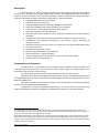
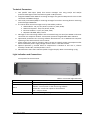
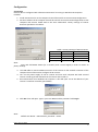
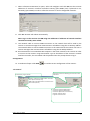
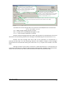
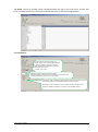
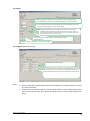
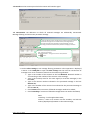
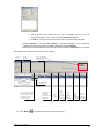
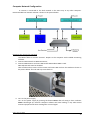
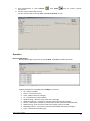
IP RECEIVER RL10 User Manual UAB Trikdis Draugystes g. 17 Kaunas, LT-51229 E-mail: [email protected] http://www.trikdis.lt The purpose of the document This document describes the features, operation and configuration of IP receiver RL10. Contents Description.................................................................................................................................. 3 Composition and Operation ....................................................................................................... 3 Technical Parameters ................................................................................................................. 4 Light Indication and Connections ............................................................................................... 4 Equipment .................................................................................................................................. 5 Configuration .............................................................................................................................. 6 Connection.............................................................................................................................. 6 Configuration .......................................................................................................................... 7 Computer Network Configuration ............................................................................................ 13 Operation.................................................................................................................................. 14 Receiving Messages .............................................................................................................. 14 Remote Programming of Transmission Modules ................................................................. 15 Remote Control of Transmission Devices ............................................................................. 17 Receiver’s Internal Event Messages ......................................................................................... 18 Annex 1. Operation of Concentrator Filter .............................................................................. 21 Annex 2. Data Output message format .................................................................................... 23 RL10v3_UM_EN_150901 2 Description IP receiver RL10 is an alarm message receiver for monitoring stations. RL10 receives burglary and fire alarm messages sent by UAB Trikdis communicators via GSM/GPRS/Internet networks. It transmits received messages to the monitoring software. Receiver automatically tracks connection with every registered message transmitter (communicator1). Receiver features: integrated industrial Linux OS computer; 2 network interface controllers; integrated GSM modem for receiving messages in SMS format; connection to SMPP server of the network service provider; 2 serial ports for receiving messages from other devices; automatic registration of communicators; automatic connection control of every registered communicator using individual schedules; message transmission to the monitoring software using either serial port or LAN; configuration and operation monitoring of the receiver using a Windows OS computer via LAN; multi-site connectivity to the receiver via LAN. Every user is granted individual access to receiver functions; message filtering and conversion; export of registered objects’ list to CSV file; search function for a registered object; remote configuration of communicators, and remote firmware update; remote control of communicators. Composition and Operation IP receiver RL10 – is a Linux OS industrial computer with 2 network interface controllers and a software IPcom mounted into a 19“ 2U enclosure with a power supply unit. GSM modem is also mounted into the enclosure of the receiver. IP receiver RL10 can be connected to two computer networks: LAN1 ir LAN2. Software IPcom receives messages from objects’ alarm systems via WAN1 and WAN2 ports and GSM modem of the receiver. It transmits received messages to the monitoring software via serial Output and WAN ports. Messages received via serial ports In1 and In2 are retransmitted to the monitoring software unprocessed via serial Output and WAN ports. Configuration, control and operation monitoring of IP receiver RL10 is performed using software IPcomControl 3 which is installed into a Windows OS computer in the same network. 1 Communicator – is a part of a protected object burglary or fire alarm system that supports a continuous connection with the control panel and continually communicates with the monitoring station receiver. After an event, receiver transmits an encrypted event message. UAB Trikdis manufactures communicators for receiving signals (messages) from various manufacturers control panels and communicating with monitoring station receiver RL10 via GPRS, SMS or other internet connection channels. It also manufactures control panels whose communicators communicate with receiver RL10 via GPRS or SMS connection channels. RL10v3_UM_EN_150901 3 Technical Parameters 1. Two parallel LAN inputs (RJ45) that receive messages sent using TCP/IP and UDP/IP protocols. Messages will be received encrypted in TRK protocols. 2. Integrated GSM modem GM5 for receiving messages encrypted in TRK protocols sent via CSD connection and SMS messages. 3. Two serial ports RS232 (DB9) for receiving messages from other receiving devices. Receiving protocol Surgard MLR2-DG. 4. IP receiver RL10 receives messages sent by UAB Trikdis products: GSM modules - G5, G7, G10, G10T v1, G10T v2, G10C, G10D; GSM control panels - CG2, CG3, SP131, SP133; Ethernet modules - E2, E7, E10, E10T, E10C; Repeaters RR-GSM, RR-IP, R-IP12 5. Messages to the monitoring software are transmitted using one serial port RS232 or Etherner connection via computer network. Transmission protocols Surgard MLR2-DG or Monas3. 6. Operational parameters are set using software IPcomControl 3 on a Windows OS computer operating in the same network as the receiver. 7. Power supply from 50±1 Hz frequency 230 V current AC network. Power consumption under 60 W. Permissible power supply voltage variation limits - from 100 to 240 V. 8. Optimal operation is ensured when air temperature is between 0 and +55 °C, relative humidity is under 90%, and temperature +20 °C. 9. Measurements 450 x 100 x 320 mm (width x height x depth). Mass not exceeding 4,5 kg. Light Indication and Connections Front panel of IP receiver RL10. Indicator Power Status Event Table 1. Front Panel Light Indication Description green ON - power supply is on green ON – output to monitoring software is connected red ON – no connection to the monitoring software yellow ON – one fo the outputs is disconnected OFF – output is down blue ON – message is being transmitted to the output RL10v3_UM_EN_150901 4 Rear panel of IP receiver RL10. Table 2. Rear Panel Connectors Connection WAN1 WAN2 In1 In2 Output Reset Antenna AC input CF PS/2 VGA USB Description 1st Ethernet port 2nd Ethernet port Serial port RS232 for connecting other receiving devices Serial port RS232 for connecting other receiving devices Serial port RS232 for output to the monitoring software Reset button to restore to factory settings Connector for GSM receiver antenna Power supply connection and ON/OFF button Grounding terminal Cap covered memory drive with OS connected to the socket Keyboard connector VGA connector for monitor For manufacturer needs Equipment IP receiver RL10 - 1 pc.; Power supply cable (1.5 m) - 1 pc.; RS232 cable (1.8 m) - 1 pc.; LAN cable - 1 pc.; GSM antenna - 1 pc.; CD containing this User Manual and software IPcomControl 3 for setting parameters - 1 pc. RL10v3_UM_EN_150901 5 Configuration Connection Receiver RL10 is configured with software IPcomControl 3 running on Windows OS computer installed. 1. Install IPcomControl 3 on the computer that will be used for IP receiver RL10 configuration. 2. Set the IP address of the computer that will be used for IP receiver RL10 configuration so that computer and receiver would work in the same subnetwork. Factory settings of receiver RL10 are specified in the Table 3. Table 3. Factory Settings of Receiver RL10 WAN1 WAN2 IP address 192.168.0.2 192.168.100.3 Port 55000 55000 Subnet Mask 255.255.255.0 255.255.255.0 Gateway 192.168.0.254 19168.100.254 Note: Press and hold RESET button for 5 seconds (until a sound signal) in order to restore to factory settings. 3. Use LAN cable to connect WAN2 connector of the receiver to the network connector of the computer that will be used to configure the IP receiver. 4. Turn on the power supply of the IP receiver and wait until computer OS loads. Second receiver sound signal will indicate that the receiver has turned on. 5. Run IPcomControl 3 on Windows OS computer. A box will open. Put in the address of your receiver‘s interface controller (port WAN2). 6. Click OK. A box will open. Type in your User Name and the password. Click Login. Note: Default User Name – administrator, password – admin. RL10v3_UM_EN_150901 6 7. When software IPcomControl 3 opens, select tab Configure and click Get. Set the internet addresses of receiver‘s interface controllers Primary (port WAN1) and, if planned to use, Secondary (port WAN2) in order to allow the receiver to work in designated networks. 8. Click Set. Receiver will reboot automatically. Note. Log in to the receiver via LAN using new addresses if addresses of network interface controller Secondary were edited. 9. Use network cable to connect WAN1 connector to the network that will be used by the receiver to receive messages that communicators will address using the set Primary address. Use network cable to connect WAN2 connector to the network that the receiver will use to receive messages that communicators will address using the set Backup address. 10. Run IPcomControl 3 on a Windows OS computer in the same network as the receiver in order to connect to the receiver using LAN network. Type in the address of the receiver‘s network interface controller, the User Name and the password into the prompt boxes to log in. Configuration 11. A window will open. Click Read to read the current configuration of the receiver. Tab General. Automatic and manual rebooting of the receiver. Event code R 313. IPcomControl program version Receiver‘s software and GSM modem connection status (Event codes E/R 753); GSM modem and GSM network connection status (Event codes E/R 751). - Number of registered GPRS objects; Number of registered SMS objects; Number of objects with lost connection; Message reception speed; Program version of IPcom. RL10v3_UM_EN_150901 7 Message with event code E 762 (GPRS conncetion to communicator is lost) formation parameters: Multiplier – number of PING messages not received by the communicator in IP protocols in a row, NPING Tolerance – time correction, TTolerance Message with event code E 752 (GSM connection to communicator is lost) formation parameters: Multiplier – number of PING messages not transmitted by the communicator in SMS format in a row, NPING Tolerance – time correction, TTolerance Number of received PING or other messages after which a restoration of connection to communicator message will be formed, NPING (R 762 – GPRS, o R 752 – GSM). Number of the receiver and its line Formation time of the message about lost connection with GPRS/Ethernet communicator: Tmessage= TPING x NPING + TTolerance TPING – PING message sending period in seconds. NPING – number of not received PING messages in a row. TTolerance – time correction coefficient in seconds. Receiver will form message with event code E 762 (connection to communicator is lost) and will send it to the monitoring software if no message is received during the set control time Tmessage. Receiver will form message with event code R 762 (connection to communicator is restored) and will send it to the monitoring software if the number of PING or other messages received from the communicator during the control time Tmessage is equal to the number in the box GPRS. Message formation times (when connection to SMS communicators is lost/restored) are calculated in the same way. However, PING message sending periods via SMS by the communicator are put into the formulas, and values of N and Tolerance are taken from the boxes GSM. RL10v3_UM_EN_150901 8 Tab Events. The list of possible events is displayed under this tab. In case of an event, receiver will form a message with the list code Event code and will send it to the monitoring software. Tab Connections. Program IPcom message receiving port numbers. Object alarm communicator messages in TCP/IP or UDP/IP protocols from external networks (that get into LAN network) must be forwarded to these ports. Started – port is open. Message decryption password (default 123456). Message encryption password set in communicator has to be the same as message decryption password set in the receiver. If the option Trikdis is selected, integrated GSM modem will be enabled and the receiver will be able to receive SMS messages from communicators. SMPP option must be selected for receiving SMS messages via SMPP service. Connection to SMPP parameters must be set in the tab SMPP receivers. RL10v3_UM_EN_150901 9 Tab Output. Monitoring program IP addresses. Put in the values and select Started when data exchange between the receiver and the monitoring program is carried out via LAN. Set data exchange speed and select Started when data exchange between the receiver and the monitoring program is carrid out via port RS232. Message E 704 (connection to multiple communicators is lost) formation parameters. Message will be formed when connection to the set number of communicators is lost in a specified amount of time, for example, connection with 10 communicators is lost in 1 second. Interval of conection control message sent to monitoring program. Messages E/R 713 Protocol for message transmission to the monitoring program Tab Configure (Network settings). LAN1 and LAN2 network settings. IP address of remote server to which control signal PING will be sent with set periodicity. In this case the receiver will be able to examine the quality of message transmission via LAN1 and LAN2. Event codes E/R 732. Notes: 1. Receiver will reboot automatically when internet addresses are edited and Set is clicked on. Event code R 313. 2. Prepare the local network (LAN) in a way that information in TCP or UDP protocols from open internet would reach ports WAN1 and WAN2 of the receiver RL10 (forward the ports). RL10v3_UM_EN_150901 10 Tab Sounds. Set the events upon which the receiver will sound a signal. Tab Concentrator. Set addresses to which all received messages are additionally transmitted. Message filtering and conversion parameter settings. Server IP address and port number of the monitoring program to which all received messages are transmitted without processing. Receiver transmits messages when [Started] is checked. Messages are sent according Contact ID code table when [Standard messages] is checked. Activation of serial ports In1 and In2. Edit – edit port parameters. Activate/Deactivate – change port status to active/inactive. Click to save. Use box Filter settings to set message filtering parameters. Filter operation is displayed in Annex 1. Click Add filter to open tab Filter settings. Set the rules for transmission of messages sent via IP connection channels to the monitoring software: Type in the number of the network in the field Network. Network number is set according to the number of the receiver in the message; Type in the inactivity time for the same signal (or recurrent messages) in the box Time; Type in the receiver number indicated in the processed message in the box Receiver no; Type in the number of the receiver line indicated in the processed message in the box Line no; Check Convert if the structure of filtered messages needs to be edited; Check Tunneling if structure of filtered messages does not need to be edited; Note: Tunneling – let through without edits; Convert – write in set receiver and line numbers, and edit the order of displayed information in the radio message; RL10v3_UM_EN_150901 11 Type in special event codes that are used in RAS-2M system to turn off repeated messages in the system in the field Events one per line. Click OK to save new values. Several new filters can be formed and used. Check Tunneling in the field Not filtered to transmit message to the monitoring software using receiver and line numbers indicated in the tab General. Messages are transmitted using set receiver and line numbers if Tunneling is unchecked. Tab Users. Create program users and set access rights. User login name Access to summarised information about connection with communicators User login password User is forbidden to access to the function User is provided with Read-only access to the function User is provided with full access to the function Access to setting up of receiver parameters (to tabs General, Events, Connections, Output, Configure Time, Sounds, Concentrator, Users) 12. Click Write Access to remote setting up of parameters for control panels and communicators Access to remote changing of PGM status for Access to control panels tabs Data and and Objects communicators Access to remote bypassing of control panels’ zones Access to remote ARMing/ DISARMing of control panels Access to remote resetting of fire detectors to save the edits into the receiver memory. RL10v3_UM_EN_150901 12 Computer Network Configuration IP receiver is connected to the local network in the same way as any other computer. Recommended local network scheme is shown in the picture below. Preparing the receiver for operation 1. Connect Output. Use RS232 cable to connect receiver’s Output to the computer with installed monitoring software. 2. Connect LAN networks to WAN connectors. 3. Connect GSM antenna and insert SIM card if GSM modem GM5 is used. SIM card PIN code must be disabled. Take off side and top covers of the receiver and insert SIM card into the modem as shown in the picture below. Put side and top covers back on. 4. Turn on the power supply. Turn on the power supply by pressing the button Power after all wiring is done. Indicator Power should light up. Receiver computer software will start loading. It may take several minutes. Equipment will start working after a sound signal. RL10v3_UM_EN_150901 13 5. Run IPcomControl 3. Click Connect , then Read and set current receiver parameters. 6. Set the current time of the receiver. Set the receiver clock in the tab Time. Click Set to PC time to save. Operation Receiving Messages Received messages can be seen in the tab Data. Click Clear to delete all entries. Registered object list is displayed in tab Object. It contains: ID – object’s number; Status – connection status; Level - GSM connection strength; IP – transmission module address; GPRS last ping – date ant time of the last IP message; GPRS ping interval – connection control period of IP channel messages; Phone – subscription number of transmission module (communicator) SIM card; GSM last ping – date and time of the last message received via GSM; GSM ping interval – connection control period of GSM connection messages; Type – transmission module type; RL10v3_UM_EN_150901 14 Device version – transmission module program version; IMEI/MAC – transmission module IMEI or MAC number. Use function Search to quickly find the data row for required object burglary or fire alarm communicator; function Remove object – to delete a selected line from the list; function Refresh list every: ...... seconds – to set list update period; click Export to CSV file – to create a list of registered objects (communicators) in a CSV file that can be opened using, for example, MS Office program Excel. Remote Programming of Transmission Modules Settings of the object transmission module can be set remotely. a) setting up parameters for one transmission module Right-click on the selected transmission module to open the menu and open the program to set the parameters. Log in, read current parameters and set them the according to the transmission module user manual. Save into the module memory. Note: Logging in, reading and saving might take several minutes. Program will indicate when the next action is available. Log off when finished. Module will reboot and will automatically resume reporting to the receiver after a certain time period. b) setting up parameters of multiple modules at once Right-click on any security module to open the menu and select Configure multiple modules. RL10v3_UM_EN_150901 15 A new window will open. Specify the sequence of transmission modules to be reprogrammed and put in the new parameters in the tab Data fields. Specify the sequence (from...to) of transmission modules undergoing the edit of parameters in the section Select objects. Click Get object list to open the list of all modules within the specified limits on the right side. Serial module numbers, IP addresses, module types and their program versions will be indicated in the list. If transmission modules of different types are displayed, deselect to eliminate from the list. Sequence of module numbers to be reprogrammed Primary channel parameters: Check the box and put in the data Backup channel parameters: Check the box and put in the data List of objects to be reprogrammed Module log in passwords Network log in parameters: Check the box and put in the data PING period of connection control signals Indicate only those parameters that will be edited in sections Primary reporting and Backup reporting. Specify APN, User, Password and DNS data if parameters of connection to the network operator will be edited. Select Repeat operation for failed module and specify the period value if connection control period is to be edited. Click Start programming to start a process of parameters edit. It may take several minutes. Program will inform once the process is finished. Click Stop to terminate the process. c) upgrading firmware for multiple modules Right-click and select Configure multiple modules to program multiple modules. A new window opens. Specify the sequence of modules to be repgrogrammed and program versions in the tab Data fields. RL10v3_UM_EN_150901 16 Sequence of module numbers to be reprogrammed List of objects to be reprogrammed Sequence of firmware versions of objects to be reprogrammed: Check the box and put in the data Module log in passwords Location of the last firmware version Check Program modules with firmwares and type in the sequence of program versions. Click Select firmware file and locate the file with extension *.prg. Click Start programming to start the process of parameters edit. It may take several minutes. Click Stop to terminate the process. Program versions of the modules are displayed in the tab Objects once process is finished. Remote Control of Transmission Devices Transmission module in the object can be controlled remotely. It is important for the transmission module to support this function (not all manufactured transmission modules supports it). Right-click on the selected transmission module to open the menu and select Remote control. A new window will open. Indicate the actions you would like to take and click Write zone and Write output at the bottom of the window. Click Refresh to refresh the window and check the edits. RL10v3_UM_EN_150901 17 Click X (Close) to close the window once finished. Receiver’s Internal Event Messages There is receiver RL10’th internal event code list in the table below. Please find conditions for generating of Internal Event Messages and sending them to the monitoring software in the same table below. Internal Event Message string values Event Code C ID Editing Allowed Name Event message will be generated if: Receiver Line No No Account No (Object ID) Event Code Partition No Zone No E762 Pre-set Pre-set GPRS Receiver Receiver’s connection lost No Line No Object ID transferred by Tx Module R762 GPRS connection restored Object ID transferred by Tx Module E752 R752 Pre-set Pre-set Receiver Receiver’s No Line No GSM connection lost GSM connection restored Object’s Tx Module operates in GPRS mode; No any signal out of Tx Module within pre-set check time; Type of Tx Module is known; Switched on receiving via GSM modem/SMPP; At least one SMS message has been received from Tx Module; Massive GPRS connection loss has not been detected; Object’s Tx Module operates in GSM mode; Pre-set number of messages has been received to define GPRS connection restoration; Massive GPRS connection restoration has not been detected; - - N/A - - N/A RL10v3_UM_EN_150901 18 E704 R764 Massive Communication loss Massive GPRS communication restore R754 Massive GSM restore E732 WAN ping timeout Pre-set Receiver No Pre-set Receiver No Pre-set Receiver No Pre-set Receiver No Pre-set Receiver’s Line No Pre-set Receiver’s Line No Pre-set Receiver’s Line No Pre-set Receiver’s Line No 0000 hard coded (000) Pre-set number of either GPRS or GSM connection losses per second has been detected 0000 hard coded (000) Pre-set number of GPRS connection restorations per second has been detected; 0000 hard coded (000) Pre-set number of GSM connection restorations per second has been detected; 0000 hard coded (ETH No) 3 times in turn there is no answer signal from “PING“ addressee (Object’s Tx Module); R732 WAN ping restored Pre-set Pre-set Receiver Receiver’s No Line No 0000 hard coded Connection loss with particular Ethernet controller has been detected; (ETH No) There is at least one answer signal received from “PING“ addressee (Object’s Tx Module); E753 Pre-set Pre-set GSM modem no Receiver Receiver’s response No Line No 0000 hard coded (000) R753 GSM modem responded Pre-set Pre-set Receiver Receiver’s No Line No 0000 hard coded (000) E751 Pre-set Pre-set GSM connection Receiver Receiver’s is offline No Line No 0000 hard coded (000) 0000 hard coded (000) 0000 hard coded (ETH No) 0000 hard coded NET cable plugging out has been detected; (ETH No) NET cable has been plugged into particular Ethernet controller; 0000 hard coded (COM No) 0000 hard coded (COM No) R751 E733 R733 E713 R713 Pre-set GSM connection Receiver is online No Pre-set WAN cable Receiver disconnected No Pre-set WAN cable Receiver connected No Pre-set (COM) Receiver Receiver no heart beat No (COM) Receiver Pre-set heart beat Receiver restored No Pre-set Receiver’s Line No Pre-set Receiver’s Line No Pre-set Receiver’s Line No Pre-set Receiver’s Line No Pre-set Receiver’s Line No R313 System rebooted Pre-set Pre-set Receiver Receiver’s No Line No 0000 hard coded (000) R305 System started Pre-set Pre-set Receiver Receiver’s No Line No 0000 hard coded (000) GSM modem answer signal has not been received within 10 seconds; Connection loss with GSM modem has been detected; At least one message has been received from GSM modem; GSM modem notifies with service message that it’s lost GSM connection; At least 1 minute has gone past from system start; GSM connection loss has been detected; GSM modem notifies with service message that it has restored GSM connection; NET cable has been plugged out of particular Ethernet controller; No signal has been received per minute via COM input; COM input loss has been detected; At least one signal or message has been received via COM input; Reboot command created by IPcomControl has been received; H/W fail occurred while signals via COM input were received; IPCom has started; Object’s Tx Module operates in GPRS mode; A Message has been received via GSM; R755 GSM device mode Pre-set Pre-set Receiver Receiver’s No Line No Object ID transferred by Tx Module Object’s Tx Module operates in GSM mode; The FIRST message has been received via GSM; Connection loss with Tx Module has been detected; Pre-set number of messages has been received via GSM to define GSM connection restoration; RL10v3_UM_EN_150901 19 E350 R350 Connection trouble Connection restore Pre-set Pre-set Receiver Receiver’s No Line No Pre-set Pre-set Receiver Receiver’s No Line No Object ID transferred by Tx Module Object ID transferred by Tx Module Object’s Tx Module operates in GPRS mode; Massive GPRS connection loss has not been detected; Either Tx Module is unable to transfer messages via GSM or no messages has been received out of Tx Module via GSM; No messages out of Tx Module within pre-set check time; Object’s Tx Module operates in GSM mode; No messages out of Tx Module within pre-set check time; Massive GSM connection loss has not been detected; Connection loss with Object’s Tx Module has been detected; Massive GPRS connection restoration has not been detected; Pre-set number of messages has been received via GPRS to define GPRS connection restoration; Connection loss with Object’s Tx Module has been detected; Massive GSM connection restoration has not been detected; Pre-set number of messages has been received via GSM to define GSM connection restoration; RL10v3_UM_EN_150901 20 Annex 1. Operation of Concentrator Filter Algorithm of concentrator filtering RL10v3_UM_EN_150901 21 Example of radio message (encrypted in RAS-2M) filtering RL10v3_UM_EN_150901 22 Annex 2. Data Output message format Output message format: 50RLs18AAAAEEEEPPZZZT 50 R L s 18 AAAA EEEE PP ZZZ T =Basic protocol =Receiver Number =Line Number =space =the token used to identify the message as Contact ID =Account Number (Object ID) =Event code =Partition Number =Zone Number =Terminator (DC4) True message example: 5021 180000E71399001<DC4> RL10v3_UM_EN_150901 23