1
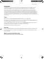
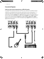
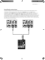
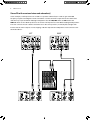
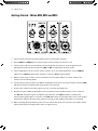
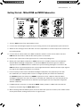
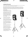
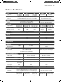
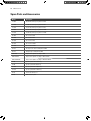
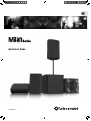
Series
Quickstart Guide
A54-00000-85132
2
Milan Series
Important Safety
Instructions
Terminals marked with this
symbol carry electrical
current of sufficient
magnitude to constitute risk of electric
shock. Use only high-quality
commercially-available speaker cables
with plugs pre-installed. All other
installation or modification should be
performed only by qualified personnel.
This symbol, wherever it
appears, alerts you to the
presence of uninsulated
dangerous voltage inside the
enclosure - voltage that may be
sufficient to constitute a risk of shock.
This symbol, wherever it
appears, alerts you to
important operating and
maintenance instructions in the
accompanying literature. Please read
the manual.
Caution
To reduce the risk of electric
shock, do not remove
the top cover (or the rear section).
No user serviceable parts inside.
Refer servicing to qualified personnel.
Caution
To reduce the risk of fire
or electric shock, do not
expose this appliance to rain and
moisture. The apparatus shall not
be exposed to dripping or splashing
liquids and no objects filled with
liquids, such as vases, shall be placed
on the apparatus.
Caution
These service instructions
are for use by qualified
service personnel only. To reduce the
risk of electric shock do not perform
any servicing other than that contained
in the operation instructions. Repairs
have to be performed by qualified
service personnel.
1. Read these instructions.
2. Keep these instructions.
3. Heed all warnings.
4. Follow all instructions.
5. Do not use this apparatus
near water.
6. Clean only with dry cloth.
LEGAL DISCLAIMER
7. Do not block any ventilation
openings. Install in accordance with
the manufacturer’s instructions.
TECHNICAL SPECIFICATIONS AND
APPEARANCES ARE SUBJECT TO
CHANGE WITHOUT NOTICE AND
ACCURACY IS NOT GUARANTEED.
BEHRINGER, KLARK TEKNIK, MIDAS,
BUGERA, AND TURBOSOUND
ARE PART OF THE MUSIC GROUP
(MUSIC-GROUP.COM).
ALL TRADEMARKS ARE THE
PROPERTY OF THEIR RESPECTIVE
OWNERS. MUSIC GROUP ACCEPTS
NO LIABILITY FOR ANY LOSS
WHICH MAY BE SUFFERED BY
ANY PERSON WHO RELIES EITHER
WHOLLY OR IN PART UPON ANY
DESCRIPTION, PHOTOGRAPH OR
STATEMENT CONTAINED HEREIN.
COLORS AND SPECIFICATIONS MAY
VARY FROM ACTUAL PRODUCT.
MUSIC GROUP PRODUCTS ARE
SOLD THROUGH AUTHORIZED
FULLFILLERS AND RESELLERS ONLY.
FULLFILLERS AND RESELLERS ARE
NOT AGENTS OF MUSIC GROUP
AND HAVE ABSOLUTELY NO
AUTHORITY TO BIND MUSIC GROUP
BY ANY EXPRESS OR IMPLIED
UNDERTAKING OR REPRESENTATION.
THIS MANUAL IS COPYRIGHTED.
NO PART OF THIS MANUAL MAY BE
REPRODUCED OR TRANSMITTED
IN ANY FORM OR BY ANY MEANS,
ELECTRONIC OR MECHANICAL,
INCLUDING PHOTOCOPYING
AND RECORDING OF ANY KIND,
FOR ANY PURPOSE, WITHOUT THE
EXPRESS WRITTEN PERMISSION OF
MUSIC GROUP IP LTD.
8. Do not install near any
heat sources such as radiators,
heat registers, stoves, or other
apparatus (including amplifiers)
that produce heat.
9. Do not defeat the safety purpose of
the polarized or grounding-type plug.
A polarized plug has two blades with
one wider than the other. A groundingtype plug has two blades and a third
grounding prong. The wide blade or
the third prong are provided for your
safety. If the provided plug does not fit
into your outlet, consult an electrician
for replacement of the obsolete outlet.
10. Protect the power cord from being
walked on or pinched particularly
at plugs, convenience receptacles,
and the point where they exit from
the apparatus.
11. Use only attachments/accessories
specified by the manufacturer.
12. Use only
with the cart,
stand, tripod,
bracket, or table
specified by the
manufacturer,
or sold with
the apparatus.
When a cart is used, use caution when
moving the cart/apparatus combination
to avoid injury from tip-over.
13. Unplug this apparatus during
lightning storms or when unused
for long periods of time.
14. Refer all servicing to qualified
service personnel. Servicing is required
when the apparatus has been damaged
in any way, such as power supply cord
or plug is damaged, liquid has been
spilled or objects have fallen into the
apparatus, the apparatus has been
exposed to rain or moisture, does not
operate normally, or has been dropped.
15. The apparatus shall be connected
to a MAINS socket outlet with a
protective earthing connection.
16. Where the MAINS
plug or an appliance
coupler is used as the
disconnect device,
the disconnect
device shall remain
readily operable.
ALL RIGHTS RESERVED.
© 2013 MUSIC Group IP Ltd.
Trident Chambers, Wickhams Cay,
P.O. Box 146, Road Town, Tortola,
British Virgin Islands
LIMITED WARRANTY
For the applicable warranty
terms and conditions and
additional information regarding
MUSIC Group’s Limited Warranty,
please see complete details online at
www.music-group.com/warranty.
Quickstart Guide
Introduction
Congratulations, you have purchased a professional loudspeaker product from the Milan series of
loudspeakers, designed to give you the best in audio quality and many years of reliable, troublefree operation. It offers excellent pattern control, superior audio quality, proven reliability, ease of
setup, consistent performance, and the backing of a world leader in acoustics technology including a
comprehensive warranty against manufacturing defects. Please read through this guide carefully before
you attempt to operate the loudspeaker system. It contains valuable information which will enable you
to quickly and easily connect the loudspeakers to your outboard equipment; and important system and
set-up checks.
Thanks
Thank you for choosing a TURBOSOUND loudspeaker product for your application.
By engaging in an on-going rigorous program of research and development all TURBOSOUND products
are carefully engineered for world class performance and reliability.
If you would like further information about this or any other TURBOSOUND product, please contact us.
Detailed product information is available on our website at: turbosound.com
We look forward to helping you in the near future.
Unpacking
After unpacking the unit please check carefully for damage. If damage is found, please notify the carrier
concerned at once. You, the consignee, must instigate any claim. Please retain all packaging in case of
future re-shipment.
Models covered by this Quick Start Guide
Milan M10, Milan M12, Milan M15, Milan M15B, Milan M18B
3
4
Milan Series
Connection Diagrams
Small duo setup using the integrated mixer and Mix Out function
The integrated two channel mixer allows the simultaneous use of either two low impedance dynamic
microphones, a microphone and a line level source, or two line level sources. The line level source(s)
can be an acoustic instrument such as a guitar with either passive or active on-board electrics,
a keyboard, or MP3 player. Connect dynamic microphones directly to either of the combo jack/XLR
input connectors, switch the MIC/LINE switch to MIC and adjust the volume level as desired. Connect line
sources to either of the combo jack/XLR connectors, switch the MIC/LINE switch to LINE and adjust the
volume control as desired. Switch the LOW CUT filter to 'OFF' and switch the PROG switch to 'MUSIC'.
Additional microphones and sources can be connected by using the MIX OUT function to daisy-chain to
additional Milan loudspeakers.
Quickstart Guide
5
Stereo PA with an external mixer
Two Milan loudspeakers form the left and right elements of a stereo PA setup with all signal sources
connected to an external mixing console. Ensure that the MIC/LINE switch is set to LINE on both
loudspeakers. Set the LOW CUT switch to the ‘OFF’ position when not using subwoofers. For mixed vocal
and music program material set the PROG switch to 'MUSIC'. Bring up the master faders on the mixer,
ensuring that the outputs are not clipping, and then adjust both loudspeakers’ level controls to the desired
loudness. Adjust the bass and treble controls as required to acheive a suitable frequency response from
the system. For consistent balance and response set the level controls and tone controls to approximately
the same positions on both cabinets.
6
Milan Series
Stereo PA with an external mixer and subwoofer(s)
In this example, sub frequencies are routed to a separate subwoofer(s) in order to gain extended
frequency response and higher overall sound level. Connect the mixer output first to the subwoofers
and then loop up to the Milan mid/high loudspeakers. Set the MIC/LINE switch to LINE and set the
LOW CUT switch to the 100 Hz position to roll off the low frequencies to the Milan mid/high loudspeakers.
The tone controls on both cabinets should be set to the same positions, nominally flat to begin with.
Ensure that the mixer outputs are not clipping, and then adjust both loudspeakers’ level controls to the
desired loudness.
LEFT
LEFT
RIGHT
RIGHT
Quickstart Guide
Stereo PA with powered wedge monitors
On larger gigs a separate monitor system provides good quality foldback for individual performers and
helps to keep the front of house PA sound less cluttered. Set the LOW CUT switch on the monitor speakers
to the 100 Hz position for best results if used on the floor.
LEFT
LEFT
RIGHT
RIGHT
MON1
MON1
MON2
MON2
7
8
Milan Series
Connecting to the Milan Loudspeaker
1. Mains Connector and Fuseholder
Mains power is connected to the loudspeaker
via a combination IEC connector and fuseholder.
2. Mains Switch
Rocker switch turns mains power on to the
10
11
12
13
13
14
9
14
loudspeaker. Make sure the level controls are
fully off (MIN) before switching on.
3. Signal Input
These combo female XLR/jack connectors
8
7
accept both XLR connectors and mono
(2 pole) or stereo (3 pole) ¼" jack plugs for use
with a variety of balanced and unbalanced
6
microphones, instruments and line sources.
5
4
3
3
The inputs are electronically balanced to avoid
hum loops and RF interference, and are wired
pin 2 hot, pin 3 cold.
100 Hz Low Cut Switch
This low cut filter can be switched in when
using the Milan loudspeaker with subwoofers
or when used as a floor monitor. It introduces
a fourth order low cut filter in the lower part of
1
2
the frequency response at 100 Hz, and is useful
to avoid boominess due to proximity to the
floor when the loudspeaker is used as a floor
monitor. The low cut should also be selected
when used with sub-bass loudspeakers
and allows bass frequencies to be routed
appropriately to the sub-bass speakers,
avoiding an overlap, and giving greater clarity and definition to the overall sound.
4. Mix Out
A balanced line level signal output on a balanced male XLR connector that connects to additional
powered Milan loudspeakers. This output contains a mix of all connected sources and is post-EQ,
although it is independent of the 100 Hz low cut switch. Note that adjusting equalisation will
similarly affect any additional Milan loudspeakers connected to this output.
5. Program Switch
Sets a frequency response contour optimised for either voices or mixed music program material.
6. Treble Control
The treble control provides ±6 dB of shelving at 12 kHz. Always use equalisation sparingly, aiming to
cut rather than boost especially when the loudspeaker is used near boundaries such as walls or floors.
Quickstart Guide
9
7. Bass Control
The bass control provides ±6 dB of shelving at 80 Hz. Always use equalisation sparingly,
aiming to cut rather than boost especially when the loudspeaker is used near boundaries such as
walls or floors.
8. Power On Indicator
Blue LED illuminates when mains power is applied to the loudspeaker and powered up via the
rocker switch.
9. Signal Indicator
Illuminates green when the signal level reaches -6 dB, and is a useful indicator of the input signal
approaching the limiter threshold.
10. Limit Indicator
Illuminates red when the signal level approaches maximum and the limiters start working.
Frequent and/or continuous lighting of limit LED indicates overdriving. If this occurs reduce the
input level to the loudspeaker or enlarge your system with additional loudspeakers.
11. Front LED Status
The function of the illuminated front badge can be toggled between permanently on,
permanently off, or to indicate action of the limiting circuits.
12. Mic / Line Switch
Selects the input for that channel to accept either a low level, low impedance microphone,
or a high level, high impedance source such as a mixing console, keyboard or acoustic
instrument with onboard electrics. The mic input is not suitable for condenser microphones that
require phantom power.
13. Level Control
Rotary level control which attenuates the input signal level of the connected instrument /
line source for that input channel. The range (mic) is from -∞ (MIN) to +68 dB (MAX) and (line) from
-∞ (MIN) to +38 dB (MAX).
10
Milan Series
Connecting to the Milan Subwoofer
8
7
6
5
5
9
4
10
4
11
12
1
2
3
1. Mains Connector
Mains power is connected to the subwoofer via an IEC connector.
2. Fuseholder
Replace fuse only with the same type and rating.
3. Mains Switch
Toggle push switch turns mains power on to the loudspeaker. Make sure the level control is fully
off (MIN) before switching on.
4. Inputs
These combo female XLR/jack connectors accept both 3-pin XLR connectors and mono (2 pole)
or stereo (3 pole) ¼" jack plugs for connection to balanced or unbalanced mixing console outputs.
The inputs are electronically balanced to avoid hum loops and RF interference, and are wired
pin 2 hot, pin 3 cold.
Quickstart Guide
11
5. Thru Connections
These 3-pin balanced male XLR connectors provide independent full range audio signals from
each input channel for loop-through connections to Milan two-way loudspeakers or additional
Milan subwoofers.
6. Boost
Applies +3 dB of boost with a Q factor of 1 at a centre frequency selected via the associated boost
freq control (12).
7. Limit Indicator
Illuminates red when the signal level approaches maximum and the limiters start working.
Frequent and/or continuous lighting of limit LED indicates overdriving. If this occurs reduce the
input level to the loudspeaker or enlarge your system with additional loudspeakers.
8. Signal Indicator
Illuminates green when the signal level reaches -6 dB, and is a useful indicator of the input signal
approaching the limiter threshold.
9. Power On Indicator
Blue LED illuminates when mains power is applied to the subwoofer and powered up via the
rocker switch.
10. Polarity
Reverses the polarity of the subwoofer relative to the two-way Milan loudspeakers connected to
the thru outputs.
11. Level Control
Rotary level control which attenuates the input signal level of the subwoofer and (line) from
-∞ (MIN) to +43 dB (MAX).
12. Boost Freq
Selects the centre frequency at which the boost is applied, and is continuously variable from
40 Hz to 90 Hz.
12
Milan Series
Getting Started – Milan M10, M12 and M15
1. Turn the level controls fully anticlockwise (zero) on both input channels.
2. Set the BASS and TREBLE tone controls to their centre position (no boost or cut).
3. Connect your signal sources (mixing console, keyboard, microphone, acoustic guitar) to the
appropriate input connectors and select MIC or LINE as appropriate for that source.
4. If the loudspeaker is to be used as a floor monitor, or for use with subwoofers, set the LOW CUT
switch to the '100 HZ' position (up); otherwise select the 'OFF' position (down).
5. Switch on the mixer or other source and make sure the output faders or master output level
controls are turned fully down.
6. Connect the AC mains cable to the Milan loudspeaker and turn on the mains switch. The blue PWR
LED will illuminate to indicate that mains power is connected.
7. Increase the output level of the signal source to a normal operating level.
8. Slowly turn up the Milan loudspeaker’s level control(s) until a suitable volume level is reached.
The SIG LED illuminates green to indicate signal present. The LIM LED flashes red when the
system limiting although it is normal for the LIM LED to flash occasionally. Excessive or prolonged
illumination indicates that the input signal is too high or that additional speakers are required.
9. When shutting down the Milan system, first turn down the input level controls, then switch off the
mains power before turning off the mixer or signal source.
Quickstart Guide
13
Getting Started – Milan M15B and M18B Subwoofers
1. Turn the LEVEL control fully anticlockwise (zero).
2. Connect the left and right outputs from your mixing console to the appropriate input connectors.
3. Switch on the mixing console and make sure the output faders or master output level controls are
turned fully down.
4. Connect the AC mains cable to the Milan subwoofer and turn on the mains switch. The blue
PWR LED will illuminate to indicate that mains power is connected.
5. Increase the output level of the signal source to a normal operating level.
6. Slowly turn up the Milan subwoofer’s LEVEL control until a suitable volume level and balance
with the Milan mid/high loudspeaker is reached. The SIG LED illuminates green to indicate
signal present. The LIM LED flashes red when the system limiting although it is normal for the
LIM LED to flash occasionally. Excessive or prolonged illumination indicates that the input signal is
too high or that additional speakers are required.
7. In the majority of cases where the Milan mid/high loudspeakers are physically in line with
the subwoofers, for example when used on a straight speaker pole above the subwoofer,
the POLARITY switch should be set to NORM for optimum results. However when the Milan
mid/high loudspeakers are either in front of, or behind, the subwoofers you should experiment
with the POLARITY switch and choose whichever position gives the best subjective integration
with the subwoofer.
8. If additional bass response is required the BOOST switch provides +3 dB of lift centred at the
frequency selected using the BOOST FREQ control.
9. When shutting down the Milan system, first turn down the input level controls, then switch off the
mains power before turning off the mixer or signal source.
14
Milan Series
Using Milan Loudspeakers with Subwoofers
Improved bass response and higher overall sound pressure level can be achieved by adding sub-bass
loudspeakers to the Milan system. This also reduces mechanical stress on the Milan loudspeaker’s low
frequency driver, since most of the low frequency content in the signal is routed to the subwoofer.
It is recommended that you connect the full range signal from the mixer first to the
subwoofer(s), and then link from the subwoofer(s) to the Milan loudspeaker.
When using Milan with subwoofers, best results will be obtained by filtering the
frequency reponse of the individual cabinets in order to avoid an overlap in the
combined response. Move the LOW CUT switch to the 100 HZ position (up).
Using Milan as a Floor Monitor
When using the Milan loudspeaker as a floor monitor it is
recommended that you activate the LOW CUT switch to avoid any
low frequency boominess that can occur due to the proximity
of the floor, which can detract from clear and intelligible
monitor sound, particularly vocals.
In order to further improve vocal intelligibility in floor monitors you can also reduce the level of the
BASS CONTROL as required.
If you are using Milan as part of a larger multi-channel monitor system and where drums may be part of
the monitor mix it is recommended that kick drum EQ is used sparingly and carefully, aiming to cut rather
boost at bass frequencies.
Quickstart Guide
15
Connector Wiring
The microphone and line inputs are designed to accept balanced (three conductor) connections, and
it is recommended that this method be used since it offers the best rejection of noise, hum and radio
interference, especially where long cable runs are involved. XLR connectors should be wired pin 2 hot
(positive), pin 3 cold (negative) and pin 1 ground, while the standard wiring for 3-pole jack plug connectors
is tip hot (positive), ring cold (negative) and sleeve ground as shown below.
hot
ground
cold
cold
ground
Balanced male XLR
hot
Balanced female XLR
Some signal sources such as keyboards and acoustic guitars with on-board electronics commonly provide
only an unbalanced output on a 2-pole jack connector. The Milan loudspeaker line input can handle these
connections without any rewiring since pin 3 (-ve) of the input is automatically grounded by the jack plug.
tip - hot
tip - hot
cold
ring - cold
ground
3-pole j ack (balanced)
sleeve - ground
2-pole J ack (unbalanced)
If an unbalanced source is to be connected to an input channel via the XLR line input connector,
either 2-pole or 3-pole jack plugs can be used. In both cases pin 3 should be connected to pin 1 (ground)
at the XLR as shown here.
tip
ring
sleeve
1 (ground)
2
3
tip
1 (ground)
2
3
sleeve
Some sources such as mp3 players or CD players commonly provide 2-pole unbalanced phono
connectors, and these can be connected to a line input via either the XLR connector or jack connector.
In either case wire the connectors as follows:
tip
sleeve
tip
sleeve
1 (ground)
2
3
tip
sleeve
16
Milan Series
Loudspeaker Placement
In order to avoid the possibility of feedback, always locate the loudspeakers in front of your microphones
and do not point microphones directly at the front of a loudspeaker.
When using speaker stands, try to raise the loudspeakers as high as practically possible (at least
higher than the heads of the audience) since people are very good absorbers of sound, especially at
high frequencies. You also have the option to point them down using the alternate angle provided
for by the built-in dual-angle pole holder. Doing this will improve the coverage for both near and far
audience members.
SAFETY PRECAUTIONS: make sure that
any speaker stands you use are capable
of taking the weight of the loudspeaker,
and that stands are placed on a flat,
level and stable surface. Make sure that
the legs do not present a trip hazard.
Be careful when lifting the speaker
on to the stand; check the weight first
before lifting and ask someone else to
help you if needed.
The same applies to using Milan
loudspeakers mounted on straight
poles on top of bass cabinets or
subwoofers. Adjustable height poles or
stands allow you to fine tune the height
of the loudspeakers to suit your venue.
Do not place your loudspeakers too
close to turntables as this may induce
rumble or low frequency feedback from
the tone arms. Isolate turntables on
shock mounts.
Use equalisation sparingly. Start with
the bass and treble controls at their
neutral position (no boost or cut).
Cut a little bass to tame any boomy
frequencies in the room, and add a little
treble to help vocal intelligibility.
Consider adding subwoofers and/
or further loudspeakers if the overall
sound level or low frequency response
is not enough for the room.
Quickstart Guide
17
Installing Milan Loudspeakers
Using the M10 rigging points
Milan loudspeakers can be permanently installed in a venue, suspended from eyebolts fitted to the
internal M10 rigging points on the top and bottom of the cabinet. Three possible
orientations are available: vertically upright, or upside down
to position the high frequency driver closer to the audience,
or sideways if required.
Insert M10 load-rated shoulder eyebolts into the threaded
rigging points and tighten. The front rigging points should
take the majority of the load while the rear rigging point
should be used for angling the cabinet downwards only.
When installing the cabinet sideways, pick up from either of the
two front eyebolt pairs, and bridle the two rear eyebolt points
to provide a single pull-back for adjusting the downward angle.
Wall Mounting
The Milan loudspeaker can be conveniently wall mounted using
the PB-55 pole mount wall bracket, which simply locates into
the pole mount socket in the bottom of the cabinet.
Mount the bracket to the wall using suitable fixings, and locate the loudspeaker onto the pole mount
bracket. Rotate and angle the loudspeaker to optimise coverage and tighten the locking mechanism to stop
the loudspeaker from being inadvertently removed.
INSTRUCTIONS FOR QUALIFIED PERSONNEL ONLY
FASTENING OF BRACKET ASSEMBLY
The operation of your speaker cabinet as part of a flown system, if installed incorrectly and improperly,
can potentially expose persons to serious health risks and even death. In addition, please ensure that
electrical, mechanical and acoustic considerations are discussed with qualified and certified (by local state
or national authorities) personnel prior to any installation or flying.
Make sure that speaker cabinets are set up and “flown” by qualified and certified personnel only,
using dedicated equipment and original parts and components delivered with the unit. If any parts or
components are missing please contact your Dealer before attempting to set up the system.
Be sure to observe the local, state and other safety regulations applicable in your country. MUSIC Group,
including the MUSIC Group companies listed on the enclosed “Service Information Sheet”, assume no liability
for any damage or personal injury resulting from improper use, installation or operation of the product.
Regular checks must be conducted by qualified personnel to ensure that the system remains in a secure and
stable condition. Make sure that, where the speaker is flown, the area underneath the speaker is free of human
traffic. Do not fly the speaker in areas which can be entered or used by members of the public.
Speakers create a magnetic field, even if not in operation. Therefore, please keep all materials which can
be affected by such fields (discs, computers, monitors etc) at a safe distance. A safe distance is usually
between 1 and 2 metres.
18
Milan Series
Troubleshooting
Fault
No power to the loudspeaker
Check
Action
Is the mains lead plugged in?
Connect the mains lead
Is the mains outlet live?
Check the mains outlet or switch to
another outlet
Is the power switch on?
Press the mains switch
Are the level controls turned down
(anti-clockwise)?
Turn the control slowly clockwise
Is the source sending a signal?
Verify signal at the source output. Un-mute
muted outputs or mixer channels. Check
cables and replace
No sound from connected microphone
Is the microphone a condenser type needing
phantom power?
Milan does not supply +48v phantom power.
Use a dynamic microphone or connect to a
mixer with phantom power
No sound although loudspeaker is on
Is the loudspeaker in protect mode?
Turn off the mains switch, unplug the
loudspeaker before reconnecting
Does the loudspeaker remain in
protect mode?
Refer to qualified service personnel
Is the input signal level too high?
Reduce mixer, preamp or source level
Is the mic/line switch set incorrectly
Change mic/line setting to correct source
Distorted sound, limit LED is on continuously
Are the level controls set too high?
Reduce volume controls or use
additional loudspeakers
Exaggerated bass response when used as
floor monitor
Is the Low Cut filter switched out?
Switch the Low Cut filter to 'on' and/or
reduce the bass control
Hum or noise
Are the connected sources balanced?
Use balanced cables and 3-pole connectors
wherever possible. Check wiring
Ground loops?
Lift audio ground on affected device
with adapter
Are signal cables near or running parallel to
mains cables?
Move signal cables
No sound / quiet sound
Distorted sound
Quickstart Guide
19
Technical Specifications
Model
Components
Connectors
M10
M12
M15
M15B
M18B
1 x 10" LF driver
1 x 1" HF driver
1 x 12" LF driver
1 x 1" HF driver
1 x 15" LF driver
1 x 1" HF driver
1 x 15" LF driver
1 x 18" LF driver
Mic/Line input: combo jack/female XLR wired pin 2 hot;
Mix out: male XLR wired pin 2 hot; IEC mains connector with
integrated fuseholder
Input: 2 x female XLR wired pin 2 hot;
Thru: 2 x male XLR wired pin 2 hot;
IEC mains connector with integrated fuseholder
Level, Line/Mic, Low Cut, Speech/Music,
Bass and Treble, Front LED, Mains on/off
Level, Polarity, Boost, Boost Frequency
Controls
Controls
System Data
55 Hz–18 kHz ±3 dB
50 Hz–20 kHz -10 dB
50 Hz–18 kHz ±3 dB
45 Hz–20 kHz -10 dB
45 Hz–18 kHz ±3 dB
40 Hz–20 kHz -10 dB
45 Hz–100 Hz ±3 dB
35 Hz–150 Hz -10 dB
40 Hz–100 Hz ±3 dB
30 Hz–150 Hz -10 dB
Dispersion @-6 dB pts
90° H x 60° V
90° H x 60° V
90° H x 60° V
N/A
N/A
Max SPL (continuous)
119.5 dB
121 dB
123 dB
127.5 dB
(half space)
127.5 dB
(half space)
Frequency Range
Equalisation
Bass: ±6 dB @ 80 Hz; Treble: ±6 dB @ 12 kHz
N/A
N/A
+3 dB @ 40 Hz–90 Hz, Q=1
Power LED
Blue
Blue
Signal LED
Green
Green
Limit LED
Red
Red
Clip LED
Red
N/A
Full short circuit, open circuit, thermal
Full short circuit, thermal, overcurrent, DC
Boost Frequency
Indicators
Circuit Protection
Amplifier Protection
LF/HF Driver
LF: 500 W
HF: 100 W
Max Output Power
LF: 1000 W
HF: 100 W
2200 W
Audio Inputs
Input Sensitivity
Mic: -32 dBu; Line: -2 dBu
+4 dBu @ centre position for full rated power
Input Impedance
Mic: 560 Ω unbalanced, 1 kΩ balanced;
Line: 20 kΩ unbalanced, 40 kΩ balanced
10 kΩ unblanced, 20 kΩ balanced
Power Supply, Voltage (Fuses)
USA / Canada
100–120 V~,
T 6.3 A H 250 V
100–120 V~, T 8.0 A H 250 V
100–120 V~, T 12 A H 250 V
UK / Australia / Europe
220–240 V~,
T 3.15 A H 250 V
220–240 V~, T 4.0 A H 250 V
220–240 V~, T 6.3 A H 250 V
China
220–240 V~,
T 3.15 A H 250 V
220–240 V~, T 4.0 A H 250 V
220–240 V~, T 6.3 A H 250 V
Japan
100–120 V~,
T 6.3 A H 250 V
100–120 V~, T 8.0 A H 250 V
100–120 V~, T 12 A H 250 V
80 W
140 W
280 W
Power consumption
@ 1/8 max power
Rigging options
6 x M10 threaded internal rigging points
N/A
Injection-moulded polypropylene enclosure. Recessed carrying
handles. Integral dual-angle pole mount socket. Powder coated
galvanised perforated steel mesh grille with foam backing
Birch plywood, screwed and glued
Construction / Dimensions / Weight
Construction
Dimensions (H x W x D)
Net weight
522 x 329 x 294 mm
(20.6 x 13 x 11.6")
620 x 394 x 330 mm
(24.4 x 15.5 x 13")
719 x 457 x 368 mm
(28.3 x 18 x 14.5")
495 x 530 x 480 mm
(19.5 x 20.9 x 18.9")
590 x 640 x 530 mm
(23.2 x 25.2 x 20.9")
13.3 kg (29.3 lbs)
20.5 kg (45.1 lbs)
27.7 kg (60.9 lbs)
37 kg (81.4 lbs)
48 kg (105.6 lbs)
20
Milan Series
Spare Parts and Accessories
Model
Description
LS-1032
10" (254 mm) low frequency driver for M10
LS-1229
12" (305 mm) low frequency driver for M12
LS-1534
15" (381 mm) low frequency driver for M15
LS-1535
15" (381 mm) low frequency driver for M15B
LS-1819
18" (457 mm) low frequency driver for M18B
RC-1032
Recone kit for M10
RC-1229
Recone kit for M12
RC-1534
Recone kit for M15
RC-1535
Recone kit for M15B
RC-1819
Recone kit for M18B
CD-125
HF compression driver for M10, M12 and M15
RD-125
HF diaphragm for M10, M12 and M15
AMP-M10
Replacement amplifier assembly for M10
AMP-M12M15
Replacement amplifier assembly for M12 and M15
AMP-M15BM18B
Replacement amplifier assembly for M15B and M18B
PA-60
Speaker pole 35 mm x 60 cm long
PA-90
Speaker pole 35mm x 90cm long
PA-100
Speaker pole 35mm x 100cm long
PA-120
Speaker pole 35mm x 120cm long
PB-55
Pole mount wall bracket
EB-10
M10 shoulder eyebolt
Quickstart Guide
21
Other important information
Important information
1. Register online. Please register your
new MUSIC Group equipment right after
you purchase it by visiting turbosound. com.
Registering your purchase using our simple
online form helps us to process your repair
claims more quickly and efficiently. Also, read
the terms and conditions of our warranty,
if applicable.
2. Malfunction. Should your MUSIC Group
Authorized Reseller not be located in
your vicinity, you may contact the MUSIC
Group Authorized Fulfiller for your country
listed under “Support” at turbosound. com.
Should your country not be listed, please
check if your problem can be dealt with by
our “Online Support” which may also be
found under “Support” at turbosound. com.
Alternatively, please submit an online warranty
claim at turbosound. com BEFORE returning
the product.
3. Power Connections. Before plugging
the unit into a power socket, please make
sure you are using the correct mains voltage
for your particular model. Faulty fuses must
be replaced with fuses of the same type and
rating without exception.
Aspectos importantes
1. Registro online. Le recomendamos que
registre su nuevo aparato MUSIC Group justo
después de su compra accediendo a la página
web turbosound. com. El registro de su compra
a través de nuestro sencillo sistema online
nos ayudará a resolver cualquier incidencia
que se presente a la mayor brevedad posible.
Además, aproveche para leer los términos
y condiciones de nuestra garantía, si es
aplicable en su caso.
2. Averías. En el caso de que no exista
un distribuidor MUSIC Group en las
inmediaciones, puede ponerse en contacto
con el distribuidor MUSIC Group de su país,
que encontrará dentro del apartado “Support”
de nuestra página web turbosound. com.
En caso de que su país no aparezca en ese
listado, acceda a la sección “Online Support”
(que también encontrará dentro del
apartado “Support” de nuestra página web)
y compruebe si su problema aparece descrito
y solucionado allí. De forma alternativa,
envíenos a través de la página web una
solicitud online de soporte en periodo de
garantía ANTES de devolvernos el aparato.
3. Conexiones de corriente.
Antes de enchufar este aparato a una salida de
corriente, asegúrese de que dicha salida sea
del voltaje adecuado para su modelo concreto.
En caso de que deba sustituir un fusible
quemado, deberá hacerlo por otro de idénticas
especificaciones, sin excepción.
Informations
importantes
1. Enregistrez-vous en ligne. Prenez le
temps d’enregistrer votre produit MUSIC Group
aussi vite que possible sur le site Internet
turbosound. com. Le fait d’enregistrer le produit
en ligne nous permet de gérer les réparations
plus rapidement et plus efficacement.
Prenez également le temps de lire les termes et
conditions de notre garantie.
2. Dysfonctionnement. Si vous n’avez pas
de revendeur MUSIC Group près de chez vous,
contactez le distributeur MUSIC Group de votre
pays : consultez la liste des distributeurs de
votre pays dans la page “Support” de notre site
Internet turbosound. com. Si votre pays n’est
pas dans la liste, essayez de résoudre votre
problème avec notre “aide en ligne” que vous
trouverez également dans la section “Support”
du site turbosound. com. Vous pouvez
également nous faire parvenir directement
votre demande de réparation sous garantie par
Internet sur le site turbosound. com AVANT de
nous renvoyer le produit.
3. Raccordement au secteur. Avant de
relier cet équipement au secteur, assurez-vous
que la tension secteur de votre région soit
compatible avec l’appareil. Veillez à remplacer
les fusibles uniquement par des modèles
exactement de même taille et de même valeur
électrique — sans aucune exception.
Weitere wichtige
Informationen
1. Online registrieren. Bitte registrieren
Sie Ihr neues MUSIC Group-Gerät direkt nach
dem Kauf auf der Website turbosound. com.
Wenn Sie Ihren Kauf mit unserem einfachen
online Formular registrieren, können wir Ihre
Reparaturansprüche schneller und effizienter
bearbeiten. Lesen Sie bitte auch unsere
Garantiebedingungen, falls zutreffend.
2. Funktionsfehler. Sollte sich kein
MUSIC Group Händler in Ihrer Nähe
befinden, können Sie den MUSIC Group
Vertrieb Ihres Landes kontaktieren, der auf
turbosound. com unter „Support“ aufgeführt
ist. Sollte Ihr Land nicht aufgelistet sein,
prüfen Sie bitte, ob Ihr Problem von unserem
„Online Support“ gelöst werden kann, den Sie
ebenfalls auf turbosound. com unter „Support“
finden. Alternativ reichen Sie bitte Ihren
Garantieanspruch online auf turbosound. com
ein, BEVOR Sie das Produkt zurücksenden.
3. Stromanschluss. Bevor Sie das
Gerät an eine Netzsteckdose anschließen,
prüfen Sie bitte, ob Sie die korrekte
Netzspannung für Ihr spezielles Modell
verwenden. Fehlerhafte Sicherungen müssen
ausnahmslos durch Sicherungen des gleichen
Typs und Nennwerts ersetzt werden.
Outras Informações
Importantes
1. Registre-se online. Por favor,
registre seu novo equipamento MUSIC
Group logo após a compra visitando o site
turbosound. com Registrar sua compra
usando nosso simples formulário online nos
ajuda a processar seus pedidos de reparos
com maior rapidez e eficiência. Além disso,
leia nossos termos e condições de garantia,
caso seja necessário.
2. Funcionamento Defeituoso.
Caso seu fornecedor MUSIC Group não
esteja localizado nas proximidades, você
pode contatar um distribuidor MUSIC Group
para o seu país listado abaixo de “Suporte”
em turbosound. com. Se seu país não estiver
na lista, favor checar se seu problema
pode ser resolvido com o nosso “Suporte
Online” que também pode ser achado
abaixo de “Suporte”em turbosound. com.
Alternativamente, favor enviar uma solicitação
de garantia online em turbosound. com ANTES
da devolução do produto.
3. Ligações. Antes de ligar a unidade à
tomada, assegure-se de que está a utilizar
a voltagem correcta para o modelo em
questão. Os fusíveis com defeito terão de
ser substituídos, sem qualquer excepção,
por fusíveis do mesmo tipo e corrente nominal.
22
Milan Series
FEDERAL COMMUNICATIONS
COMMISSION COMPLIANCE
INFORMATION
TURBOSOUND
MILAN M18B/M15B/M15/M12/M10
Responsible Party Name:
MUSIC Group Services US Inc.
Address:
18912 North Creek Parkway,
Suite 200 Bothell, WA 98011, USA
Phone Number:
+1 425 672 0816
MILAN M18B/M15B/M15/M12/M10
complies with the FCC rules as mentioned in the
following paragraph:
This equipment has been tested and found to comply with
the limits for a Class B digital device, pursuant to part 15
of the FCC Rules. These limits are designed to provide
reasonable protection against harmful interference in a
residential installation. This equipment generates, uses and
can radiate radio frequency energy and, if not installed and
used in accordance with the instructions, may cause harmful
interference to radio communications. However, there is
no guarantee that interference will not occur in a particular
installation. If this equipment does cause harmful interference
to radio or television reception, which can be determined by
turning the equipment off and on, the user is encouraged
to try to correct the interference by one or more of the
following measures:
• Reorient or relocate the receiving antenna
• Increase the separation between the equipment and receiver
• Connect the equipment into an outlet on a circuit different
from that to which the receiver is connected
• Consult the dealer or an experienced radio/TV technician
for help
This device complies with Part 15 of the FCC rules. Operation is
subject to the following two conditions:
(1) this device may not cause harmful interference, and
(2) this device must accept any interference received, including
interference that may cause undesired operation.
Important information:
Changes or modifications to the equipment not expressly
approved by MUSIC Group can void the user’s authority to
use the equipment.
Quickstart Guide
23