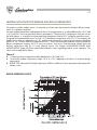
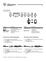
1
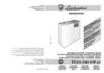
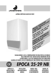
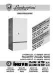
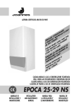
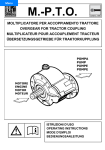
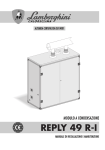
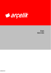
AZIENDA CERTIFICATA ISO 9001
"
RE 'USO
A
N D
EG ALE
S
N U
E
CO AN
I
TH
S "M
T
A
A
E
H D
EG TO T
PR SER TEN
E T NDE
R
U
U A
N
L'I SIG.
E S IS H
K
A L"
E
AL
E MNUA USER AD D L
S
A A
E
ILIDRIO
PLE E M THE
B
A
S
A
O
"U ER T
AM USU
A
V
L
L A "
O
AN RLE USO
G
A
O
TENREG L DE
T
A
AR
U
N
G
E AN
RE O"
NT E US
"M
E
R
D
VO AL TE
FA ANU TEN
U
"M SR.
AO
CALDAIA MURALE A GAS A CONDENSAZIONE ISTANTANEA
WALL-HUNG GAS INSTANTANEOUS CONDENSING BOILER
CALDERA MURAL A GAS CON CONDENSACIÓN INSTANTÁNEA
CALDEIRA DE PAREDE A GÁS DE CONDENSAÇÃO INSTANTÂNEA
24-28 MC W TOP /IT
MANUALE DI
INSTALLAZIONE E
MANUTENZIONE
INSTALLATION
AND MAINTENANCE
MANUAL
MANUAL PARA
LA INSTALACIÓN Y
EL MANTENIMIENTO
MANUAL DE
INSTALAÇÃO E
MANUTENÇÃO
40
INDEX
PAGE
GENERAL INSTRUCTIONS __________________________________________________
DESCRIPTION ____________________________________________________________
INSTALLATION ____________________________________________________________
DIMENSIONS mm. ________________________________________________________
TECHNICAL FEATURES _____________________________________________________
HYDRAULIC CONNECTION ________________________________________________
MAIN COMPONENTS _____________________________________________________
HYDRAULIC CIRCUIT _______________________________________________________
ELECTRICAL CONNECTIONS - WIRING DIAGRAMS ____________________________
WIRING DIAGRAM ________________________________________________________
FLUE EXHAUST INSTALLATION ______________________________________________
OPERATION ______________________________________________________________
IGNITION ________________________________________________________________
MAINTENANCE __________________________________________________________
CONTROL PANEL _________________________________________________________
ADJUSTMENTS ___________________________________________________________
OPERATING SEQUENCE ___________________________________________________
LIST OF PARAMETERS INDICATED BY 1st FIGURE ON DISPLAY ____________________
DATA DISPLAY (MONITOR system) ___________________________________________
FAULT CODE _____________________________________________________________
RESETTING _______________________________________________________________
PARAMETER DISPLAY AND MODIFICATION (ACCESS CODE) ____________________
GAS VALVE ADJUSTMENT __________________________________________________
VARYING FAN R.P.M. ______________________________________________________
NOZZLE CALIBRATION ____________________________________________________
BURNER PRESSURE CURVES - OUTPUT _______________________________________
TRANSFORMATION NATURAL GAS - B/P ____________________________________
HEATING WITH OUTDOOR SENSOR AND ROOM THERMOSTAT _________________
41
42
43
44
44
45
46
47
48
52
53
57
58
59
63
64
65
66
67
68
69
69
72
72
73
73
74
75
Congratulations...
...on an excellent choice.
We thank you for the preference accorded to our products.
LAMBORGHINI CALORECLIMA has been actively present in Italy and throughout the world since 1959
with a widespread network of agents and concessionary agents to constantly guarantee the presence of
our product on the market. Alongside this is the support of a technical service, “LAMBORGHINI SERVICE”,
which is entrusted with the qualified servicing of the product.
For the installation and positioning of the boiler:
CAREFULLY OBSERVE THE LOCAL REGULATIONS IN FORCE
41
GENERAL INSTRUCTIONS
● This booklet constitutes an integral and essential part of the product.
Read carefully the instructions contained in this booklet as they provide important directions regarding the
safety of installation, use and maintenance. Preserve this booklet with care for any further consultation.
The installation of the boiler must be carried out in compliance with current regulations, according to the
instructions of the manufacturer and by qualified personnel. An incorrect installation can cause injury or
damage to persons, animals and objects, for which the manufacturer cannot be held responsible.
● After removing the packaging materials, check the content integrity. In case of doubt, do not use the unit
and contact the supplier. The packaging material (wooden crates, nails, clips, plastic bags, foam, etc.)
must not be left within reach of children as they are potential sources of danger.
● This boiler is designed to heat water to a temperature below boiling (atmospheric pressure). It must be
connected to a heating system compatible with its performances and output.
● This appliance should be destined only for the use for which it has been expressly envisaged. Any other
use is to be considered improper and therefore dangerous. The manufacturer cannot be considered
responsible for any damages caused from improper, erroneous or unreasonable use.
ALL INSTALLATION, MAINTENANCE AND GAS CONVERSION OPERATIONS MUST BE CARRIED OUT BY
AUTHORISED SKILLED TECHNICIANS.
TO ENSURE THAT BOILER IS INSTALLED CORRECTLY AND THAT IT FUNCTIONS PROPERLY, WE RECOMMEND
THAT ONLY LAMBORGHINI ACCESSORIES AND SPARE PARTS BE USED.
ON NOTICING THE SMELL OF GAS DO NOT TOUCH ANY ELECTRIC SWITCH. OPEN DOORS AND WINDOWS.
SHUT OFF THE GAS COCKS.
INSTALL THE BOILER ON WALLS WHICH ARE AS WIDE AS OR WIDER THAN THE BOILER ITSELF.
42
DESCRIPTION
FUTURIA L 24-28 MC
Perfectly air-tight with respect to its surroundings, this unit is suitable for heating water to temperatures below
boiling point at atmospheric pressure. Fully automatic, the FUTURIA L boiler is governed by an electronic
microprocessor-operated control box.
Continuous power modulation is effected both on the heating circuit and the hot water circuit, by means of an
electronic board controlling fan r.p.m.
Combustion analysis (to be measured at the flue base on the appropriate points) allows adjustment of gas
delivery so that the right air/gas mix is always obtained. Each variation in fan r.p.m. (and the resulting airflow) corresponds to a variation in the gas delivery rate.
This operation ensures a constant air-gas ratio whatever the flame intensity, thus guaranteeing maximum
combustion efficiency and hygiene under all working conditions.
The electronic board also provides:
-
3-way valve and circulation pump efficiency test; this prevents the lock-out that might otherwise occur
when the boiler remains idle for a prolonged period (the valve and pump are operated for a set time every
24 hours).
-
Anti-freeze device:
when the heating water temperature falls below 10°C the circulation pump comes
on. If temperature continues to fall the burner will ignite at 3°C, burning at
minimum. It will be switched off when the water is reheated to 10°C. This is why
the boiler must be left connected to the power supply even when it is not in
use.
-
Board memory:
The control box microprocessor will memorise and signal any anomalies. This
information is stored on the memory even when the power is off and can be
recalled by connecting up to a PC.
-
Temperature-adjustable operation with external temperature compensation function (where installed).
43
INSTALLATION
To be carried out by qualified personnel.
The system must be installed in an area free from corrosive vapours and must comply with the legal standards
in force regarding evacuation of combustion by-products. It is especially recommended that standards concerning
safety, construction and flue positioning be strictly observed.
SYSTEM START-UP
● Open windows and doors and do not light any naked flames.
● Bleed the air
● Check that there are no gas leaks (use soapy water or an equivalent product).
Before installing the boiler it is important to remove any impurities from the water supply pipes; use air or
inert gas.
Make sure that the boiler is suitable for the type of gas available to the user.
44
DIMENSIONS mm.
Ø100 conc.
Ø80 sdop.
120
242
93
900
asp. Ø80
220
190
450
420
TECHNICAL FEATURES
Hot water
supply Expan.
Weight
Heating
Hot
water
Continuous Min. tank
Output Output
Output Output
Input
Input
supply supply
50/30°C 80/60°C
50/30°C 80/60°C circuit circuit ∆30°C
min. max.
kW kcal/h kW kcal/h kW kcal/h kW kcal/h kW kcal/h kW kcal/h bar bar bar l/min. l/min. l kg
Thermal capacity
MODEL
FUTURIA
Operating
pressure
Min. thermal capacity
L 24 MC
25,0 21.500 25,75 22.145 24,5 21.070 8,8 7.568 9,33 8.022 8,98 7.719
3
0,2 6 11,7
2
8
72
L 28 MC
29,0 24.940 29,8 25.634 28,4 24.390 10 8.600 10,66 9.168 10,09 8.677
3
0,2 6 13,6
2
8
72
Boiler version: mod. C type C13-C33-C43-C53
Category: II 2H3B/P
Max. water temperature 90°C
Rated gas pressure: Natural gas 20 mbars
B 30 mbar
P 37 mbar
CIRCULATING PUMP FEATURES
Delivery/pressure available at the system
700
Residual pressure (mbar)
650
600
550
500
450
400
350
300
250
200
150
100
50
0
0
100
200
300
400
500
600
700
800
900
Delivery (lt/h)
1000
1100
1200
1300
1400
1500
45
HYDRAULIC CONNECTION
Fit the supporting hooks and attach the assembly template, moving it up to the wall; fit all the pipes, starting
with the end pipe fittings already mounted on the template: system supply, system return, cold water, hot water,
any gas pipes and electric mains leads with room thermostat.
Once the pipes have been fitted, the end pipe fittings can be removed and ordinary caps fitted, ready for
hydraulic tests to be carried out. The template can be removed or, if left in place, will be embedded in the wall
once finishing operations have been completed (plaster and tiles); only the two supporting hooks will protrude
from the wall, as well as an opening for the connections. Attach the boiler to the hooks through the holes at the
back of the frame, push it up against the finished wall and fit the two lock nuts onto the hooks.
Make the necessary hydraulic connections using the pipes/tubes supplied, cutting them to the right length,
depending on the distance between the fittings on the boiler and those on the template embedded in the wall.
450
26
CONDENSATE DISCHARGE
The condensate which forms inside the boiler must
be discharged. The boiler is therefore fitted with a
water trap. The water trap fitting must be connected
to a outlet in PVC. It is advisable to insert another
water trap on the discharge line before entry into
the waste water system.
398
894
Important: should the condensate discharge pipe
(supplied with the boiler) be replaced, always
use a pipe with an internal diameter of at least
13 mm.
The coo condensate unloading in endowment is
of Ø 25 mm external
930
GS
G
C
F
M
R
SC
37
LEGEND
C
G
Hot water
Gas
F
AE
M
R
GS
SC
Boiler water supply
Electrical supply
System delivery
System return
Holding hooks
Condensate discharge duct
20
AE
52
50
65
58 58
65
50
Ø 1/2”
Ø 3/4” (in the boiler)
Ø 1/2” (in the G./connections)
Ø 1/2” (cold)
Ø 3/4”
Ø 3/4”
Ø 10 mm.
Ø 80 mm.
NOTE:
Preview hydraulic female connections.
46
MAIN COMPONENTS
1
2
15
4
6
16
3
19
7
20
LEGEND
1
2
3
4
5
6
7
8
9
10
11
12
13
14
15
16
17
18
19
20
Air bleed valve
Control electrode
Fan
Ignition electrodes
Control box
Ignition transformer
Fume pressure switch
NTC 2 return sensor
NTC 3 hot water sensor
Water trap for condensate discharge
Circulating pump
Lack of water pressure switch
Filling cock
Hydrometer
NTC 1 delivery sensor
Expansion tank
3-way valve
Water-heater
Gas valve
Aluminium boiler body
A
B
C
D
E
3/4” Ø system delivery
1/2” Ø hot water outlet
3/4” Ø gas inlet
1/2” Ø cold water inlet
3/4” Ø system return
18
8
10
1
9
12
11
17
A
B C
D E
13
14
5
6
47
HYDRAULIC CIRCUIT
1
12
6
21
2
3
5
4
8
10
9
16
7
18
20
11
15
1
19
13
14
LEGEND
A
B
C
D
E
1
2
3
4
5
6
7
8
Gas
ICold water inlet
Hot water outlet
System delivery
System return
Air bleed valve
Control electrode
Nozzle connection
Ignition transformer
Ignition electrodes
System delivery control sensor
System return control sensor
Fan
E
17
D C A B
9
10
11
12
13
14
15
16
17
18
19
20
21
Air pressure switch
Gas valve
Water trap for condensate discharge
Expansion tank
Circulating pump
Hot water sensor
3-way valve
Water-heater
Filling cock
Safety valve
Drain tap
Lack of water pressure switch
Air bleed tap
48
ELECTRICAL CONNECTIONS - WIRING DIAGRAMS
The boiler must be connected to an earthed, single-phase 230V-50 Hz mains supply by means of a three-wire
cable, ensuring that connections to the LINE and NEUTRAL terminals are made correctly.
A bipolar switch must be used with contacts opening to at least 3 mm.
The power lead must only be replaced by another with the following characteristics: “HAR H05 vv-F” 3x1.00
mm2. (Only LAMBORGHINI accessories and spare parts be used).
Installation must be made in compliance with safety REGULATIONS IN FORCE.
Make a good earth connection.
Voltage
Frequency
V
Hz
230
50
Absorbed
power
Protection
index
Noise level
W
IP
dB (A)
150
X 4D
<50
To gain access to the electrical panel which houses the power supply terminal block and any connection to an
ambient temperature thermostat, proceed as follows:
● Disconnect the boiler power supply.
● Undo the screws 1 of the plastic front panel (Fig. A).
1
1
Fig. A
49
● Remove the plastic front panel attached to the sides by small bolts (Fig. B).
Fig. B
● Undo the screws 2 fixing the panel to the sides (Fig. C), the panel will open by about 20° and will stop in
this position (Fig. D).
2
Fig. C
2
Fig. D
50
● To lower completely the panel it is first necessary to move it up and then lower it until the locking point is
reached (Fig. E).
1st Move it up
Fig. E
2nd Lower
● To remove the cover from the panel unscrew the bolts 3 (Fig. F).
3
3
3
3
Fig. F
51
● It is now possible to have access to the terminal board (M) for maintenance or for possible connections
(see wiring diagram page 52) of room thermostat or outdoor sensor (Fig. G).
M
Fig. G
● To gain access to the display or for maintenance, it is possible to remove the holder (P), to which all
electrical components are connected, by unscrewing the bolts 5 (Fig. H).
5
5
5
5
Fig. H
P
52
WIRING DIAGRAM
AZZURRO - BLUE - AZUL - AZUL
TRA
AZZURRO
AZZURRO
MARRONE
MARRONE
(VITE DI TERRA)
MARRONE - BROWN - MARRÓN - MARROM
GRIGIO - GREY - GRIS - CINZENTO
FA
E.R.
E.A.
NERO - BLACK - NEGRO - PRETO
ROSSO - RED - ROJO - VERMELHO
X4
M1
N
BIANCO - WHITE - BLANCO - BRANCO
TA
SE
SE
C
L N N1 L1
1
2
MARRONE
GRIGIO
MARRONE
B/X2
A/X2
1 2 3 4 5 6 7 8 9 10 11 12 13
GRIGIO
X3
1 2 3 4 5 6
3
4
5
6
C
NC
NA
C
NC
NA
IG
G/VERDE
AZZURRO
MARRONE
MARRONE
VN
AZZURRO
NERO
PA
SS
ROSSO
EI
MARRONE
VD
BIANCO
GRIGIO
MARRONE
NERO
NERO
SR
AZZURRO
ROSSO
MARRONE
MARRONE
AZZURRO
AZZURRO
MARRONE
SM
AZZURRO
P
MARRONE
AZZURRO
MARRONE
MARRONE
NERO
VG
AZZURRO
NERO
PH2O
NERO
LEGEND
P
PSG
PA
PH20
E.A.
E.R.
TRA
IG
VG
FA
TA
SE
MARRONE
AZZURRO
G/VERDE
TA
G/VERDE - G/GREEN - VERDE - VERDE
AZZURRO
Fuse
L
1 2
1
System circulating pump
Safety gas press. switch
Air pressure switch
Water pressure switch
Ignition electrode
Control electrode
Transformer
Main switch
Gas valve
Anti interference filter
Room thermostat (optional)
External sensor (optional)
SR
SS
SM
M1
VD
EI
VN
A/X2
B/X2
X3
X4
C
Return sensor
Hot water sensor
Delivery sensor
Terminal board
3 way valve
Summer/Winter switch
Fan
5 poles connector
8 poles connector
6 poles connector
2 poles connector
Connector
TA
53
FLUE EXHAUST INSTALLATION
CONCENTRIC FLUE EXHAUST PIPE - STANDARD APPLICATIONS
Flue exhaust pipe lengths are referred to the electric fan pre-calibration, i.e. 5500 rpm with concentric flue
pipe Ø 100/60.
Max. 3000
93
100
100
Max. 3000
242
900
100
Ø100
Min. 500
FLUE EXHAUST PIPE FROM A WALL
450
Elbow fitted at 90°: 1 m. length reduction
Elbow fitted at 45°: 0.5 m. length reduction
WARNING:
● Do not calibrate fan speed (rpm) higher than what is necessary.
● Use only air intake/flue exhaust kits produced by Lamborghini Caloreclima.
420
54
Max. 4000
CONCENTRIC FLUE EXHAUST PIPE FROM THE ROOF
Ø 100/60 conc.
900
93
450
Elbow fitted at 90°: 1 m. length reduction
Elbow fitted at 45°: 0.5 length reduction
WARNING:
● Do not calibrate fan speed (rpm) higher than what is necessary.
● Use only air intake/flue exhaust kits produced by Lamborghini Caloreclima.
55
DOUBLE FLUE PIPE
The flue exhaust pipe should slope slightly upward (about 3%), to allow possible condensation to be collected
in the boiler.
Flue exhaust pipe length (see table) is referred to the electric fan speed of 5500 rpm with pipe diameter Ø 80
or Ø 60.
Max.length
Intake + Exhaust
Elbow fitted at 90°
Pipe diameter Ø 80 mm
50 mt.
0,6 mt.
Pipe diameter Ø 60 mm
20 mt.
2 mt.
WARNING:
● Do not calibrate fan speed (rpm) higher than what is necessary.
● Use only air intake/flue exhaust kits produced by Lamborghini Caloreclima.
56
FLUE EXHAUST PIPE INSTALLATION - SPECIAL APPLICATIONS
If types of flue exhaust different from the standard ones previously decribed are necessary, it is possible to
increase the concentric exhaust length Ø 100/60 or the double pipe exhaust length Ø 60, by adjusting the
electric fan speed (see paragraph “Parameters modification”, page 69). The maximum obtainable fan speed
is 5800 rpm, while the maximum exhaust length is referred to the following table:
Fan speed 5800 rpm
Concentric flue exhaust pipe Ø 100/60 mm
Concentric pipe max. length 10 mt
Double pipe Ø 60 mm
Intake + exhaust max. length 35 mt
NOTE: For Ø 80 mm double pipe, only standard application is applied.
57
OPERATION
When the unit is switched on (or when it is reset), and where no heat has been requested, the system runs
through the following procedure:
●
●
●
●
5 second safety pause
3-way valve activated for 15 seconds
circulator activated for 60 seconds
circulator and 3-way valve switched off
This cycle is run every 24 hours and 24 hours after the last heat request. The above operations ensure that the
components are put in motion at least once a day.
HEATING
The heating start-up cycle, after a period of inactivity, is as follows:
●
●
●
●
●
●
●
3-way valve activated for 15 seconds
pump activated
air pressure switch contacts checked (they must be closed)
fan switched on
when heat is requested pre-ventilation begins
ignition transformer switched on and gas valve opened
sif flame detection reveals normal operation the fan runs for a few seconds at maximum power and then
modulation begins
When heat is no longer requested the burner is switched off while the pump continues to run for 3 minutes
(post-circulation time). The 3-way valve is then disactivated.
If the flame is not detected the pre-ventilation/ignition cycle is repeated after a set safety period has elapsed
(repeated up to 3 times, after which the unit is shut down).
HOT WATER PRODUCTION
When hot water is requested the 3-way valve switches immediately to the hot water circuit. When the burner
is switched off the pump continues running for another two minutes after which it shuts down. A hot water
request is detected by a temperature sensor on the hot water circuit heat exchanger; this trips the hot water
production system when the sensor-detected temperature is lower than the phase n° 1 setting.
Modulation takes place immediately and proceeds as a function of boiler water return temperature.
When producing hot water, the burner goes out when the sensor-detected temperature exceeds set temperature.
DUAL FUNCTION (HOT WATER + HEATING)
If there is a request for hot water when heating is in progress, the 3-way valve diverts the water flow towards
the hot water heat exchanger (hot water has precedence over heating). When hot water is no longer required
the burner goes out and the pump continues running for another two minutes, then stops. The three-way valve
then diverts the water flow back to the heating circuit.
The pump is then restarted and the heating function put back into operation.
58
IGNITION
SYSTEM FILLING
Bring the 3-way valve into the manual position. Open the inlet valve slowly until the system reaches a working
pressure (indicated on the hydrometer) of approximately 1 bar, then close it.
Verify that the automatic air bleed valves have their cap loosened, run the circulator to eliminate the any air in
the circuit, proceeding as follows:
press the ON button on the control panel (the display lights up) and activate the heating function (Summer/
Winter switch set to Winter) to start the circulator. Press the OFF button to stop the circulator; repeat the
procedure until all the air had been vented.
Reset the 3-way valve to the “automatic” position.
IGNITION
Open the gas cock, press the ON button. The burner will ignite automatically (the heating and hot water
functions are set by the manufacturers).
Should the unit fail to ignite there will be another three ignition attempts after which there will be a shutdown
(the display will flash 2 - 02). Press RESET: if the unit still fails to ignite contact the technical assistance service.
59
MAINTENANCE
To remove the casing front panel (1) and acceed to the internal components, it is first necessary to remove the
plastic front panel (2)* and open the conmtrol board (3)*.
Undo the screws (4) and remove the casing panel (1) fixed to the sides by four small pins.
If the lower closing panel (5) is to be removed, it is necessary to undo the four screws (6), doing this with care
as the screws hold the lower closing panel.
4
4
1
3
2
6
6
6
6
5
NOTE: To remove the plastic front panel and open the control board see paragraph “Wiring diagrams”,
page 48.
60
IGNITION AND CONTROL ELECTRODES INSPECTION
To gain access to ignition and control electrodes, remove the inspection cover on the sealed chamber (Fig. A).
C
● Undo the screws (1) and remove
the inspection cover (C).
● The electrodes can be removed
by undoing the screws (2).
1
EC
2
EA
EC Control electrode
EA Ignition electrode
2
Fig. A
INSPECTION OF THE RETARDERS INSIDE THE COMBUSTION CHAMBER
To inspect the retarders situated inside the sealed chamber, it is first necessary to unfit the lower gas pipe (Fig. B).
Fig. B
61
Extract syphon (S) and unscrew the syphon holder (CS), sealed by an O-ring, from the fume tank (Fig. C).
OR
CS
Fig. C
S
Then remove the lower cover of the sealed chamber (CC) by undoing the screws (1) and pull it outward (Fig.
D).
CC
1
1
1
Fig. D
62
Unscrew fixing nuts(D) from the fume tank (VS). Then, rotating the fume tank as indicated in figure E, it can be
disconnected from the fume pipe and extracted from the sealed chamber.
VS
D
Fig. E
It is now possible to inspect the retarders from the inside of the combustion chamber for maintenance (Fig. F).
SX
DX
Fig. F
63
CONTROL PANEL
7
6
5
4
3
8
LEGEND
1
2
3
4
5
6
7
8
9
10
“-” key to reduce settings
“+” key to increase settings
“memo” key to save data
“sequence” key to select parameters to be displayed
“program” key to select the program
Data display
Boiler “reset” key
Summer/winter selector
Main switch
Hydrometer
2
1
9
10
64
Button
Function
Button
Function
ON/OFF
ON/OFF SWITCH
SUMMER/WINTER SWITCH
BOILER RESET
PROGRAM SELECTOR
(DISPLAY)
SEQUENZA/STEP
SELECTS PARAMETERS TO BE
DISPLAYED
ENTERS DATA
INCREASES SETTING
DECREASES SETTING
RIARMO/RESET
PROG./MODE
MEMO/STORE
+
-
ADJUSTMENTS
ADJUSTING HOT WATER TEMPERATURE
ADJUSTING HEATING TEMPERATURE
1) Open a hot water tap (temporarily).
2) Press (MODE). An indicator light on the left-hand
display comes on.
3) Press (STEP) to phase 1
1) Press (MODE). An indicator light on the left-hand
display comes on.
2) Press (STEP) to phase 4
4) Press the (+) (-) buttons to modify the hot water
temperature.
5) Press (STORE) to memorise the data.
6) Press (MODE) twice to enter the new temperature
setting.
3) Press the (+) (-) buttons to modify the heating temperature setting.
4) Press (STORE) to memorise the data.
5) Press (MODE) twice to enter the new temperature
setting.
The boiler is ready to function for heating and hot water supply.
65
OPERATING SEQUENCE (display only)
a
1 FIGURE
a
2 FIGURE
Button
Function
Button
Function
ON/OFF
ON/OFF SWITCH
SUMMER/WINTER SWITCH
BOILER RESET
PROGRAM SELECTOR
(DISPLAY)
SEQUENZA/STEP
SELECTS PARAMETERS TO BE
DISPLAYED
ENTERS DATA
INCREASES SETTING
DECREASES SETTING
RIARMO/RESET
PROG./MODE
MEMO/STORE
+
-
During boiler operation the first figure on the digital display indicates the sequence step while the second gives
the temperature of the water in the boiler.
E.g.
means that the unit is heating at a delivery temperature of around 80°C.
Step
0
1
2
3
4
5
6
7
8
9
Function
pause, no heat required
pre-ventilation
ignition
burner ignited (heating system mode)
burner ignited (hot water mode)
air pressure switch control
burner off (water temp. more than 5°C warmer than setting)
post-circulation pump in heating mode
post-circulation pump in hot water mode
burner off because of fault (see shutdown code)
66
LIST OF PARAMETERS INDICATED BY 1st FIGURE ON DISPLAY (Values can be adjusted by the user)
To gain access to the PHASE number press the MODE button once (an indicator light to the right of the 1st figure
comes on). Press STEP to display all the available PHASES.
Step
N° display
Parameter value
display
Example:
indicator light
Phase N°
Parameter
1
Hot water temperature
2
Hot water system
Value range
from 40 to 65 °C
00 = domestic hot water excluded
01 = 5°C hysteresis + pump
continuously on Hot water
02 = 5°C hysteresis
03 = 10°C hysteresis
04 = 20°C hysteresis
05 = 30°C hysteresis
3
Heating
00 = heating disabled
01 = heating enabled
02 = heating enabled, pump
running continuously
4
Water delivery temperature
from 20 to 90°C
To exit the PHASE list press
twice.
Default settings
55
02
01
80
67
DATA DISPLAY (MONITOR system)
Real-time data (not modifiable) regarding unit operation can be checked on the monitor. Press MODE twice (a
flashing indicator light appears to the right of the 1st figure). Press STEP to display all the available PHASES.
Phase N°
Parameter
1
2
3
4
25
6
7,8
Water delivery temp.
Return temp.
Hot water temp.
Outdoor temp. (*)
Sistema
acqua calda sanitaria
Fume
temp.
Set or calculated delivery temp.
Parameters used by the installer
Notes
°C
°C
°C
°C
°C
(*) Parameter displayed if connected to sensor (optional)
To exit the DATA DISPLAY program press
once
Unavailable
With OPTIONAL outdoor sensor
Access code input
68
FAULT CODE (read-only display)
The boiler control box is equipped with a microprocessor that memorises and signals any faults or shutdowns.
The fault type is indicated by a code.
The meaning of each code is given in the table below:
1st Figure
2nd Figure
0
1
2
4
4
4
4
4
4
4
4
4
4
4
4
4
4
4
4
4
4
4
4
4
4
4
5
5
5
9
9
9
9
00
01
02
03
04
05
06
07
10
11
13
14
15
16
17
24
26
30
31
32
36
37
41
42
44
60
08
28
29
12
18
19
25
Fault
Flame detection circuit fault
24 V short circuit
No detection, no flame on burner
Board fault
Internal board fault (e.g. power failure)
Board fault
Board fault
Board fault
Board fault
Board fault
Board fault
Board fault
Board fault
Board fault
Board fault
NTC1/NTC2 connection switched over
Minimum gas pressure (at pressure switch)
Difference ∆T between T1 and T2 exceeded (>35 °C)
NTC1 short circuit
NTC2 short circuit
NTC1 open
NTC2 open
Board fault
Board fault
Board fault
Board fault
Air pressure switch failure
Fan not working, no tachometer signal
Fan continues running, erroneous tachometer signal
No-water pressure switch
TST tripped (>98°C)
Return temperature T2 too high (>88°C)
Temperature T1 varies too quickly (T1 = delivery temperature)
69
RESETTING
Should there be a fault the system will shut down and flash the fault type on the display.
Check for proper operating conditions (gas cock open, proper feed pressure etc.) and press RESET. Should the
fault persist contact your local LAMBORGHINI SERVICE CENTRE.
PARAMETER DISPLAY AND MODIFICATION (ACCESS CODE)
By pressing MODE and STEP simultaneously the letter C will appear on the display. Keeping these buttons
pressed, enter the access code (62) by means of the + and – keys. Press STORE to memorise the code (the
display will flash twice). Press MODE to highlight the PHASE number on the display. Then press STEP to display
the list of PHASES.
When setting has been
completed press
Phase N°
1
2
Parameter
Range
Tset Hot water temperature
From 40°C to 65°C
D.H.W. System (NTC3 present)
00 = Hot water off
01 = Hot water on + pump running
continuously with hysteresis of -5°C on
Tset (Phase 1)
02 = Hot water on with hysteresis of -5°C
on Tset (Phase 1)
03 = Hot water on with hysteresis of -10°C
on Tset (Phase 1)
04 = Hot water on with hysteresis of -20°C
on Tset.(Phase 1)
05 = Hot water on with hysteresis of -30°C
on Tset.(Phase 1)
70
When setting has been
completed press
Phase N°
Parameter
Range
3
Central heating system
00 = Central heating off
01 = Central heating on
02 = Central heating on and pump in cont.
mode
4
Delivery temperature (T1)
From 20°C to 90°C
5
T1foot (minimum heating temperature)
From 15°C to 25°C (recommended 15°C)
6
T4 minimum (settable outdoor sensor temperature)
From -20°C to +10°C
7
Pause temp. for heating re-ignition
From 15°C to 30°C
8
Parallel shift (with outdoor sensor and
boiler timer)
9
Central heating hysteresis
From 5°C to 15°C
A
Heating re-ignition waiting time
From 0°C to 30 (x10.2 seconds)
b
Post-circulation time. Pump heating
From 3 to 99 minutes
C
PWM pump
Do not use
on-
From 0°C to 30°C (on Tset)
Boiler type
1 figure (as in heating)
0x = room thermostat
1x = NTC4 sensor (outdoor sensor)
2 figures (as in Hot water)
x0 = 3-way valve
x1 = Hot water pump - Do not use
x2 = inverted 3-way valve - Do not use
E
Fan speed control
00 = modulation working
From 01 to 100% manual fan speed control.
Chimney-sweep function.
F
Min/max r.p.m. in heating mode
From 10 to 60 (x 100)
d
71
When setting has been
completed press
Phase N°
Parameter
Range
G
Max r.p.m. in heating mode
from 00 to 90 (units)
H
Max r.p.m. in Hot water mode
from 10 to 60 (x 100)
I
Max r.p.m. in Hot water mode
from 00 to 99 (units)
J
Min. r.p.m.
from 05 to 60 (x 100)
L
Min. r.p.m.
from 00 to 99 (units)
n
Start r.p.m.
R.p.m. settable at start between 80 and 100%
of absolute value.
To exit the program at any time just press
twice.
72
GAS VALVE ADJUSTMENT
The boilers leave the factory already set to their minimum and maximum output and therefore do not need to
be set when installed.
Should the settings need to be modified to adapt them to installation requirements it will be necessary to
change fan r.p.m. and reset the CO2 value to between 8,8-9% for natural gas and 9,8÷10% for B/P.
In the event of gas valve replacement, proceed as follows:
1
2
3
4
5
6
7
8
Insert a combustion instrument.
Position the switch to SUMMER or WINTER and open a
tap on the D.H.W. circuit.
Read the instructions for displaying and modifying the
parameters (access code) on the use and maintenance
manual, page 33.
Select step H and J, set fan rpm to the maximum figure.
Adjust the gas flow-rate by acting on screw B until the
CO2 value is between 8,8-9% for natural gas and
9,8÷10% for B/P.
Select step H and J, set fan rpm to the minimum figure.
Adjust the gas flow-rate by acting on screw A until the
CO2 value is between 8,8-9% for natural gas and
9,8÷10% for B/P.
Select step H, set the maximum fan rpm.
Select step J, set the minimum fan rpm.
When adjustments have been completed, press PROGRAM
button to display again the standard functions.
Legend
A
B
Minimum heat delivery adjustment screw
Maximum heat delivery adjustment screw
VARYING FAN R.P.M.
–
–
–
–
–
Set the access code (62) (see page 69).
Press MODE.
Press STEP to display the relative PHASE. N° (F-G).
Use the +/- keys to set the desired r.p.m.
Press STORE to enter the variation.
73
GAS - NOZZLE CALIBRATION
The boilers leave the factory calibrated and predisposed to operate with NATURAL GAS or B/P. For the precalibrations effected, see the related table below:
Model
L 24 MC
NATURAL
GAS
L 28 MC
G20 - 20 mbar
L 24 MC
B/P
L 28 MC
CO2 %
Gas type
Min
Max
8,8
9,0
Flow-rate
Burner
jet
Air
diaphragm
Calorific
value (*)
m3/h
Ø mm
Ø mm
Kcal/h
2,62
4,9
21,0
8.550
3,05
0,765 (G30)
9,8
G30 - 30 mbar
G31 - 37 mbar
10,0
1,01 (G31)
0,877 (G30)
1,15 (G31)
5,4
23,5
3,8
21,0
4,2
23,5
29.330
22.360
29.330
22.360
* = at 1013 mbar, 15°C
BURNER PRESSURE CURVE - OUTPUT
6000
5800
5500
Field of job previewed for
operation like paragraph
“FLUE EXHAUST PIPE
INSTALLATION - SPECIAL
APPLICATIONS” page 56.
Electric fan speed
5000
4000
Futuria L24 MC
Futuria L28 MC
3000
2000
1000
kW
8
10
12
8.8 10.9
14
16
18
20
22
24
26
25.0
30
29.0
74
TRANSFORMATION NATURAL GAS - B/P
If the boiler is to be converted from natural gas to LPG (or vice-versa), use only original conversion kits.
For the conversion proceed as follows:
GS
2
● Undo screws (1) and bolts (2)
● Remove the gas pipe (G)
G
● Unscrew the gas jet (GS) and
replace by the new one
1
Gas valve calibration must be effected as indicated at page 72 and considering the data indicated in the
following table.
Model
L 24 MC
Gas type
NATURAL
GAS
L 28 MC
G20 - 20 mbar
L 24 MC
B/P
L 28 MC
CO2 %
Min
Max
8,8
9,0
Flow-rate
Burner
jet
Air
diaphragm
Calorific
value (*)
m3/h
Ø mm
Ø mm
Kcal/h
2,62
4,9
21,0
3,05
5,4
23,5
3,8
21,0
4,2
23,5
8.550
0,765 (G30)
G30 - 30 mbar
G31 - 37 mbar
9,8
10,0
1,01 (G31)
0,877 (G30)
1,15 (G31)
29.330
22.360
29.330
22.360
75
HEATING WITH OUTDOOR SENSOR AND ROOM THERMOSTAT
For proper use of the outdoor sensor it is compulsory to fit the room thermostat which adjusts delivery temperature T1 to ambient conditions.
For each outdoor temperature reading between the set T4 (via parameter n° 6, adjustable between –20°C and
+10°C) and 30°C there corresponds a delivery temperature T1 between the T1 temperature set by the user on
the boiler (phase. n° 4) and the minimum operating temperature fixed at 55°C (see boiler operation curve).
The graph-illustrated example shows T4 set to -10°C and delivery temperature set to 75°C. If, for example, the
outdoor sensor detects a temperature of –5°C and the room thermostat is requesting heat (contact closed) the
boiler will “try” to reach a delivery temperature of 65°C. If the room thermostat continues requesting heat the
delivery temperature increases by 10°C every ten minutes. Vice versa, if the thermostat contact opens the
delivery temperature falls by 1°C each elapsed minute. The chapter “PARAMETER DISPLAY AND
MODIFICATION” (page 69) shows admissible parameter values regarding outdoor sensor operation. The
values must be adjusted as follows:
Phase N°
5
6
b
T1 heating minimum temperature adjustable between 15°C and 25°C.
T4 minimum outdoor temperature range –20°C to +10°C (adjusted on the basis of minimum design
temperature)
BOILER TYPE: adjusted to 00 (fixed): adjustment valid for installation of room temperature thermostat with
outdoor sensor.
BOILER OPERATION CURVE
-VI
0444 352000
BRUCIATORI
CALDAIE MURALI E TERRA A GAS
GRUPPI TERMICI IN GHISA E IN ACCIAIO
GENERATORI DI ARIA CALDA
TRATTAMENTO ACQUA
CONDIZIONAMENTO
Le illustrazioni e i dati riportati sono indicativi e non impegnano. La LAMBORGHINI si riserva il diritto di apportare senza
obbligo di preavviso tutte le modifiche che ritiene più opportuno per l'evoluzione del prodotto.
The illustrations and data given are indicative and are not binding on the manufacturer. LAMBORGHINI reserves the right to
make those changes, considered necessary, for the improvement of the product without forwaming the customer.
Las ilustraciones y los datos son indicativos y no comprometen. LAMBORGHINI se reserva el derecho de realizar sin preaviso
todas las modificaciones que estime oportuno para la evolución del producto.
As ilustrações e os dados existentes são indicativos e não compromissivos. A LAMBORGHINI reserva-se o direito de efectuar,
sem a obrigação de pré-aviso, todas as modificações que considerar necessárias para a melhoria do produto.
LAMBORGHINI CALOR S.p.A.
VIA STATALE, 342
44040 DOSSO (FERRARA)
ITALIA
TEL. ITALIA 0532/359811 - EXPORT 0532/359913
FAX ITALIA 0532/359952 - EXPORT 0532/359947
Cod. 97.50521.0 06/2002
AZIENDA CERTIFICATA ISO 9001
IT
CALDAIA MURALE A GAS A CONDENSAZIONE
ISTANTANEA
MANUALE PER L‘UTENTE
GB
WALL-HUNG GAS INSTANTANEOUS
CONDENSING BOILER
USER MANUAL
ES
CALDERA MURAL A GAS
CON CONDENSACIÓN INSTANTÁNEA
MANUAL PARA EL USUARIO
PT
CALDEIRA DE PAREDE A GÁS
DE CONDENSAÇÃO INSTANTÂNEA
MANUAL DO UTENTE
2
Alla cortese attenzione del sig. INSTALLATORE:
Consegnare il presente manuale d’uso all’UTENTE
10
For the attention of the INSTALLATION TECHNICIAN:
make sure that this manual is handed over to the USER
18
A la atención del sr. INSTALADOR:
Entregar el presente manual para el uso al USUARIO
26
Àtenção do Sr. INSTALADOR:
Entregue este manual de uso ao UTENTE
24-28 MC W TOP U/IT
10
INDEX
PAGE
GENERAL INSTRUCTIONS _________________________
INSTRUCTIONS FOR THE USE ______________________
CHECKS AND MAINTENANCE _____________________
DIMENSIONS ___________________________________
ADJUSTMENTS __________________________________
IGNITION _______________________________________
FAULT CODE ____________________________________
RESETTING ______________________________________
11
12
13
14
15
16
16
17
Dear User...
...you have entered into possession of a product that is the result of a careful design and advanced
production systems ensuring high-top operational reliability and saving. Read carefully this guide in order
to know any detail concerning the product’s operation system.
The “LAMBORGHINI SERVICE” after-sales centres are at your disposal to ensure QUALIFIED MAINTENANCE
and PROMPT SERVICE.
LAMBORGHINI CALORECLIMA
For the installation and positioning of the boiler
CAREFULLY OBSERVE THE LOCAL REGULATIONS IN FORCE
11
GENERAL INSTRUCTIONS
● This booklet constitutes an integral and essential part of the product and should be preserved for any
further consultation.
Read carefully the instructions contained in this booklet as they provide important directions regarding the
operation of the appliance, allowing a great saving in its use and maintenance.
● If the appliance is sold or transferred to other people or if you move house and leave your apartment,
ensure that the manual remains with the appliance so that it can be used by the new owner.
● This appliance should be destined only for the use for which it has been expressly envisaged. Any other
use is to be considered improper and therefore dangerous.
The manufacturer cannot be considered responsible for any damages caused from improper or unreasonable
use.
● Do not touch the parts of the boiler which during the operation become overheated. These parts can be
dangerous for children or inexperienced persons.
● Do not obstruct the inlet or dissipation screens.
● Do not make the boiler wet with splashes of water or other liquids.
● Do not rest any object upon the boiler.
● Use of the boiler is prohibited for children or the inexperienced.
● Do not carry out any cleaning of the boiler with inflammable substances.
● Do not deposit containers of inflammable substances in the location where the boiler is situated.
● In the presence of the risk of freezing suitable provisions must be taken which are not however the concern
of the boiler manufacturer.
ALL INSTALLATION, MAINTENANCE AND GAS CONVERSION OPERATIONS MUST BE CARRIED OUT BY
AUTHORISED SKILLED TECHNICIANS.
TO ENSURE THAT BOILER IS INSTALLED CORRECTLY AND THAT IT FUNCTIONS PROPERLY, WE RECOMMEND
THAT ONLY LAMBORGHINI ACCESSORIES AND SPARE PARTS BE USED.
ON NOTICING THE SMELL OF GAS DO NOT TOUCH ANY ELECTRIC SWITCH. OPEN DOORS AND WINDOWS.
SHUT OFF THE GAS COCKS.
WARNING: THE BOILER MUST BE LEFT CONNECTED TO THE POWER SUPPLY EVEN WHEN IT IS NOT IN USE.
12
INSTRUCTIONS FOR THE USE
● In case of breakdown and/or malfunctioning of the appliance, disconnect it avoiding any attempt of
repair or direct intervention.
Call exclusively professionally qualified personnel.
Any repair must be carried out by an after-sale service centre “LAMBORGHINI SERVICE” authorised by
the manufacturing firm, and using original replacements exclusively.
Non-observance of the above could compromise the guarantee and the safety of the appliance.
In order to guarantee the efficiency of the appliance and its proper operation it is indispensible to keep to
the manufacturer’s directions, by ensuring the periodical servicing of the appliance is carried out by
professionally qualified personnel.
● Check the system hydraulic pressure during the first ignition and then periodically by using the hydrometer.
Check that readings for the system when cold are within manufacturer-specified limits. Should any falls-off
in pressure be noticed contact a qualified technician.
● After each reopening of the gas cock wait a few minutes before restarting the boiler
● As soon as one decides not to use the appliance further, one should take care to render innocuous those
parts liable to be potential sources of danger.
● As soon as one decides to disconnect the boiler definitively, one should ask qualified personnel to effect
the related works, then ensure that the main supplies have been disconnected.
● For the power supply to the boiler the use of adaptors, multiple sockets or extensions is not permitted.The
use of a switch as indicated by the safety regulations in force must be provided.
● The use of appliances which utilise electrical energy involve the observation of fundamental rules which
are:
a)
b)
c)
d)
not to touch the appliance with parts of the body which are wet or when in bare feet;
not to pull electrical wires;
not to expose the appliance to the atmospheric agents;
not to allow use of the appliance to children or the inexperienced.
● In the case of structural work positioned near the flue pipe, turn off the boiler and at the end of the work
ensure that the efficiency of the flue exhaust is verified by qualified personnel.
● On noticing the smell of gas do not touch any electric switch.Open all doors and windows. Shut off the gas
cocks and call qualified personnel.
13
CHECKS AND MAINTENANCE
● Before starting up the boiler ask qualified personnel “LAMBORGHINI SERVICE” to check:
a) that the data on the information plate corresponds to that required by the gas, electrical and water
supply networks;
b) that the pipes which branch off from the boiler are lined with suitable thermally-insulated sheathing;
c) the proper functioning of the flue pipe;
d) that the comburent air flow and the fumes evacuation take place properly in accordance with the
regulations in force;
e) that correct aeration and maintenance are possible in case of installation in the furniture.
● Ensure that the installer has connected the boiler and cylinder safety discharge to a waste. In the case of
the contrary the intervention of the safety valves could flood the premises and the manufacturer would not
be held responsible for this.
● Ensure that the piping of the installation is not used as an earth outlet for other installations; beyond not
being ideal for such a use it could in short bring serious damage to the other appliances connected to it.
● Ask qualified personnel “LAMBORGHINI SERVICE” to check:
a)
b)
c)
d)
e)
the internal and external tightness of the gas system;
that the gas delivery is that required by the boiler output;
that the type of gas is suitable for the boiler;
that the pressure of gas supply is within the values stated on the boiler plate;
that the gas installation is the correct size and equipped with all the safety and checking devices
prescribed by the current regulations.
● Ask periodically to check the proper functioning and the good state of the flue exhaust.
● Ensure that the electrical system has been confirmed by qualified personnel to be adequate for the power
required by the appliance itself.
● The electricity supply cable must not be replaced by the user, but by qualified personnel only.
● The electrical safety of the appliance is attained only if the same has been connected to an effective system
earthed in accordance with the current regulations. The verification of this fundamental prerequisite should
be made by qualified persons as the manufacturer will not be responsible for damage caused by the lack
of adequate earthing of the installation.
14
DIMENSIONS mm.
Ø100 conc.
Ø80 sdop.
120
242
93
900
asp. Ø80
220
190
450
CONTROL PANEL
7
420
6
5
4
3
2
1
LEGEND
8
1
2
3
4
5
6
7
8
9
10
“-” key to reduce settings
“+” key to increase settings
“memo” key to save data
“sequence” key to select parameters to be displayed
“program” key to select the program
Data display
Boiler “reset” key
Summer/winter selector
Main switch
Hydrometer
9
10
15
ADJUSTMENTS
Button
Function
Button
Function
ON/OFF
ON/OFF SWITCH
SUMMER/WINTER SWITCH
BOILER RESET
PROGRAM SELECTOR
(DISPLAY)
SEQUENZA/STEP
SELECTS PARAMETERS TO BE
DISPLAYED
ENTERS DATA
INCREASES SETTING
DECREASES SETTING
RIARMO/RESET
PROG./MODE
MEMO/STORE
+
-
ADJUSTING HOT WATER TEMPERATURE
ADJUSTING HEATING TEMPERATURE
1) Open a hot water tap (temporarily).
2) Press (MODE). An indicator light on the left-hand
display comes on.
3) Press (STEP) to phase 1
1) Press (MODE). An indicator light on the left-hand
display comes on.
2) Press (STEP) to phase 4
4) Press the (+) (-) buttons to modify the hot water
temperature.
5) Press (STORE) to memorise the data.
6) Press (MODE) twice to enter the new temperature
setting.
3) Press the (+) (-) buttons to modify the heating temperature setting.
4) Press (STORE) to memorise the data.
5) Press (MODE) twice to enter the new temperature
setting.
The boiler is ready to function for heating and hot water supply.
16
IGNITION
Open the gas tap, press the ON button. The burner will ignite automatically (the heating and hot water
functions are set by the manufacturers).
Should the unit fail to ignite there will be another three ignition attempts after which there will be a shutdown
(the display will flash 2 - 02). Press RESET: if the unit still fails to ignite contact the technical assistance service.
FAULT CODE
The boiler control box is equipped with a microprocessor that memorises and signals any faults or shutdowns.
The fault type is indicated by a flashing code.
The meaning of each code is given in the table below:
1st Figure
2nd Figure
0
1
2
4
4
4
4
4
4
4
4
4
4
4
4
4
4
4
4
4
4
4
4
4
4
4
5
5
5
00
01
02
03
04
05
06
07
10
11
13
14
15
16
17
24
26
30
31
32
36
37
41
42
44
60
08
28
29
Fault
Flame detection circuit fault
24 V short circuit
No detection, no flame on burner
Board fault
Internal board fault (e.g. power failure)
Board fault
Board fault
Board fault
Board fault
Board fault
Board fault
Board fault
Board fault
Board fault
Board fault
NTC1/NTC2 connection switched over
Minimum gas pressure (at pressure switch)
Difference ∆T between T1 and T2 exceeded (>35 °C)
NTC1 short circuit
NTC2 short circuit
NTC1 open
NTC2 open
Board fault
Board fault
Board fault
Board fault
Air pressure switch failure
Fan not working, no tachometer signal
Fan continues running, erroneous tachometer signal
17
1st Figure
2nd Figure
9
9
9
9
12
18
19
25
Fault
No-water pressure switch
TST tripped (>98°C)
Return temperature T2 too high (>88°C)
Temperature T1 varies too quickly (T1 = delivery temperature)
RESETTING
Should there be a fault the system will shut down and flash the fault type on the display.
Check for proper operating conditions (gas cock open, proper feed pressure etc.) and press RESET. Should the
fault persist contact your local LAMBORGHINI SERVICE CENTRE.
-VI
0444 352000
BRUCIATORI
CALDAIE MURALI E TERRA A GAS
GRUPPI TERMICI IN GHISA E IN ACCIAIO
GENERATORI DI ARIA CALDA
TRATTAMENTO ACQUA
CONDIZIONAMENTO
Le illustrazioni e i dati riportati sono indicativi e non impegnano. La LAMBORGHINI si riserva il diritto di apportare senza
obbligo di preavviso tutte le modifiche che ritiene più opportuno per l'evoluzione del prodotto.
The illustrations and data given are indicative and are not binding on the manufacturer. LAMBORGHINI reserves the right to
make those changes, considered necessary, for the improvement of the product without forwaming the customer.
Las ilustraciones y los datos son indicativos y no comprometen. LAMBORGHINI se reserva el derecho de realizar sin preaviso
todas las modificaciones que estime oportuno para la evolución del producto.
As ilustrações e os dados existentes são indicativos e não compromissivos. A LAMBORGHINI reserva-se o direito de efectuar,
sem a obrigação de pré-aviso, todas as modificações que considerar necessárias para a melhoria do produto.
LAMBORGHINI CALOR S.p.A.
VIA STATALE, 342
44040 DOSSO (FERRARA)
ITALIA
TEL. ITALIA 0532/359811 - EXPORT 0532/359913
FAX ITALIA 0532/359952 - EXPORT 0532/359947
Cod. 97.50521.0 06/2002