1
CONTENTS
ADP/ADS
User’s manual
Contents
A - Introduction
■
■
■
A 10
...................... A 20
ADP/ADS Series One .............................................
The various versions of ADP Series One
ADP/ADS Serie One Dry pumps
A
Types of monitoring systems ...................................... A
Dry pump operational principle ................................. A
The accessories ....................................................... A
Technical characteristics............................................. A
for semi-conductor’s industry .......................................
■
■
■
■
30
40
50
60
70
Edition 04 - May 98
B - Start-up
■
■
■
■
■
■
■
■
■
■
■
■
■
■
■
■
■
■
■
B 00
Unpacking / Storage ............................................... B 10
Positioning the pump in pumping installation ................. B 20
Installing anti-vibration pads........................................ B 30
Modular version - Layout .......................................... B 40
Filling the pump oil housings ...................................... B 50
Connection to the cooling circuit ............................... B 60
Inert gas purge connection (N2 plug) .......................... B 70
Nitrogen purge flow sensor ....................................... B 80
Connection to the pumping circuit ............................. B 90
Electropneumatic exhaust valve connection (withdrawal) B 100
Pump power supply ............................................... B 110
Water flowrate and gas purge according to processes... B 120
Checking the rotational direction .............................. B 130
Remote control plug connection (M3 monitoring) ......... B 140
Remote control plug connection (M1 monitoring) ......... B 141
RS 232 or RS 485 link wiring .................................. B 150
Use of the Serial link (Service centers) ........................ B 160
Installation of silencer heating kit ............................... B 170
Safety instructions ....................................................
Alcatel - High Vacuum Technology - User’s Manual ADP/ADS
1/3
Contents
ADP/ADS
User’s manual
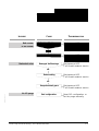
C - Operation
■
Start-up of the M3 monitoring system............................
C 10
■
Setting the M3 monitoring system parameters ................
C 20
■
M3 Monitoring system function table............................
C 30
■
Use of the M3 monitoring system ................................
C 40
■
Use of the M1 monitoring system ................................
C 50
■
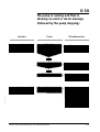
Safety instructions related to maintenance .....................
D 00
■
First level of maintenance...........................................
D 10
■
Maintenance frequency .............................................
D 20
■
Diagnosis and troubleshooting ....................................
D 30
■
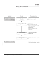
Pump does not start ..................................................
D 40
■
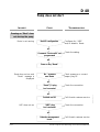
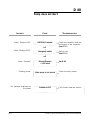
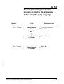
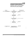
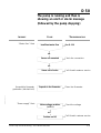
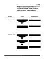
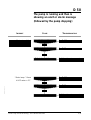
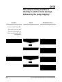
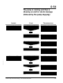
The pump is running and then is showing
2/3
an alert or alarm message (followed by pump stopping) .
D 50
■
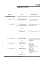
Pump is running - No message ..................................
D 60
■
«Breaker …» Alarm ..................................................
D 70
■
«Pressure»/«Purge N2» Alert and alarm .......................
D 80
■
«Gas temp.» Alert ..................................................
D 90
■
«Pump temp.» Alert .................................................
D 91
■
«Consumption» Alert and alarm ................................
D 100
■
«Water flow» Alert .................................................
D 110
■
«Motor temp.» Alert or alarm....................................
D 120
■
«Analogic input» Alert or alarm.................................
D 130
■
«E1 logic»/«E2 logic» Alert or alarm ........................
D 140
■
«Valve option» Alert and alarm ................................
D 150
■
«Variator» Alarm.....................................................
D 160
Alcatel - High Vacuum Technology - User’s Manual ADP/ADS
Edition 04 - May 98
D - Maintenance
Contents
ADP/ADS
User’s manual
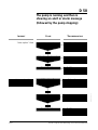
E - Maintenance
instructions
■
Maintenance precautions (Service centers) ....................
E 10
■
Pump draining .........................................................
E 20
■
Silencer maintenance ................................................
E 30
■
Electropneumatic valve maintenance (withdrawal) ...........
E 40
■
Freeing up the ADP ..................................................
E 50
Safety instructions concerning product installation, operation and
maintenance.
Our ALCATEL products are designed and tested to provide
maximum safety. However, in order to obtain the best level of
safety, the following must be observed:
- the user’s manual during product transport, installation, operation
and maintenance.
- the safety instructions signalled with the following symbol:
Symbol
Meaning
Edition 04 - May 98
Users of this equipment should be alert to level of
hazards identified by this symbol.
Warnings are used when failure to observe instructions
or precautions could result in significant damage to
equipment, and/or in injury to humans.
Alcatel - High Vacuum Technology - User’s Manual ADP/ADS
3/3
ADP/ADS Series One dry pumps
Dear Customer,
you have just purchased an
Alcatel dry pump. We thank
you and are proud to include
you in our customers.
This product has benefited
from Alcatel’s many years of
experience in “semiconductor”
processes and dry pumping.
For optimum performance
and to obtain full satisfaction
from this equipment, we
recommend that you study
this manual before any
intervention on your pump,
in particular, the chapter on
installation and start up.
MANUAL REFERENCE : 100 448
EDITION : 04 - May 1998
APPLICATIONS :
• ALL “SEMICONDUCTORS” PROCESSES
Stripping, Etching, PECVD, LPCVD, MOCVD, Epitaxy, …
• SCIENTIFIC RESEARCH
ADVANTAGES :
Easily adaptable to processes - Tested design - Vertical pumping Clean room compatible - Advanced monitoring system functions Low noise level - Low operating cost - Easy maintenance and
repairs - Anti-vibration frame - Compact.
SPECIAL FEATURES :
Multi-stage Roots technology - water-cooled multi-voltage motors built-in monitoring system (remote optional) - anti-dust,
sound-proof aesthetic covers, easily removed - incorporated
purge line (N2) - Quick connection - Modular design and
interchangeable parts - Easy to transport - Network compatible.
Alcatel - High Vacuum Technology - User’s Manual ADP/ADS
1/1
A 10
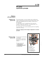
ADP/ADS Series One
Multi-stage pump with
Roots technology
Sealed motor with liquid
cooling
Edition 03 - May 97
Genuinely dry pump
- well-known technology
- reliability
-
no fan (clean room compatible)
safe : no gas leak
quiet
multi-voltage, bi-frequency 50/60 Hz
- guaranteed by design
- guaranteed by testing
Residual gas spectrum free from hydrocarbon peaks
Vertical pumping
Reliability
Easy maintenance
Pump designed for all
processes
2 versions
MTBF > 50 000 hours
- interchangeables parts
- may be performed by user
- Several equipments are available for semi-conductor’s
applications, corrosives, CVD or clean processes
Standard or modular
Alcatel - High Vacuum Technology - User’s Manual ADP/ADS
1/1
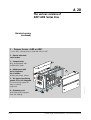
A 20
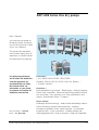
The various versions of
ADP/ADS Series One
Standard version
The Standard Series pumps are fully integrated in a compact and
covered frame which includes: the monitoring system,the flowmeter
panel, the facilities panel, an OEM interface panel and the RS
232/485 serial link.
FRONT VIEW
Inlet port
Monitoring
system
Flowmeter panel
Edition 03 - May 97
REAR VIEW
IN OUT
RS 232/485
Utilities panel
OEM Interface (option)
Exhaust port
Alcatel - High Vacuum Technology - User’s Manual ADP/ADS
1/3
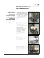
A 20
The various versions of
ADP/ADS Series One
Standard version
(continued)
1 - PUMPING SYSTEMS : ADP or ADS*
* In an ADS, a Roots pump is combined with an ADP.
2 - Silencer with check
valve function
3 - Compact frame
May be equipped with
anti-vibration pads.
4 - Utilities panel with
Quick Connectors
for all utilities :
Water, gas purge, power.
1
5
2
6
3
6 - Flowmeter panel
with water and purge gas
flow rate settings.
2/3
Alcatel - High Vacuum Technology - User’s Manual ADP/ADS
Edition 03 - May 97
5 - Two types of monitoring
system : M1 or M3 integrated
The monitoring system M1
may be remote
(optional).
4
A 20
The various versions of
ADP/ADS Series One
Modular Version
For specific uses,
Alcatel has developped
a modular version from
the series One
which offers in addition
of standard version
the following characteritics
• Footprint and volume minima
• Total flexibility of use due to its
modular possibilities of installation
• No cover for easy integration
• Guaranteed accessibility for
preventive maintenance and
repair.
The “MD” Series is composed
of a pumping unit on its frame
and various modules :
• Flowmeter panel (gas purge
and cooling water)
• Utilities panel (gas purge
and cooling connections)
• Electrical box including
monitoring (M1 or M3)
• OEM interface panel /
Remote control
Edition 03 - May 97
By design, these modules can
be fitted to the pump frame
in the best suitable position
chosen by the user.
Apart from its mounting in the
different possible positions on the
pump frame, the electrical box
can be set remote to 5 meters
from the pump if necessary.
Alcatel - High Vacuum Technology - User’s Manual ADP/ADS
3/3
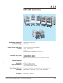
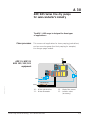
A 30
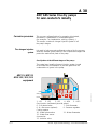
ADP/ADS Series One dry pumps
for semi-conductor’s industry
The ADP / ADS range is designed for three types
of applications :
Clean processes
This concerns all applications for clean pumping (particle-free)
and non-corrosive gases (load lock pumping for example).
No nitrogen purge needed.
Inlet
ADP 31/ADP 81
ADS 151/301/501
equipment
13
Motor
Motor
10
12
11
Water
Anti-suckback valve
Edition 04 - May 98
Exhaust
Silencer
10 - Water electrovalve
11 - Water flowmeter
Alcatel - High Vacuum Technology - User’s Manual ADP/ADS
12 - Water flow sensor
13 - Isolation valve
(accessory)
1/3
A 30
ADP/ADS Series One dry pumps
for semi-conductor’s industry
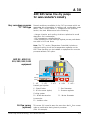
Corrosive processes
The nitrogen injection
system
This concerns all applications for pumping chlorinated,
fluorinated, crystallizable or condensable gases,
(for example : ion implantation, etching, epitaxy...).
This version contains a nitrogen injection system in all
the pump’s stages.
It is used to help evacuate pollutants produced by the process,
dilute the harmful gases present in the compression stages and
protect the mechanical parts of the pump.
Gas injection at the different stages of the pump :
The neutral gas (usually nitrogen) injection system is used
to decrease the concentration of process gases and the
condensation of gases in the pump.
Inlet
ADP 31/ADP 81
ADS 151/301/501
equipment
13
12
11
5
Neutral gas
3
2
1
6
9
Anti-suckback valve
Exhaust
4
7
8
Silencer
1 - LP1
2 - LP2
3 - LP3
4 - HP4
Gas injection (calibrated jets with valves)
5 - HP5 :
6 - Gas electrovalve
8 - N2 flow sensor (optional)
7 - Gas flowmeter
9 - Pressure regulator
Cooling system:
10 - Water electrovalve
12 - Water flow sensor
11 - Water flowmeter
Accessories:
13 - Isolation valve
2/3
Alcatel - High Vacuum Technology - User’s Manual ADP/ADS
Edition 04 - May 98
10
Water
A 30
ADP/ADS Series One dry pumps
for semi-conductor’s industry
Very corrosives processes
“TC“ CVD type
Several models are available for the CVD processes which are
generating lots of quantities of particles and condensable gases
(BPSG, TEOS, LPCVD nitride…). Compared to the previous
version, the main differences are the following:
- nitrogen injection and cooling circuit are optimized to avoid
deposition and condensation.
- ADP temperature controlled device.
- extra protections of ball bearings against process particulates
are used in ADP and Roots.
Note : The ”TC” version (Temperature Controlled) includes an
optimized cooling circuit and a temperature regulation on the
ADP. These functions can be installed on equipment for corrosive
processes without CVD option.
Inlet
ADP 81/ ADS 151/
301/501/801/1001
equipment
12
11
10
Water
Neutral gas
Exhaust
5
3
2
1
6
9
Anti-suckback valve
7
Silencer
1 - LP1
2 - LP2
Neutral gas injection
Edition 04 - May 98
4
10
3 - LP3
4 - HP4
8
5 - HP5 :
6 - Shut-off valve
8 - N2 flow sensor (option)
7 - Gas flowmeter
9 - Pressure regulator
Cooling system:
10 - Water electrovalve
11 - Water flowmeter
Accessories:
12 - Isolation valve
N2 flow sensor
(optional)
This sensor (8) is used to warn the user when the N2 flow comes
under a preset value during harsch processes
(SiH4 for example).
Alcatel - High Vacuum Technology - User’s Manual ADP/ADS
3/3
A 40
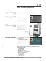
Types of monitoring systems
2 types of monitoring
system
Monitoring system M1
M1 Remote monitoring
system
M1 Solid-state monitoring without neutral gas control,
M3 monitoring driven by a microprocessor .
Parameters monitored :
• Water flow failure
• Electrical overloading
Monitoring system M1 can
be remote controlled.
This is a unit separated
from the frame (5 or
10 meters cable) for the
remote control and
monitoring of the pump.
5 or 10 meters
Edition 04 - May 98
Monitoring system M3
• Monitoring system controlled
by microprocessor
• LCD display of parameters
and messages
• Memorization of the 10
latest alerts and alarms
• RS 232 - RS 485 NETWORK links
This monitoring system can
directly be interfaced with most of the production equipments.
Parameters monitored :
• Water flow failure
• Purge flow failure
• Electrical overloading
• Purge flow and exhaust pressure
• Exhaust gas temperature
• ADP motor power
• Water flow rate
• Maintenance Time
Alcatel - High Vacuum Technology - User’s Manual ADP/ADS
1/1
A 50
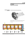
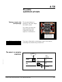
Dry pump
operational principle
Multi-stage Roots
principle
The ADP pump consists of 5 Roots type stages.
The two rotors rotate without touching each other.
The three stages on the low pressure side are called “LP stages”
and the two stages on the high pressure side are called
“HP stages”.
Edition 03 - May 97
Inlet
Water
Silencer
Exhaust
Stage 1
(LP1)
Stage 2
(LP2)
Stage 3
(LP3)
Alcatel - High Vacuum Technology - User’s Manual ADP/ADS
Stage 4
(HP4)
Stage 5
(HP5)
1/3
A 50
Dry pump
operational principle
Tightness
with environment
Tightness at low
pressure side
The pump bearings on the low pressure side are fitted with
ceramic ball bearings lubricated with fluorinated grease which
resists high temperatures and the possible corrosion due to
the application.
An overpressure zone is created around the bearing by
injecting a neutral gas (Purge LP1). The grease works in a
less severe vacuum and thus lasts longer.
This pressurization also prevents pumped gases from migrating
towards the bearings.
Neutral gas purging for the bearings is imperative for corrosive
processes.
3
7
6
The bearings are lubricated by
oil splashing.
The oil sump is sealed from
stage HP5 by a trap and a
deflector.
This trap is also used :
- as a heat barrier
- as a pumped gas barrier
- to recover fluid
2/3
2
5
1
4
1
2
3
4
5
6
7
-
Stage HP5
Trap
Water cooling
HP5 purge
Dynamic seal
Lubrication disk
Gear casing
Alcatel - High Vacuum Technology - User’s Manual ADP/ADS
Edition 03 - May 97
Tightness at high
pressure side
A 50
Dry pump
operational principle
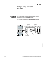
Tightness at motor side
(shaft passage)
The vacuum tightness is
ensured by the motor design
with built-in jacket.
2
This system provides total
safety regarding leaks
outside the pump and
requires no maintenance.
3
1
1 - Built-in jacket
2 - Motor housing
3 - Electrical rotor
Tightness at shutdown
The pump is fitted with a antisuckback valve in the silencer,
preventing the exhaust being sucked back.
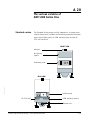
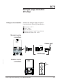
The pump in a pumping
installation
Process
chamber
ADP
pump
SECONDARY
VACUUM
PRIMARY
VACUUM
Secondary
pumping
ATMOSPHERE
Edition 03 - May 97
INLET
PRESSURE
Alcatel - High Vacuum Technology - User’s Manual ADP/ADS
ATMOSPHERIC
PRESSURE
3/3
A 60
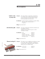
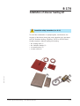
The accessories
Isolation valve
at pump inlet
Principle :
This valve avoids a reverse flow of particles to
the chamber and increases tightness when the
pump is switched off. It allows also to isolate
the running pump from the process.
Part Number : Several models are available in Alcatel catalog
(Manual valve, electropneumatic...).
Consult us.
Fitting : See section B 90
Anti-vibration pads
Principle :
This device significantly reduces the vibration rate
transmitted to the floor.
Vibration force to the floor by pad: < 0,5N Available till 150Hz.
Part Number : ADP . . . . . . . . . . . . . .101838
ADP MD . . . . . . . . . . .101942
ADS 151/301/501 . . .101840
ADS 151/301/501 MD 101941
ADS 801/1001 . . . . . .102136
Fitting : See section B 30
Edition 04 - January 98
Silencer heating kit
Principle :
This device is to be installed on the silencer in order
to avoid the gases condensation, particularly in
processes such as Aluminum etching, Polysilicon
etching, LPCVD or PECVD Nitrid.
Part Number : 110/115 V . . . . . . . . .105038
220/240 V . . . . . . . . .105037
Fitting : See section B 170
Alcatel - High Vacuum Technology - User’s Manual ADP/ADS
1/1
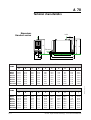
A 70
( Modifications reserved )
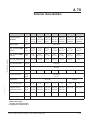
Technical characteristics
Characteristics
Units
Nominal flow-rate
(50/60 Hz)
m3/h
l/mn
cfm
25/30
68/80
140/165 270/310 460/510
680/750
950/1000
418/501 1136/1336 2338/2756 4509/5177 7682/8517 11356/12525 15835/16670
15/18
40/47
82/97
160/182 271/300
400/442
560/589
Rotation speed
rpm
3000/3600
Ultim. pressure* (50 Hz)
maximale
mbar
torr
4.10-2
3.10-2
Ultim. pressure* (60Hz)
maximale
mbar
torr
1.10-2
7 x 10⁻³
Max. cont. inlet pressure mbar/torr 1000/750
ADP 81
ADS 151
4.10-2
3.10-2
4.10-3
3.10-3
9.10-3
9.10-4
-3
6.7 x 10 6.7 x 10⁻⁴
50/38
40/30
ADS 301
ADS 501
3.10-3
3.10-3
2.2 x 10⁻³ 2.2 x 10⁻³
30/23
20/15
10/7,5
5/4
3
5.2
5.2
volt
200/480
Motor power (total)
kW
N2 flow rate range
sccm
Nl/mn
Gear box fluid capac.
Weight std version
Weight mod. version
kg/lb
kg/lb
Ø Inlet/Exhaust portt
DN
Average noise level
dBA
3
0 to 90000
0 to 90
30 to 100
l/h
l
2.10-3
1.5 x 10⁻³
6.10-4
4.5 x 10⁻⁴
Supply voltage 3Ph.
3
2.10-3
1.5 x 10⁻³
6.10-4
4.5 x 10⁻⁴
1200/900
1,5
ADS 1001
8.10-4
6 x 10⁻⁴
mbar/torr
1,5
ADS 801
8.10-4
6 x 10⁻⁴
Max. exhaust pressure
Water flow**
Edition 04 - May 98
ADP31
0.35
0.35
160/353 240/529
130/287 210/463
40/40
40 to 60
0.75
1.1
1.1
3.10
3.1
340/748
280/622
365/805
310/683
380/844
340/748
550/1212
-
620/1377
-
63/40
63/40
100/40
100/40
160/40
40/40
< 70
* Without nitrogen supply
** According to processes (see B120)
See pumping curves at the chapter G
Alcatel - High Vacuum Technology - User’s Manual ADP/ADS
1/3
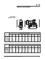
A 70
Technical characteristics
Dimensions
Standard version
Inlet
G
H
F
E
ASPIRATION
Exhaust
REFOULEMENT
95
I
J
D
B
A
C
DIMENSIONS IN MILLIMETERS
ADP
ADP
ADS
ADS
ADS
ADS
ADS
31
81
151
301
501
801
1001
A
B
C
D
E
F
G
H
I
J
1027
1177
1177
1177
1177
1368
1510
975
1125
1125
1125
1125
1331
1445
340
340
398
398
398
398
398
170
170
199
199
199
199
199
680
680
875
875
875
960
1050
650
650
830
830
830
913
945
350
375
520
520
520
650
720
711
711
909
909
909
995
1050
250
250
278
278
278
278
278
884
1034
1040
1040
1040
1230
1360
DIMENSIONS IN INCHES
PUMP
ADP
ADP
ADS
ADS
ADS
ADS
ADS
2/3
31
81
151
301
501
801
1001
A
B
C
D
E
F
G
H
I
J
40.4
46.3
46.3
46.3
46.3
53.8
59.4
38.4
44.3
44.3
44.3
44.3
52.4
56.8
13.4
13.4
15.7
15.7
15.7
15.7
15.7
6.7
6.7
7.8
7.8
7.8
7.8
7.8
26.8
26.8
34.4
34.4
34.4
37.8
41.3
25.6
25.6
32.7
32.7
32.7
35.9
37.2
13.8
14.8
20.5
20.5
20.5
25.6
28.3
28.0
28.0
35.8
35.8
35.8
39.2
41.3
9.8
9.8
10.9
10.9
10.9
10.9
10.9
22.5
26.0
26.0
26.0
26.0
31.2
34.5
Alcatel - High Vacuum Technology - User’s Manual ADP/ADS
Edition 04 - May 98
PUMP
A 70
Technical characteristics
Dimensions
Modular version
INLET
INLET
200
F
G
B
A
45
EXHAUST
J
C
E
15
H
D
I
DIMENSIONS IN MILLIMETERS
PUMP
Edition 04 - May 98
ADP
ADP
ADS
ADS
ADS
31MD
81MD
151MD
301MD
501MD
A
B
C
D
E
F
G
H
I
J
557
557
733
805
805
794
861
861
290
290
290
290
290
160
160
160
160
160
320
320
320
320
320
710
710
710
710
710
400
400
400
400
400
135
135
135
135
135
730
840
840
840
840
223
223
223
223
223
DIMENSIONS IN INCHES
PUMP
ADP
ADP
ADS
ADS
ADS
31MD
81MD
151MD
301MD
501MD
A
B
C
D
E
F
G
H
I
J
21.9
21.9
28.8
31.7
31.7
31.2
33.9
33.9
11.4
11.4
11.4
11.4
11.4
6.3
6.3
6.3
6.3
6.3
12.6
12.6
12.6
12.6
12.6
27.9
27.9
27.9
27.9
27.9
15.7
15.7
15.7
15.7
15.7
5.3
5.3
5.3
5.3
5.3
28.7
33.1
33.1
33.1
33.1
8.8
8.8
8.8
8.8
8.8
Alcatel - High Vacuum Technology - User’s Manual ADP/ADS
3/3
B 00
Safety instructions
• The machines must be connected to an electrical installation in
compliance with the decree 88-1056 dated 14 Novembre 1988.
• Our products are designed to comply with current EEC
regulations. Any modification of the product made by the user is
liable to lead non-compliance with the regulations, or even to put
into doubt the EMC (ElectroMagnetic Compatibility) performance
and the safety of the product. ALCATEL declines any
responsability for such operations.
• Before any maintenance operation is perfomed by a
maintenance technician who has not received safety training
(EMC, electrical safety, chemical pollution, etc.), isolate the
product from the various energy sources (electricity, compressed
air, etc.).
• The EMC perfomance of the product is obtained on the
condition that the installation complies with the EMC rules.
In particular, in disturbed environments, it is essential to:
- use shielded cables and connections for interfaces,
- stabilize the power supply line with meshing from the
power supply source to a distance of 3m from the product inlet.
Edition 03 - May 97
• When the main switch is set to “0“, a part of the equipment
remains energized. Live circuits are exposed and accidental
contact is possible (Energized electrical Work “Hot Work“ in
compliance with SEMI S2-93 Type 4). Before any maintenance
operation, disconnect the main electrical cable.
Risk of electrical shock
Alcatel - High Vacuum Technology - User’s Manual ADP/ADS
Switch off the pump and
disconnect the main cable.
Do not operate inside if your
are not trained and
authorized
1/2
B 00
Safety instructions
• The EMO device is a pump EMO, not a system EMO, so it shuts
only this part of the equipment. To allow the pump to start, turn the
EMO button clockwise and pull it. To control the system EMO, it is
necessary to wire the corresponding contacts on the "Emergency" plug
(see B 140). Either, you can stop the pump from the system EMO by
wiring the terminals on "Remote" connector (see B 140).
• Units containing control circuits are designed to guarantee normal
safety conditions taking into account their usual operating environment
(use in cabinet). In specific cases of use on a table, take care not to
insert objects in the ventilation louvers when handling units.
• When switching off an item of equipment containing capacitors
loaded with over 60VDC or 25 VAC, take precautions at the access to
the connector pins (single-phase motors, fitting with mains filter,
frequency converter, monitoring system, etc.).
• The machines are designed so as to prevent any thermal risk to the
user's safety. However, specific operating conditions may generate on
the pump, temperatures justifying particular attention on the part of the
user (external surfaces > 70°C). Hot surfaces which can cause serious
burns when touched are signalled with specific label.
Hot surface near the label
(pump body, silencer...)
• Alcatel has no control over the types of gases passing through this
pump. These are entirely under the control of the process user and/or
the hardware systems integrator. Frequently, process gases are toxic,
flammable, corrosive, explosive an otherwise reactive. Since these
gases can cause serious injury or death, it is very important to plumb
the exhaust of the pump to the facility's hazardous gas exhaust system
which incorporates appropriate filters, scrubbers, etc., to insure that
the exhaust meets all air and water pollution control regulations.
• The enclosures have to be exhausted with a volumetric flow rate of
86 CFM, with a duct static pressure of 0.35” w.g. (as measured 2.0’
from the duct connection to the cabinet). The size of the exhaust duct
is 4”, the material can be PVC, except for flammable gases for wich
stainless steel is strongly advised.
2/2
Alcatel - High Vacuum Technology - User’s Manual ADP/ADS
Edition 03 - May 97
Hot surface
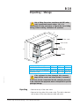
B 10
Unpacking / Storage
Risk of tilting: Even when compliance with EEC safety
rules is guaranted (normal range ± 10°), it is
recommended to take precautions as regards the risk of tilting
during product handling, installation and operation.
C
A
Outer crate
Inner crate
B
Pump
(Standard)
Palett
mm ± 50 (inch ± 2)
B
C
A
ADP 31/81 SD and MD
1350 (53) 500 (38) 980 (19.7)
ADS 151/301/601 St and MD 1350 (53) 1150 (45) 520 (20.1)
ADS 801/1001
1900 (74.6) 1520 (58) 810 (32)
Edition 03 - May 97
If the equipment has been damaged, take necessary
steps with the carrier and inform Alcatel, if necessary.
In all cases, Alcatel recommends that the packaging be saved,
in the event that the equipment must be transported or put into
prolonged storage.
Unpacking
• Remove the top of the outer crate.
• Remove the long side of the outer crate. This side is attached
with screws; all the other sides are held with nails.
Alcatel - High Vacuum Technology - User’s Manual ADP/ADS
1/2
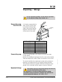
B 10
Unpacking / Storage
For all equipment handling, use the devices provided
for this purpose (lifting rings, handle, etc.) .
Prepare the pump
It is highly recommended to
used a hoist. Lift the pump
by its three hoisting rings.
Apply just enough upward
tension to take the weight
off the base of the pump.
Hook
90°
maxi
Pump Type
Weight in Ibs/(kg)
ADP 31
ADP 81
ADS 151
ADS 301
ADS 501
ADS 801
ADS 1001
353 (160)
529 (240)
748 (340)
805 (365)
844 (380)
1212 (550)
1377 (620)
Hoisting
ring
Screw the leveling pads of the frame and lower the pump
on the wheels.
Remove any additional packages from the crate and set aside.
These packages will contain cables, accessories, and so forth.
To prevent humidity from entering the pump during transport,
the pump is pressurized with dry nitrogen before shipment.
The inlet and exhaust are sealed with blank-off flanges which
should not be removed until the pump is ready to be used.
Equipment storage
2/2
If the pump is going to be put into storage, the inlet and
exhaust, seals should be left in place.
Our equipment can be stored without particular storage
precautions (pump pressurized in nitrogen and sealed) at an
ambient temperature between -20°C and + 70°C.
Alcatel - High Vacuum Technology - User’s Manual ADP/ADS
Edition 03 - May 97
Remove the pump
from the crate
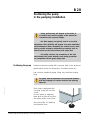
B 20
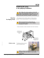
Positioning the pump
in the pumping installation
• Pump performance will depend on the kinds of
accessories used and the quality of the mechanical
connections such as pump fittings.
• As these pumps are typically used in a corrosive
atmosphere, their reliability will depend on proper installation
and maintenance. When assembling the vacuum circuit, make
sure to provide necessary maintenance accessories such as
shut-off valves on the inlet, exhaust, and purge lines.
• For safety reasons, use accessories on the inlet
and exhaust lines whose materials and sealing properties
are compatible with the gases being used.
Positioning the pump
Determine where the pump will be placed. Refer to the technical
specifications section for dimensions, if needed (section A).
Use a hoist to handle the pump, lifting it by the three hoisting
rings.
Edition 03 - May 97
The pump must be operated in the horizontal position,
with the pumping axis vertical and the inlet opening
upwards.
Each pump is equipped with
a locking screw jack on each
corner.
Lock the pump by adjusting
these jacks so that all four feet
are resting solidly on the floor.
See section B30 for installing
Anti-vibration Pads.
Alcatel - High Vacuum Technology - User’s Manual ADP/ADS
1/3
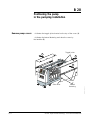
B 20
Positioning the pump
in the pumping installation
Remove pump covers
• Unfasten the toggle joints located on the top of the cover (1).
• Unfasten the lateral fastening and raise the cover by
the handles (2).
Toggle joints
2
1
1
2
Side cover
2/3
Lateral
fastening
Alcatel - High Vacuum Technology - User’s Manual ADP/ADS
Edition 03 - May 97
Handle
B 20
Positioning the pump
in the pumping installation
Risk of tilting: Even when compliance with the EEC
safety rules is guaranteed (normal range ± 10°), it is
recommended to take precautions as regards of the risk of
tilting during product handling, installation and operation.
Removing
the shipping braces
• The shipping braces hold the pump to the frame during
shipment. They are painted yellow, for easy identification.
Release the pump(s) from the frame before use.
Keep the flanging components in order to dispatch
the equipment, if required.
• Remove these bars and the threaded rods which hold them.
Securing nut
Transversal bar
Screw
Edition 03 - May 97
Securing nut
Transversal bar
Threaded rod
Modular version
The shipping braces are also
used as hoisting device.
Failure to remove the shipping braces could later cause
the pump to seize as a result of a strain exerted
by the braces.
Alcatel - High Vacuum Technology - User’s Manual ADP/ADS
3/3
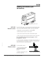
B 30
Installing anti-vibration pads
(Accessories)
Anti-vibration pads
ADP/ADS
Standard version
The ADP/ADS pumps can be equipped with anti-vibration pads
which are mounted beneath the pump, near the locking feet.
• Remove the covers as described in section B 20.
• Raise the pump using the 4 screws jacks.
• Screw into the previous holes the 4 anti-vibration pads.
• Screw the screw jacks so that the machine rests on the pads.
Force transmitted to the ground by each support: < 0.5 N
for frequencies ≤ 150 Hz.
Edition 03 - May 97
In order to limit the transmission of vibrations along the pipes, it
is recommended to use «flexible» connection accessories at the
inlet and exhaust side (expanding type).
ADP/ADS
Modular version
On the modular version :
• Screw the delivered angle
into the frame holes after
removing the shipping
braces.
•Install the anti-vibration pads
(as shown opposite).
Alcatel - High Vacuum Technology - User’s Manual ADP/ADS
1/1
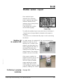
B 40
Modular version - Layout
Main modules layout
(electrical box, flowmeter
panel, water and gas utilities,
customer interface) fit the
customer choice among factory
set configurations.
Other layouts are possible,
see the following page.
Sensor box
To modify the modules layout, some rules have to be followed :
- Pump(s) cannot change its(their) orientation with respect to
the frame.
- The sensor box, located under the pump, has to be set facing
the silencer.
Stabilizer kit
for modular ADS
For safety reasons, the modular ADS are now equipped with a
stabilizer to avoid any risk of
toppling over. It consists of two
supports, one either side of the
frame, equipped with rollers at
the bottom.They slide into a
housing and are bolted into place
during transport. The housing is
bolted to one end of the frame.
Edition 03 - May 97
When pump is installed, the
supports are stored, legs up, and
fixed by means of two bolts.
This kit is a part of modular
pumps marked with a serial
number upper than 973187.
It can be fitted to retrofit on older
pumps by ordering P/N 104527.
Positioning in pumping
installation
See page B 20.
Alcatel - High Vacuum Technology - User’s Manual ADP/ADS
1/2
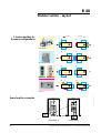
B 40
Modular version - Layout
5 basics modules for
8 pumps configurations
Exhaust
Exhaust
E
A
Inlet
Inlet
Pump block with frame
F
B
Inlet
Inlet
Control box with integrated monitor
G
C
Inlet
Inlet
OEM interface
Utilities panel
H
D
Inlet
Inlet
Some location examples
EXHAUST
POWER SUPPLY
EXHAUST
WATER & N2
SUPPLIES
WATER & N2
SUPPLIES
POWER SUPPLY
MOTOR
INLET
MOTOR
CONTROL
BOX
FLOWMETER
PANEL
CONFIGURATION A
2/2
CONTROL
BOX
CONFIGURATION F
Alcatel - High Vacuum Technology - User’s Manual ADP/ADS
Edition 03 - May 97
Flowmeter panel
B 50
Filling the machine oil housings
Caution ! The pumps are delivered without an oil charge:
the oil is found in separate containers. Similarly, it is
recommended to drain the pump before redispatching the
equipment.
For machines wich use lubricants, it is recommended to
request the manufacturer for the safety data sheets
concerning the product used.
The pump is tested using synthetic fluid Alcatel 113.
When pumping corrosive gases, we recommend synthetic fluid
Alcatel 113.
Mineral and synthetic oils cannot be used together.
Contact Alcatel or your service agent before making
any changes.
Oil quantities
OIL
FILLING
:
Edition 04 - May 98
HOUSINGS :
ADP 31/81
ADS 151
ADS 301
ADS 501
ADS 801
ADS 1001
Filling procedure
ADP
0.35
“
“
“
"
"
REAR
ROOTS
FRONT
ROOTS
HOUSING
HOUSING
TOTAL
CAPACITY
L
0.25
0.45
0.45
1.95
1.95
L
L
L
L
L
0.15
0.25
0.25
0.80
0.80
L
L
L
L
L
0.35
0.75
1.05
1.05
3.10
3.10
L
L
L
L
L
L
- Proceed to oil filling when the pump is stopped.
- Remove the fill cap.
- Fill the pump with oil.
Do not exceed the indicated quantities.
The oil level should be in the middle of the sight glass.
For this to be accurate, wait a few minutes for the oil
to settle over all internal surfaces.
Replace the fill cap.
(See location page 2)
Alcatel - High Vacuum Technology - User’s Manual ADP/ADS
1/2
B 50
Filling the machine oil housings
Location
1
2
3
4
5
1 - Filling front Roots housing
6
2 - Front Roots housing level
sight glass
4 - ADP housing oil level sight
glass
5 - Rear Roots housing filling
6 - Roots housing oil level sight
glass
2/2
Alcatel - High Vacuum Technology - User’s Manual ADP/ADS
Edition 04 - May 98
3 - ADP filling
B 60
Connection to the cooling circuit
Water characteristics
In order to limit corrosion and fouling of the motor cooling coils,
it is recommended to use cooling water with the following
characteristics :
■
■
■
■
■
■
■
■
Treated fresh water or non-aggressive industrial water
pH between 7.5 and 11
Hardness < 7 milli-equivalent/dm3
Resistivity > 1500 Ω.cm
Solid pollution < 100 mg/dm3
Temp. from 10° to 25°C
Pressure range between 3 and 7 bars absolutes
Pressure ∆ inlet/outlet 3 bars mimimum
If the above mentioned characteristics are not respected, install
a filter to the cooling connection.
Edition 03 - May 97
Standard version
connections
REAR
VIEW
IN OUT
1/4 NPT
1/4 NPT
1/4 Gas
1/4 Gas
ALCATEL supply
Alcatel - High Vacuum Technology - User’s Manual ADP/ADS
1/2
B 60
Connection to the cooling circuit
Modular version
connections
REAR
VIEW
N2
OUT
N2
OUT
IN
IN
Waterflowrate
adjustment
}
Water
IN/OUT
N2 FLOW
Flowmeter panel
PRESSURE
WATER
FLOW
Needle tap
The water flow will be adjusted according to the processes with
the needle tap (see section B120).
2/2
Alcatel - High Vacuum Technology - User’s Manual ADP/ADS
Edition 03 - May 97
Waterflowrate
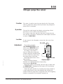
B 70
Inert gas purge connection
(N2 plug)
Nitrogen characteristics
A filtered dry nitrogen supply is required.
It should have the following characteristics :
■
■
■
■
■
Dew point < 22° C
Dust < 1µ.m
Oil < 0,1 PPM
Pressure between 3 and 7 bar absolute.
Flowrate per pump: 100 l/min.
Standard version
connections
REAR
FACE
Customer supply
4 mm
6 mm
1/8 Gas
IN OUT
1/8 Gas
Edition 04 - May 98
ALCATEL supply
Modular version
connections
REAR
FACE
N2
}
Gas
OUT
N2
OUT
IN
Alcatel - High Vacuum Technology - User’s Manual ADP/ADS
IN
1/2
B 70
Inert gas purge connection
(N2 plug)
N2 flowrate
adjustment
The N2 flowrate will be adjusted with the pressure regulator
according to the process (see section B 120).
The flowmeter is used to display the overall purge flow rate.
Pressure
gauge
N2 FLOW
PRESSURE
WATER
FLOW
Flowmeter panel
Edition 04 - May 98
Purge gas
flowmeter
Pressure
regulator
2/2
Alcatel - High Vacuum Technology - User’s Manual ADP/ADS
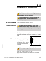
B 80
Nitrogen purge flow sensor
Function
Operation
Location
This sensor is used to warn the user when the N2 flow comes
under a preset value during harsch processes using dangerous
gases (SiH4 for example).
The gas flow rate through the detector carries along a float
which acts on the contact of the electrical box.
This contact closes when the flow rate value is higher than the
flow rate set on the sensor. Otherwise the contact opens and set off
an alarm “PURGE FLOW“.
To get access to the flowmeter, remove the side cover from
the pump.
N2 outlet
Edition 03 - May 97
Adjustment
- First set the parameter
"N2 FLOWRATE OPTION" to be
valid in the "DEFINITION menu
of the M3 monitoring system.
- The setting of the sensor is
0.3
done by sliding the moving part
(contact) along the controller body.
Nl/mn
For this, loosen the screws fixing
N2
this moving part on the body
N2 inlet
- Adjust the electrical box in the
upper position.
Electrical box
- Set the minimum Nitrogen
flowrate to be detected with the corresponding
purge pressure (See B 120).
- Adjust the position of the moving part from top to bottom until
the PURGE FLOW is displayed on the screen of M3 monitoring.
Fix it with the screws.
- Check the good operation by increasing the purge pressure to
a level higher than the one to be detected, then reduce this
pressure until the purge alert is triggered. Note if this triggering
pressure corresponds to the minimum required one.
Alcatel - High Vacuum Technology - User’s Manual ADP/ADS
1/1
B 90
Connection to the pumping circuit
In order to prevent moisture from entering the pump
before its installation, it is pressurized beforehand with
nitrogen and sealed with blank-off flanges.
The vacuum pump is also a compressor: incorrect use
may be dangerous. Study the user manual before
commissioning the pump
At the exhaust pump
Preliminary precautions
First of all, remove the plug at the exhaust.
Provide maintenance accessories, for vacuum circuit
mounting (inlet and exhaust isolation valves, purges, …)
It is recommended to connect the pump exhaust to a flue gas
evacuation pipe.
For safety reasons, use at pump inlet as well as exhaust,
accessories with materials and tightness compatible with pumped
gases.
Edition 03 - May 97
Anti-noise seal
For free exhaust tests (inert gas
pumping), an anti-noise seal
supplied with the pump can be
fitted on to the silencer exhaust
in order to reduce the exhaust
noise level.
Anti-noise seal
Anti-noise seal
delivered separately
When pumping on aggressive gases, the exhaust must
be connected to a stack or an evacuation duct.
In this case, do not fit the anti-noise seal.
Make sure that the pressure at the exhaust does not exceed
1200 mbar.
Alcatel - High Vacuum Technology - User’s Manual ADP/ADS
1/2
B 90
Connection to the pumping circuit
Exhaust connection
At inlet pump
DN40 ISO KF Pneurop.
Several fitting accessories are available in Alcatel catalog.
Make sure that the parts or containments connected to
the inlet of our pumps withstand a negative pressure of
1 bar with reference to the atmospheric pressure.
In order to prevent foreign bodies from entering the pump,
leave the blank-off flange in place at the pump inlet and remove
it at the time of use.
(see section B 130).
This accessory avoids a reverse flow of particles to
the chamber when the pump is stopped.
Connect the valve directly on the pump inlet flange using
connecting accessories.
Connect the valve to the chamber.
Connect the electrical cable to the "inlet valve / exhaust valve"
connector at the rear of the M3 monitoring system.
Edition 03 - May 97
Inlet isolation valve
(accessory)
2/2
Alcatel - High Vacuum Technology - User’s Manual ADP/ADS
B 110
Pump Power supply
Study the preliminary precautions (See B 00)
All the electrical connections required for operation have been
done in the factory.
However, the user must make the electrical connection of
the main power supply, connect the remote monitoring system
options.
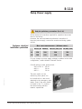
Customer electrical
installation protection
MAIN
CIRCUIT BREAKER RATING
: (Minimum value) :
ADP 31/81 ADP 81V ADS 151/301/501 ADS 801/1001
LV
15A
20A
20A
25A
HV
10A
15A
15A
20A
For any change of power supply voltage in relation to the initial
configuration, contact Alcatel Customer Service.
Edition 04 - May 98
Cutt off rating of main pump switch :
- 200 to 415 V : 50 kA
- 460 V :
20 kA
- 480 V :
10 kA
The main switch on the
monitoring front panel can
be locked with a catch hook
attached to the emergency stop
button. Even if the main switch
is locked in the "1" position,
the disconnecting function
remains operational.
Alcatel - High Vacuum Technology - User’s Manual ADP/ADS
1/3
B 110
Pump Power supply
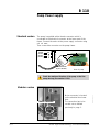
Standard version
The pump is supplied with a female connector which is
connected to the electrical connector at the lower part of the
frame. Connect the mains to the power supply connector using
a 4 x 4 mm2.
Then connect the connector on the pump frame.
Ground
phase 3
phase 2
phase 1
Y/G
Female connector
(6 pins + Ground)
Rear of pump
Check the rotational direction of the pump at the first
pump start-up (See section B 130).
Mains connector
2/3
Mains connector is located
on the electrical box lower
face.
The connection has to be
carried out as defined
previously in page 1.
Alcatel - High Vacuum Technology - User’s Manual ADP/ADS
Edition 04 - May 98
Modular version
B 110
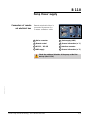
Pump Power supply
Connectors of remote
set electrical box
Remote set electrical box is
connected by means of a
5 meters extension cable.
1
3
2
4
7
8
6
5
1 Mains connector
2 Roots supply (ADS)
3 Remote control
4 Sensors information (n° 1)
5 RS 232 / RS 485
6 Interface connector
7 ADP supply
8 Sensors information (n° 2)
Edition 04 - May 98
Check the rotational direction of the pump at the first
start-up (See B 130).
Alcatel - High Vacuum Technology - User’s Manual ADP/ADS
3/3
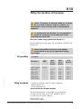
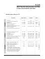
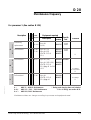
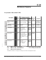
B 120
Water flowrate and gas purge according
to main semiconductor processes
100l/h
non CVD
non CVD
non CVD
No
*20l/mn (0.2 bar)
No
25l/mn (0.3 bar)
25l/mn (0.3 bar)
100l/h
60l/h
60l/h
non CVD
25l/mn (0.3 bar)
60l/h
non CVD
35l/mn (0.6 bar)
40l/h
non CVD
non CVD
non CVD
non CVD
CVD
CVD
35l/mn (0.6 bar)
35l/mn (0.6 bar)
45l/mn (1 bar)
35l/mn (0.6 bar)
50l/mn (1 bar)
50l/mn (1 bar)
60l/h
40l/h
100l/h
60l/h
60l/h
60l/h
CVD
50l/mn (1 bar)
60l/h
CVD
70l/mn (1.5 bar)
40l/h
CVD
CVD
70l/mn (1.5 bar)
90l/mn (2 bar)
40l/h
40l/h
Load lock
If possible chlorine degassing
Sputtering
Dielectric etch
Stripping with plasma O2 trap can be useful
(proposed by some manufacturers)
• Resist and polyamid etch trap can be useful
(proposed by some manufacturers)
• Metal etch - heated piping and
exhaust lines advised
• Poly etch
• Ion implant (source)
• Tungsten LPCVD
• Titanium and Titanium nitride PECVD
• Polysilicon LPCVD and PECVD
• Silicon oxide PECVD and LPCVD
using Silane
• Silicon oxide and doped oxide
(BPSG) PECVD using TEOS
• Silicon oxide and doped oxide
(BPSG) LPCVD using TEOS
• Silicon nitride PECVD
• Silicon nitride LPCVD cold trap at the oulet of the furnace
can be useful - no heating of the line
between the cold trap and the pump.
* Should the layer be thick (>1500A),
please contact Alcatel Worldwide
Technical Support for dry pumps.
Alcatel - High Vacuum Technology - User’s Manual ADP/ADS
P 1 Maintenance
non CVD
•
*
•
•
•
P 2 Maintenance
Water
P 3 Maintenance
Nitrogen
PROCESSES 1
Pump version
PROCESSES 2
Processes
PROCESSES 3
Edition 04 - May 98
Standard pump setting (no TC)
1/2
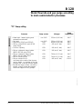
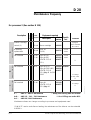
B 120
Water flowrate and gas purge according
to main semiconductor processes
“TC“ Pump setting
• Silicon oxide and doped oxide
(BPSG) PECVD using TEOS
• Silicon oxide and doped oxide
(BPSG) LPCVD using TEOS
• Silicon nitride PECVD
• Silicon nitride LPCVD cold trap at the oulet of the furnace
can be useful - no heating of the line
between the cold trap and the pump.
* Should the layer be thick (>1500A),
please contact Alcatel Worldwide
Technical Support for dry pumps.
Pump version
Nitrogen
Pump
temperature
non CVD
35l/mn (0.6 bar)
90°C
non CVD
CVD
CVD
35l/mn (0.6 bar)
45l/mn (0.8 bar)
50l/mn (1 bar)
80°C
80°C
80°C
CVD
50l/mn (1 bar)
80°C
CVD
50l/mn (1 bar)
90°C
CVD
70l/mn (1.5 bar)
90°C
CVD
CVD
70l/mn (1.5 bar)
90l/mn (2 bar)
90°C
100°C
Edition 04 - May 98
PROCESSES 2
• Metal etch - heated piping and
exhaust lines advised
• Poly etch
• Polysilicon LPCVD and PECVD
• Silicon oxide PECVD and LPCVD
using Silane
• Si mono. Epitaxy
PROCESSES 3
Processes
2/2
Alcatel - High Vacuum Technology - User’s Manual ADP/ADS
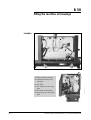
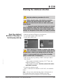
B 130
Checking the rotational direction
Study the preliminary precautions (See B 00)
Before using the pump, check that the connections
defined in the start-up chapter have been made.
Also, make sure that all the oil levels are visible at the center
of the indicator.
• Remove the guards blocking the intake and exhaust
(and, if applicable, purge) holes; these components prevents
foreign bodies from entering the pump during transport and
storage. It is dangerous to leave them on a pump in operation.
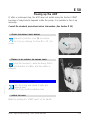
Check the rotational
direction of the pump at
the first pump start-up
• Remove the blank-off flange on the inlet port.
• Fit a pressure gauge at the pump inlet.
• Set the main switch on I.
Edition 03 - May 97
When inspecting the direction of rotation of the Roots
pump at installation, provide protection against the risk
of compression related to the rotating machine on the inlet.
Caution ! A non-powered Roots can be driven by another
pump in rotation (risk of compression) .
• Start up the pump by pressing “START” and stop it after a
few seconds :
- if the pressure indicated is less than 5.10-1 mbar, the
rotational direction is correct.
- if the pressure increases, invert two phases at the mains
input female connector.
• Connect the pumping circuit.
(Note : In the case of an ADS 801 or ADS 1001, do not start the
Roots.)
Note : We can also check that the pump is forcing back at
the exhaust after that the blank-off flanges have been
removed from inlet and exhaust.If not, invert two phases.
Alcatel - High Vacuum Technology - User’s Manual ADP/ADS
1/1
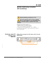
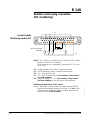
B 140
Remote control plug connection
(M3 monitoring)
Study the preliminary precautions (See B 00)
When units containing control circuits are equipped
with dry contact outputs, it is the responsibility of the
customer to use these outputs in compliance with safety
standards.
Remote control function allows to :
• Remote control of pumping functions
“START/STOP/Emergency stop/PURGE”.
• Copy out with dry contacts (250V - 1A - 100VA)
the monitoring parameters. These contacts can be used to
control automatisms.
Monitoring system M3
Remote control
«REMOTE»
Wiring of the cover plug to put if the remote control is not used
(REMOTE plug).
1
17
18
33
19
41
44
47
50
Edition 03 - May 97
34
Alcatel - High Vacuum Technology - User’s Manual ADP/ADS
1/3
B 140
Remote control plug connection
(M3 monitoring)
0V
Control (Inputs)
Monitoring system M3
17
1
18
19
20
21
22
23
41
34
Wiring customer
supplied
24
33
25
47
44
50
Arrêt d'urgence
Emergency
stop
S1
S2
S3
S4
+12V
NOTE : The contact is considered to be closed if the DC voltage
between 5 and 30 V is applied.
These contacts can be supplied by terminals 47 (OV) and
49 (+12V).
S1
S1
S2
S3
OPEN Remote control valid / Keyboard locked
CLOSE Keyboard valid / Remote control locked
On / ADP switching off
On / ROOTS switching off if the selection “Roots control“
has been validated
S4 : Purge Switching on / off if the selection “Purge control“
has been validated in the help menu with keyboard.
Monitoring system before V2.02 version
Note: If the remote control receives an order from the RS232,
keyboard and remote control are locked. Only LOC order
transmitted by the RS232 allows to enable keyboard or
remote control. (Contact Alcatel)
2/3
Alcatel - High Vacuum Technology - User’s Manual ADP/ADS
Edition 03 - May 97
:
:
:
:
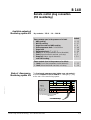
B 140
Remote control plug connection
(M3 monitoring)
Available outputs of
Monitoring system M3
Dry contacts : 250 V - 1 A - 100 VA
Contact
These contacts open in the presence of a fault.
1 - ADP working
2 - ROOTS working
3 - Purge flow rate and ADP working
4 - Exhaust pressure fault : P>1450mbar
5 - Purge fault
6 - Temperature fault : T° > 50° C
4 - Fault (One of the parameters at alert threshold)
5 - Fault (Alarm threshold reached, unit stop)
6 - Pump fail (Alarm signal detected)
and ADP working
These contacts close in the presence of a defect :
1 - Fault (One of the parameters at alert threshold)
2 - Fault (Alarm threshold reached, unit stop)
State of «Emergency»
Monitoring system M3
14 - 15
16 - 17
8-9
39 - 40
37 - 38
35 - 36
2-3
4-5
1 - 34
12 - 13
11 - 10
The front panel emergency stop button copy out contact is
available between 1 and 2 contacts of “emergency“ plug
at the rear of the monitoring system.
OPTION
ROOTS CONT.
LI 2
MOTOR TEMP.
PURGE
VALVE
WATER
VALVE
ANA. INPUT
Edition 03 - May 97
RS 232
REMOTE
LI 3
LI 1
WATER
FLOW
EXHAUST
VALVE
EMERG.
WATTMETER
Prise EMERGENCY
EMERGENCY
Plug
Alcatel - High Vacuum Technology - User’s Manual ADP/ADS
3/3
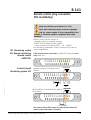
B 141
Remote control plug connection
(M1 monitoring)
Study the preliminary precautions (See B 00)
When units containing control circuits are equipped
with dry contact outputs, it is the responsibility of the
customer to use these outputs in compliance with safety
standards.
M1 Monitoring system
M1 Remote monitoring
Remote control
«REMOTE»
Remote control function allows to :
• Remote control of pumping functions
“START/STOP/Emergency stop/PURGE”.
• Copy out with dry contacts (250V - 1A - 100VA)
the monitoring parameters. These contacts can be used to
control automatisms.
If the remote control is not used, put (REMOTE plug) the cover
plug wired like :
13
12 11 10
25 24
Controls (Input)
Monitoring system M1
8
7
23 22 21 20
6
5
4
25 24
10
23 22
9
8
7
21 20 19
6
5
4
18 17
3
25 24
23 22
8
7
21 20 19
1
15 14
2
1
16 15 14
ON
Marche
Arrêt d'urgence
Emergency
stop
With inhibition of remote control buttons:
With switch :
9
2
Arrêt d'urgence
Emergency
stop
OFF
Arrêt
13 12 11 10
3
18 17 16
19
Without inhibition of remote control
buttons :
13 12 11
Edition 03 - May 97
9
6
5
18 17
4
3
2
1
16 15 14
Interrupteur
ON / OFF MA/AR
switch
The remote control STOP button will stop the ADP, but it will
restart as the push button is released.
Alcatel - High Vacuum Technology - User’s Manual ADP/ADS
1/4
B 141
Remote control plug connection
(M1 monitoring)
Emergency
stop
Arrêt d'urgence
With external power supply :
13 12
25
-
24
11 10
9
8
23 22 21 20
7
6
5
4
19 18 17
3
2
1
16 15 14
+
24V
Dry contacts : 250 V - 1 A - 100 VA
These contacts open in the presence of a fault.
Two contacts available for each fault type.
Available outputs :
State of «Emergency»
Monitoring system M1
Contact 1
Contact 2
1 - Major faults :
RT1 switched off
12 - 13
8 - 21
2 - Pump working :
KM1 switched off
9 - 22
6 - 19
3 - Temperature faults :
T° > 50° C
10 - 11
7 - 20
The front panel emergency stop button copy out contact is
available between 7 and 8 contacts of “emergency“ plug
at the rear of the monitoring system.
WATER
VALVE
MOTOR TEMP.
EMERG
REMOTE
RT1
CB 1
Prise EMERGENCY
EMERGENCY
Plug
2/4
Alcatel - High Vacuum Technology - User’s Manual ADP/ADS
Edition 03 - May 97
Available outputs of
Monitoring system M1
B 141
Remote control plug connection
(M1 monitoring)
M1 Monitoring system
on modular ADP
Remote control
«REMOTE»
If the remote control is not used, put (REMOTE plug) the cover
plug wired like :
1
2
18 19
3
4
5
6
7
8
9
13 14 15 16 17
10 11 12
20 21 22 23 24 25 26 27 28
29 30 31 32 33
34 35 36 37 38 39 40 41 42 43 44 45
Control (Inputs)
Monitoring system M1
Without inhibition of
remote control buttons :
1
2
18 19
3
4
5
46 47 48 49 50
ON
Marche
6
7
8
9
10 11 12
20 21 22 23 24 25 26 27 28
13 14 15 16 17
29 30 31 32 33
34 35 36 37 38 39 40 41 42 43 44 45
46 47 48 49 50
Arrêt d'urgence
Emergency
stop
Arrêt
Stop
Edition 03 - May 97
With inhibition of remote control buttons:
With switch :
1
2
18 19
3
4
5
6
7
8
9
10 11 12
20 21 22 23 24 25 26 27 28
34 35 36 37 38 39 40 41 42 43 44 45
13 14 15 16 17
29 30 31 32 33
46 47 48 49 50
Arrêt d'urgence
Emergency
stop
Interrupteur
ON / OFFMA/AR
switch
The remote control STOP button will stop the ADP, but it will
restart as the push button is released.
Alcatel - High Vacuum Technology - User’s Manual ADP/ADS
3/4
B 141
Remote control plug connection
(M1 monitoring)
With external power supply :
1
2
3
18 19
4
5
6
7
8
9
13 14 15 16 17
10 11 12
20 21 22 23 24 25 26 27 28
29 30 31 32 33
34 35 36 37 38 39 40 41 42 43 44 45
-
+
Arrêt d'urgence
Emergency
stop
24VDC
Dry contacts : 250 V - 1 A - 100 VA
These contacts open in the presence of a fault.
Two contacts available for each fault type.
Available outputs :
State of «Emergency»
Monitoring system M1
Contact 1
Contact 2
1 - Major faults :
RT1 switched off
12 - 13
8 - 21
2 - Pump working :
KM1 switched off
8 - 10
14 - 15
3 - Temperature faults :
T° > 50° C
5-7
35 - 36
The front panel emergency stop button copy out contact is
available between 7 and 8 contacts of “emergency“ plug
at the rear of the monitoring system.
WATER
VALVE
MOTOR TEMP.
EMERG
REMOTE
RT1
CB 1
EMERGENCY
Plug
Prise EMERGENCY
4/4
Alcatel - High Vacuum Technology - User’s Manual ADP/ADS
Edition 03 - May 97
Available outputs of
Monitoring system M1
46 47 48 49 50
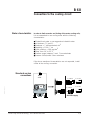
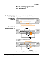
B 150
RS 232 or RS 485 link wiring
At the first power-on, the user will find the initial configuration
set at factory.
The settings can be modified through the M3 corresponding
menu.
The initial configuration of the serial link is as follows:
■ Type : RS 232
■ Transmission SPEED : 9600 bauds
■ Data Length : 8 bits
■ Parity : NONE
■ Stop bit : 1
Connector wiring
RS232/485
(Reception data) (RS 232) RD
TD (Transmission data) (RS 232)
GND (Ground)
1
2
Edition 03 - May 97
6
9-pin male DB connector for
serial link.
Alcatel - High Vacuum Technology - User’s Manual ADP/ADS
3
7
4
8
5
9
V(+) (RS 485)
V(-) (RS 485)
1/2
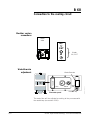
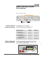
B 150
RS 232 or RS 485 link wiring
Examples of possible
connection
Link RS232
with a single
monitoring system M3
Multiple serial link
RS232
1
1
6
6
5
9
5
9
Several M3 monitoring systems may be connected on a
single link.
The multiple link is obtained by creating a loop:
6
6
9
1
5
6
9
1
5
6
9
1
5
9
1
5
6
1
6
9
5
1
6
9
5
1
9
5
Connect terminals 7 and 8 when the monitoring system is at
the end of the line.
The commands and messages reception syntax is dealt with in
a special chapter (Contact Alcatel).
2/2
Alcatel - High Vacuum Technology - User’s Manual ADP/ADS
Edition 03 - May 97
Serial link RS485
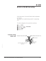
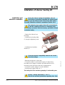
B 170
Installation of silencer heating kit
Consult the safety instructions (see B 00)
To avoid the condensation of pumped gases, and therefore, the
clogging of the silencer during the pump operation wich processes
such as: Aluminum etching, Polysilicon, LPCVD or PECVD Nitrid,
Alcatel proposes a silencer heating kit including:
• two heating belts (1)
• two insulation sleeves (2)
• a connection box (3)
• a mains cable (4).
1
Edition 01 - May 98
2
3
4
Alcatel - High Vacuum Technology - User’s Manual ADP/ADS
1/2
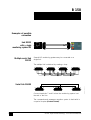
B 170
Installation of silencer heating kit
Installation and
electrical connection
During the silencer heating kit installation, take all
the necessary precautions regarding the pumped gases
before to open the exhaust circuit of the pump. Refer also to
the safety instructions related to maintenance Section D 00.
The electrical power supply of the kit is not monitored
by the M3 controller (in case of an emergency stop,
the belt stays powered). Take the necessary precautions related
to electrical safety.
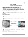
• Remove the silencer from
the pump.
• Install the two heating belts
(1) using the tightening cords.
• Install the two insulation
sleeves (2).
1
2
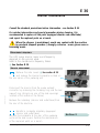
• Remount the silencer on the pump.
• Connect the belts (1) to the power supply (3) after wiring
the cables on the plugs if necessary (provided with the kit or
recovered on the old belts in the case of maintenance).
• Connect the power supply (3) to the installation.
• Set the power supply switch to ”I”.
The heating kit will be used during pumping of condensable gases.
Caution : Heating temperature = 130 °C.
Take all the necessary precautions regarding burn risks.
2/2
Alcatel - High Vacuum Technology - User’s Manual ADP/ADS
Edition 01 - May 98
Check the electrical compatibility between the kit and
the mains voltage.
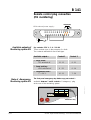
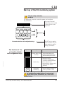
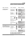
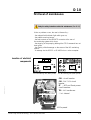
C 10
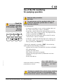
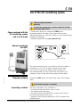
Start-up of the M3 monitoring system
Study the safety instructions
(see B 00)
The keyboard is used to control the pump and configure
the parameters.
The pump’s manual
control keys are located
Manual
control manuel
keys
Touches
de pilotage
on the top line of the
keyboard.
STOP
START PURGE ROOTS
WATER
Voyants
Indicators
SET
ENTER
FAULT
Touches
de sélection
et de and
configuration
des paramètres
Parameter
selection
configuration
keys
Symbol
SET
Description
Parameter setting mode
access key
Edition 04 - May 98
The functions of the
parameter selection
and configuration keys
ENTER
The SET key is used to
have access to the pulldown menu to read or
modify parameters.
Functions
• Used to have access to
the parameter setting mode
• Used to exit the various menus
without validating the functions
Selection keys
• Used have access to :
- the next or previous menu
- the next or previous parameter
in the displayed menu
• Used to select or adjust the value
of the parameter selected
previously
Configuration
validation key
• Used to validate the selection of
a menu, parameter or value
An insulating film protects the keys. Do not use hard
objects such as pens, screwdrivers, etc., which could
damage the key.
Alcatel - High Vacuum Technology - User’s Manual ADP/ADS
1/3
C 10
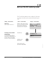
Start-up of the M3 monitoring system
The M3 monitoring system has been configured in the factory
according to the options and accessories defined during the
order.
Action / Observations
Display / Observations
Power ON :
(Main switch of M3 to I)
Display of the pump running
time, the pump status and the
date when the monitoring
have been set for transport.
Accessing to the parameter
programming :
The programming made at
the factory is protected by an
access code which disables
the entry of new parameters.
Press the key
SET
75H
LOC N2
PUMPING STOPPED
02/02/98
11 : 32 : 54
M3 VERSION 2.03
CODE : 0
Valid the code
with the key
ENTER
Acces code can be
personalized (see C 30)
2/3
Alcatel - High Vacuum Technology - User’s Manual ADP/ADS
Edition 04 - May 98
Setting / Observations
C 10
Start-up of the M3 monitoring system
Setting / Observations
Initializing the equipment
by updating the clock.
Action / Observations
Press the key repeatedly
to have access to
the SETTING MENU
Validate with the key
With the key
move through the menu
to DATE/TIME
Validate with the key
Display / Observations
ENTER
ENTER
Decrease or increase the
selected parameter using
the keys
Edition 04 - May 98
PURGE PRESS. SENSOR
SERIAL LINK
DATE/TIME
TEMPERATURE UNIT
DATE/TIME
MM/DD/AA
02/02/98
Validate the setting
SET
using the key
This action validates the
setting and moves onto the
next parameter
Set the STORAGE menu to save
the internal parameters during
transport or prolonged storage.
DEFINITION
SETTING MENU
MAINTENANCE MENU
OPERATING TIME
HH: MM: SS
11 : 32 : 54
Validate the settings and return
to the main menu with
ENTER
the key
DEFINITION
SETTING MENU
MAINTENANCE MENU
OPERATING TIME
Press the key repeatedly
to have access to
the STORAGE
Validate with the key
MAINTENANCE MENU
OPERATING TIME
STORAGE
CHANGE CODING
Press the key
ENTER
SET
Pumping cannot be started
(Seconds counter is blocked)
STORAGE
PUMPING STOPPED
03/23/98
18 : 24 : 80
Note : When you position the main switch to position I,
the storage mode disappears automatically :
Make a DATE/TIME setting (see previous paragraph)
Alcatel - High Vacuum Technology - User’s Manual ADP/ADS
3/3
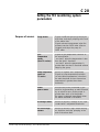
C 20
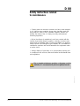
Setting the M3 monitoring system
parameters
Edition 04 - May 98
Purpose of sensors
Purge sensor
Signals insufficient gas purge during an
alert time, and stops pumping at the end
of the alarm time.
Signals exhaust overpressure when the
pressure reaches 1450 mbar (silencer
clogged) and stops the pump at
1990 mbar.
Gas
Temperature
sensor
(Non TC version)
Signals a gas temperature variation at
the exhaust with :
- an alert 1 when the temperature is less
than the alert 1 threshold
- an alert 2 when the temperature is
greater than the alert 2 threshold without
stopping the group.
Pump Temperature
sensor on
TC version
Allows to regulate ADP temperature.
Signals a pump temperature variation
(an alert when temperature is less than
the alert threshold and an alarm when
temperature is greater than alarm
threshold).
Motor
power sensor
Monitors the power consumed by the
machine by generating an alert followed
by an alarm as soon as the power is
greater than each of its thresholds;
the pump is stopped immediately when
the alarm threshold is exceeded.
E Analogic sensor
Allows to monitor a voltage on an input
contact with 2 adjustable thresholds.
E1 and E2 logic
sensors
Allows to monitor a logic sensor during
an alert time and stop pumping at the
end of the alarm time.
Alcatel - High Vacuum Technology - User’s Manual ADP/ADS
1/2
C 20
Setting the M3 monitoring system
parameters
Summary table of
monitoring parameters
Max. and Min.
thresholds :
SENSORS
UNIT THRESHOLD
FACTORY
CONFIGURATION
Mini Maxi
mbar 600
min
0
Purge sensor
Alert
900
60
{
0
< 20°
> 160°
Alarm
860
Disabled
-
Gas temperature sensor
°C
0
170
Pump θ° sensor (TC)*
°C
20
130
110
120
Motor power sensor
W
500 5000
2500
4000
E. analogical sensor
mV
0
E1. logic sensor
min
0
60
Disabled
Disabled
E2. logic sensor
min
0
60
Disabled
Disabled
10000 Disabled
Disabled
The pump may be started. The operation monitoring depends
on the fault programming. However, the M3 monitoring system
may be customized according to the current application, by
programming the parameters, pump stopped, of the various
menus listed on C 30.
Edition 04 - May 98
*Temperature regulation occurs 10°C below the alert threshold.
2/2
Alcatel - High Vacuum Technology - User’s Manual ADP/ADS
C 30
M3 Monitoring system
function table
Initial configuration (bold)
DEFINITION
INLET VALVE OPTION
ANA. INPUT SELECT
E1 LOGIC INPUT
E2 LOGIC INPUT
SYSTEM SELECTION
AUTOMATIC RESTARTING
ROOTS CONTROL
BUZZER CONTROL SELECT.
PURGE CONTROL SELECT.
THERMO CONTROLLED
FLOW N2 OPTION
Valid/Disabled
Valid/Disabled
Valid/Disabled
Valid/Disabled
ADS151/ADS301/ADS501/ADS801/1001
ADP81/ADP81V/ADP31/ADS501V
Valid/Disabled
Valid/Disabled
Valid/Disabled
Valid/Disabled
Valid/Disabled
Valid/Disabled
( Technical modifications reserved )
Edition 04 - May 98
Other menus
next page
Alcatel - High Vacuum Technology - User’s Manual ADP/ADS
1/3
C 30
M3 Monitoring system
function table
Other menus
next page
PURGE FLOW SENSOR
Alert time
Alarm time
TEMP. SENSOR
If Thermo controlled
“Disabled“:
Alert 1 threshold
Alert 2 threshold
If Thermo controlled
“valid“:
Alert threshold
Alarm threshold
0 to 60 min/Disabled
0 to 60 min/Disabled
0 to Alert 2
Alert 1 to 170° C
20° to Alarm threshold
Alert threshold to 130°C
ADP POWER SENSOR
Alert threshold
Alarm threshold
500 to Alarm threshold
Alert to 5000 W
ANA. INPUT SENSOR
Alert threshold
Alarm threshold
0 to Alarm threshold
E1 LOGIC. SENSOR
Alert time
Alarm time
0 to 60 min/Disabled
0 to 60 min/Disabled
E2 LOGIC. SENSOR
Alert time
Alarm time
0 to 60 min/Disabled
0 to 60 min/Disabled
PURGE FLOW PROLONGED
0 to 120 min
Initial config. : 10 min
PURGE PRESS. SENSOR
600 to 900 mbar
Initial config. 860 mbar
SERIAL LINK
Type
Echo
Address
Speed
Parity
Stop bit
RS232/RS485/NETWORK
Valid/Disabled
0 to 999
300 - 9600
Even/None/Odd
1 or 2
DATE, TIME
TEMPERATURE UNIT
PRESSURE UNIT
Time/Date menu
Celsius/Fahrenheit
mbar, hPa, Torr, PSI
Initial config. : °C
Initial config. : mbar
Alert threshold to 10 000 mV
( Technical modifications reserved )
2/3
Alcatel - High Vacuum Technology - User’s Manual ADP/ADS
Edition 04 - May 98
SETTING
C 30
M3 Monitoring system
function table
MAINTENANCE MENU
OPERATING TIME
MAINTENANCE TIME
OVERHAUL ADP
ADP LP BEARINGS
INSPECT SILENCER
OVERHAUL ROOTS
1000/34000
1000/17000
1000/17000
1000/34000
h
h
h
h
Initial Config :
8500 h
8500 h
2500 h
8500 h
DISPLAY
STORAGE
CHANGE CODING
INPUT THE NEW CODE:
Using
and
Edition 04 - May 98
input the new code
and valide with
LAST ALERTS
DISPLAY LAST
10 ALERTS
LAST ALARMS
DISPLAY LAST
10 ALARMS
CONFIGURATION
LIST OF CUSTOMIZED
PARAMETERS
key,
ENTER
( Technical modifications reserved )
Alcatel - High Vacuum Technology - User’s Manual ADP/ADS
3/3
C 40
Use of the M3 monitoring
for pumping operation
Study the safety precautions
(voir B 00)
Check the
rotational direction
of the pump, upon first
start-up
(See B 130)
STOP
SET
START PURGE ROOTS
ENTER
The performances and the operational safety of this
product are guaranteed provided that it is used in
normal operating conditions.
• Pre-adjustements :
- to ensure a gas purge as soon as the pumping starts, set
the ‘’Select. CMD Purge’’ menu on disabled
- to start-up or stop the gas purge during pumping set the
‘’Select. CMD Purge’’ menu on valid. The purge will start
or stop by pressing the ‘’PURGE’’ key
- to start-up the Roots at the same time as the ADP, set the
‘’Roots control’’ menu on disabled
- to start-up or stop the Roots while the ADP is running, set
the ‘’Roots control’’ menu on valid. The Roots will start or
stop by pressing the ‘’ROOTS’’ key.
Edition 04 - May 98
• Start-up the pumping by pressing “START”, the monitoring
system performs the following operations :
- opening the inlet valve (if preselection has been validated),
- ADP pump start-up,
- opening the water valve,
- data capture and sensor processing,
- opening the purge gas valve (if preselection has been
validated),
- Roots pump start-up.
At the same time the operating
parameters are shown.
15 H *N2* ROOTS
CHECK PRESSURE 940 MBAR
GAS TEMP. / ADP TEMP
ADP POWER
The pumps are equipped with an exhaust pressure monitoring
sensor. When this is not used, it is the responsibility of the
user to prevent the risks related to excess pressure of the installation.
Alcatel - High Vacuum Technology - User’s Manual ADP/ADS
1/2
C 40
Use of the M3 monitoring
for pumping operation
Operation monitoring
During operation, the user is warned of an operating
incident by :
- one or more fault are displayed on the screen, alternating
with monitoring parameters. When these faults are
parameter programmable, the monitoring system triggers
the alert phase followed by the alarm phase. The period
for these phases is programmable.
- indicators light and buzzer sounded, if option selected.
- the fault contacts on the REMOTE connector at the rear of
the monitoring unit are closed.
- pumping is stopped.
A list of incidents is given in the chapter D.
Avoid moving a pump in operation
Pumping shut-down
Press the “STOP” key, the monitoring system performs the
following operations :
When the stoppage is caused by a power cut, automatic
restarting is possible if “AUTOMATIC RESTARTING” has been
enabled.
When the pump has been configurated for automatic
restart after a power failure, it is the responsibility of the
user to take all the measures required to prevent risks resulting
from this type of operation
Remote control
2/2
M3 monitor enables other operating modes, particularly control
by PC via RS 232 interface and RS 485 (see section B 150) or
the remote control via the connector Remote (see section B 140).
Alcatel - High Vacuum Technology - User’s Manual ADP/ADS
Edition 04 - May 98
- pump stopping,
- water valve closing,
- injection of purge gas is continued during the shutdown
phase (if programmed),
- when the pump is fitted with an exhaust valve or inlet valve,
this valve is closed when pumping stops.
C 50
Use of the M1 monitoring system
Study the safety precautions
(see B 00)
For the first pump start-up, check the rotational direction
of the pump (see B 130)
Pump equipped with the
M1 monitoring system
and in local mode
• Set the main switch to I, actuate the START switch :
the pumping starts, the water valve opens and the green
indicator light goes on. (The hour counter is only increased when
the pump is operating).
• Adjust the water flow rate (see section B 120).
Remote monitoring
unit (M1)
DEFAULT
TEMP
012345
0
M
E
R G E
E
N
C
Y
S T O P
Rear view
5 or 10 m
Edition 03 - May 97
The remote monitoring unit is connected to the unit located on
the frame via a 5 or 10 m cable, connected at the front.
In this case, all controls are made from the remote unit.
The frame-mounted unit only contains the main switch, the
emergency stop and the monitoring system indicator lights.
Stopping pumping
Actuate the STOP switch, the water valve closes; the pumping
stops.
Avoid moving a pump in operation
Operating incidents
The user is informed of any incidents by :
• the fault indicator light which goes on (red),
• the audible warning buzzer,
• the fault contacts on the REMOTE connector at the rear of
the monitoring system which close,
• stopping of the pumping although the STOP command has
not been given.
Alcatel - High Vacuum Technology - User’s Manual ADP/ADS
1/2
C 50
Use of the M1 monitoring system
The remote control function is performed by means of the
“REMOTE” remote control connector at the rear of each fixed
monitoring unit.
It is used for :
• The remote control of the pump “START/STOP/ Emergency
Stop” functions.
• Copying monitoring parameters in dry contact form
(250 V - 1 A - 100 VA). These contacts may be used for
controlling automatic control systems. (see section B 140).
Edition 03 - May 97
The M1 monitoring system
can be remote controlled
2/2
Alcatel - High Vacuum Technology - User’s Manual ADP/ADS
D 00
Safety instructions related
to maintenance
This chapter describes the main preventive maintenance
operations and provides a guide for first diagnosis in the event
of an incident.
Standard precautions before any maintenance operation :
Before performing a maintenance operation, switch off
the pump by setting the main switch to “0” and disconnect
the mains cable.
CAUTION : before any operation, check the pumping
conditions of the installation : toxicity, corrosion, possible
radioactivity of the pumped gases.
Product tightness is guaranteed upon leaving the factory for
normal operating conditions. It is the responsibility of the user
to ensure that the level of tightness is maintained when pumping
dangerous gases.
Edition 04 - May 98
Depending on the case, we recommend :
• to purge the installation with dry nitrogen. The flush is performed
automatically when the pump is stopped (normal stop, or due to
a fault) if a maintained level of purge gas has been programmed.
Otherwise, proceed as follows:
- If the pump is remote controlled, remove the connections on
the REMOTE connector, at the rear of the monitor, and connect
the plug connector (supplied with the machine) instead.
- Adjust the parameters of the M3 monitor and program a
maintained level of purge gas for 10 minutes.
- Press START, followed by STOP on the front panel. The flush is
performed after the machine is stopped.
• to wear gloves, protective glasses and, if necessary, a breathing
mask.
• to ventilate the premises well.
• not to dispose of residue but, if necessary, to have it destroyed by
a qualified organization.
Alcatel - High Vacuum Technology - User’s Manual ADP/ADS
1/2
D 00
Safety instructions related
to maintenance
• Certain gases can become corrosives and toxic when trapped
in oil. Always wear protective gloves when handling used and
dirty pump oil, drain it into a closable container, and do not
breathe the fumes of the oil. Always use fully self-contained
breathing apparatus.
• When the silencer is maintained, avoid any contact with the
reaction by-products (deposit, powder..) strongly corrosive: wear
gloves even a breathing mask. Cleaning procedure can produce
violent reactions and dangerous gas releases. We recommend to
ventilate the premises well and disassemble the equipment under
a suction hood.
• Always dispose of used dirty oil, or sub-products properly and
in compliance with all local, state and federal environmental laws
and regulations.
Edition 04 - May 98
After a complete maintenance operation, on the pump or on the
installation, it is recommended to perform a tightness test with
helium.
2/2
Alcatel - High Vacuum Technology -User’s Manual ADP/ADS
D 10
First level of maintenance
Study the safety instructions related to maintenance (See D 00).
When a problem occurs, the user is informed by :
- the relevant fault indicator light which goes on,
- the audible warning buzzer,
- the fault contacts on the REMOTE connector at the rear of
the monitoring system which close,
- the stopping of the pumping although the STOP command has not
been given,
- the display of fault message on the screen of the M3 monitoring
system,
- a message via the RS 232 or RS 485 link on a micro-computer.
Location of electrical
components
J5
J5
CB2
RT1 CB1
TR1
TR1
J2 J3 J4
J1 J2 J3
M1 Monitoring unit (Rear panel)
CB1
CB2
Edition 04 - May 98
RT1
Monitoring
RT3 for ADS801/1001
RT2
J6
CB2
RT1 CB1
J1
M3 Monitoring unit (Rear panel)
CB1 : circuit breaker
CB2 : Ext* 24V circuit
breaker
RT : ADP and Roots power
circuit breakers
TR1 : Int* transformer
* Int : internal
ADS Unit
ADS opened
Alcatel - High Vacuum Technology - User’s Manual ADP/ADS
1/2
D 10
First level of maintenance
Preventive
maintenance with
monitoring system M1
The overall operating time of the machine can be read on
the front of the monitoring units (M1).
This is also used to calculate the operating time of the various
components which require maintenance.
The replacement frequency of certain components depends
directly on the type of process used. (See section D 20)
Maintenance time
monitoring with
monitor system M3
See Section E
Edition 04 - May 98
Maintenance
operations
Depending on the maintenance parameters programmed,
when the operating time before maintenance has expired,
the screen display alternates between operating parameters
and the message “ALERT MAINTENANCE”, the “FAULT”
indicator is lit.
Press the “SET” button during pumping and the operating times
for components are displayed in turn.
This information can be red at any time using the
“Operating time” menu. Perform maintenance on the relevant
parts.
2/2
Alcatel - High Vacuum Technology -User’s Manual ADP/ADS
D 20
Maintenance frequency
Edition 04 - May 98
ADP 31 - ADP 81
Roots 151 - 301 - 601
Roots 1001/1501
C
B
A
Description
8500 H
13000 H
25000 H
For processes 1 (See section B 120)
Time
required
Equipment required
Part
Description
number
LP bearing
replacement
Minor kit
30 min (31/81)
Full overhaul
10 H* Major kit (31)
12 H* Major kit (81)
ALCATEL 113 oil
(0.5 L)
Full overhaul
8 H*
090576
040162
061925
064657
Specific
tool
Comments
Consult
Alcatel
Consult
Alcatel
Major kit (151)
100068 051940
Major kit (301/601) 090839
ALCATEL 113 oil
064657
(0.5 L) Qty : 2 for 301
& 601
**
2 oil fillings
for 301 et 601
**
Full overhaul
A:
A+B :
A+C :
12 H* Major kit
ALCATEL 113 oil
(0.5 L) Qty : 6
ADP 31 - ADP 81 Maintenance
ADS 151 / 301 / 501 Maintenance
ADS 801/1001 Maintenance
101109
064657
6 oil fillings
**
* Testing and cleaning time not included
** For oil filling, see section B 50
Maintenance times can change according to processes and equipments used.
Alcatel - High Vacuum Technology - User’s Manual ADP/ADS
1/3
D 20
Maintenance frequency
Time
required
Equipment required
Part
Description
number
Silencer cartridge
control (1)
15 min Silencer cartridge
040095
LP bearing
replacement
Minor kit
30 min (31/81)
090576
Full overhaul
10 H* Major kit (31)
12 H* Major kit (81)
ALCATEL 113 oil
(0.5 L)
Full overhaul
8 H*
040162
061925
064657
Specific
tool
Comments
Equipped
silencer available
Ref : 100210
Consult
Alcatel
Consult
Alcatel
Major kit (151)
100068 051940
Major kit (301/601) 090839
ALCATEL 113 oil
064657
(0.5 L) Qty : 2 for 301
& 601
**
2 oil fillings
for 301 et 601
**
Full overhaul
A:
A+B :
A+C :
12 H* Major kit
ALCATEL 113 oil
(0.5 L) Qty : 6
ADP 31 - ADP 81 Maintenance
ADS 151 / 301 / 501 Maintenance
ADS 801/1001 Maintenance
101109
064657
6 oil fillings
**
* Testing and cleaning time not included
** For oil filling, see section B 50
Maintenance times can change according to processes and equipments used.
(1) With TC version and silencer heating, the maintenance of the silencer can be extanded
to 8500 h.
2/3
Alcatel - High Vacuum Technology -User’s Manual ADP/ADS
Edition 04 - May 98
ADP 31 - ADP 81
Roots 151 - 301 - 601
Roots 1001 - 1501
C
B
A
Description
4200 H
8500 H
17000 H
For processes 2 (See section B 120)
D 20
Maintenance frequency
ADP 31 - ADP 81
Roots 151 - 301 - 601
Roots 1001 - 1501
Edition 04 - May 98
C
B
A
Description
2100 H
4200 H
8500 H
For processes 3 (See section B 120)
Tme
required
Equipment required
Part
Description
number
Silencer cartridge
control
15 min Silencer cartridge
040095
LP bearing
replacement
Minor kit
30 min (31/81)
090576
Full overhaul
10 H* Major kit (31)
12 H* Major kit (81)
ALCATEL 113 oil
(0.5 L))
Full overhaul
Full overhaul
A:
A+B :
A+C :
8 H*
040162
061925
064657
Specific
tool
Comments
Equipped
silencer available
Ref : 100210
Consult
Alcatel
Consult
Alcatel
Major kit (151)
100068 051940
Major kit (301/601) 090839
ALCATEL 113 oil
064657
(0.5 L) Qty : 2 for 301
& 601
12 H* Major kit
ALCATEL 113 oil
(0.5 L) Qty : 6
ADP 31 - ADP 81 Maintenance
ADS 151 / 301 / 501 Maintenance
ADS 801/1001 Maintenance
Included in
full overhaul
101109
064657
**
**
**
* Testing and cleaning time not incluede
** For oil filling, see section B 50
Maintenance times can change according to processes and equipments used.
Alcatel - High Vacuum Technology - User’s Manual ADP/ADS
3/3
D 30
Diagnosis and troubleshooting
D 40
The pump is running and then is showing
an alert or alarm message
(followed by the pumps stopping) . . . . . . . . . .
D 50
The pump is running (no message) . . . . . . . . .
D 60
Edition 03 - May 97
Pump does not start . . . . . . . . . . . . . . . . . . .
Alcatel - High Vacuum Technology - User’s Manual ADP/ADS
1/1
D 40
Pump does not start
INCIDENT
CAUSE
The display is not lighting up
or no display
No mains
TROUBLESHOOTING
Check power supply
NO
Isolating switch is off
NO
CB1 breaker switched off
Switch it on
Version before 96/12:
Push on the red button untill
zero and release.
Since 97/01
Push on the blue button
untill zero.
Check the calibration
Switch it on
NO
Edition 04 - May 98
Other problem
The keyboard is not working
Alcatel - High Vacuum Technology - User’s Manual ADP/ADS
Call Alcatel customer service
Call Alcatel customer service
1/4
D 40
Pump does not start
INCIDENT
CAUSE
TROUBLESHOOTING
Pressing on “Start“ does
not start-up the pump
Roots is not running
Bad M3 configuration
Configure for “ADS“
and/or disable Roots
NO
Command “Roots valid“ not
programmed
Check the setting
NO
Press on key “Roots“
Roots does not run and
“Roots“ message is
displayed
No * presence
near Roots
Check presence or connect
jumper plug RP
NO
“Roots “J3 plug
bad connected
Check the connection
ADP does not run
Problem on M3
Call Alcatel customer service
“ADP“ plug
bad connected
Check the connection
NO
Defective management
board
2/4
Call Alcatel customer service
Alcatel - High Vacuum Technology -User’s Manual ADP/ADS
Edition 04 - May 98
NO
D 40
Pump does not start
INCIDENT
CAUSE
TROUBLESHOOTING
Pump in storage mode
Set the main switch on “0“,
then set it again on “1“.
On Remote mode
Check the connection of J7.
See section B 140.
Messages on the display
Message “STOCK“
Message “REM“
No RP plug or bad connection
NO
Alarm “Breaker KM2“
Problem on M3
Call Alcatel customer service
Roots KM2 Contactor
Check the condition and the
connection of the contactor
(See D 70 ).
Edition 04 - May 98
NO
Alarm “Breaker RT1“
ADP RT1 breaker
NO
Alarm “Breaker RT2“
Roots RT2 breaker
NO
Switch it on.
Check its rate.
(See D 70 ).
Check ADP mechanical
condition.
Switch it on.
Check its rate.
(See D 70 ).
Check ADP mechanical
condition.
See next page 4/4
Alcatel - High Vacuum Technology - User’s Manual ADP/ADS
3/4
D 40
Pump does not start
INCIDENT
Alarm “Breaker KM1“
CAUSE
TROUBLESHOOTING
ADP KM1 Contactor
Check the condition and the
connection of the contactor
(See D 70 ).
NO
Alarm “Breaker EMO“
Emergency switch
Switch it on
(See D 70 ).
NO
Exhaust pressure
≥ 1450 mbar
“Starting phase“
Main power is not correct
No message displayed on
the screen
4/4
Problem on M3
See D 80
Check the main power.
Call Alcatel customer service
Alcatel - High Vacuum Technology -User’s Manual ADP/ADS
Edition 04 - May 98
Alarm “Pressure“
D 50
The pump is running and then is
showing an alert or alarm message
(followed by the pump stopping)
INCIDENT
Alert “Pressure“
CAUSE
Exhaust pressure
= 500 mbar
TROUBLESHOOTING
Check the connection
(See D 80)
NO
See D 80
Exhaust pressure
> 1990 mbar
See D 80
Edition 04 - May 98
Alert “Pressure“
Exhaust pressure
> 1450 mbar
Alcatel - High Vacuum Technology - User’s Manual ADP/ADS
1/9
D 50
The pump is running and then is
showing an alert or alarm message
(followed by the pump stopping)
INCIDENT
“Gas Temp.“ Alert
CAUSE
θ gas lower than
alert threshold 1
TROUBLESHOOTING
See D 90
NO
θ gas higher than
alert threshold 2
See D 90
NO
Sensors not connected
θ gas = 170°C
Check the connection
NO
“Consumption“ Alert
“Consumption“ Alarm
2/9
Consumption higher than
alert threshold or no power
See D 90
See D 100
Alcatel - High Vacuum Technology -User’s Manual ADP/ADS
Edition 04 - May 98
Problems on
platinium sensor
D 50
The pump is running and then is
showing an alert or alarm message
(followed by the pump stopping)
INCIDENT
“Water flow“ Alert
CAUSE
Insufficent water flow
TROUBLESHOOTING
See D 110
NO
Sensor not connected
Check the connection
NO
Edition 04 - May 98
Sensor out of order
Call Alcatel customer service
Unreadable flowmeter
graduation (blocked ball)
Deposits in the flowmeter
Clean the flowmeter
“Power supply“ Alert
Mains voltage variation
(± 15%)
Check the voltage
NO
Problem on M3
Alcatel - High Vacuum Technology - User’s Manual ADP/ADS
Call Alcatel customer service
3/9
D 50
The pump is running and then is
showing an alert or alarm message
(followed by the pump stopping)
INCIDENT
“Pump temp.“ Alert
CAUSE
Pump θ higher than
alert threshold
TROUBLESHOOTING
See D 91
NO
“Pump temp.“ Alarm
Problem on the platinium
sensor
See D 91
Pump θ higher than
alarm threshold
See D 91
NO
Check the wiring
NO
Problem on the platinium
sensor
4/9
See D 91
Alcatel - High Vacuum Technology -User’s Manual ADP/ADS
Edition 04 - May 98
Sensor not connected
θ gas = 170°C
D 50
The pump is running and then is
showing an alert or alarm message
(followed by the pump stopping)
INCIDENT
“Motor temp.“ Alert
θ ADP motor ≥ 52°
CAUSE
Cooling problems
TROUBLESHOOTING
See D 110
NO
ADP mechanical problems
See E 50
NO
Defect does not disappear
“Motor temp.“ Alarm
θ ADP motor ≥ 65°
Cooling problems
Call Alcatel customer service
See D 110
NO
Edition 04 - May 98
ADP mechanical problems
See E 50
NO
Defect does not disappear
Alcatel - High Vacuum Technology - User’s Manual ADP/ADS
Call Alcatel customer service
5/9
D 50
The pump is running and then is
showing an alert or alarm message
(followed by the pump stopping)
INCIDENT
CAUSE
TROUBLESHOOTING
Alert or alarm “Purge N2“
Alert and alarm are switched on according to the
delays programmed in M3
configuration
Without flow purge
sensor option
Exhaust pressure
P = 500 mbar
See D 80
NO
See D 80
No nitrogen
See D 80
Edition 04 - May 98
With flow purge
sensor option
500 mbar < P < Pres. threshold
NO
Flowmeter bad set
6/9
See D 80
Alcatel - High Vacuum Technology -User’s Manual ADP/ADS
D 50
The pump is running and then is
showing an alert or alarm message
(followed by the pump stopping)
INCIDENT
“Analogic input“
Alert or alarm
CAUSE
Valid input after
configuration and not used
TROUBLESHOOTING
Reset M3 configuration
NO
Problem on the
display/voltage
Thresholds not properly set
Check the corresponding
voltage
(See D 130)
Set the thresholds
NO
Connection problems
Edition 04 - May 98
“E1 logic“ or “E2 logic“
Alert or alarm
Valid input after
configuration and not used
Check the connection
(See D 130)
Reset M3 configuration
NO
Sensor problems
Check the sensors
(See D 140)
NO
Delay not properly set
Alcatel - High Vacuum Technology - User’s Manual ADP/ADS
Set the delays
7/9
D 50
The pump is running and then is
showing an alert or alarm message
(followed by the pump stopping)
INCIDENT
“Valve option“ Alert
CAUSE
Valid option after
configuration and not used
TROUBLESHOOTING
Reset M3 configuration
NO
Valve does not close when
pump is stopping
Check the compressed air
supply.
Check the valve condition.
NO
Contact problems
“Valve option“ Alarm
Valid option after
configuration and not used
See D 150
Reset M3 configuration
Valve does not open when
pump is starting
Check the compressed air
supply.
Check the valve condition.
NO
Contact problems
8/9
See D 150
Alcatel - High Vacuum Technology -User’s Manual ADP/ADS
Edition 04 - May 98
NO
D 50
The pump is running and then is
showing an alert or alarm message
(followed by the pump stopping)
INCIDENT
“Variator“ Alert
CAUSE
Valid option
(ADP 81V, ADS 801/1001
or ADS 501V)
when it is not necessary
TROUBLESHOOTING
Reset M3 configuration.
NO
Pump is stopped
Check variator parameter
on ADS 801.
(See D 160)
NO
Wiring problems
The maintenance threshold
of a parameter is reached
Edition 04 - May 98
“Maintenance“ Alert
(ADP, Bearings, Silencer
or Roots)
Alcatel - High Vacuum Technology - User’s Manual ADP/ADS
Check the connection.
(See D 160)
Perform maintenance
operation and reset the
corresponding time.
Check the maintenance
thresholds.
9/9
D 60
The pump is running - No message
INCIDENT
Bad vacuum
or no vacuum
CAUSE
TROUBLESHOOTING
Polluted or filled in pumps
Maintenance ADP
Call Alcatel customer service
NO
Mechanical noise
Internal oil leaks
Maintenance ADP
Call Alcatel customer service
Damaged ball bearings
Maintenance ADP
Call Alcatel customer service
NO
Rotors seizing
Maintenance ADP
Call Alcatel customer service
NO
Edition 04 - May 98
Unsynchronized gears
No N2 purge
Bad configuration
Alcatel - High Vacuum Technology - User’s Manual ADP/ADS
Maintenance ADP
Call Alcatel customer service
Reset M3 configuration or
set the purge manually.
1/1
D 70
“Breaker …“ Alarm
“Breaker KM2“ Alarm
Roots KM2 Contactor
“Breaker RT1“ Alarm
ADP RT1 Breaker
• Check the breaker CB2, on M3 rear panel
• If the message still remains, call Alcatel customer service
RT 1 breaker is not in
position 1
NO
No wattmeter plug and its
strap between 4 & 6
- Check its position
- Check ADP mechanical
condition (See E 50)
- Check that the silencer
is not clogged (See E 30).
Set the plug and the strap
Edition 04 - May 98
NO
“Breaker RT2“ Alarm
RT2 Roots breaker
Problem on M3
Call Alcatel customer service
RT 2 Roots braeker is not
on position 1
- Check its position
- Check Roots mechanical
condition
NO
Problem on M3
Alcatel - High Vacuum Technology - User’s Manual ADP/ADS
Call Alcatel customer service
1/2
D 70
“Breaker …“ Alarm
“Breaker KM1“ Alarm
ADP KM1 contactor
• Check CB2 breaker at the rear of M3.
(see D 10 ).
• Check the strap presence between the pins 41, 42, 43
and 44 on remote plug. (see B 140).
• If the defect still remains, call Alcatel customer service.
“Breaker EMO“ Alarm
Emergency stop
• Check that the emergency stop button is not tripped (unlock
it by rotating 1/4 of turn).
Edition 04 - May 98
• If the defect still remains, call Alcatel customer service.
2/2
Alcatel - High Vacuum Technology -User’s Manual ADP/ADS
D 80
“Pressure“ Alert and alarm
“N2 Purge“ Alert and alarm
Exhaust pressure higher
than threshold
“Pressure“ Alert and alarm
• Check the nitrogen pressure setting according to
section B 120.
• Check that the silencer, the pipe to exhaust are not
clogged.
Edition 04 - May 98
• If the defect still remains, call Alcatel customer service.
Alcatel - High Vacuum Technology - User’s Manual ADP/ADS
1/2
D 80
“Pressure“ Alert and alarm
“N2 Purge“ Alert and alarm
Exhaust pressure level
between 500 mbar and
threshold set
“N2 Purge“ Alert and alarm
Without Nitrogen flow
sensor option
- Either check the connection, the display and nitrogen pressure
setting (idem exhaust pressure too high see page 1/2).
- If there is no N2 pressure, check nitrogen supply, connections,
electrovalve and the coil and its connection.
- If the incident is still present, there is another problem
on the M3: call Alcatel customer service.
With Nitrogen flow
sensor option
(The flowmeter is connected
instead if E2. Log.)
- Check nitrogen supply, electrovalve and its coil.
- Check the nitrogen detector setting.
- Check the nitrogen detector wiring by shunting pins 23 & 24
of J5.
The defect disappears
Check the wiring.
NO
Call Alcatel customer service.
Edition 04 - May 98
Problem on M3
Exhaust pressure
= 500 mbar
Check that the sensor is properly connected.
- Test the connection and the display (idem exhaust pressure
too high see page 1/2).
- If the incident is still present, call Alcatel customer service.
2/2
Alcatel - High Vacuum Technology -User’s Manual ADP/ADS
D 90
“Gas temp.“ Alert
- Check the thresholds.
- Check the flowrate, the kind and the concentration of pumped
gases.
- Check that the exhaust pipe is not clogged.
- Check the display :
• θ ambient when pump is stopped.
• θ : 100°C in continuous operation.
- Check the wiring and the sensor : the resistance between
pins 1 & 2 of J6 must be between 100 and 160 Ω.
(J6 unpluged)
•
•
•
•
•
•
0°C
20°C
50°C
80°C
100°C
157°C
:
:
:
:
:
:
100 Ω
107,8 Ω
119,4 Ω
130,9 Ω
138,5 Ω
160 Ω
Edition 04 - May 98
- If the sensor is OK, there is another problem on the M3:
call Alcatel customer service.
Alcatel - High Vacuum Technology - User’s Manual ADP/ADS
1/1
D 91
“Pump temp.“ Alert
- Check the thresholds.
- Check the display :
• θ ambient when pump is stopped.
• θ : 100°C in continuous operation.
- Check the wiring and the sensor : the resistance between
pins 1 & 2 of J6 must be between 100 and 160 Ω.
(J6 unpluged)
•
•
•
•
•
•
0°C
20°C
50°C
80°C
100°C
157°C
:
:
:
:
:
:
100 Ω
107,8 Ω
119,4 Ω
130,9 Ω
138,5 Ω
160 Ω
- Check the cooling circuit.
Edition 01 - May 98
- If the sensor is OK, there is another problem on the M3:
call Alcatel customer service.
Alcatel - High Vacuum Technology - User’s Manual ADP/ADS
1/1
D 100
“Consumption“ Alert and alarm
Consumed power higher than
alert or alarm thresholds
- Check the threshold setting.
- Check the flowrate, the kind and the concentration of pumped
gases.
- Check that exhaust pipe are not clogged.
- Check that there is no mechanical problem (seizing), or
filling in in the pumping line.
- Check LP bearings.
- Check the rotational direction of the pump.
- If the incident is still present, call Alcatel customer service.
Consumed power = 0 W
Rotational direction of the
pump not correct
Invert two phases on mains
plug J1
Edition 04 - May 98
NO
Problem on M3
Alcatel - High Vacuum Technology - User’s Manual ADP/ADS
Call Alcatel customer service.
1/1
D 110
“Water flowrate“ Alert
CAUSE
Insufficent water flow
TROUBLESHOOTING
- Check the flowmeter setting according to section B 120.
- Check that the electrovalve, the flowmeter or the pipes are not
clogged.
- Check that there is no leak.
No water flow
- Either check the water supply and the connections.
- Check the connection and the water valve coil condition.
Water flow OK
Edition 04 - May 98
Check the wiring of the
flowmeter by shunting
the pins
9 and 10 of J5
The defect disappears
Remake the wiring.
Change the setting of flow
controller
(see A 30 rep. 12)
NO
Problem on M3
Alcatel - High Vacuum Technology - User’s Manual ADP/ADS
Call Alcatel customer service.
1/1
D 120
“Motor temp.“ Alert or alarm
ADP motor temperature
higher than the thresholds
- Check the water flowrate in the pump (see D 110).
- Check the motor temperature.
Case of an alert
- Check the sensor and the wiring by shunting pins 21 & 22
of J5.
The defect disappears
Remake the wiring or
change the sensor
NO
Problem on M3
Case of an alarm
Call Alcatel customer service.
- Check the sensor and the connection by shunting pins
19 & 20 of J5.
The defect disappears
Remake the wiring
(see B 80)
Edition 04 - May 98
NO
Problem on M3
Alcatel - High Vacuum Technology - User’s Manual ADP/ADS
Call Alcatel customer service.
1/1
D 130
“Analogic input“ Alert or alarm
Wiring or display
problem
Check the threshold setting
See C 30
Check the display
according to the DC input
voltage between pins
14 & 15 of J6 (15 = 0V)
Call Alcatel customer service.
NO
Check the status of
analogical sensor
(Customer one)
Edition 04 - May 98
Problem on analogical
sensor
Alcatel - High Vacuum Technology - User’s Manual ADP/ADS
1/1
D 140
“E1 logic“ Alert or alarm or
“E2 logic“ Alert or alarm
Sensor or connection
problem
E1 logic
Check the threshold setting See C 30
Shunt the sensor
The defect disappears
NO
Problem on M3
E2 logic
Call Alcatel customer service.
Call Alcatel customer service.
Unplug the sensor
The defect disappears
Edition 04 - May 98
Remake the wiring :
it must be continuity
between pins
11 and 12 of J5.
Check the sensor status.
Remake the wiring :
it must not be continuity
between pins
23 and 25 of J5.
NO
Problem on M3
Alcatel - High Vacuum Technology - User’s Manual ADP/ADS
Call Alcatel customer service.
1/1
D 150
“Valve option“ Alert and alarm
Contact problem
Alert
Check the configuration of M3 parameters ( See C 30)
Check the wiring by shunting pins 7 & 8 of J5.
No defect at pump stop
Remake the wiring and
check valve contact
condition.
NO
Problem on M3
Alarm
Call Alcatel customer service.
Check the wiring by shunting pins 5 & 6 of J5.
No defect at pump start up
Remake the wiring and
check valve contact
condition.
NO
Call Alcatel customer service.
Edition 04 - May 98
Problem on M3
Alcatel - High Vacuum Technology - User’s Manual ADP/ADS
1/1
D 160
“Variator“ Alarm
Check the configuration of
M3 parameters (See C 30)
Configure on
ADS 801/1001, ADS 501V
or ADP 81V
NO
Call Alcatel customer service.
Edition 04 - May 98
Problem on M3
Alcatel - High Vacuum Technology - User’s Manual ADP/ADS
1/1
E 20
Pump draining
(Roots : front and rear casings)
Study the safety precautions before intervention. (See sheet D 00)
Certain gases become corrosive and toxic when trapped in oil.
Always wear protective gloves when handling used and dirty pump
oil, drain into a closable container, and do not breathe the fumes of the oil.
Always use fully self-contained breathing apparatus.
Always dispose of used or dirty oil, or sub-products properly and in
compliance with all local, state and federal environnemental laws and
regulations.
Housing oil replacement:
10
Unfasten the fill plug in order to eliminate any excess pressure in
the housing.
10
Remove the drain plug and allow the used oil to flow into a container
(capacity: 0.5 litre).
fill plug
oil level indicator
Edition 03 - May 97
drain plug
ROOTS
ADP
Caution: the Roots is equipped with 2 housings. Repeat the operation
for each housing.
Replace the drain plug and the remove the fill plug.
Introduce the quantity of new oil required (see Section B 50).
Alcatel - High Vacumm Technology - User’s Manual ADP/ADS
1/1
E 30
Silencer maintenance
Consult the standard precautions before intervention - see Section D 00
For quicker interventions and special precaution during cleaning, it is
recommended to replace all the parts (equipped silencer and outlet tube)
and repair the replaced parts on a bench.
When the silencer is maintained, avoid any contact with the reaction
by-products (deposit powder..) strongly corrosive : wear gloves even a
breathing mask.
REPLACEMENT
FREQUENCY
The ADP pump silencer repair work frequency
depends on the process used.
Refer to the maintenance frequency tables.
■ See Section D 20
SILENCER
REPLACEMENT
Edition 04 - May 98
Remove the side covers ■ See section B 20
and remove the silencer backplate located on
the rear panel of the pumping unit.
Disconnect the silencer from the pump exhaust
connector by removing the clamping ring and the seal
support ring. (Access via one of the side openings
located at the bottom of the frame)
Remove the assembly (silencer and outlet tube) from
the rear of the machine.
Reinstall a complete assembly (equipped
silencer and outlet tube).
Reinstall the backplate to the rear of the pumping
unit and the side covers. Perform the maintenance
of the replaced parts on a bench.
Alcatel - High Vacuum Technology - User’s Manual ADP/ADS
SEE FOLIO 2
1/3
E 30
Silencer maintenance
Refer to the special precautions before any intervention - see Section D 00
PART
CLEANING AND CARTRIDGE REPLACEMENT
,,,,,
,,,,,
Complete silencer (with cartridge)- Part No.: 100210
1
■ Parts to be replaced
Silencer maintenance kit
2
3
4
5
6
Part No. 040095 (items 2, 3, 4)
Separate the outlet tube from the silencer.
Remove the cover assembly.
Soak the silencer body in a bath of hot water and remove the deposit
located inside the silencer.
Remove the cartridge and the Borelly washer.
Loosen and remove the lock-nuts and the nuts to release the stop valve (5).
Remove the two O-rings (3 and 4).
Clean all the parts in a bath of hot water using a cloth if necessary.
Dry in the air or with compressed air.
Position the Borrelly washer (1) and install a new cartridge.
Reassemble the other parts by replacing the O-rings (3 and 4) with new
seals.
2/3
Alcatel - High Vacuum Technology - User’s Manual ADP/ADS
Edition 04 - May 98
4
E 30
Silencer maintenance
RESSETTING
MAINTENANCE PARAMETERS AFTER SILENCER MAINTENANCE OPERATION
When the maintenance of an element has been done, it is necessary to reset its meter to
stop the warning and reset the functionnal delay of this element.
Setting / Observations
Action / Observations
Accessing the parameter
programming :
The programming made at
the factory is protected by
an acceess code which
disables the entry of new
parameters
Press the key
Access in the
“MAINTENANCE” menu
Press the key
repeatedly to
access to
MAINTENANCE MENU
SET
Valid the code
with the key
ENTER
ENTER
DEFINITION
SETTING MENU
MAINTENANCE MENU
OPERATING TIME
ENTER
OVERHAUL ADP
ADP LP BEARINGS
INSPECT SILENCER
OVERHAUL ROOTS
ENTER
COUNTER SET
DURATION : 0 H
MAXI : 17000 H
MINI : 1000 H
Press the key
repeatedly to
access the chosen
MENU
STOP
Press the key
and
pressing
ACCESS CODE
CODE : 0
Press the key until
the code is obtained
Valid with the key
Acces to chosen parameter
menu.
Display / Observations
Edition 04 - May 98
STOP
Reset the parameter.
The fresh screen appears
Press the key
repeatedly
or
to reset the delay
Valid with the key
Alcatel - High Vacuum Technology - User’s Manual ADP/ADS
3/3
E 50
Freeing up the ADP
If, after a prolonged stop, the ADP does not restart using the function START
because of sub-products deposed inside the pump, it is possible to free it up
manually.
Consult the standard precautions before intervention. (See Section D 00)
• ACCESS
THE DRIVING SHAFT BEARING
Remove the protective cover (1) and remove
the O-ring by removing the three M4 x 10 CHc
screws.
3
• FREEING
1
UP BY ROTATING THE DRIVING SHAFT
Using the box wrench, move the driving shaft in
21 both directions of rotation until free rotation is
obtained.
Edition 03 - May 97
• REFIT
THE PROTECTIVE COVER
Clean the O-ring and grease it lightly with
vacuum grease.
Reinstall the O-ring and the protective cover.
3
•
RESTART THE PUMP
Restart by pressing the “START” switch on the monitor.
Alcatel - High Vacuum Technology - User’s Manual ADP/ADS
1/1