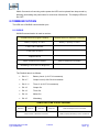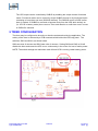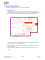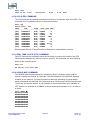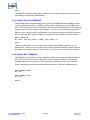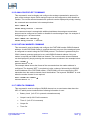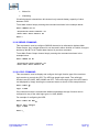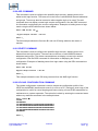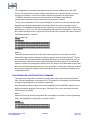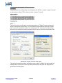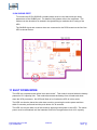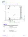
1
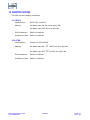
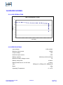
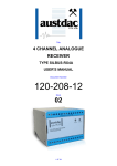
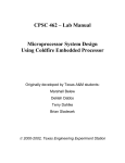
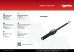
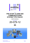
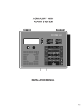
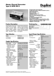
Title
Intrinsically Safe Ex ia UPS
Type 12/NMH/288
User’s Manual
Document Number
61-163-12
Issue
04
04
Add Certification Section
2014.03.29
PC
PC
MC
02
Updated for release 1V03
2013.12.11
PC
CG
PC
01
ORIGINAL
2013.11.26
PC
PC
MC
Issue
Details
Date
Written
Intrinsically Safe Ex ia UPS
Type 12/NMH/288
1 OF 3 0
Designed
Approved
61-163-12
Issue: 04
1 TABLE OF CONTENTS
1 TABLE OF CONTENTS..................................................................................................................2
2 INTRODUCTION ............................................................................................................................4
3 GENERAL DESCRIPTION .............................................................................................................4
4 WARNINGS AND PRECAUTIONS...............................................................................................5
4.1 USER ACCESS .........................................................................................................................5
4.2 STORAGE, INSTALLATION, USE AND MAINTAINANCE REQUIREMENTS...............5
4.2.1 Storage ................................................................................................................................5
4.2.2 Installation...........................................................................................................................6
5 MODES.............................................................................................................................................7
5.1 MAINS MODE ..........................................................................................................................7
5.2 BATTERY MODE ....................................................................................................................7
5.3 Sleep Mode ................................................................................................................................7
5.4 SHUT DOWN MODE ...............................................................................................................7
6 PHYSICAL DESCRIPTION ............................................................................................................8
7 TOP PANEL DESCRIPTION ..........................................................................................................8
7.1 OPERATION .............................................................................................................................8
7.2 BATTERY LEVEL....................................................................................................................9
7.3 TIMER .......................................................................................................................................9
7.4 SERVICE ...................................................................................................................................9
7.5 SYSTEM OK LED ..................................................................................................................10
7.6 INPUT POWER LED ..............................................................................................................10
7.7 FAST CHARGE LED..............................................................................................................10
7.8 TRICKLE CHARGE LED.......................................................................................................10
7.9 OUTPUT POWER ON ............................................................................................................10
7.10 START UP DIAGNOSTICS .................................................................................................10
7.11 POWER RESET PUSH BUTTON ........................................................................................10
7.11.1 Switch between Sleep and Battery Mode .......................................................................10
7.11.2 Restart Timer...................................................................................................................10
7.11.3 Shut Down Mode ............................................................................................................10
8 COMMUNICATIONS....................................................................................................................11
8.1 SILBUS....................................................................................................................................11
9 TIMER CONFIGURATION ..........................................................................................................12
10 UPS CONFIGURATION .............................................................................................................13
10.1 CONSOLE PORT ..................................................................................................................13
10.2 CONSOLE PORT OPERATION ..........................................................................................14
10.3 HELP (HELP) COMMAND..................................................................................................14
10.4 VERSION (VER) COMMAND ............................................................................................15
10.5 REPEAT (REP) COMMAND ...............................................................................................15
10.6 STACK (STACK) COMMAND ...........................................................................................16
10.7 DISPLAY (DISP) COMMAND ............................................................................................16
10.8 ERROR (ERROR) COMMAND ...........................................................................................17
10.9 UART (UART) COMMAND................................................................................................17
10.10 LOG (LOG) COMMAND ...................................................................................................18
10.11 REAL TIME CLOCK (RTC) COMMAND ........................................................................18
10.12 SILBUS MAP COMMAND................................................................................................18
10.13 SILBUS STATUS COMMAND .........................................................................................19
10.14 SILBUS GET COMMAND.................................................................................................19
Intrinsically Safe Ex ia UPS
Type 12/NMH/288
2 OF 30
61-163-12
Issue: 04
10.15 ANALOGUE SELECT COMMAND .................................................................................20
10.16 FASTLINK MARKER COMMAND..................................................................................20
10.17 SBDATA COMMAND .......................................................................................................20
10.18 SBPWR COMMAND..........................................................................................................21
10.19 LOGIC COMMAND ...........................................................................................................21
10.20 ADD COMMAND...............................................................................................................22
10.21 DELETE COMMAND ........................................................................................................22
10.22 UPLOAD CONFIGURATION COMMAND .....................................................................22
10.23 DOWNLOAD CONFIGURATION COMMAND..............................................................23
10.24 SILBUS Port ........................................................................................................................25
11 SHUT DOWN MODE ..................................................................................................................25
12 SERVICE MODE .........................................................................................................................26
13 SELF TEST MODE ......................................................................................................................26
14 INPUT SUPPLY CONSIDERATIONS .......................................................................................26
14.1 REFLECTED NOISE ............................................................................................................26
14.2 LOAD CURRENT SPIKES...................................................................................................26
14.3 INPUT/OUTPUT TERMINATIONS ....................................................................................26
15 CERTIFICATION ........................................................................................................................28
15.1 IECEx.....................................................................................................................................28
15.2 ATEX .....................................................................................................................................28
16 SPECIFICATIONS.......................................................................................................................29
16.1 LOAD REGULATION..........................................................................................................29
16.2 SPECIFICATIONS................................................................................................................29
17 GENERAL MOUNTING ARRANGEMENT .............................................................................30
18 CONTACT....................................................................................................................................30
Intrinsically Safe Ex ia UPS
Type 12/NMH/288
3 OF 30
61-163-12
Issue: 04
2 INTRODUCTION
This document specifies and describes the correct installation, operation, and servicing of the
Austdac UPS Type 12/NMH/288.
The UPS Type 12/NMH/288 is available with various input/output connector/terminal block
options.
3 GENERAL DESCRIPTION
The Austdac UPS Type 12/NMH/288 has been designed to provide battery backup for
equipment that operates from a nominal 12 volt supply and has a maximum current output of
1A.
The UPS has a secondary current limiter which provides enhanced capacitive load charging.
The secondary current limiter limits the output current to 0.9A.
The UPS has a built in charger that will charge the battery and support the specified load. This
eliminates the need for surface charging the battery.
The UPS uses Nickel Metal Hydride technology to provide the highest capacity to weight ratio
without the troublesome memory effect exhibited by Nickel Cadmium batteries.
The UPS has a built in display to provide users with the following important battery
parameters;
•
System Okay
•
Input Power Available
•
Battery Charge
•
Output Power
•
Service
•
Battery capacity
The UPS is also fitted with an optional timer that will disconnect the load after a predefined
time period operation in backup mode. A top panel mounted push button can be used to reset
the timer and provide load power for another time period. This timer can be disabled if not
required.
Intrinsically Safe Ex ia UPS
Type 12/NMH/288
4 OF 30
61-163-12
Issue: 04
4 WARNINGS AND PRECAUTIONS
WARNING
•
Lethal voltages and currents are present within the UPS.
•
Mains voltages are present within the UPS.
•
DC Voltages greater than 300V may be present within the UPS.
•
Battery voltages greater than 24V may be present within the UPS.
•
Battery voltages may be present within the UPS at all times.
•
The UPS must be earthed.
•
An assembled UPS weighs 34kg.
PRECAUTIONS
•
Only qualified personnel shall install and service the UPS.
•
Use personal protection equipment.
•
Ensure that earth connections are tested.
4.1 USER ACCESS
There are no user serviceable parts within the UPS. The user should not attempt to
service the UPS or access the encapsulated electronics of the UPS. The only user
accessible controls and displays are mounted on the lid of the UPS.
4.2 STORAGE, INSTALLATION, USE AND MAINTAINANCE REQUIREMENTS
The UPS should only be installed, operated and maintained by qualified personnel.
Ensure that all instructions and warnings are observed.
4.2.1 Storage
The specified operating temperature must be maintained during storage.
It is recommended that the UPS is connected to an input mains supply during
storage. This will ensure that the UPS is ready for operation.
If the UPS is to be stored without mains power it should be placed in shut down
mode to prolong battery life. It is recommended that disruption to the mains supply
of the UPS should not exceed 1 month.
The UPS should be stored in a cover area.
Intrinsically Safe Ex ia UPS
Type 12/NMH/288
5 OF 30
61-163-12
Issue: 04
4.2.2 Installation
Prior to installation the UPS should be inspected for the following;
•
Any external damage to the enclosure.
•
Any damage, score marks or foreign debris to any glands or connectors.
•
Ensure that the UPS output has been turned off.
•
The UPS will usually require the lid to be removed for installation. When the
lid is removed the following inspection is required;
o
Inspect for any damage or faults with the gasket.
o
Inspect for any damage, score marks or distortion of the gasket
sealing surfaces.
o
Inspect for any damage or foreign objects on PCB0306A mounted on
the lid.
o
Check that the switch settings are correct on PCB0306A. Record the
settings.
o
Check that there are no foreign objects, debris, moisture or
contaminants within the UPS.
o
Check the encapsulation for any signs of cracking.
o
Confirm that the continuity of the earthing of the UPS, case and
external protective earths is less than 0.1 ohms and of a suitably
rated cable.
Prior to installation the UPS must be connected to an input mains supply for a
minimum of 14 hours for charging.
The UPS may be installed in any orientation however access to the display should
be considered.
The UPS should be installed in a cover area.
The UPS should be mounted to a stable surface avoiding areas under constant
vibration and shock.
Ensure that the UPS is adequately secured to the mounting area.
Ensure that all screws, washers and sealing gaskets are fitted.
Intrinsically Safe Ex ia UPS
Type 12/NMH/288
6 OF 30
61-163-12
Issue: 04
5 MODES
The Austdac UPS Type 12/NMH/288 has three operating modes;
5.1 MAINS MODE
In this mode the UPS is powered from a mains supply. The UPS output will be ON and
the display will be permanently ON. The UPS will charge the batteries as required.
SILBUS communication will be available.
5.2 BATTERY MODE
In this mode the UPS is powered from its internal batteries. The UPS will enter this mode
if the mains supply is not available. The UPS output will be controlled as follows;
•
Permanently ON
•
Under timer control
•
Under SILBUS control (after timer has timed out)
The display will always flash the “System OK” LEDs, display “Battery” capacity, Timer
percentage remaining (if timer is activated) and the Output Power LEDs.
SILBUS communication will be available.
If the battery level falls below the lower capacity level the UPS will go into shut down
mode.
Pressing the push button for 12 seconds will place the UPS in sleep mode.
5.3 SLEEP MODE
In this mode the UPS output is off and the display is off except for the occasional flash of
“System OK” LED.
It will enter this mode if the Timer times out or the operator press the push button.
SILBUS communication will be available.
It can come out of this mode into Battery mode under SILBUS control or by pressing the
push button for 12 seconds.
5.4 SHUT DOWN MODE
In this mode the UPS is fully powered down. This mode is used for prolong storage or
when the battery capacity falls below the lower capacity level.
The UPS output will be OFF.
The display will be OFF.
SILBUS communication will not be available.
The UPS can only be taken out of the mode by turning on the mains supply.
Intrinsically Safe Ex ia UPS
Type 12/NMH/288
7 OF 30
61-163-12
Issue: 04
6 PHYSICAL DESCRIPTION
The UPS is housed within a stainless steel enclosure measuring approximately 240mm H x
310mm D x 290mm W.
The actual battery cells are potted within the enclosure to maintain I.S. properties. The outer
enclosure may be opened to facilitate wiring and configuration of the UPS.
All indications are visible from the top panel and all controls are accessible from the top panel
as well.
Mains charging power input cable is provided and passes through an IP55 minimum rated
gland mounted on the side of the enclosure. Mains may be looped through the UPS and exits
the UPS via an IP55 minimum rated gland mounted on the side of the enclosure.
The I.S. output and communication is via an IP55 minimum rated connector or gland mounted
on the side of the enclosure.
7 TOP PANEL DESCRIPTION
The top panel of the UPS contains all the indications and controls necessary to operate the
UPS. The display consists of a series of light emitting diodes (LEDs). A push button is
provided to reset the timer function or to put the UPS into and out of sleep mode.
7.1 OPERATION
The full display will operate when the UPS is operating either from mains mode or in
battery mode. In sleep operation mode only the “System OK” LED flashes. In shut down
mode the display is off.
Intrinsically Safe Ex ia UPS
Type 12/NMH/288
8 OF 30
61-163-12
Issue: 04
7.2 BATTERY LEVEL
Battery level will be indicated by the 8 LEDs. The battery level will be determined by the
coulomb count as measured by the UPS.
The lower level of the battery level is determined by the battery lower limit capacity.
INDICATOR
BATTERY CAPACITY
> 80%
> 70%
> 60%
> 50%
> 40%
> 30%, This and lower LEDs flash on for 0.1s at 0.8s intervals
if 30%-40%
> 20%, This and lower LEDs flash on for 0.1s at 0.4s intervals
if 20%-30%
< 20%, This LED flashes on for 0.1s at 0.4s intervals if
capacity < 20%
7.3 TIMER
Timer status will be indicated by the 8 LEDs. The Timer status will be determined by the
time in 100% to 0%. Note that the timer function is set by two switches on the Display
PCB. These switches set the timer in minute increments from 1 to 99 minutes. 0 minutes
is used to set no timer function.
7.4 SERVICE
The Service LED will flash when the UPS requires servicing. The following flash
sequence indicates the type of fault;
Service LED error code cycle is 3.2 seconds, with a 0.4 second gap between error codes.
If a particular error is not present then the indicator remains off during that error's
allocated time.
•
1 Service Flash & System OK OFF
Bad Load test
•
2 Service Flashes & System OK OFF
Bad Cell
•
3 Service Flashes & System OK OFF
Bad Interboard Comms
Intrinsically Safe Ex ia UPS
Type 12/NMH/288
9 OF 30
61-163-12
Issue: 04
•
4 Service Flashes & System OK OFF
SILBUS error
Note that any combination of these flashes may occur.
7.5 SYSTEM OK LED
The System OK LED will flash to signify UPS operation.
7.6 INPUT POWER LED
The Input Power LED will be permanently ON when mains power is available.
7.7 FAST CHARGE LED
The Fast Charge LED will be permanently ON when mains power is available and the
UPS is fast charging the batteries.
7.8 TRICKLE CHARGE LED
The Trickle Charge LED will be permanently ON when mains power is available and the
UPS is trickle charging the batteries.
7.9 OUTPUT POWER ON
The Output Power ON LED will be permanently ON when I.S. power is available.
7.10 START UP DIAGNOSTICS
During initial start up from shut down the Display PCB will sequence the LEDs in a test
pattern before operating normally.
7.11 POWER RESET PUSH BUTTON
The push button has the following three functions;
7.11.1 Switch between Sleep and Battery Mode
The push button can place the UPS in and out of sleep mode by pushing down the key for
12 seconds.
7.11.2 Restart Timer
The timer function of the UPS may be restarted using the push button for 1second, while
the timer is running.
If the UPS is under SILBUS control this function may be over ridden.
7.11.3 Shut Down Mode
Shut down mode places the UPS into its lowest power state and is used for storage of the
UPS.
Intrinsically Safe Ex ia UPS
Type 12/NMH/288
10 OF 30
61-163-12
Issue: 04
Within 5 seconds of removing mains power the UPS can be placed into sleep mode by
pressing and holding the push button for more than 30 seconds. The display LEDs will
turn OFF.
8 COMMUNICATIONS
The UPS has a SILBUS communication port.
8.1 SILBUS
SILBUS communication is used to monitor;
Fastlink Protocol (Signal Channel)
Analink Protocol (Multiple Channels)
Battery Capacity 0-100%
Battery Capacity 0-100%
UPS Load 0-1000mA
Timer time 0-100%
Output On/Off
Main available/not available
Main available/not available
Watchdog Tick or Service Required
The Fastlink data is as follows;
•
Bit 0..3
Battery Level (in 6.67% increments)
•
Bit 4..7
Output Load (in 66.67mA increments
•
Bit 8..11
Timer % (in 6.67% increments)
•
Bit 12
Output On
•
Bit 13
Timer On
•
Bit 14
Mains On
•
Bit 15
Watchdog
SILBUS FASTLINK STATUS CHANNEL
15
Watchdog
14
Mains On
13
Timer On
12
Output On
7–4
Output Current In 66.667mA Increments
Intrinsically Safe Ex ia UPS
Type 12/NMH/288
11 OF 30
11 – 8
Timer Percentage In 6.67% Increments
3–0
Battery Capacity Remaining In 6.67% Increments
61-163-12
Issue: 04
The UPS output can be controlled by SILBUS by enabling the output channel functional
matrix. Functional matrix can be control by single SILBUS channel or by functional matrix
consisting of more than one term (SILBUS channel). The SILBUS control of UPS is after
timer is expired. If SILBUS is removed or become faulty from the UPS while actively on
(i.e. UPS is in battery mode) then revert to Timer and remains on until timer runs it course
or SILBUS is restored.
9 TIMER CONFIGURATION
The timer may be configured to be active or inactive as determined by the application. The
activity of the timer is selected by a PCB mounted switch behind the UPS top panel. The
switches, SW2 and SW3, are shown below.
SW2 sets tens of minutes and SW3 sets units of minutes. Setting SW2 and SW3 to 00 will
disable the timer and cause the UPS to run continuously in the event of a loss of mains power.
NOTE: The switch settings are read when main fail and UPS is running under battery power.
Intrinsically Safe Ex ia UPS
Type 12/NMH/288
12 OF 30
61-163-12
Issue: 04
10 UPS CONFIGURATION
The UPS can be configured using the Console Port and MEAN1.
10.1 CONSOLE PORT
The console port consists of a small four pin connector (X2) mounted on PCB0306A
mounted behind the top panel. Access to the console port can be gained by removing the
lid of the UPS and connecting to the PCB0306A attached to the bottom of the lid.
To use the console port an Austdac MEAN1 interface, A to B USB cable and laptop
computer running Hyper Terminal are required.
For more detail on the console port, MEAN1 interface and their use refer to Austdac
document 53-018-12.
NOTE: Connecting the MEAN1 to the UPS may cause the display to reset. This is
normal.
Intrinsically Safe Ex ia UPS
Type 12/NMH/288
13 OF 30
61-163-12
Issue: 04
10.2 CONSOLE PORT OPERATION
The console port should be connected to a laptop running a terminal emulation program
such as Hyper Terminal via the Austdac interface type MEAN1 and a USB cable as
shown in the following photograph.
The UPS certification places restrictions on what may be connected to the console port,
the connection of an interface other than the Austdac MEAN1 to the console port will
invalidate the certification of the receiver.
The terminal emulation program should be configured to 19200 baud, 8 data bits, one
stop bit, no parity, no flow control and DEC VT100 terminal emulation.
Once communications have been established with the UPS, it will display a screen of
information that includes software version, software checksum, and a list of commands
followed by the console port prompt.
The prompt includes an abbreviation of the receiver type number. UPSD::> Commands are invoked by entering the command name followed by any optional
modifiers, keywords and the “ENTER” key. The enter key is shown in the following
examples as a “ ” symbol.
10.3 HELP (HELP) COMMAND
The HELP command prints a list of all available commands and shows the syntax for each
command. Optional command modifiers are shown within [ ] while mandatory modifiers
are shown within < >. An example of a screen output follows:
Intrinsically Safe Ex ia UPS
Type 12/NMH/288
14 OF 30
61-163-12
Issue: 04
HELP [1..7] Level of Help | [0 = all] [] Optional, <> Required, | Or VER Firmware version of Product REPEAT [LF/CR] [Secs between lines] Repeat Cmd, Linefeed/Carriage STACK Display peak stack usage DISP Display current status of UPS ERRORS Display any error codes UART Display uart status LOG [event] UPS event log dump RTC [<SET> <YY:MM:DD hh:mm:ss>] Set UPS RTC ********* Level 2: SILBUS MENUS *********** SBMAP Display SILBUS I/O Map SBSTAT Display SILBUS Status SBGET <A1‐P8> Display a SILBUS Chan Status ANASEL [<SET> <ANALINK|FSTLINK>] Analog protocol for params FSTMRK [<SET> <A1‐P8,DISABLE>] Set Fastlink marker channel SBDATA [<SET> <A1‐P8,DISABLE> Set SILBUS Data Status Chan SBPWR [<SET> <A1‐P8,DISABLE> Set SILBUS Pwr On Status Chan LOGIC [<SET> <N/AND|N/OR>] Select logic function ADD <SET> <Terms|!Term|Term#> Add terms to relay DEL <SET> <Terms|!Term|Term#> Delete terms from relay CFGUP Upload Configuration Text CFGDWN Download Configuration Text ‐‐‐‐‐‐‐‐‐‐‐‐‐‐‐‐‐‐‐‐‐‐‐‐‐‐‐‐‐‐‐‐‐‐‐‐‐‐‐‐‐‐‐‐‐‐‐‐‐‐‐‐‐‐‐‐‐‐‐‐‐‐‐‐‐‐‐‐‐‐‐‐‐‐‐‐‐‐ 10.4 VERSION (VER) COMMAND
The VER command is used to display the serial number, abbreviated type number,
software version and program memory checksum of the UPS. The command can be
invoked as shown in the following example:
UPSD::>ver UPS Display Software 1V03 0x1955 SN:13095125 UPS Base Software 1V03 0xEDA1 SN:13105223 This command is useful when the user needs to know the software version or serial
number. The program memory checksum is useful to confirm that a software update has
completed successfully without any programming errors.
10.5 REPEAT (REP) COMMAND
The REP command is used after another command to continuously repeat that command.
As an example the UART command can be executed followed by the REPEAT command
to provide a continuously updating display of the UART Comms. The display will continue
to update until any key is hit. The UPS will respond by displaying the prompt.
UPSD::>uart Comms are OK, Frame 0,Execption 0,CRC 0,Cnt 33995 UPSD::>rep Comms are OK, Frame 0,Execption 0,CRC 0,Cnt 34055 (changing) Intrinsically Safe Ex ia UPS
Type 12/NMH/288
15 OF 30
61-163-12
Issue: 04
In this mode the repeat command writes over the previously displayed information, if
required, the repeat command can be made to refresh the information on a new line by
entering LF (line feed) as part of the command invocation. The repeat command refreshes
the display every one second by default. The refresh rate can be slowed by entering the
refresh rate in seconds as part of the repeat command as shown in the following
command:
UPSD::>uart Comms are OK, Frame 0,Execption 0,CRC 0,Cnt 35494 UPSD::>rep lf 5 Comms are OK, Frame 0,Execption 0,CRC 0,Cnt 35547 Comms are OK, Frame 0,Execption 0,CRC 0,Cnt 35597 Comms are OK, Frame 0,Execption 0,CRC 0,Cnt 35648 Comms are OK, Frame 0,Execption 0,CRC 0,Cnt 35698 Comms are OK, Frame 0,Execption 0,CRC 0,Cnt 35748 Comms are OK, Frame 0,Execption 0,CRC 0,Cnt 35799 Comms are OK, Frame 0,Execption 0,CRC 0,Cnt 35849 Comms are OK, Frame 0,Execption 0,CRC 0,Cnt 35899 As can be seen from the above example the repeat command refreshed the status of
UART Comms. on a new line every five seconds. In the LF mode a record of the status of
the UART Comms. can be viewed on the screen.
10.6 STACK (STACK) COMMAND
The STACK command is provided to allow the technician to gauge the health of the UPS
microprocessor and its code by displaying the maximum usage of the program stack. The
display is a peak value of the stack usage since the UPS was powered up. The command
can be invoked as shown in the example below:
UPSD::>stack Stack usage/size = 382/1024 Percentage Used = 37% This command would typically only be used when requested by an Austdac software
engineer.
10.7 DISPLAY (DISP) COMMAND
The DISP command is provided to allow the technician to monitor the health of the UPS
The command can be invoked as shown in the example below:
UPSD::>DISP UPS CURRENT STATE Input Power : OFF Fast Charge : OFF Output State : OFF Service State: OFF Timer State : OFF ANALOG VALUES Timer Set Time : 11Min Intrinsically Safe Ex ia UPS
Type 12/NMH/288
16 OF 30
61-163-12
Issue: 04
Timer Level : 0.0% Battery Level : 93.4% Battery Voltage: 31.7V Load Current : 0mA SILBUS CHANNEL ALLOCATION Using Fastlink Protocol Ana/Fastlink Status Channel: B1 Mains Power State Channel: B5 Digital Output Control = B2*!G5 The information supplied is as follows;
•
Input Power : This indicates whether mains power is available to the UPS
•
Fast Charge : This indicates whether the batteries are being fast charged.
•
Output State : This indicates whether the ia output is turned ON or OFF.
•
Service State : This indicates that the UPS requires service attention.
•
Timer State : This indicates the timer is or isn’t running
•
Timer Set Time : What the timer is set to via the switches SW2 and SW3.
•
Timer Level : If the timer is running this indicates how much time is left to run
before the UPS switches the output OFF.
•
Battery Level : This is the battery level noting that 0% is not a fully discharged
battery.
•
Battery Voltage : The total battery voltage. The normal battery level will be greater
than 28V
•
Load Current : This is the load current measured by the UPS. Note that this is an
approximation and for accurate load currents an external measurement should be
performed.
•
Status Channel : Identifies the Fastlink/Datalink channel or Analink channel
•
Mains Power State : Identifies the digital transmit channel
•
Digital Output Control : Identifies the digital control matrix or resolver
10.8 ERROR (ERROR) COMMAND
The ERROR command is provided to allow the technician to list any errors detected by
the UPS. The command can be invoked as shown in the example below:
UPSD::>errors Comms to LTC Monitor 10.9 UART (UART) COMMAND
The UART command is provided to allow the technician to monitor the health of the UPS
to SILBUS communication. The command can be invoked as shown in the example
below:
Intrinsically Safe Ex ia UPS
Type 12/NMH/288
17 OF 30
61-163-12
Issue: 04
UPSD::>uart Comms are OK, Frame 0,Execption 0,CRC 0,Cnt 4299 10.10 LOG (LOG) COMMAND
The LOG command is provided to allow the technician to monitor the logs of the UPS. The
command can be invoked as shown in the example below:
UPSD::>log Stored events : 958 INDEX TIME EVENT DATA, DATA (DEC) ‐‐‐‐‐‐‐‐‐‐‐‐‐‐‐‐‐‐‐‐‐‐‐‐‐‐‐‐‐‐‐‐‐‐‐‐‐‐‐‐‐‐‐‐‐‐‐‐ [001] 0x00000214 0xAB, 0x0000 0 [002] 0x000001D4 0xAA, 0x003C 60 [003] 0x000001D2 0xA7, 0x0000 0 [004] 0x000001B4 0xE2, 0x03E8 1000 [005] 0x000001B3 0xA6, 0x0000 0 [006] 0x000000F3 0xAB, 0x0000 0 [007] 0x000000B4 0xAA, 0x003C 60 [008] 0x000000B4 0xFF, 0xAB01 43777 [009] 0x000000B3 0xAB, 0x0000 0 [010] 0x00000085 0xA7, 0x0000 0 See document 00-037-37 Significant Event Register for interpretation of events.
10.11 REAL TIME CLOCK (RTC) COMMAND
The RTC command is provided to allow the technician to monitor the health of the UPS.
The command displays any internal errors for analysis. The command can be invoked as
shown in the example below:
UPSD::>rtc RTC Wed Dec 11 12:15:31 2013 10.12 SILBUS MAP COMMAND
The SILBUS map command allows the operator to obtain a snapshot of the SILBUS
network to which the receiver is connected. The map shows all of the SILBUS channels
available on the network. The map consists of a table with a heading of groups below
which is displayed the channels using ones and zeros. Each group is shown vertically with
1 at the top and 8 at the bottom. A one indicates an ON channel and a zero indicates an
OFF channel. An example of an SBMAP is shown below with channels A4, P7 and P8 on
or active:
UPSD::>SBMAP ABCDEFGHIJKLMNOP 0000000000000000 0000000000000000 0000000000000000 1000000000000000 0000000000000000 0000000000000000 0000000000000001 0000000000000001 Intrinsically Safe Ex ia UPS
Type 12/NMH/288
18 OF 30
61-163-12
Issue: 04
UPSD::>_ The SBMAP command is particularly useful when used with the repeat command as this
will display a continuously updated table.
10.13 SILBUS STATUS COMMAND
The SILBUS status command displays the number of SILBUS channels available on the
connected SILBUS network, a SILBUS synchronisation pulse count and a SILBUS error
count. This command is used to determine if the connected SILBUS network is functioning
correctly and how many channels are available. The error count should typically be zero
while the sync count should be incrementing. Once again the use of the repeat command
will provide a dynamic updating display. An example of the SBSTAT command follows:
UPSD::>SBSTAT No. Chan = 128, Sync Count = 17807, Error Count = 0 UPSD::>_ The error count will be non zero whenever the connected SILBUS network is out of
specification. The error count can be non zero if the connected SILBUS network channel
generator has its power supply cycled off and on. These error counts should be ignored.
10.14 SILBUS GET COMMAND
The SILBUS get command is used to display the status of one selected SILBUS channel
only. If this command is used in conjunction with the repeat command a continuously
updating display can be achieved. The command is invoked by entering the command
name followed by the desired channel address as shown in the two examples below:
UPSD::>SBGET M3 M3 = OFF UPSD::>SBGET B7 B7 = ON UPSD::>_ Intrinsically Safe Ex ia UPS
Type 12/NMH/288
19 OF 30
61-163-12
Issue: 04
10.15 ANALOGUE SELECT COMMAND
This command is used to display and configure the analogue transmission protocol for
each of the analogue inputs. Each analogue input can be configured to either Analink or
Fastlink. The current selected transmission protocols can be displayed by simply entering
the command name as shown in the example below:
UPSD::>ANASEL SILBUS Analog Protocol = Fastlink If the command name is entered with additional attributes the analogue transmission
protocol can be configured to Fastlink or Analink for each analogue input. An example of
configuring input 1 is shown below:
UPSD::>ANASEL SET FASTLINK SILBUS Analog Protocol = Fastlink 10.16 FASTLINK MARKER COMMAND
This command is used to display and configure the FASTLINK marker SILBUS channel
address. A valid FASTLINK marker is required whenever any one of the analogue inputs
is configured to transmit using the FASTLINK protocol. The marker is generated by the
GSW1 channel generator and can be any valid SILBUS channel address. Only one
marker is required per SILBUS field bus network. The current marker channel address
can be displayed by simply entering the command name as shown in the example below:
UPSD::>FSTMRK Fastlink Marker is A1 The example below shows the format of the command when the marker address is
configured. The keyword “SET” is required to invoke a change, followed by the SILBUS
channel address of the FASTLINK marker. If FASTLINK is not to be used by the UPS
transmitter then the marker channel should be disabled. The keyword “DISABLE” is used
when the marker channel is not required.
UPSD::>FSTMRK SET DISABLE Fastlink Marker is ‐‐ 10.17 SBDATA COMMAND
This command is used to configure SILBUS channel use to send status data about the
UPS. If Fastlink protocol selected then following information is sent:
•
Battery Level (in 6.67% in protocol selectedcrements)
•
Output Load (in 66.67mA increments
•
Timer % (in 6.67% increments)
•
Output On
•
Timer On
Intrinsically Safe Ex ia UPS
Type 12/NMH/288
20 OF 30
61-163-12
Issue: 04
•
Mains On
•
Watchdog
If Analink protocol selected then this channel only transmit battery capacity of value
between 0-255.
To set data channel simply entering the command as shown in the example below:
UPSD::>SBDATA set B1 Ana/FastLink Status Channel: B1 Mains Power State Channel: B5 UPSD::> 10.18 SBPWR COMMAND
This command is used to configure SILBUS channel to be allocated to indicate Main
Power Output. As it a digital channel is can be used in either Analink or Fastlink, though it
double up with BIT14 in Fastlink data channel in previous command.
To set Main Power Output channel simply entering the command as shown in the
example below:
UPSD::>SBPWR set B5 Ana/FastLink Status Channel: B1 Mains Power State Channel: B5 10.19 LOGIC COMMAND
This command is used to display and configure the logic function type of the matrices
logic resolver to control the UPS. The UPS has single logic matrix. The valid logic
functions are OR, NOR, AND, NAND and OFF. The current logic type of the UPS matrix
can displayed by simply entering the command name as shown in the example below:
UPSD::>LOGIC Logic is AND If the command name is entered with additional attributes the logic function can be
configured to any of the valid logic types i.e. AND, NAND…
For example of configuring the UPS:
UPSD::>LOGIC SET AND Matrix logic changed Logic is AND UPSD::>_ Intrinsically Safe Ex ia UPS
Type 12/NMH/288
21 OF 30
61-163-12
Issue: 04
10.20 ADD COMMAND
This command is used to configure the specified logic resolver, allowing terms to be
added to the logic function. The terms are in the form of valid SILBUS channel addresses
and groups. Terms may also be inverted to allow negative logic to be used. The add
command does not display current logic resolver configuration. See the DISP command
for information on displaying the current configuration. Examples of adding terms to logic
matrix using the ADD command are shown below:
UPSD::>ADD SET B1 !G5 Digital Output Control = B1*!G5 UPSD::>_ The first example shows the first term B1 and not G5 being added to the matrix or
resolver.
10.21 DELETE COMMAND
This command is used to configure the specified logic resolver, allowing terms to be
deleted from the logic function. The terms are in the form of valid SILBUS channel
addresses and groups. The delete command does not display current logic resolver
configuration. See the DISP command for information on displaying the current
configuration. Examples of deleting terms from logic matrix using the DEL command are
shown below:
UPSD::>DEL SET G5 Digital Output Control = B1*!G5 UPSD::>_ This example shows the term G5 being removed from the AND logic function.
10.22 UPLOAD CONFIGURATION COMMAND
The upload configuration command is used to extract the configuration profile of the
UPSD via the MEAN1 interface and record it in a file on a PC. Having an exact copy of the
configuration is useful for record keeping and future cloning of new UPSD transmitters for
maintenance or system expansion. The upload is invoked by entering the command name
without any attributes as shown in the example below.
UPSD::>CFGUP CFGDWN S00300000FC S11300000000001001022E008056000105000000CF S113001080000000800000008000000080000000DC S11300208000140008001E00090028000A000000D7 S113003080000000800000006492000011002ED9AE S9030000FC UPSD::>_ Intrinsically Safe Ex ia UPS
Type 12/NMH/288
22 OF 30
61-163-12
Issue: 04
The configuration is uploaded and displayed on the screen in Motorola S1-S9® HEX
format. This data format includes headers and checksums to guard against errors and
corruption of the data. The first line of the uploaded configuration is the keyword
“CFGDWN” this does not form part of the data but is included to help with the
configuration download process, see section 10.23 below for details.
To save the configuration to a file, open Notepad or a similar non-word processing editor,
highlight the uploaded configuration as indicated below and copy to Notepad via the
clipboard. The Notepad file should then be saved with a meaningful title that reflects the
application e.g. UPS_xxx.CFG. When highlighting the uploaded configuration, ensure that
the invisible carriage returns (CR) at the end of all lines are included. Also ensure that the
CFGDWN keyword is included.
UPSD::>CFGUP CFGDWN S00300000FC S11300000000001001022E008056000105000000CF S113001080000000800000008000000080000000DC S11300208000140008001E00090028000A000000D7 S113003080000000800000006492000011002ED9AE S9030000FC UPSD::>_ The copy and paste method is used in this manual because it is the most universal
method that works with all terminal emulation programs such as HyperTerminal®. Do not
use an editor that introduces hidden formatting characters as a future download may not
work with these characters in place. Many terminal emulation programs have automatic
means to upload the configuration directly into a file; these are not described here as they
differ from program to program but there is no restriction on using these features. Austdac
is planning to release a complete tool to allow direct upload, download and editing of the
configuration profile.
10.23 DOWNLOAD CONFIGURATION COMMAND
The download configuration command is used to take a previously saved configuration
from a file and download it to the target UPS. This method of configuration ensures exact
cloning during maintenance and system expansions.
Communications with the target must first be established via the MEAN1 interface and a
terminal emulation program such as Hyper Terminal®. The cursor should be left at the
UPSD prompt as follows.
UPSD::>_ Open the previously saved configuration file in Notepad or a similar non-word processing
editor and highlight the configuration as shown below.
CFGDWN S00300000FC S11300000000001001022E008056000105000000CF S113001080000000800000008000000080000000DC S11300208000140008001E00090028000A000000D7 Intrinsically Safe Ex ia UPS
Type 12/NMH/288
23 OF 30
61-163-12
Issue: 04
S113003080000000800000006492000011002ED9AE S9030000FC Copy and paste the configuration from Notepad to the UPSD::> prompt in Hyper Terminal
as shown below. Note CTRL-V does not work in Hyper Terminal.
UPSD::>CFGDWN S00300000FC S11300000000001001022E008056000105000000CF S113001080000000800000008000000080000000DC S11300208000140008001E00090028000A000000D7 S113003080000000800000006492000011002ED9AE S9030000FC UPSD::>_ The first line of the configuration contains the keyword “CFGDWN” which instructs the
target to accept the data records. This “CFGDWN” keyword should have been copied
from a previous upload and saved in the configuration file. Automatic file transmission
features of the terminal emulation program may be used to download configuration files.
Photograph 1 Hyper Terminal delay setup
The terminal emulation program should be set up to allow a 100ms wait period after the
carriage return at the end of each line during a download, this gives the target time to
process the incoming data.
Intrinsically Safe Ex ia UPS
Type 12/NMH/288
24 OF 30
61-163-12
Issue: 04
10.24 SILBUS PORT
To connect the UPS to SILBUS a suitable cable must be used that meets the entity
parameters of the SILBUS port. For details of this please refer to the certificate. The
cable must also be able to be sealed in the gland fitting to maintain the IP rating of the
UPS.
The SILBUS signal and common wires are connected to the PCB located on the lid of the
UPS as shown below.
11 SHUT DOWN MODE
The UPS has a special mode called “shut down mode”. This mode is entered when the battery
passes its 10% capacity limit. This mode disconnects the battery from all loads and shuts
down the UPS processors. No LEDs will flash or be lit when the UPS is in this mode.
The UPS can also be placed into shut down mode by removing the mains power and then
within 5 seconds, press and hold the push button for 30 seconds.
The UPS can only be taken out of this mode by applying mains power to the UPS. The mains
power must be maintained until the batteries have been charged above their 10% capacity.
Intrinsically Safe Ex ia UPS
Type 12/NMH/288
25 OF 30
61-163-12
Issue: 04
12 SERVICE MODE
The UPS monitors its performance and periodically tests the batteries and itself. If the UPS
detects that it is operating below its design parameters it will indicate that it requires servicing.
Operation of the UPS will normally still be possible however the standby time may be reduced.
13 SELF TEST MODE
The UPS can perform a full self test which will fully test the batteries and the UPS. This mode
should only be conducted when the UPS is not in service. Additional test items are required
for this test mode.
Please contact Austdac for further details.
14 INPUT SUPPLY CONSIDERATIONS
It is important to confirm that the supply input voltage is greater than the minimum input
voltage (110V less 10%). If the input voltage drops below this level the UPS batteries may fail
to charge.
14.1 REFLECTED NOISE
If the UPS is connected to a load that can produce voltage spikes that exceed the
maximum output voltage of the UPS, then the UPS will react by firing its voltage crowbar
circuits and shut down.
This is required as part of certification. Every effort has been taken to filter out any
reflected load ripple or voltage spikes.
14.2 LOAD CURRENT SPIKES
Many loads do not draw a continuous or constant current. These changes in current may
not be apparent or visible on an I.S. current meter. The spikes MUST be taken into
account when calculating maximum load current. If the maximum output current of the
UPS is exceeded then the UPS will respond by limiting its output voltage to a safe value.
This limiting of the output voltage in response to load current surges may appear to the
casual observer as output noise or ripple of the UPS.
This limiting of output voltage in response to current surges above the UPS maximum is a
requirement of the I.S. explosion protection standards.
Therefore if it is intended to operate the UPS at or near its maximum output current it
would be wise to check for high frequency load current spikes or surges.
14.3 INPUT/OUTPUT TERMINATIONS
Connections to the UPS are made via the flameproof connector type TBA for the mains
supply. The connector is wired as follows:PIN1 Active
Intrinsically Safe Ex ia UPS
Type 12/NMH/288
26 OF 30
61-163-12
Issue: 04
PIN2 Pilot
(short pin)
PIN3 Active / Neutral
Note that the earth connection is provided via a small cable strap between plug and
socket.
The I.S. output is provided via a two pin TBA plug and socket or via an IP55 rated gland.
The I.S. DC output connector is wired as follows:PIN1 + VE
RED
PIN 2 - VE
BLACK
When the gland is fitted a two way terminal block is mounted within the enclosure on the
encapsulation surface with two wires coming from within the encapsulation and terminated
in the terminal block. The wires are colour coded as follows:RED
+VE output
BLACK
-VE output
Intrinsically Safe Ex ia UPS
Type 12/NMH/288
27 OF 30
61-163-12
Issue: 04
15 CERTIFICATION
The UPS has the following certification;
15.1 IECEx
Certificate No:
IECEx TSA 13.0017X
Marking:
AC Mains Input ON: Ex ma eb ia [ia] I Mb
AC Mains Input OFF: Ex ma ia [ia] I Ma
Port Parameters:
Refer to Certificate
Conditions of Use: Refer to Certificate
15.2 ATEX
Certificate No:
Presafe 14 ATEX 4350X
Marking:
AC Mains Input ON:
I M2 Ex ma eb ia [ia] I Mb
AC Mains Input OFF: I M1 Ex ma ia [ia] I Ma
Port Parameters:
Refer to Certificate
Conditions of Use: Refer to Certificate
Intrinsically Safe Ex ia UPS
Type 12/NMH/288
28 OF 30
61-163-12
Issue: 04
16 SPECIFICATIONS
16.1 LOAD REGULATION
UPS Load Regulation (110V)
14
12
Voltage (V)
10
8
6
4
2
0
0.0
0.1
0.2
0.3
0.4
0.5
0.6
0.7
0.8
0.9
1.0
Current (A)
16.2 SPECIFICATIONS
Input voltage
110V to 240V
Maximum input power
120VA
Output voltage
12V
Nominal output current
0.9A
Battery capacity
24Cells at 10A Hour Each
Maximum battery charge current
1A
Battery charge time
14 hours
Battery Mode time at 1A 12V load
Size
8 hours
240mm H x 310mm D x 290mm W
Mass
34kg
0 – 40oC
Operating Temperature
Intrinsically Safe Ex ia UPS
Type 12/NMH/288
29 OF 30
61-163-12
Issue: 04
17 GENERAL MOUNTING ARRANGEMENT
18 CONTACT
If you have any queries about this product please contact us by;
Mail:
Austdac Pty Ltd,
PO Box 6486 Baulkham Hills BC
NSW 2153
Telephone:
+61 (2) 8851 5000
Fax:
+61 (2) 9899 2490
Email:
[email protected]
Intrinsically Safe Ex ia UPS
Type 12/NMH/288
30 OF 30
61-163-12
Issue: 04